
1 1 Permanent magnet (PM) DC motors Armature Permanent Magnets Brushes Commutator Coils.
38
1 Permanent magnet (PM) DC motors Armature Permanent Magnets Brushes Commutator Coils
-
Upload
mervyn-ryan -
Category
Documents
-
view
254 -
download
0
Transcript of 1 1 Permanent magnet (PM) DC motors Armature Permanent Magnets Brushes Commutator Coils.

11
Permanent magnet (PM) DC motors
Armature
Permanent MagnetsBrushes
Commutator Coils

2
PMDC motors – animation

33
PMDC motors – components

4
PMDC motors
Stationary element is a permanent magnet
Have commutator and brushes to switch current direction in armature
Limited in size (large magnets are expensive)
Low cost, low power, battery operation
Common in appliances, toys, RC
Electric Toothbrush

5
Other types of DC motors
• Wound Stator Stationary element is an electromagnetConnected in series or parallel with armatureCommutator and brushesCan run on DC or AC current (universal motor)
• Brushless No brushes to wear out or cause electrical noise More complicated to controlUsed in computer disc drives, fans
shunt woundseries wound

6
PMDC motors
• Typical Uses: Small appliances, RC, often battery powered
• Often used with position or velocity feedback (optical encoder or tachometer)
• Reduction gear heads common• Easy to control:
– Speed, Torque Input voltage• Size Range:
Micro 0.5” L x 0.2”D (pager vibrator) <$1Big 13”L x 4”D 2 HP
$1000RPM
Torq
ue
V1
V2 >V1

7
Basic principle of operation – a wire in a magnetic field will be feel a sidewise force
Conductor in a magnetic field: (Fleming’s Rule)
N
S
B = magnetic flux density
I = current
Force = I L B
F = force
Permanent Magnet
L = length of wire in the magnetic field
)( BdLIdF

8
In a motor, we have coils of wires, so the force becomes a moment
For each turn of the coil:
B
F
ITorque = 2rBIL
r

9
If you want to get more torque out of motor:
• Increase L – more coils, longer armature• Stronger magnetic field (B) – use stronger
magnets (typical RC airplane motors use “rare earth” magnets)
• Increase current (I) – increase input voltage• Increase armature diameter, (r)

10
Typical PMDC motor performance curves (available from the manufacturer, or by test)
Speed (rpm)
Efficiency
Torque
Current
Power OutPower In
0 wMAX
TSTALL
iSTALL
i@max
Constant V

11
Manufacturer’s data sheet

12RPM
η
Torque
W
Operates withmax power at this speed
½ No Load Speed No Load Speed
Max Efficiency @ this speed
What is your design objective - maximum power or maximum efficiency?

13
To size the motor, we need to know what it is driving, i.e. the “load” curve
Rotational Speed
Torque
0.5 gpm
1 gpm
2 gpm
4 gpm
8 gpm
Typical load curvefor a pump and plumbing system, a fan load curve is similar

14
The intersection of the load curve and the motor curve will determine the operating speed of the motor
Rotational Speed
Torque
Load
Larger MotorMotor A
Motor A with 2:1 reduction
15
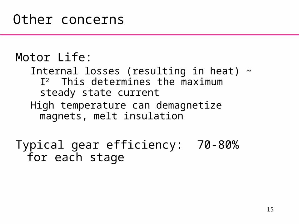
Other concerns
Motor Life: Internal losses (resulting in heat) ~ I2 This
determines the maximum steady state currentHigh temperature can demagnetize magnets, melt
insulation
Typical gear efficiency: 70-80% for each stage

16
Noise suppression capacitors

17
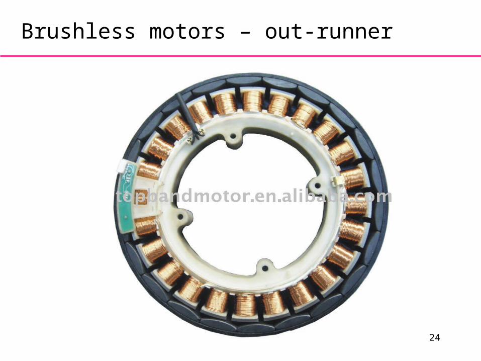
Brushless motors
Stationary coils that are electrically
commutated
Rotating permanent magnets
In-runner – magnetic core inside coils
Out-runner – magnetic cup outside coils
Sense rotor angle using Hall effect sensors or EMF in non-powered coils
Typically three coils wired as Wye or Delta
Bidirectional coil drivers

18
Brushless motors – stator coils, rotor PM

19
Brushless motors - commutation

20
Brushless motors - commutation

21
Brushless motor – in-runner

2222
Brushless motor – out-runner
Magnetic sensor
Magnet
StationaryCoils
Circuitry to switch coil
polarity

23
Brushless motors – out-runner
24
Brushless motors – out-runner

25
Brushless motors – pancake

26
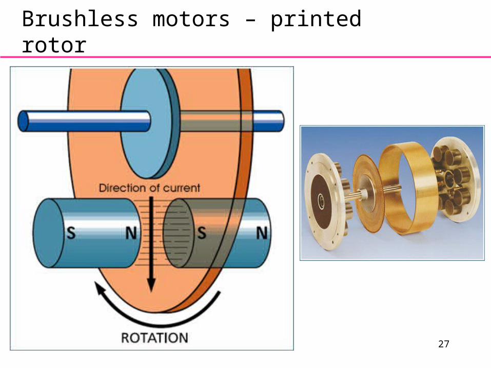
Brushless motors – printed rotor
27
Brushless motors – printed rotor

28
Batteries – types
• Alkaline (C, AA, AAA, 9V)– 1.5V per cell, cheap, generally not rechargeable
• Lead acid (automotive)– 12V, sulphuric acid, never below 10.5V
• Sealed lead acid (SLA) - gel cell, absorbed glass mat (AGM)– 6V or 12V, any orientation, never below 10.5V for 12V
• NiCd (nickel-cadmium)– 1.2V per cell, may discharge completely
• NiMH (nickel-metal-hydride)– 1.2V per cell, NEVER discharge completely, self-discharge
• LiPo (lithium-polymer)– dangerous charge/discharge, limited cycles ~300
• LiFePO4 (lithium-iron-phosphate)– safer, more cycles ~1000

29
Batteries – energy density

30
Batteries – energy density

31
Batteries – rating
• Amp-hours (Ah)– Constant discharge current multiplied by discharge
time before reaching minimum recommended voltage
• C20 rating is Ah available for 20 hours– Example: 12V gel-cell battery with 18 Ah rating can
provide 0.9 A current continuously for 20 hours before reaching 10.5V minimum threshold

32
Batteries – discharge curves
• Lead acid– More linear voltage versus time discharge curve– Higher discharge rate reduces capacity (Peukert’s
Law)– Example: 12V gel-cell battery with 7 Ah C20 rating
• 0.35 A discharge, 20 hours = 7 Ah• 0.65 A discharge, 10 hours = 6.5 Ah• 1.2 A discharge, 5 hours = 6.0 Ah• 4.2 A discharge, 1 hours = 4.2 Ah
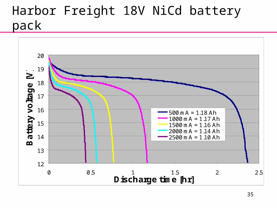
• NiCd– Flatter voltage versus time discharge curve– More difficult to monitor remaining capacity– Discharge rate does not reduce capacity as much
as lead acid

33
12V 18Ah sealed lead acid (SLA)
11
12
13
0 5 10 15 20
Ba
tte
ry V
olt
ag
e [V
]
Discharge Time [hr]
900 mA = 18.9 Ah
2000 mA = 16.9 Ah
3000 mA = 16.1 Ah
4000 mA = 15.6 Ah
5000 mA = 14.9 Ah

34
12V 18Ah sealed lead acid (SLA)
14
16
18
20
0 1000 2000 3000 4000 5000
Constant Current [mA]
Act
ual
Rat
ing
[A
h]
35
Harbor Freight 18V NiCd battery pack
12
13
14
15
16
17
18
19
20
0 0.5 1 1.5 2 2.5Discharge time [hr]
Ba
tte
ry v
olt
ag
e [
V]
500 mA = 1.18 Ah1000 mA = 1.17 Ah1500 mA = 1.16 Ah2000 mA = 1.14 Ah2500 mA = 1.10 Ah

36
Ryobi 18V NiCd Battery Pack

37
Alkaline discharge curves
38
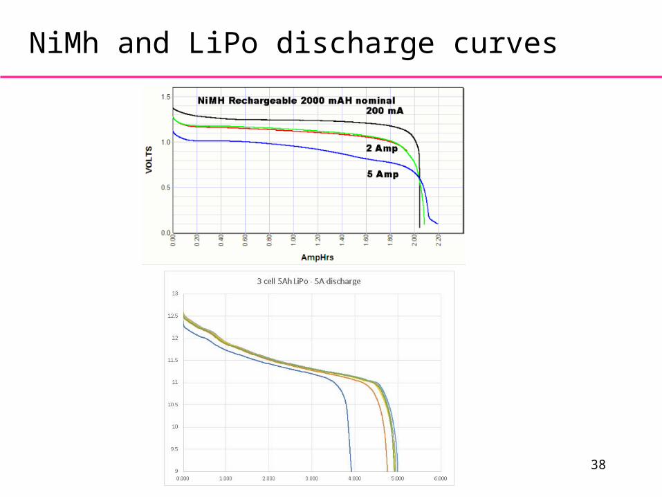
NiMh and LiPo discharge curves


![[The, Commutator] Vol.1 Issue1](https://static.fdocuments.net/doc/165x107/568c534b1a28ab4916ba2bff/the-commutator-vol1-issue1.jpg)
![Alternating Current Commutator Motors .. (1905])](https://static.fdocuments.net/doc/165x107/577cc4bd1a28aba7119a43ff/alternating-current-commutator-motors-1905.jpg)


