0IIII AD-A261 755 I I · PDF file0iiii ad-a261 755 i "" i ii1111. ..... inch-pound...
113
/ AD-A261 755 0IIII I "" I Ii1111. .......... INCH-POUND MIL-HDBK-844(AS) 20 October 1992 MILITARY STANDARDIZATION HANDBOOK AIRCRAFT REFUELING "HANDBOOK COM MIN 93-04682 E - :SMARO ET ASMC NA FSC-9130 Q DISTRIBUTION STATEMENT A. Approved for public release; distribution is unlimited. _ _ _ _ _ _ _ _ _ _ I I ... I-2.IrkII
-
Upload
truongcong -
Category
Documents
-
view
228 -
download
0
Transcript of 0IIII AD-A261 755 I I · PDF file0iiii ad-a261 755 i "" i ii1111. ..... inch-pound...

/
AD-A261 7550IIII I "" I Ii1111. ..........INCH-POUND
MIL-HDBK-844(AS)20 October 1992
MILITARY STANDARDIZATION HANDBOOK
AIRCRAFT REFUELING"HANDBOOK
COM MIN
93-04682 E -:SMARO ET
ASMC NA FSC-9130Q DISTRIBUTION STATEMENT A. Approved for public release; distribution is unlimited.
_ _ _ _ _ _ _ _ _ _ I I ... I-2.IrkII

MIL-HDBK-844(AS)
(
(This page intentionally left blank). 0

MIL-HDBK-844(AS)
Q AIRCRAFT REFUELING HANDBOOK
TABLE OF CONTENTS
CHAPTER 1 INTRODUCTION ............................................. 1-11. 1 PU R PO SE .. ................................ .................... 1-11.2 SC O PE . . . . . . . . . . . . . . . . . . . . . . . . . . . . . . . . . . . . . . . . . . . . . . . . . . . . . . . 1-11.3 C O PIES .. . . .. .. .. . . .. .. ..... .. .. .. ... .. . . . .. . . .. . .. . . .. . .. . . . . 1-11.4 C H A N G ES .. ................................. ........ .......... 1-1
CHAPTER 2 ORGANIZATION AND TRAINING .................................. 2-12.1 ORGANIZATION ................................................ 2-1
2.1.1. G eneral .. . . . . . . .. . . . . . . . . . . . . . . . . . . . . . . . . . . . . . . . . . . . . . . . 2-12.1.2 Responsibilities and Duties . .................................... 2-1
2.1.2.1 Fue! Management Officer (FMO) ............................ 2-12.1.3.2 Assistant Fuel Management Officer (AFMO) ..................... 2-12.1.3.3 Fuel D elivery . ............ ... ........... .. .......... 2-12.1.3.4 Storage and Transfer. ................................. 2-12.1.3.5 Quality Surveillance (QS) ............................... 2-22.1.3.6 Inventory ................................ .... ...... 2-22.1.3.7 T raining . ... .. ... .. .. .. .. .. . .. . .. .. . . . . .. . .. . .. . . . 2-2
2.2 T RA IN IN G .. .................................... ............... 2-2
CHAPTER 3 CHARACTERISTICS OF AVIATION FUELS . ........................... 3-13.1 INT RO D U CT IO N . ............................................... 3-13.2 TURBINE ENGINE FUELS .. ........................................ 3-1
3.2.1 JP-5 (NATO Code F-44) ...................................... 3-23.2.2 JP-4 (NATO Code F-40) .. .................................... 3-23.2.3 JP-8 (NATO Code F-34) ...................................... 3-23.2.4 Turbine Fuel Additives ...... ......................... ....... 3-2
3.2.4.1 Fuel System Icing Inhibitor (FSII) ... ......................... 3-23.2.4.1.1 Icing Protection . .......... ............ ........ 3-33.2.4.1.2 B iostat . . . . . . . . . . . . . . . . . . . . . . . . . . . . . . . . . . . . . 3-33.2.4.1.3 FSII M aterials . ............................... 3-3
3.2.4.2 Lubricity Additive .................................... 3-33.2.4.3 Antioxidant Additives .. ................................ 3-33.2.4.4 Static Dissipator Additive (SDA) (JP-4/JP-8) ..................... 3-4
3.3 AVIATION GASOLINE . ........................................... 3-4
CHAPTER 4 CONTAMINATION OF AIRCRAFT FUELS ............................. 4-14.1 G EN ERA L .. .... ............... .. ........................ ...... 4-14.2 TYPES AND SOURCES OF CONTAMINATION ............................ 4-1
4.2.1 PARTICULATE MATTER . ................................... 4-14.2.2 W AT ER . .............................. ..... ............ 4-24.2.3 CHEMICAL CONTAMINATION ................................ 4-34.2.4 M ICROORGANISMS .. ...................................... 4-3
4.3. COMMON SOURCES OF CONTAM-INATION .............................. 4-44.4 PROCEDURES FOR PREVENTING CONTAMINATION ....................... 4-44.5 DETERIORATION OF AIRCRAFT FUELS ................................ 4-54.6 SAMPLING OF AVIATION FUELS ..................................... 4-5
0 4.6=• -- ,_

MIL-HDBK-844(AS)
CHAPTER 5 FLEET QUALITY SURVEILLANCE TESTS ............................ 5-15 .1 . . . . . . . . . . . . . . . . . . . . . . . . . . . . . . . . . . . . . . . . . . . . . . . . . . . . . . . . . . . . 5-15.2 PARTICULATE CONTAMINATION .................................... 5-1
5.2.1 CFD Test Technique ......................................... 5-15.2.2 CFD Operating Procedure . ..................................... 5-25.2.3 Alternate M ethods . ......................................... 5-2/J
"5.3 WATER CONTAMINATION ......................................... 5-35.3.1 FW D Test Technique . ....................................... 5-35.3.2 FW D Operating Procedure ..................................... 5-35.3.3 Alternate M ethod .. ......................................... 5-3
5.4 FUEL SYSTEM ICING INHIBITOR (FSII) CONTENT ......................... 5-45.4.1 B/2 Test Technique .......................................... 5-45.4.2 B/2 Operating Procedures ...................................... 5-4
5.5 CONDUCTIVITY . ............................................... 5-4
CHAPTER 6 SAFETY IN FUEL HANDLING OPERATIONS ............................ 6-I6.1 INTRODUCTION . ............................................... 6-16.2 ABNORMAL FUEL OPFRATIONS ..................................... 6-I6.3 FIRE AND EXPLOSION ............................................ 6-1
6.3.1 FLAMMABLE FUEL-AIR MIXTURES ............................ 6-16.3.1.1 LOW VAPOR PRESSURE PRODUCTS ...................... 6-I6.3.1.2 INTERMEDIATE VAPOR PRESSURE PRODUCTS .............. 6-26.3.1.3 HIGH VAPOR PRESSURE PRODUCTS ....................... 6-2
6.3.2 FLAME SPREAD RATES ..................................... 6-26.4 SOURCES OF IGNITION ........................................... 6-4
6.4.1 STATIC ELECTRICITY ...................................... 6-46.4.1.1 INTERNAL STATIC.. ................................. 6-5
6.4. 1. I.I Charge Generation .... ........................... 6-56.4.1.1.2 Charge Accumulation ............................. 6-56.4.1.1.3 STATIC DISCHARGE OR IGNITION ................. 6-56.4.1.1.4 CONTROl. MEASURES.. ............ ........... 6-6
6.4.1.2 EXTERNAL STATIC ................................. 6-66.4.1.2.1 Charge Generation .............................. 6-66.4.1.2.2 Charge Accumukation and Dissipation ................... 6-66.4.1.2.3 Control Measures for External Static ................... 6-7
6.4.2 OPERATING ENGINES ...................................... 6-76.4.3 ARCING OF ELECTRICAL CIRCUITS .............................. 6-76.4.4 OPEN FLAM ES ........................................... 6-76.4.5 ELECTROMAGNETIC ENERGY ................................ 6-76.4.6 HOT SURFACES OR ENVIRON-MENT ............................ 6-7
6.5 EXTINGUISHM ENT . ............................................. 6-76.5.1 Fire Chem istry . ...... .................... ................. 6 86.5.2 Classitication of Fires.. ....................................... 6-8
6.5.2.1 Class A Fires ....................................... 6-86.5.2.2 Class B Fires .. ...................................... 6-86.5.2.3 Class C Fires . ...................................... 6-86.5.2.4 Class D Fires .. ..................................... 6-8
6.5.3 Fire Extinguisher Types, Agents, and Methods of Application ............... 6-86.5.3.1 H alon 1211 .. ........... ............... .... .. ..... 6-8
6.5.3.1.1 D efinit.on . ... ............................... 6-86.5.3.1.2 Application . ................................. 6-9
ii

MIL-HDBK-844(AS)
0 6.5.3.2 Carbon Dioxide (CO)) ................................. 6-96.5.3.2.1 Definition. ................................... 6-96.5.3.2,2 Application ................................... 6-9
6.5.3.3 Purple-K-Powder (PKP) .................................... 6-106.5.3.3.1 Definition.... .................................. 6-106.5.3.3.2 Application .................................. 6-10
6.6 HEALTH HAZARDSA................................................. 6-106.6.1 TOXIC VAPOR EFFECT .................................... 6-106.6.2 LEAD POISONING ........................................ 6-136.6.3 INJURY TO SKIN AND EYES ................................. 6-136.6.4 SWALLOWING AVIATION FUELS ............................. 6-136.6.5 FUEL TANK AND FILTERISEPAR-ATOR WATER BOTTOMS .......... 6-136.6.6 SPECIFIC PROCEDURES FOR AVOIDING THE HEALTH HAZARDS OF
AIRCRAFT FUELS ....................................... 6-13
APPENDIX A VISUAL CONTAMINATION TABLE ................................. A-I
APPENDIX B PETROLEUM TESTING LABORATORIES ............................. B-I
APPENDIX C AIRCRAFT INFORMATION SUMMARIES ............................... C-IA -6 . . . . . . . . . . . . . . . . . . . . . . . . . . . . . . . . . . . . . . . . . . . . . . . . . . . . . . . . . . . . C -2A V -8B. . . .. .. . . .. . ... . ..... . ... . .. .. .. .. ... . . . . .. .. . . .. .. .. .. . .. . C -7E -2/C -2 . . . . . . . . . . . . . . . . . . . . . . . . . . . . . . . . . . . . . . . . . . . . . . . . . . . . . . . . C -12F -14 . . . . . . . . . . . . . . . . . . . . . . . . . . . . . . . . . . . . . . . . . . . . . . . . . . . . . . . . . . C -16F-18 . . . . . . . . . . . . . . . . . . . . . . . . . . . . . . . . . . ... . . . . . . . . . . . . . . . . . . . . . . C -20S -3 . . . . . . . . . . . . . . . . . . . . . . . . . . . . . . . . . . . . . . . . . . . . . . . . . . . . . . . . . . . C -25P -3 . . . . . . . . . . . . . . . . . . . . . . . . . . . . . . . . . . . . . . . . . . . . . . . . . . . . . . . . . . . C -29H -I . . . . . . . . . . . . . . . . . . . . . . . . . . . . . . . . . . . . . . . . . . . . . . . . . . . . . . . . . . . C -33H -2 . . . . . . . . . . . . . . . . . . . . . . . . . . . . . . . . . . . . . . . . . . . . . . . . . . . . . . . . . . . C -37H -3 . . . . . . . . . . . . . . . . . . . . . . . . . . . . . . . . . . . . . . . . . . . . . . . . . . . . . . . . . . . C -4 1H -46 . . . . . . . . . . . . . . . . . . . . . . . . . . . . . . . . . . . . . . . . . . . . . . . . . . . . . . . . . . C -45H -53 . . . . . . . . . . . . . . . . . . . . . . . . . . . . . . . . . . . . . . . . . . . . . . . . . . . . . . . . . . C -49SH -60 . . . . . . . . . . . . . . . . . . . . . . . . . . . . . . . . . . . . . . . . . . . . . . . . . . . . . . . . . C -54
APPENDIX D GLOSSARY ................................................. D-1
Aesession For
ITIS GRA&IDTIC TAB QUna•oxnced 0Just fflc/tl/o
By
Av& il and/or"

MIL-HDBK-844(AS)
(This page intentionally left blank).
iv

MIL-HDBK-844(AS)
0 CHAPTER 1
INTRODUCTION
1.1 PURPOSE. This handbook provides basic Standardization Documents Order Deskinformation on the properties and characteristics of Bldg 4Daviation fuels along with general information on the 700 Robbins Avenuestandards, equipment, and operating principals related Philadelphia, PA 19111-5094to the handling of these fuels at Navy and MarineCorps activities, it is designed to supplement the 1.4 CHANGES. The information containedNATOPS AIRCRAFT REFUELING MANUAL, herein has been derived from a number of diverseNATOPS 00-80T-109, by providing background sources including: the fueling experience of theinformation and guidance on the requirements and Navy, Marine Corps, and commercial companies; theprocedures contained in the NATOPS Manual. recommended practices of the American Petroleum
Institute and the American Society for Testing and1.2 SCOPE. The contents of this handbook are Materials; and the published findings of research
limited to technical and operational information of a activities.general nature. Specific operating procedures andequipment requirements are contained in the Operating activities are encouraged to submitNATOPS AIRCRAFT REFUELING MANUAL, corrections, recommended changes, or innovationsNATOPS 00-80T-109. Accounting and stock control for this handbook by letter to:procedures are not included in this handbook or theNATOPS Manual. Commander
Naval Air Systems Command1.3 COPIES. Copies of this Military AIR-5363C
Handbook are from: Washington, D.C. 20361-5360
MIL-HDBK-844(AS)
0
(This page intentionally left blank).
1-2

MIL-HDBK-844(AS)
CHAPTER 2
ORGANIZATION AND TRAINING
2.1 ORGANIZATION instruction in accordance with the NATOPS AircraftRefueling Manual and other applicable documents.
2.1.1. General. The allowances for a Fuel e. Prepares an oil spill prevention and counter-Division should include personnel in adequate measure plan.quantities and with sufficient grade structure, f. Prepares environmental impact statement fortraining, and seniority to ensure responsible operation the U.S. Coast Guard on any procedural change andof facilities and equipment in response to any modification to plant facilities.operational demand. g. Plans and initiates military construction,
repair, and improvement fuel projects.The organization should be flexible enough to h. Performs liaison with fuel service customers,
efficiently handle increased workload on short notice. activity departments, other governmental agencies,This can best be accomplished by cross training and community official and commercial concerns.cross manning. Leave schedules and school i. Represents fuel interests on boards andattendance can be adjusted to accommodate workload committees.peaks. Scheduled leave can be deferred if unexpectedpeaks are encountered. Lengthening working shifts 2.1.3.2 Assistant.Fuel Management Officerand non-standard duty section, including stand-by (AFMO). The AFMO assists the FMO in theduty section assignments, should be last resort supervision of the integrated fuel operations andmeasures. performs the following special duties:
D Chapter 8 of the NATOPS Aircraft Refueling a. Directs the quality assurance program for fuelManual, NAVAIR 00-80T-109, outlines a products.recommended standard organizational structure for b. Manages the petroleum laboratory.Navy and Marine Corps fuel operations division. c. Directs entire fuel training program.Shipboard organizational structures are established by d. Supervises inspections.applicable regulations and/or standard operating e. Maintains inventory control.procedures instructions.
2.1.3.3 Fuel Delivery. The employee placed in2.1.2 Responsihilities and Duties. The NATOPS charge of the fuel delivery section or branch is
Aircraft Refueling Manual, NAVAIR 00-80T-109, normally delegated the following specific duties:delineates fuels responsibilities at shore activities.For Shipboard operations, consult Shipboard a. Delivery of aviation POL products alongsideOperation Regulation Manual 3120.32. aircraft.
b. Operation of hydrants to fuel aircraft withThe Ibllowing paragraphs list the normal duties engines idling (hot refueling).
assigned to various personnel within a typical shore c. Operation of aircraft defuelers.activity fuels organization. d. Dispatching of personnel and/or equipment
and maintenance of dispatch log.2.1.2.1 Fuel Managernent Officer (FMO). e. Delivery of ground products on automatic fill
Directs and supervises the completely integrated fuel basis or as requested.operations. An FMO typically: f. Pickup of waste oil.
g. Operational maintenance of facilities anda. Estimates quantities of fuel products to be equipment.
consumed and fuel servi4e requirements.b. Develops proposed fuel budget. 2.1.3.4 Storage and Transfer. The branch orc. Pertbrms contract administration services. section head in charge of fuel storage and deliveryd. Prepares and revises the activity fuel usually is assigned the following duties:
2-1

MIL-HDBK-844(AS)
a. Receipt of POL products by pipeline tanker, 2.2 TRAINING. It is essential to the safety ofbarge, tank car or tank truck. fuel handling operations that the personnel involved
h. Storage of products. be properly trained. Historical records disclose thatc. Operation of the distribution systems and the instinctive reactions of experienced fuel operators
transferring of products. during emergency situations have mioimizedd. Operation of vehicle service stations, personnel injuries, fuel losses, and the destruction ofe. Grass cutting in hazardous areas, government prcperty including aircraft. Conversely,f. Receipt and storage of packaged POL the records show that the reactions of relatively
products. untrained personnel, under similar situations, cannotg. Operational maintenance of facilities and be relied upon. The importance of proper training
equipment. can not be over-emphasized.
2.1.3.5 Quality Surveillance (QS). The QSbranch normally performs the following:
a. Sampling POL products at point of receipt, instorage, when trastsferred in aircraft refuelers andaircraft tanks.
b. Surveillance of fuel handling operations.c. Surveillance of POL filtration, water removal
and monitoring equipment including the maintenanceof pressure differential graphs.
d. Operation of the POL laboratory.e. Inspection and surveillance or tacilities and
equipments including contract-owned equipment.
2.1.3.6 Inventory. The Inventory branch usuallyperforms the following functions:
a. Estimates ot' POL requirements.b. Scheduling of product deliveries.c. Preparation of fuel requisitions for
replenishments.d. Maintenance of daily inventory records.e. Processing of receipt and issue documents.h. Monitoring of contract refueling fuol
deliveries.
2.1.3.7 Training. The branch assigned thetraining function normally perfbrms the followingduties:
a. Preparation of training guide.b. Conducting classroom and on-the-job
training.c. Certifying qualifications and issuing
certificates.d. Maintenance of training and qualification
records,e. Reviewing and supplementing contractors'
training program. 0
2-2

MIL-HDBK-844(AS)
D CHAPTER 3
CHARACTERISTICS OFAVIATION FUELS
3.1 INTRODUCTION. There are basically technical authority for the piece of equipment intwo different types of aircraft fuels in use at Navy question.and Marine Corps air activities - turbine engine fuelsand aviation gasolines (AVGAS). A knowledge of Aviation gasolines are used for piston-typesome of the basic properties and characteristics of (reciprocating) engines which are similar tothese fuels is necessary in understanding the automotive engines in terms of their basic operatingimportance of delivering the proper fuel to the principle. Turbine engine fuels, on the other hand,aircraft. Such knowledge is also valuabie in are intended for use in an entirely different type ofunderstanding the need for safety and caution in engine. In place of the pistons found in reciprocatinghandling aviation fuels. engines, turbine engines have an air compressor, a
combustor, and a turbine which they use to turn fuelTurbine engine fuels and aviation gasolines are into usable propulsion energy. Since these are
petro!eum products manufactured from crude oil by completely different types of engines, they requirerefineries. Both are classified as flammable liquids different types of fuels for proper operation. Theand will burn when ignited. Under the right following paragraphs provide some specificconditions, they will e!xplode with forces similar to information on each type of fue!.those of dynamite. Death can result if the vapors of
D either type tuel are inhaled in sufficient quantities and 3.2 TURBINE ENGINE FUELS. Whileserious skin irritation can result from contact with the aircraft piston engines are sensitive to the fuel usedfuels in the liquid form. In the liquid form. aircraft and will only operate safcly and satisfactorily on onefuels are lighter than water and in the vapor form grade of aviation gasoline, most aircraft turbinethe)y are heavier than air. Consequently, any water engines can use a varicey of grades of aviation turbinepresent in the fuels will usually settle to the bottom of fuels. The diff;rcnce between the grades of turbinethe container. On the other hand, vapors of these fuels is their volatility. TFable 3-1 lists the morefuels, when released in 'he air, tend to remain close common grades of military and commercial aviationto the ground, thus increasing the d:nger to personnel turbine fuels and gives a rough comparison of theirand proper~y. For safety and he:lth considerations, Volatilities through their flash points (a measure otb,)th aviauion gasolines and turbine engine fuels must the temperature at which the fuel can he ignited whenhe handled with equal caution. Additional sitting in a pool) and freeze points (the temperatureinformation of the properties and characteristics of at which the fuel forms solid crystals). Detailedaviation fuels and their effects on the safe handling of information on the properties and requirements ofthese materials is contained in Chapter 6 of this each grade of fuel is contained in the applicablehindhook: specification.
All aviation fuels are extremely good solvents. Although kerosene type turbine fuels, JP-5 andFor example, AVGAS will dissolve common JP-8, are much less volatile than JP-4 and AVGAS,lubricants (such as oils and greases used in pumps, under the right conditions, such as severe agitition,valve, packing. and tither equipment) and can cause mists can form which are as flammable and explosiveserious deterioration of rany rubber materials. It is as AVGAS. All aviation fuels must be handledtherefore extremely important that only materials carefully.specially designed, tested, and approved fur use withaviation fuels he allowed to come into contact withD• them. Never use substitute greases, lubricants,packing, etc. on or with fuel handling equipmentwithout first obtaining agreement from the cognizant
3-1

Mit-HO BK-844 (AS)
I dT rcfiain Fe Tylv NATO Frocze Flash~ Point DensityF r d S t c f c Ii n F I C O D E P to i t _ _ _ _ _ _ ( * A P I G r a v i ty )
JP-5 NI1L-T-5624 Kerosene F-44 -51*F 1401 F 360-48.07(High Flash) -46'C 60*C
Mtilitary J P-4 NtIL-T-56:4 NV'ide-C~i F..AO -72*F below -4*F 45.C-57.0-s8.c -200 C
IP-8 MIL-T-83 133 Kerosene F-34 -53'F 100'F 37.0-51.0-7C 38.c
let A ASTNI D 1655 Keromrne none -40*F I00'F 37.0-51 0
-40*C 38*C
Commerial~j Jet A- I ASTNI D 1655 Kerosene F-35 *53*F I 00'F 37.0-51.0
L____ 47*C 38*C
Jet B ASTI D 1655 Wide Colt on -72*F below -4*F 45-0-57 0
L ~ t- I_____ I___________-______ - -58 -*C
Table 3-I1. Grades of Turbine Engine Fuels.
3.2.1 JP-5 (NATO Code F-44). JP-5 is a order to take advanta_-e of its similarity tokerosene fuel with an especially high flash point commercial aviation turbine fuel and improved safetyfacilitating safety in shiphoard handling. It is the only (lower volatility).fuel that can he used for turbine engine aircraftaboard shipis and is used widely at UISN and LSMC 3.2.4 Turbine Fuel Additive.. Although JP-5air stations. Because it has the highest density of all and JP-8 are quite similar ito commercial turbine fuels 0the aviation fuels. J P-5 h as the greatest affinity for Jet A and Jet A-I and JP-4 is :asically the same fueldirt, rust, and waiter conc:Iminants. as Jet 13. there are some very important diffcrenccs.
In addition ito smazll but si-nificant diffterenc:es in3.2.2 JlP-4 (NATO Code F-40). JP-4 is the volatility, all three military fuels contain thie
primar\ fuel used at Air Force and Armyv bases in following additives which commercial jet fuelsCONUS. 111-4 is a -Aide boiling range petroleum normally do nut[:product including both gasoline and kerosene boilinLgrainge :ompilnents. RP-4 exhibits better iowl a. Fuel System [,ing, Inhibitior ([511)temperature starting than J P-5. JP-4 fuel is b. ILubricity AdditiVe (corros 'on inhiibitor)inte~rmediate hetween A VGA.S and JP-5 with respect c. Antit)Kidants (storage stability~ additives)Io Its tendlencies to acquire and hold dirt. ru~t, and d. Static Dissipator Addilive (JP"-4 and J P-8wkatvrcnamnns It is an alternate fuel to JI'-5 for fuels only)li.SN and IISNIC Jet aircraft. Both JP-4 and JP-5tuels are procuredl under MilIitary Spec ificat ion J P-4 and JP-8 fuels also contain sataric dissipalter.\fL-T-5024. z~dditive (SDA) ito improve their relaxatiin of staitic:
charges crcat.A by filtrat ion and fuel mo vemnent.3.2.3 .111-8 (NATO Code F-34). JP-8, Since certain approved SIMA additives adveisely
procured uinder Military Specification NHL-T-83133. affect the performance of' filter/separators. SIJA isis a kerosene fuel similar ito commercial jet fuel, not added to JlP-5. J11-5 handling systetns mustASiNI Jet A-I. except JP-8 contains fuel system icing tlier;.fore have static charge relaxation chambers atinhibitor as well as other fuel additives. It is also appropriate points in order to eliminate static charges.;similar to JP-5 with respect to most fuel propertiesexýcept flash point and freeze point. Since its flash 3.2.4.1 Fu~el System Icing Inhibitor (F.SI ).point is not as high as 111-5's it cannot be used foir FSII is added to the fuel for two reasons, it providesshipboaru operations. The Air Force is c:urrently in icing protection and also act., as a biostat.the process of' converting oiperatio~ns to J P-8 fuel in
3-2

MIL-HDBK-844(AS)
3.2.4.1.1 Icing Protctiin. Even whn the considered mutagenic in the neat state but are
tree water content ot the fuel is maintained be!ow the considered safe once blended into the fuel. Most5 ppm level, FSII is essential because, in addition to FSII is injected at the refinery or Defense Fuelfree water, aviation fuel contains a significant amount Supply Depot. Shoreside personnel involved in theof dissolved water. In general, the amount of handling and injection of these additives are adviseddissolved water a fuel will hold in parts per million to follow all instructions, wear gloves and aprons.(ppmt is approximately equal to the temperature of and minimize their exposure as much as possible.the fuel in degrees fahrenheit. For example, a fuel Since FSII materials tend to become concentrated in"which is 70cI: contains approximately 70 ppm the water which collects at the bottoms, of fuel tanksdissolved water. Itf this fuel were cooled to 207F it (aircraft as well as fuel storage) and filter/separators.would then contain 50 ppm free water and 20 ppm personnel handling these waterbottoms are advised todissolved water. When an aircraft is exposed to cold follow similar precautions.temperatures such as high altitudes or very coldS .ieather conditions at sea level, the fuel contained in 3.2.4.1.3.1 EGME. Ethylene Glycolits tanks will drop in temperature allowing the water Monomethyl Ether. defined by MIL-I-27686. is the,.khich is dissol,,ed in the fuel to condense out into approved FSII material kfor use in hoth JP-4 and JP-8tiny droplets of free water. If the temperature of the fuels. It is also the original FSII material used infuel drops low enough (below 32°F) these droplets JP-5. Older stocks of JP-5 mav contain EGME sincewill form ice crystals which will collect on screens or complete conversion of all FSII injection facilities tofilters in the fuel systern quickly blocking them. In DiEGME was only recently accomplished.addlition, the ice crystals can cause fuel system valvestoi ,tick or nal function preventing the aircraft pilot 3.2.4.1.3.2 Di EG\I E. Diethvlene -lvcolfrom using or distributing hiis fuel load. .lonomethyl Ether. procured to MIL-1-85470. is
currently the only approved FS1I additive for use inThe result of using fuel without sufficient FSII JP-5 hecause of its high flash point. Since DiIGNIE
can be the loss of an aircraft. Certain aircraft are is also considered significantly less mutaigenic thanmore susceptible to these problems than others EGME, JP-4 and JP-8 are currently heing convertedbecause of differences in their fuel system desigtn as to the use of this FSl additive.
well as possihle flight profiles. These aircraft are theS-3A. US-3A. and S11-60. For this reason they 3.2.4.2 Luhricity Additive. A combinationrequire a minimum FS11 level of 0.03 percent by lubricity improver and corrosion inhibitor additive,volume in their tuel. All other USN and USNIC procured under MIL-l-25017, is injected in allai:craft do not require FSII and may use JP-5 or Military turbine fuels at the refinery in order totother approved fuel even if it does not contain any improve the lubricating characteristics of the fuel. AFSlI. series of several contiguous (one immediately
following another) flights with fuel which does not3.2.4.1.2 Biostal. FSII prevents the growth of contain one of these additives may cause abnormal
Sfunguses and other microorganisrns which can wear or malfunctions or aircraft and/or engine fueldevelop at the interface between the fuel and any system components. A few Ilights (one or two) willwater v, hich cill; ects at the hottomr of the tank not contribute to such pro•lems since the additives(aircraft as well as fuel stor:ge). Since these tend to leave a protective coating on the components.mienirbhiohogical gri wths can forin rapidly, clogllilters, and degrade the fuel, every elffort should be 3.2.4.3 Antiox•idant Additivts. Thesen:ide to in:iintain FSII levels as high :is possible in materials, which are injected into the fuel :it theorder t i maximin/c its bii static effect. The best way refinery, are particularly important !*or fuels whichif "naintainino these levels is to minimize contact of have been processed at the refinery with hydrogen.the fuel with water okhich tends to leach out the FSII They insure that the fuel will be stable when placedfromt the fuel. F-44 tanks inust therefore be stripped in long term storage (a tew months to several years).of water frequently - daily if any significant amnount Commercial fuels doi not need these additives sinceof water accumulates within a 24 hour period, they are usually consumed within a few weeks to a
couple of r.onths. The first fuel property to drop3.2.4.1.3 FSIi Materials. There are currently below specification minimums in an unstable fuel is
two approved FSPI materials. Btoth FSII materials are usually its thermal stability. Other properties such as
3-3
A,--t--

MIL-HDBK-844(AS)
total acid number, copper strip corrosion, and be necessary in order to prevent aircraft damage.cxistent gums can al-o fall below acceptable More information and assistance on this subject mayminimums. be obtained from the USAF Technical Support Team
located at Kelly Air. Force Base, TX (DSN3.2.4.4 Static Dissipator Additive (SDA) 9454617).
(JP-4/JP-8). JP-4 and JP-8 fuels are injected with aspecial additive which increases the fuel's In a couple of special situations where very largeconductivity and helps relax static electric charges numbers of USAF aircraft are frequently refueled itwhich are produced during fuel handling operations may be necessary to have the JP-5 supplied to a naval(filtration, pipeline movement. etc.). Static Dissipator air station injected with SDA. The aboveAdditive (SDA), as this additive is now called, was deterioration use limits are then applicable to JP-5.originally added to these fuels to prevent small staticinitiated explosions which were occurring during 3.3 AVIATION GASOLINE. Very littlerefueling of polyester foam filled USAF aircraft aviation gasoline (AVGAS) is currently being used bytanks. The USN and USMC have never experienced the U.S. Military services. For this reason thesimilar problems with foam filled tanks probably due Military AVGAS Specification, MIL-G-5572, wasto aircraft tank and refueling equipment design cancelled in 198E and Military needs are beingdifferences. In addition, limited laboratory testing of satisfied via the commercial specification, ASTM DSDA in JP-5 indicates one of the currently approved 910.SDA additive materials has an adverse effect on theperformance of filter/separators in their removal of Aviation gasolines are graded according to theirparticulates and tree water from the fuel. SDA has performance in a similar manner to the "octane"therefore not been added to JP-5. ratings used for automotive gasolines. "Performance
Numbers." as they are called ftýr aviation gasoline.When USAF or foreign government aircraft are are also based on the performance of the fuel in
refueled with JP-4 or JP-8, the fuel must exhibit preventing engine knock, an extremely seriousconductivity above 100 p.S/m as measured by a problem in aircraft engines due to the continuousporthble condutivitv meter. NSN 6030-01-115-2398. high power demands placed upon them. The gradesAn upper use limit ot 700 pS/m has been established otfAVGAS were tormerly designated by two numbersto protect the accuracy of cer,ain sensitive aircraft i.e. 100/130. The first number indicated thefuel quantity gauging systems. Since SDA is performance rating with a lean fuel-air mixture whiledepleted in the supply distribution system, USAF the second number indicated the knock rating with apolicy has been to add the additive is close as rich fuel-air mixture. The new ASTM designationsoossible to the using activity or base. SDA is tfr these fuels now only refer to the lean knocktherefore most often being added at Defense Fuel rating. As listed in. Table 3-2, the three grades otSuppOrt Points (DFSP's). AVGAS are dyed various colors in order that they
can be easily distinguished.It is not necessary for USN or USMC activities
to frequently test the conductivity levels of their Grade 100 (high lead) and IOOLL (low lead)stocks of JP-4 or JP-8 fuel when they are only. have exactly the same performance characteristicsandref:eling USN or USMC aircraft. However. can he used interchangeably. The refining industryo: isional testing of the conductivity of these fuels is in the U.S. has been changing over to the lower leadrc-oninmended in order to ensure that SDA is being version in order to meet Environmental Protectioniulected at the proper level. especiaily since Agency requirements. Grade 100 and Grade I0OLLexce .:vely high levels can affect the accuracy of may also be commingled in storage tanks at airc,.vrtain aircraft gauging systems. If on such checks stations. Please note that if these two fuels are mixedtte fuel is tbund to be out of the specification an unusual color may result. Grade 80 is a very lowctonductivity range, the injecting facility (DFSP or lead fuel with a lower perfiormance rating. The veryietlnerv) should be informed immediately so that the high performance fuel. 115/145, has almostinjectio. rate can be adjusted accordingly. In some campletely disappeared and aircraft which used to;ns:mnces where the refueling of USAF aircraft is demand this fuel have been modified, to acceptinvolved, manual addition of SDA at base level may 100LL.
3-4

MIL-HDBK-844(AS)
Since Avgas is the lightest (lowest density) naval All AVGAS contains some tetra-ethyl lead foraviation fuel, it has the least tendency to acquire and the improvement of its anti-knock performance. Thehold in solution dirt, rust, and water contaminants presence of this fuel additive makes it verymaking it the easiest aviation fuel to keep clean, deleterious to turbine engines so it is extremely
important that turbine fuels not be contaminated witheven small amounts of AVGAS.
ASTM D 910 MIL-G-5572 Color NATO Symbol
Grade 80 80/87 Red
Grade 100 100/130 Green
Grade MOLL 100/130 Low Lead Blue F-18
115/145 Purple
Table 3-2. Grades of Aviation Gasoline
0
3-5
MIL-HDBK-844(AS)
I
(This page intentionally left blank.)
3-6
MIL-HDBK-844(AS)
0 CHAPTER 4
CONTAMINATION OF AIRCRAFT FUELS
4.1 GENERAL. Basic information and 4.2 TYPES AND SOURCES OFminimum requirements pertaining to the quality CONTAMINATION. Aircraft fuel can becontrol of aviation fuels at Navy and Marine Corps contaminated with particulate matter, free water,air activities are contained in Chapters 3 and 9 of the foreign chemicals, microorganisms, or anyNATOPS Aircraft Refueling Manual, NAVAIR 00- combination of the four. In addition to the following80T-109. This chapter provides a brief review of paragraphs which discuss these various types ofthese requirements with amplifying information, contamination. Appendix A is a guide to help in the
detection and understanding of the consequences ofThe major objective of fuel handling personnel the various types of contamination. In practice any
is to deliver clean, water-free, and correct fuel to significant (deleterious) amount of coarse materialaircraft. The fuel systems of modern aircraft are contaminant can usually be detected visually.complex and will not function properly if fuel iscontaminated with dirt, water, or other foreign 4.2.1 PARTICULATE MATTER. Particulatematter. Foreign matter in fuel can plug or restrict matter appears as dust, powder, grains, flakes, fibers.fuel pumping and metering equipment and accelerate or stain. Particulate matter, or solid contamination.the clogging of fuel filters. Fuel contaminated with can be separated into two categories: (a) coarsewater is harmful because ice may he firmed at high matter and (h) fine matter.altitudes also clogging aircraft components. Thepresence of water also permits the growth of (a) Coarse matter is matter tha; can be seen andmicroorganisms in aircraft fuel tanks which hinder that easily settles out of fuel or can he removed bythe operation of components and cause corrosion in adequate filtration. Ordinarily, Particles 10 micronsfuel system,;. in size and larger are regarded as coarse matter. (a
micron is Ill ,0,00.th of a meter or approxinmatelvAircraft engine failure or poor performance may 1/25.000th of an inch). Figure 4-I illustrate just how
also be caused by incorrect fuel or by contamination small these particles can be. Coarse particles clogof the proper fuel with other petroleum products., orifices and wedge in sliding valve clearances andi-Or example, a small amount of turbine engine fuel shoulders, causing malfunctions totf fuel controls andin aviation gasoline can significantly reduce its anti- metering equipment. They are also effective inknock quality. Similarly diesel fuel. lubricating oils clogging nozzle screens and other fine screensand hydraulic tflids are harmful to the quality of both throughout the aircraft fuel system.Nypes of aviation fuels. Any contamination of
aviation fuels is to be avoided. (b) Fine matter may be defined as particlessmaller than 10 microns. TO a limited degree. fine
As a general rule, for aviation fuel to he matter can be removed by settling, filtration, and thea,:ceptable to aircraft it must he clear, bright, and use of centrifugal purifiers. Particles in this rangecontain no free water. The terms "clear" and accumulate throughout fuel controls, appearing as a"bright" are independent tof' natural color of the fuel. dark shellac-like surface on sliding valves, and may
The various grades of aviation gasoline have dycs also be settled out in rotating chambers as sludge-likeadded. Turbine fuels are not dyed and may he any matter, causing sluggish operation of fuel meteringcolor from water-white to straw yellow. "Clear" equipment. Fine particles are not visible to themeans the absence of any cloud, emulsion, readily naked eye as distinct or separate particles: they will,visible particulate matter, or entrained water, however, scatter light and may appear as po int"Bright" refers to the shiny appearance of clean, dry flashes of light or a slight h;ue in fuel. Occasionallyfuels. A cloud, haze, specks of particulate matter, or a fuel contaminatcd with gross amounts of fineentrained water indicates that the fuel is unsuitable particulate matter may be encountcred which does notand points to a breakdown in fuel handling equipment respond to normal filtration and cleanup procedures,
or procedures. For shipboard applications r.otify TYCOM or higher
4.1
i w iiin m u muI I

MIL-HDBK-844(AS)
authority for guidance. It may be necessary to install contamination. Although hose pickling is designed tospecial 2 micron filters in order to bring such a fuel prevent this type of contamination it is not alwayswithin deterioration use limits, successful in doing so. Hoses manufactured to API
1529/NFPA 407 do not have a talc problem and donot need to be "pickled".
4.2.2 WATER. Free water (undissolved water)is a common contaminant of fuels and refuelingpersonnel must be concerned with it in two forms:(1) entrained in the fuel and (2) as a separate phase(liquid water). Entrained water is found in fuels inthe form of very small droplets, fog, or mist and itmay or may not be visible. When large quantities ofentrained water are present, the fuel will have a hazy
A;Rlct.s : L•' or milky appearance. Water usually becomesentrained in the fuel when it is broken up into small
: "V:C •" ', "'1 droplets and thoroughly mixed with the fuel inequipment such as pumps or meters. Given sufficienttime and the proper conditions, entrained water willsettle and separate from aviation gasoline; however.
Figure 4-1. Enlargement of Small Particles since they are fairly dense compared to AVGAS orand Comparison to Human Hair motor gasoline, turbine engine fuels will hold
entrained water in suspension for long periods ofParticulate matter contamination most prevalent time. Once separated and settled from the fuel, water
in aircraft fuels are iron rust and scale, sand. and will collect at the bottoms of tanks, pipes and otherairborne dirt. The principal source of iron rust and fuel system components.scale is the corrosion in pipelines, storage tanks, and Cother fuel containers. Sand and dirt are particularly Fuel will actually dissolve a small amount of
serious in extremely sandy or dusty areas. water. Dissolved water is absorbed into the fuel andis not visible. The amount a fuel will hold in a
Experience has shown that solid contaminants dissolved state is dependent upon the fuel's(rust and dirt) can be held well below a level of I temperature. A rough correlation can be madenilligram per liter (mg/liter) in a properly between a fuel's temperature in degrees Fahrenheitfunctioning fuel distribution system. If sold and the amount of water which can he dissolved in it.contamin.ants in fuel at aircraft dispensing points For example, a fuel at 60(F will hold approximatelyexceed I mg/liter when measured by the 60 parts per million (ppm) dissolved water, while atCiitaninated FucLI Detector. ,r by lahora•ory 30°1F it will only hold 30 ppm. It is important toanalysis (ASTIM Method D-2276). investigative and note that as a fuel cools dohwn, the water which iscorrective action should he takcn to improve fuel dissolved in it at the higher temperature will come
quattity. If solid contanmin:ants exceed 2 iug/liter. out of'solution and become free water.delivery of fuel to aircraft will he stopped andcorrective measures completed prior to restimption of Free water may bh fresh or saline. Free waterfueling operation! . may be in the torm of a cloud, emulsion, entrained
driplets, or in gross amounts in the bottom of' a tankHoise 'ralc can he a source of fuel ciontamination or container. Any inrn of free water can cause icing
with sonie older types of hoses - especially the in the aircraft fuel system cimponents. A Fuelcollapsible varieties. Talc (,soapstone) material, which System Icing Inhibitor (FS II) is added to JP-4. JP-5,is applied to the interior of the hose by the and JP-8 to prevent the formation of ice in aircraftmaifacturrer to, aid the curing process, can he fuel systems when temperatures fall below thedislodged during normal h:ndling and reeling freezing point of water at high altitudes. Becauseoperations. Prolonged soaking in fuel also tends to FSUI is preferentially soluble in water, prevention andlhoosen talc. F:ueling stations subjected to a reduced elimination (•f water from fuel transportation and 0level of activity are particularly prone to talc storage systems is essential. Failure to eliminate
4-2

MIL-HDBK-844(AS)
O water could result in the loss of FSII below an NATOPS Aircraft Refueling Manual should not beacceptable use limit, used to determine the acceptability of fuels from a
commercial contractor. The procurementFree water (water dispersed as a haze, cloud, or specification should he adhered to in determining
droplets) in fuel can be disastrous in aircrail fuel acceptability of products from contractors. If thesystems - particularly sea water. It can catuse filter product no longer meets the procurementand fuel control icing, fuel quantity probe fouling, specification but conforms to the chemical andand corrosion of fuel system components. Water is physical property limits in Tables I and II, a requestalso the one item essential for microbiological growth for waiver wilH be submitted to NAVPETOFFto develop in aircraft tanks. together with pertinent facts concerning the
circumstances and nature of the contamination. It isThe maximum allowable limit of free water in important to stress that the prescribed use limits are
fuel at aircraft dispensing points is 5 ppm when tested designed to serve as parameters in determining theby the Free Water Detector. A satisfactorily quality of fuel in storage and not as procurementperforming filter/separator will provide fuel criteria. Known contamination with other productscontaining less than 5 ppm of free water. Should the shall be limited to the percentages shown in Tablelevel of free water in fuel at an aircraft dispensing 4-1.point exceed 5 ppm, a second sample will be takenimmediately to ascertain if the second sample The mixing of different grades or types of fuelsconfirms that the free water exceeds 5 ppm. If so, is inexcusable and results from the careless operationfueling will be stopped until changes in procedure of the fuel handling equipment and facilities. It isand equipment are effected which reduce the free considered a sign of poor performance, poorwater to 5 ppm or below, management, and inattention to aviation safety by
refueling personnel. All personnel must know and4.2.3 CHEMICAL CONTAMINATION. remember that small quantities of one fuel can
Chemical contamination usually results from the seriously contaminate and render unusable anotherinadvertent mixing of petroleum products. This type aircraft fuel. For example, the alternate use of aof contamination affects the chemical and physical truck-mounted refueler for turbine fuel and aviationproperties of the fuel and can generally be detected gasoline can contaminate aviation gasoline sufficientlyonly by specific laboratory tests. These tests are to cause failure of an engine designed for high octaneconducted at refineries, bulk terminals, and petroleum aviation gasoline.testing laboratories. Chemical contamination isprevented by isolating fuels and providing separate 4.2.4 MICROORGANISMS. Microbiologicalhandling system.i. Pilots and personnel servicing growth consists of living organisms that grow at theaircraft wi!l seldom be confronted with chemical or fuel-water interface. Fungus is the major sourcepetroleum contamination and then will be able to responsible for problems associated witihdetect it only by an unusual color, appearance or microbiological contamination of jet fuels. Fungus isodor. a form of plant life; it holds rust and water in
suspension and acts as a stabilizing agent forWhen douhts as to fuel quality cannot he fuel-water-sediment emulsion. It clings to glass and
resolved by application of the standard fleet test metal surfaces and can cause erroneous readings inmcthods, fuel samples -,hould be drawn and shipped fuel quantity gauging systems, sluggish fuel controlimmediately to at least one of the petroleum testing operation, and sticking of flow dividers.labhoratories listed in Appendtx B.
Microbiological growth is generally foundDuring transporation by truck, railroad, barge, wherever pockets of water exist in fuel tanks.
tanker, or fleet oiler and during terminal or station Microorganism contamination appears as a brownstorage there are frequent opportunities for slime-like deposit which adheres to the inner surfacescontamination with other bulk petroleum products, of fuel tanks. Although bacteria and fungi areIn some instances it is not fe;asible to completely present in most turbine fuels, the conditions necessaryeiim;nate the possibility of some contamination for their growth include water, fuel, and traceoccurring. The use limits for fuel chemical and minerals. Water remains the key ingredient.physical properties listed in Appendix B of the Without free water there is no growth.
4-3

MIL-HDBK-844(AS)
Product Being Handled _
80/87 100LL JP-4 JP-5100/1301
80/87 0.5% 5.0% 0.0
100/130 5.0% 1.0% 0.0
JP-4 0.5% 0.5% 0.0Contaminating
Product JP-5 0.5% 0.5% 10.0%
Diesel 0.5% 0.5% 0.5% 0.5%
Naval 0.5% 0.5% 0.5% 0.5%Distillate
Table 4-I. Allowable Contamination with Other Products
The presence of microbiological growth in fuel 4.4 PROCEDURES FOR PREVENTINGbeing delivered to aircraft is a reliable indication of CONTAMINATION, Contamination of aircraft fuelthe presence of free water and the failure of fuel can only be prevented by the use of proper equipmentcleanup equipment. FSII in sufficient concentrations and by following proper operating procedures.in the water bottoms of aircraft fuel tanks prevents Special "Retail" or "Ready Issue* fuel handlingthe growth of micro-organisms; however, this does systems are to be used at all shore station aircraftnot alleviate the requirement for the daily removal of refueling activities to contain and process the fuelall water from the low point drains since this action immediately prior to issue to aircraft. These systemsis necessary to prevent corrosion and the deterioration include an approximate ten day supply (based onof tank coatings. The growth of microorganisms and normal base issues to aircraft) storage capacity.their resultant contamination is usually most severe in Storage tanks used in this system must have slopingtropical climates where temperatures and humidities bottoms, bottom suction (pick-up) and c."ntinuousare high. recirculation through a filter/separator which removes
both water and particulates. Additional4.3. COMMON SOURCES OF CONTAM- filter/separators further clean and dry the fuel as it is
INATION. Some of the most common sources of loaded onto trucks at truck fill stands or as it enterssuch contamination of fuel supplies are: and/or exits direct refueling or hydrant systems.
Special fuel quality monitors which will actually shuta. Fuel storage tanks which contain water off the flow of fuel if they are exposed to excessive
bottoms that cannot be completely drained, water or particulates are used in conjunction withfilter/separators at truck fill stands, on trucks and
b. Floating roof tanks that allow the entry of hydrant hose carts and at direct refueling stations.rainwater and airborne dust. Proper ca.,. and operation of these systems will help
assure that only clean dry fuel enters aircraft.c. Pipeline water slugs that are used to separate
products. Even though retail fuel delivery systems aredesigned with multiple filtration steps, the success of
d. Water introduced by ballasting or leaks these systems is dependent upon the manner in whichduring transport in, tanks, tankers or barges. they are operated and maintained. The pressure
drops across filter/separators and monitors must bee. Previously contaminated fuel being defueled routinely observed and recorded in order to detect
from aircraft into storage tanks, failures or problems. In addition, every precautionmust be taken to prevent the introduction of any
4-4
MM M L__M •l g ."III I I I II ng I ii

MIL-HDBK-844(AS)
particulate matter (dirt) into the fuel. All openings (c) Increase in Copper Corrosion. The
and connections, including refueling nozzles, must corrosive properties of Avgas often increase as a
have dust-tight caps or covers which remain in place result of storage in warm climates in tanks with water
at all times except when in use. bottoms or sludge accumulations. Bacteria growingin the water bottoms and/or sludge generate hydrogen
The mixing of fuels or the delivery of the wrong sulfide which dissolves in the fuel.fuel can be avoided only by alert and carefulpersonnel who know and follow the proper (d) Contamination with Dirt, Rust, and Water.
procedures. Accidents caused by fuel mixing are These are due to normal hand.ig and are not
solely the responsibility of fuel handling personnel, difficult to remove, utilizing settling or filtration
Fortunately most Navy and Marine Corp air facilities methods.handle only two aviation fuels - F-44 (JP-5) and F-18(AVGAS 100/130). While this situation helps to 4.6 SAMIPLING OF AVIATION FUELS.
minimize the problem, it does not reduce the need for Detailed information on sampling practices and
vigilance. Completely separate handling facilities and techniques is contained in the American Society for
equipment for each grade and type of fuel are Testing and Materials (ASTM) Standard Practice foressential to preventing contamination. Manual Sampling of Petroleum and Petroleum
Products, ASTM D 4057. All activities which handle4.5 DETERIORATION OF AIRCRAFT aviation fuel should have a copy of this document.
FUELS. The following conditions are some of the It is available directly from ASTM:most frequently encountered situations in which someform of contamination leads to deterioration of an American Society for Testing and Materialsaircraft fuel. 1916 Race Street
Philadelphia, PA 19103-1187Aviation Turbine Fuel
Telephone: 215-299-5400(a) Reduction in Flash Point (JP-5 aid JP-8). Telefax: 215-977-9679
The flash points of these fuels will be reduced when
contaminated with other fuels having lower flash This document is also available from:points.
(b) Contamination with Dirt, Rust, and Water. Standardization Documents Order DeskThis is due to normal handling procedures. JP-5 and Bldg 4DJP-8 have a greater affinity for these contaminants 700 Robbins Avenuethan AVGAS or JP-4, t.erefore contaminant removal Philadelphia, PA 19111-5094is more difficult. If adequate surveilance is notpracticed, contamination is almost certain to result.
(c) Contamination with Naval Distillate Fuel(F-76). This is a shipboard handling problem. Navaldistillate in amounts of 0.5 percent or more mayinactivate filter/separators.
Aviation Gasoline
(a) Lowering of Vapor Pressure. The changein this property is usually due to prolonged storage invented tanks in warm climates.
(h) Loss of a Fuel's Performance Rating. Theperformance rating of a fuel will usually be degradedas a result of contamination with another petroleumproduct.
4-5

MIL-HDBK-844(AS)
(This page intentionally left blank.) 0
4.6
MIL-HDBK-844(AS)
0 CHAPTER 5
FLEET QUALITY SURVEILLANCE TESTS
5.1 GENERAL. Fleet activities must monitor the necessary to establish a new or modified calibrationfuel they issue to aircraft for particulate and free curve in a few unusual cases where the contaminantswater contamination and fuel system icing inhibitor in a particular system do not follow normal patterns.(FSII) content. In some special situations, it may Duplicate samples sent to the laboratory foralso be necessary for activities to monitor the gravimetric analysis will give a cross check on theconductivity of their f,;z!. This chapter describes the instrument and quickly pinpoint these unusualtest equipment and general procedures used to systems. In addition, CFD operators are requested tomonitor these fuel properties. visually inspect the millipore filter pads for any large
particles or unusual spots and stains which may cause5.2 PARTICULATE CONTAMINATION. erratic or erroneous CFD results. Any such
The Contaminated Fuel Detector (CFD), [sometimes situations which frequently reoccur should bereferred to as the "AEL MK Il"], procured under reported to the NAWCADTRN (Code PE33) at thespecitication MIL-D-22612, is a portable unit for use following address:in the field and aboard ship to determine the solidcontamination existent in aviation fuels. The Naval Air Warfare Centerinstrument has a range of 0-10 mg/liter of solids. Aircraft Division, TrentonCurrently, there are two versions of this detector Attn: Code PE33available: The regular CFD. NSN 6630-00-706-2302, P.O. Box 7176and the Combined Contaminated Fuel Detector Trenton, NJ 08628-0176Q (CCFD), NSN 6640-01-013-5279, which includes abuilt-in FWD Viewer Kit. Current procurements are Telephone Numbers:for the CCFD only. DSN 442-7859 or commercial 609-538-6859
DSN 442-7929 or commercial 609-538-609295.2.1 CFD Test Technique. A sample of fuel to
he tested is obtained in the sample bottle provided. Telefax Numbers:This fuel is filtered through two membrane filters DSN 442-7562 or commercial 609-538-6562(NSN IH 6630-00-877-3157) placed in series. The DSN 442-7604 or commercial 609-538-6604solid contaminants will be collected on the top filter.A light is shown through each filter and a meter Message Address:measures the decrease in transparency of the filters NAVAIRWARCENACDIV TRENTONdue to the trapped solids. Use of two filters NJ/IPE33// (Message must includeeliminates errors due to variations in color of Accounting Symbol and Program Designatordifferent fuels. A calibration chart is provided to Code (AS/PDC) NA-CRAFAA immediatelyconvert the meter readings to contamination levels in after the list of addressees.)mg/liter. The special filters which are used tocalibrate the unit are available from the Navy Ships This unit provides operating activities with aParts Control Center, Mechanicsburg, PA under NSN capability of determining the solids content oflIH 6630-00-849-5288. aviation fuels. While the unit is comparatively
simple to use, it is a precision instrument and shouldIt should be recognized that this instrument is he treated accordingly. It is believed that the
only a secondary standard and does not replace the maximum value of this unit can best be realized byrequirements fo~r periodic laboratory analysis, but placing it in the hands of the person responsible forsupplements the laboratory analysis. Extensive field quality control and inspection of aviation fuels for thetests have demonstrated that the calibration curve activity.Q furnished with this unit is valid for the majority offuel samples, but there are occasional sampies which The accuracy and value of a unit of this naturedo not fit the normal pattern. It may become will depend upon the peisonnel operating it. If the
5-1
S•_____

MIL-HDBK-844(AS)
results are to be valid, the fuel samples must be truly (i) With no filter in the tray, and the tray fullyrepresentative and the whole operation conducted so inserted, adjust the panel meter to a readingthat nothing extraneous is introduced. Normally it of 600 milliamperes.will prove easier to bring the fuel sample to thein,,;trument than the instrument to the fuel. (j) Place a small amount of pre-filtered fuel in
the wetting dish depression provided on the5.2.2 CFD Operating Procedure. Complete top of the detector. Open the bottle receiver
details on the operation of the detector are contained and remove the top membrane filter within the technical manual which is supplied with each forceps. Gently lay the filter in the wettingdetector. The following procedure applies to all dish so that the entire filter is wetted withCFD's in general, and may be used in the event the fuel.manual is missing.
(k) Place the wetted filter into the filter tray,(a) Turn the detector on and allow to warm up insert the tray ihao the photocell housing and
for 2-3 minutes. record the milliammeter reading. Removethe filter from the tray.
(b) Ensure the vacuum receiving flask is emptyand the drain cock closed. (1) Confirm the meter still reads 600
milliamperes with no filter in place. Repeat(c) Place two membrane filters, one on top of the wetting process with the second
the other, in the bottle receiver, membrane filter, and place it in the filtertray. Insert the tray in the photocell housing
Note: The membrane filters are packaged and record the milliammeter reading.with blue paper between the filters. Remove the filter from the tray and disposeDispose of the blue paper dividers, of both filters.do not use them for filtration.
(m) Subtract the lower of the milliammeter(d) Fill the sample bottle provided with 800 readings from the higher allocated set.
milliliters of fuel to he tested. Fit the bottle Locate the change in reading value on thereceiver onto the top of the sample bottle. vertical left axis of the calibration chart, andPlug the grounding wire from the bottle read the corresponding value ofreceiver into the receptacle provided on the contamination (where the change in readingCFD. intersects the curve) in milligrams per liter
from the horizontal bottom asis of the chart.(e) Turn the vacuum pump on. Holding the Report the contamination in milligrams per
bottle receiver snug against the sample bottle, liter.invert the assembly and fit the bottle receiverinto the top of the vacuum flask. Detailed instructions or assistance in operating or
calibrating a specific model detector are available(f) Gently swirl the fuel in the sample bottle from NAWCADTRN at the address and telephone
while the fuel is being filtered to ensure any numbers listed in paragraph 5.2.1 above.contaminants are washed down with the fuelthrough the filters. The movement of the 5.2.3 Alternate Methods. An alternate systembottle should also be sufficient to vent the for the field detection of particulate contaminants inbottle, allowing air bubbles into the bottle. aviation fuel, which is approved for use at shore
facilities only, is the USAF's system of in-l:ne(g) When the all of the fuel has passed through sampling coupled with a visual assessment technique.
the filters, turn the pump off, and remove the Details on this method and the necessary equipmentsample bottle from the bottle receiver, can be obtained from USAF Technical Manual T.O.
421-1-1, Quality Control of Fuels and Lubricants,(h) Drain the fuel from the vacuum receiving paragraph 5 - 27 through 5 - 46, copies of, hich are
flask into an appropriate container for available from the NAVAIRHQ (AIR-5363).disposal. Another version of this visual particulate testing
5-2

MIL-HDBK-844(AS)
technique which is also approved for use at shore (e) Turn the vacuum pump on. Holding theactivities is contained in the US Army's Aviation bottle receiver snug against the sample bottle,Fuel Test Kit. invert the assembly and fit the bottle receiver
into the top of the vacuum flask.5.3 WATER CONTAMINATION. The Viewer
Kit, Free Water Detector (FWD) procured under (f) Gently swirl the fuel in the sample bottleMilitary Specification MIL-D-81227, NSN while the fuel is being filtered to ensure any6640-00-999-2786, is a simple, small unit for use in contaminants are washed down with the fuelthe field or the laboratory to determine the free water through the filters. The movement of thecontent of aviation fuels. It was designed for use in bottle should also be sufficient to vent theconjunction with the CFD and will accurately bottle, allowing air bubbles into the bottle.measure undissolved water in jet fuels. The currentversions of this device are sometimes referred to as (g) When the all of the fuel has passed through"AEL MK II" while an earlier version of was the filters, turn the pump off, and remove thedesignated "AEL MK I". Many of the CFD's now sample bottle from the bottle receiver.include free water detector capability and may beused insteal of a separate FWD. (h) Drain the fuel from the vacuum receiving
flask into an appropriate container for5.3.1 FWD Test Technique. A sample of fuel disposal.
to be tested is passed through a chemically treatedfilter pad (NSN 9L 6640-00-999-2785) by using the (i) Remove the free water pad from the bottlefilter holder and vacuum pump of the CFD or receiver and place in the fiee water detectorCCFD. The chemical, on the pad is sensitive to any slide. Insert the slide into the free waterfree water in the fuel, producing a fluorescent pattern detector and turn en the ultra-violet light.readily visible under ultra-violet light. Afterfiltration, the pad is examined under the ultra-violet j) Visually compare the fluorescence on the freelight contained in the FWD or CCFD. The amount water pad with that on the free waterof free water in the fuel sample is determined by the standards inside the detector. The free waterintensity of fluorescence on the test pad. Visual standards provided show the fluorescence atcomparison is made with a series of standards 0, 5, 10 and 20 parts per million (ppm) ofrepresenting known quantities of water. Standards, free water. Estimate the corresponding freewhich are available under NSN 9L water content by fluorescence intensity and6640-00-999-2784, tend to deteriorate with time and droplet pattern on the free water pad.exposure to ultra-violet light. They should,therefore, be replaced every 6 months. Note: If the result is greater than 20 ppm,
take a new sample half the volume of5.3.2 FWD Operating Procedure. the original (250 ml), read the
fluorescence, and double the value.(a) Turn the detector on and allow to warm up
for 2-3 minutes. (k) Report the free water results in parts permillion.
(b) Ensure the vacuum recziving flask is emptyand the drain cock closed. The free water test utilizing the FWD should be
executcd as soon as possible following sampling since(c) Place the 47mm free water pad into the bottle the results are directly affected by any temperature
receiver. ;hange in the fuel sample. This test, conducted bythe sampling activity, is the only free water
(d) Fill the sample bottle provided with 500 determination now required and is more accurate thanmilliliters of fuel to be tested. Shake the can he obtained from a sample sent to a laboratory.sample vigorously for about 30 seconds. Fitthe bottle receiver onto the top of the sample 5.3.3 Alternate Method. The Aqua Gbo Waterbottle. Plug the groundirg wire from the Detector (ASTM method D-3240) is an approvedbottle receiver into the receptacle provided, alternate instrument for determining the free water
5-3

MIL-HDBK-844(AS)
content of aviation fuels using 25mam pads. This the separatory funnel from the aluminum dishinstrument is included in the USA's Aviation Fuel supply. Cap the funnel and shake vigorouslyTest Kit. for 3 minutes. Swirl funnel and place in ring
stand.5.4 FUEL SYSTEM ICING INHIBITOR
(FSII) CONTENT. The B'2 Anti-icing Additive (f) Open the cover of the refractometer'sRefractometer and Test Kit (NSN 6630-01-165-7133) window and make sure that it is clean.provides a simple and accurate means of determir.ing Apply several drops of water to it from thethe FSII content of aviation fuels. aluminum dish supply. Close the cover and
observe through the eye-piece the location of5.4.1 B/2 Test Technique. A sample of fuel to the shadow in the viewer. Remove the
be tested is placed in a separatory funnel along with plastic rod from the instrument's base anda small quantity of tap water. After agitation, a few adjust the set screw (in the base) if necessary,drops of the water layer are placed on the cell of the so that the shadow line intersects the zerorefractometer and a reading is taken directly from the line of the scale. Clean and cover theappropriate scale. During this process the FSII is refractometer's window."washed" from the fuel and collects in the waterlayer. Since the FSII content of the water changes its (g) Carefully rotate the separatory funnel's drainrefractive index, the extent of this change is used to cock so that a trickle of fluid can he taken indetermine the concentration of FSII in the fuel. a clean, dry aluminum dish. Two to three
drops will he sufficient.5.4.2 B/2 Operating Procedures. Detailed
instructions are provided with the test kit. the 0i) Using the same technique as step (t), transferfidlowing procedure summarizes the operation of the the fluid from the aluminum dish to thekit. refractometer's window. Close the cover and
observe the position of the shadow line. If(a) Procure I pint of fuel to be tested in a clean testing JP-5 with DiEGME, read the scale on
and dry container, the left. If testing JP-4 with EGME, read thescale 4n the right. Record results.
(b) Assemble the ring stand. Fill an ahLminumdish one half full of water. Tap water is (i) Properly dispose of the fluids. Wash thesatisfactory. apparatus in soap and water and properly dry
all items. Treat the refractometer as an(c) Pretreat the gradua;ted cylinder and optical instrument and avoid damage to the
separatory funnel with the test fuel. Place a lens and window elements.small amount of fuel in the cylinder, swirl towet the sides of the :ylinder, then pour the 5.5 CONDUCTIVITY. The EMCEE FuelfuCl out. With the drain ,.ock closed, place Conductivity Met.:r (NSN 6630-01-115-2398)a small amount of fuel in the separatory provides a simple method oif measuring the electricalfunnel and swirl to wet the sides of the conductivity of aviation tuel which is occasionallyfunnel. Pour the fuel out of the top of the necessary with JP-4 and JP-8 fuels which have SDAfunnel, dio not use the drain cock tor this injected in them. A sample of the fuel to be tested issterl. extracted into a .,ampling bottle or can. The meter's
probe is inserted into this fuel sample and its(d) Transfer exactly 10) milli!iters of the fuel conductivity is read directly off of the meter.
from step (a) to the separatory funnel. Detailed instructions fibr the calibration and use of(Sorme kit.s may have a separatory funnel with this meter are available in USAF Technical Manuala line marking the W)0 milliliters capacity T.O. 4213-1-1, Quality Control of Fuels andinstead of a graduated cylinder. Fill to that Lubricants, paragraph 5-14, copies of which areline if' the kit is so equipped). available from the NAVAIRHQ (AIR-5363).
(e) Using one of the piston pipets contained inthe set, add exactly 2 milliliters )f water to
5-4

MIL-HDBK-844(AS)
O CHAPTER 6
SAFETY INFUEL HANDLING OPERATIONS
6.1 INTRODUCTION. This chapter identifies 6.3 FIRE AND EXPLOSION. Three factorsand explains the more hazardous elements of aviation are necessary for combustion of fuel: fuel in the formfuel handling with particular emphasis on electro- of vapor; oxygen from the air; and sufficient heat tostatic phenomena and its effects on fuel operations, raise a material to the ignition temperature. TheseThe better these hazards are known and understood three factors must all be present to produce a fire.by refueling personnel, the better they will be at The removal of any one of the factors will preventavoiding or correcting unsafe situations, combustion. Since all refueling or defueling
operations contain two essential factors, fuel and air,The development of safe and efficient fuel the elimination of sources of ignition is the most
handling and aircraft refueling procedures is a effective way of preventing fire. Reducing orcontinuously evolving process. Scientific controlling the generation of fuel vapor is extremelyinvestigations are coupled with actual field experience important in preventing fires and explosions. See thein order to establish the safest and simplest NATOPS manual for specific procedures whichprocedures possible. One of our most important reduce the generation of fuel vapor.sources of information in this process can be, andoften is, the investigation of field accidents or 6.3.1 FLAMMABLE FUEL-AIRproblems. It is therefore extremely important that MIXTURES. The probability of a fuel vapor-airknowledgeable personnel be involved in accident mixture being flammable is dependent of the vaporinvestigations especially whenever explosions or fires pressure and flash point of the product. Table 6-Ihave occurred. This section is designed to provide a provides Reid vapor pressures for aviation fuels.basic education on the subject of the hazards of fuel These properties may be used to classify refinedhandling; however, it is advisable to request the products into low, intermediate and high vaporassistance and participa:ion of experts whenever pressure categories.major fuels accidents are being investigated to insurethat correct conclusions are drawn. NAVAIR and 6.3.1.1 LOW VAPOR PRESSURENAVPETOFF will assist in the identification of PRODUCTS. These materials usually have flashappropriate experts for any investigatinn, points above 100°F (38°C) such as JP-5, JP-8
commercial Jet A, diesel fuel, kerosene, furnace oil,6.2 ABNORMAL FUEL OPERATIONS. safety solvents, etc. Since these products are
There shall be no departure from te requirements normally handled at temperatures well below theirand operating procedures contained in the NA\TOPS flash points, no hazard is involved because noAircraft Refueling Manual, NAVAIR. S0-SOT-109, or flammable vapors will develop. However, conditionsof the activity fuel instruction without the full for ignition may exist if these products are handled atcognizance of the FMO. When in doubt, operators temperatures above their flash points, if they areshould contact the FMO. Furthermore, fuel mixed with intermediate or high vapor pressureoperators should discontinue any fuel operation which products, are loaded into tanks where flammabledoes not appear to be progressing in a normal fashion vapor may be present from previous usage (switch(i.e. appears to be taking much longer than would loading), or are splash loaded.normally be expected, pressures are too high, etc.)and immediately notify the FMO of hisapprehension(s). This is not to say that a special orone time operation should not be conducted, butrather that it should be closely monitored andperformed under the surveillance of the mostknowledgeable fuel personnel available.
6-1

MIL. HDBK-644(AS)
1 1 NATO Vapor Pressure, psi (kPa)
Vapor Pressure Fuel Type Fuel Grades Code .Category I I Minimum Maximum
IOOLL F-18High AVGAS (100, 80/87, 5.5 (38.5) 7.0 (49.0)
100/130, 115/145)
Wide-Cut JP-4 F-40 2.0 (14) 3.0 (21)Intermediate Turbine Fuel (Jet B)
Kerosene JP-8 F-34 0.0 0.1 (0.7)"Turbine Fuel (let A-I. Jet A)
LowHigh FlashKerosene .iP-5 F-44 0.0 0.035
Turbine Fuel (0.245)"
[ These are approximate values. The vapor pressure of kerosene fuels is indirec@by limited by the flash powin.
Table 6-1. Vapor Pressures of Aviation Fuels
6.3.1.2 INTERMEDIATE VAPOR combination thereof.PRESSURE PRODUCTS. These mateiials maycreate flammable mixtures in the vapor space at some The mixing of different grades of aviationnormal handling temperatures. Examples of these turbine fuels in ground handling operations is held toproducts are JP-4, commercial Jet B, and solvents the minimum level practicable; however, all fuelsuch as xylene, benzene and toluene. defueled (removed) from aircraft is almost invariably
a mixture of grades." For this reason defueled fuel6.3.1.3 HIGH VAPOR PRESSURE must be handled as a separate grade of fuel
PRODUCTS. These products are so volatile that designated "JP" or "jet fuel" and not "JP-5", "JP-8",under equilibrium conditions at normal handling "JP4" or the equivalent analogous NATO Codetemperatures (between 35°F and 100l° (2°C and Number until laboratory testing determines actual38°C)) they produce a "too rich" mixture to be grade.flammable in a restricted vapor space. When highvapor pressure products are loaded into gas free 6.3.2 FLAME SPREAD RATES. The Navaltanks, the vapor space will pass through the Research Laboratory (NRL) has investigated theflammable range, but vapor just above the surface relationship between a fuel's flash point, temperature,becomes over-rich almost immediately. It is and the speed with which a flame will spread acrosspossible, in this and other tank filling operations, that its surface. The results of this investigation area stratified layer of flammable vapor will be raised to summarized in Figure 6-2. The data clearly disclosedthe top of the tank by the filling process. Products a dramatic change in the behavior of a fuel once itwhich do not create flammable vapor mixtures in the has been heated 20 to 30'F above its flash point - thenormal handling temperature range could do so under flame spread rate greatly increases. This is anextreme temperature conditions. Figure 6-1 which important factor to keep in mind when handling theshows the approximate correlation of Reid Vapor various types of fuels or aircraft containing them. IfPressure (Rvp) and product temperature to the fuel spills onto a hot surface such as a flight deck, itflammable range, may be useful in determining will quickly assume the temperature of that surfacewhether a flammable vapor-air mixture is likely to and behave accordingly. Avoid introducing fuels intoexist. The above information is important to environments where the ambient or surfaceunderstand from the safety standpoint, but in actual temperature exceeds the flash point of the fuel bypractice individual flammability determinations will greater than 20°F. Figure 6-3 illustrates the effectsnot be made by operators. All fuel handling on flash point of mixing the different types of turbineoperations, regardless of the product, are conducted fuels.in accordance with established procedures which aredesigned for the most hazardous .product or
6-2

MIL-HDBK-844(AS)
4
// J4 ,~LiiVAPOR TOC6 RCH -
' ,
. FLAMMASLE 4 ca
2 02
• , • LVA ,, , \O....N
((- - ? 4 16 27 38 49 60 71 2• 93 104
PAQOUCT TEMPF RATURE IN DEGREES CELSIUS
200 0 20 -630 80 100 20 40 60) I6 200 220
OP0-1tICT T- .pC TI iN - EREOP PA -ITNHFrr
Figure 6-1. Relationship Between Temperature, Rvp, and Flammable Limits of PetroleumProducts at Seat Level
FUEL TEMPERATURE, - C
-7 4 16 27 38 49 60 71 826-- 7 I 183
o iI
Uw 5 JP-4 (Jet 3)' uI- A*4 I L
U. JP-8 (Jet A-1, JetA)u. 4 / ,"122 U
S2 "61 u)w UJI
< " JP-5Sl30.5
0 -------------....- I ---- +- . 0
0 20 40 do 80 100 120 140 160 180 200FUEL TEMPERATURE, OF
Figure 6-2. Flame Spread Rate Versus Fuel Temperature.
0
6-3

MIL-HDBK-844(AS)
150 66100% JP-5
-100- 38Z 1 100% JP-8 ( Jet A, Jet A-1)Z
50- 10 <
UJ
0- -18
100% JP-4 (qet8. .
0 10 20 30 40 50 60 70 80 90 100
JP-5 % VOLUME
Figure 6-3. Flash Point of Turbine Fuel Mixtures.
NRL has also demonstrated a relationship 6.4.1 STATIC ELECTRICITY. Staticbetween a fuel's flash point, temperature, and the electricity is the term applied to the accumulation ofdegree of difficulty in extinguishing a fire. Similar electrical charges on materials and objects and theto flame spread rates, the investigators found that the subsequent recombination (relaxation or discharge) offire was significantly more difficult to extinguish if these charges. Static charges are created when twothe temperature of the fuel was >20°F above the materials (or objects of differing composition) arefuel's flash point. rubbed or passed across each other. Negative
charges (electrons) migrate to one material while6.4 SOURCES OF IGNITION. There are positive charges accumulate in the other. For
many potential ignition sources, but the ones most significant charges to be developed, the bodies mustlikely to be present during the refueling and defueling become and remain insulated from one another sooperations are: that the electrons, which have passed from one
surface to the other, become trapped when separationa. Static electricity spark occurs. Insulation may occur through complete
physical separation of the bodies or because at leastb. Operating engines one of the bodies is a poor conductor. The
development of electrical charges may not of itself bec. Arcing of electrical circuits a potential fire or explosion hazard. There must be
a discharge or sudden recombination of separatedd. Open flames positive and negative charges (sparking). In order
for static to be a source of ignition four conditionse. Electromagnetic energy must be fulfilled:
f. Hot surfaces or environment a. There must be an effective means of staticgeneration.
6-4

MIL-HDBK-844(AS)
b. There must be a means of accumulating the the polyurethane foam did not prove durable and wasseparated charges and maintaining a suitable replaced with a polyester foam which has andifference of electrical potential. approximately 10 times greater tendency to create a
static charge when fuel flows across it. The designsc. There must be a spark discharge of adequate of several USAF aircraft incorporate splash filling of
energy. their tanks through this foam medium. As a result,several of these aircraft have experienced small flash
d. The spark must occur in an ignitable fires/explosions during refueling operations. Whilemixture, the damage to the aircraft is limited, repairs are
usually expensive. Fortunately US Navy and Marine6.4.1.1 INTERNAL STATIC. Since the mid Corps aircraft do not incorporate splash filling in
1950s, nearly 200 fires and explosions which their tanks and have subsequently not had similaroccurred during aircraft fuel handling operations have problems.been attributed to static discharges. Of all possiblesources of static build-up which could occur during 6.4.1.1.2 Charge Accumulation. Sincefueling and defueling operations, the real danger lies hydrocarbon fuels are relatively poor conductors ofin those electrostatic charges generated by the electricity, the charges built up in them relaxmovement of the fuel itself. (dissipate) slowly. It is therefore possible to pump
highly charged fuel into a tank or aircraft. Once the6.4.1.1.1 Charge Generation. Internal static fuel is in the tank, the unit charges of similar sign
charges can be generated by the following: within the liquid are repelled from each other towardthe outer surfaces of the liquid, including not only the
a. FILTRATION. Whenever a hydrocarbon surfaces in contact with the tank walls, but also theliquid, such as jet fuel, flows past any surface, a top surface adjacent to the air space. It is thispotential difference (electrical charge) is generated "surface charge" that is of concern in fuel operations.between the liquid and the surface. Filtration media If fuel were a perfect insulator the charge wouldprovide tremendous amounts of surface area upon remain indefinitely. However, there are no perfectwhich such charge separation can take place as the insulators and the isolated charges in the fuel are infuel moves through them. For this reason a continuing process of leaking away to recombinefilter/separators and fuel monitors are prolific charge with their counterparts on the tank shell (havinggenerators. migrated there from the filter/separator on the
dispenser via the bonding cable). This leakageb. SPLASH FILLING. Charges may be characteristic is called relaxation. Under the
generated by splashing or spraying of a stream of fuel continuous influence of a charge generatingas it enters a tank, by the disturbance of the water mechanism, the accumulated voltage on the fuel (anbottom by the incoming stream, or by pumping insulated body) continues to increase. As the voltagesubstantial amounts of entrained air with the fuel. becomes greater, the rate at which the charge willThe amount of charge generated by splash filling leak through the insulation (the fuel) to the tank shelldepends on the configuration of the tank, the fuel will increase. At some voltage (if lower than theinlet, the conductivity, foaming tendency and velocity sparking potential) the leakage of the charge will beof the fuel, and the existence in the fuel of pro-static equal to the rate at which charge is being placed onagents. Pro- static agents are materials that greatly the fuel and a stabilized condition will exist.increase the charging tendency of the fuel without acorresponding increase in conductivity. Water, for 6.4.1.1.3 STATIC DISCIIARGE ORexample hxs been found to be an efficient pro-static IGNITION. When sparking potential is reachedagent, before stabilization, a spark discharges a portion of
the fuel surface, the voltage immediately drops, andc. FOAM FILLED AIRCRAFT TANKS. the entire process is resumed from the beginning.
During the 1970s the USAF and Navy began placing The fact that a spark occurs does not mean that apolyurethane foam into aircraft tanks for fire flammable mixture will ignite. For ignition, therepro'tection purposes. The foam acts like a three- must be sufficient energy transferred from the sparkdimensional tlame arrestor and suppresses ignition of to the surrounding fuel vapor. Many factors such asfuel vapor h.; incendiary projectiles. Unfortunately material and shape of electrodes, the space of the
6-5

MIL-HDBK-844(AS)
gap, temperature, and pressure could decrease the 6.4.1.2 EXTERNAL STATIC. Accidentavailability of stored energy to the flammable records indicate that the fire and explosion hazardmixture. The worst condition is a spark discharge from exterior static discharges during fuel operationsfrom a floating, suspended, or attached but unbonded is minimal; however refueling personne! must beobject in the tank since the entire amount of stored aware of the possible sources of external static andcharge is released in a single discharge. take proper precautions to further minimize and
eliminate its impact.6.4.1.1.4 CONTROL MEASURES. The
sizable static charges built up in fuel as it passes 6.4.1.2.1 Charge Generation. There are fivethrough filtration media can be effectively reduced to possible sources of exterior electrostatic charges onsafe levels by passing the fuel through a relaxation aircraft:chamber. Such devices slow down the velocity of thefuel and bring it into contact with metal surfaces a. Movement of airborne charged particles, e.g.bonded to the filter housing thus giving the fuel both snow, ice crystals, dust or smoke.the time (a minimum of 30 seconds after it has passedthrough the filter) and the means to have its static b. Aircraft engines turning or other systemscharges recombine with those produced on the filter operating on the aircraft.medium. This is the control approach used by theUS Navy and Marine Corps in fuel handling c. Cloud induced fieids. (The heavily chargedequipment. Relaxation chambers can be either an clouds of an electrical storm set up an electrostaticactual tank or a large diameter pipe; the exact field over a large area of the earth's surface belowdimensions of the chamber must be determined from them. The "field" induces static on the earth,the maximum flow rate of the system. Tanks used aircraft, refueler, etc.)for relaxation chambers must be baffled to avoid atunnelling effect as fuel enters and leaves. The d. Movement of a charged object onto aircraft.relaxation chamber in a system does not negate the (Static from over-the-wing nozzles - probablyneed for bonding the refueling equipment to the transferred from personnel while nozzle was insulatedaircraft. The chamber only reduces the static charge from both refueler and aircraft - prior to the initiationon the fuel to safer levels - It does not completely of fuel flow fits into this category.)eliminate the charge.
e. Lightning. Electrostatic currents resultingThe USAF has taken a different approach to from both distant as well as direct lighting strikes are
handling static charges generated in fuels. SDA is orders of magnitude more severe than those from anyinjected into JP-4 and JP-8 fuels to increase the fuel'F other source.conductivity and therefore the speed with which thestatic charges are relaxed. If the fuel's conductivity 6.4.12.2 Charge Accumulation andis high enough, charges will be sufficiently reduced Dissipation. The amount of electrostatic chargeprior to the fuel exiting the filter housing. which can accumulate on an insulated body, such asUnfortunately, SDAs have serious side effects. The a rubber-tired aircraft or refueler, depends upon theprimary problem is that certain SDAs have a negative rate at which the static is generated and the resistanceeffect on the water separation and removal character- of the paths by which the charge leaks off. Onistics of the fuel. This is of particular concern since concrete parking aprons the tire-surface contact-JP-5 often comes into contact with water throughout resistance paths will provide sufficient dischargethe supply system. The second problem with SDAs capability to prevent the accumulation of staticis that they tend to be lost in the supply system and charges. Asphalt, especially when dry, is a muchmust be periodically reinjected thus requiring better insulator than concrete and therefore dissipatesfrequent monitoring of the fuel's conductivity level as static charges much more slowly. The extremelywell as facilities for reinjection. large static charges which have accumulated on
aircraft during flight are dissipated in short periods ofThe NATOPS Aircraft Refueling Manual time after landing; but fueling operations must not
contains a detailed list of procedures and actions commence until adequate time has elapsed to assurewhich can be followed to help insure the safe the dissipation of accumulated -charges. Turningrelaxation of internal static charges. engines and helicopter rotors are also strong static
6-6

MIL-HDBK-844(AS)
generators and sufficient time must be allowed after earthing cables are not adequate protection againstthey have been turned off for the charges created to such stray currents.dissipate. Since most refueling operat-.ons areconducted on concrete, less than a minute is needed 6.4.4 OPEN FLAMES. Open flames andto completely rclax these charges; however waiting lights are obvious sources of ignition. These includethree minutes will insure safety. Any refueling cigarettes, cigars, pipes, exposed flame heaters,operation_ conducted on asphalt or any surface other welding torches, blow torches, flare pots, gasoline orthat concrete should be classified as abnormal and kerosene lanterns, matches, cigarette iighters, andthus subject to specia procedures including earthing others. Similar to this hazard of open flames is that(grounding) of the aircraft and refueler. Any of standard electric light bulbs. Should any of theserefueling operations conducted with aircraft engines bulbs break, the filament would become hot enoughor other equipment operating (with the exception of to ignite a vapor-air mixture and cause a fire orfuel system switches) must be considered abnormal explosion.and also subject to special procedures includingearthing. 6.4.5 ELECTROMAGNETIC ENERGY.
High Frequency transmitting equipment, including6.4.1.2.3 Control Measures for External radar, mounted in aircraft or mobile units,
Static. During normal fueling and defueling automotive equipment, or on the ground can provideoperations on concrete surfaces, tire-surface contact sufficient electromagnetic energy to ignite fuelcan be relied upon to prevent the accumulation of vapors. For this reason, refueling or defuelingstatic charge. Specific procedures to be followed are operations should not be conducted within 100 feet ofcontained in the. NATOPS Aircraft Refueling Manual. operating airborne radar equipment, or within 300
feet of operating ground radar equipment6.4.2 OPERATING ENGINES. The operation installations.
of aircraft engine., automobile engines, or otherinternal combustion engines can provide sources of 6.4.6 HOT SURFACES OR ENVIRON-ignition. Ignition of vapors may occur through the NIENT. Fuel or fuel vapors can come into contactarcing of distributor points, arcin.g at spark plugs, with surfaces sufficiently hot to cause autoignition ofloose spark plug wires, hot engine exhaust piping, the fuel or vapor. Examples are; a high pressure fueland backfiring. The starting of engines with their leak hitting a hot brake or metal particles from asusceptibility to false strts, malfunctions and fires welding, filing or cutting operation contacting theduring the cranking phase, are likely sources of fuel fuel vapor. Some areas of the aircraft, such as thevapor ignIton. Stopping an engine, as opposed to bombay, may provide a hot enough environment forleaving it running, is more apt to provide an ignition autoignition of any fuel which may leak into the area.source because of possible dieseling, backfiring or Although actual autoignition temperatures may varymalfunctioning when the engine's ignition is turned a great deal depending on the specific fuel involvedoff. and its environment, the minimum temperatures can
safely be assumed to be above 4600 F for turbine6.4.3 ARCING OF ELECTRICAL fuels and 800°F for aviation and other gasolines.
CIRCUITS. Arcing of electrical circuits is anothercommon source of ignition in fuel handling 6.5 EXTINGUISIlNIENT. Although the Airoperations. Sparks may occur when battery terminals Station's Crash Crew (Crash, Fire, and Rescue) orare connected or when an electrical switch is Ships Crash Crew has prime responsibility for fireoperated. Other examples of sparks form electrical fighting, all fueling handling personnel should becircuits are: arcing of generator brushes, arcing of aware of the basic principals involved inwelding machine brushes, arcing of brushes on extinguishing fires as well as the equipment used.electrical motors and tools, and tools, and the arcing They should also make certain that approlriate firewhich occurs in short circuits. Defective aircraft fighting equipment, in good condition, is readilyelec:rical circuits have been known to melt the plastic available whenever and wherever fuel handlingcoatings on bonding and earthing cables during operations are being conducted. For maximumrefueling operations; cables have even turned cherry- effectiveness and safety, fire extinguishers must bered, burned and disintegrated, moments after the operated in accordance with the specific proceduresearth cable was attached to the earth point. Static developed for each individual type. The following
6-7

MIL-HDBK-844(AS)
information has been extracted from the NATOPS Class D material, there may be small explosions.U.S. Navy Fire Fighting and Rescue Manual, The firefighter should apply water from a safeNAVAIR 00-80R-14, and is presented here to distance or from behind shelter.provide refueling personnel with general informationon fire chemistry, classification, and methods of 6.53 Fire Extinguisher Types, Agents, andextinguishment. Methods of Application. The best application
technique varies with the tyre of extinguishing agent6.5.1 Fire Chemistry. For many years, (ire and associated hardware. Some tire extinguishers
was considered to be the product of a combination of deliver their entire quantity of e'ztinguishing agentthree elements: fuel. an oxidizing agent, and within 10 seconds while others are designed to betemperature. Research in the past 30 years has operated for 30 seconds or longer. The agent mustindicated the presence of a fourth critical element, be applied correctly at the outset since there isThe fourth element is the chemical chain reaction that seldom time to experiment. Using a portabletakes place in a fire and allows the fire to both extinguisher at too close a range may scatter the firesustain itself and grow. For example, in a fuel fire, and using it at a distance beyond the effective rangeas the tire burns, fuel molecules are reduced within will simply waste the extinguishing agent.the i1ame to simpler molecules. As the combustionprocess continues, the increase in the temperaturecauses additional oxygen to be drawn into the flame WARNtNGarea. Then, more fuel molecules will break down,enter into the chain reaction, reach their ignitionpoint, begin to burn, cause a temperature increase, 0 Firtfighieis must L5se caution indraw additional oxygen, and contirue the chain fightIng lt; fires anti be prepared to
reaction. As long as there is fuel and oxygen and as back ou: ,,• dl before die extinguisherlong as the temperature is sustained, the chain content:a a;.e exhauted.reaction will cause the fire to grow.6.5.2 Clasificationof Firn,.PKP, and CO. are all rapidly (
6.5.2 Classification or lFire. diussipated and no vapor sealingproperty is devek.rcd, so the fuel is
6.5.2.1 Class A Fires. Class A fires (burning always subject to reignition.wood and wood products, cloth, textiles and fibrous Discharge should be continued for amaterials, paper and paper products) are extinguished short time after the flames arewith water in straight or fog pattern. If fire is deep extinguished to prevent possibleseated, aqueous film forming foam (AFFF) can be reflash and to cool any ignitionused as wetting agent. sources in or near the fire.
6.5.2.2 Class B Fires. Class B fires (gasoline, 0 Portable and wheeled halon, PKP,jet fuels, oil, and other flammahle/combustible and CO, extinguishers must beliquids) are extinguished with AFFF, Halon 12 11, discharged in an upright position. Ifpurple-K-powder (PKP). and carion dioxide (CM). the extinguisher is on its side or
inverted, the siphon tube will not6.5.2.3 Class C Fires. A Class C fire involves reach the agent and an unsatisfactory
energized L .trical equipment. Extinguishment discharge will result.tactics are: deenergize and treat as a Class A, B, orD fire: attack. with application iof non-conductive 6.5.3.1 Halon 1211 (Brom(ochlorodifluoro-agents (CO., Halon, PKP); or attack with application methane) Portable and Wheeled Unit Extinguishersof fresh or salt water in fog patterns maintainingnozzle at least 4 feet from the energized object. 6.5.3.1.1 Definition. These extinguishers areintended primarily for use on Class B and C fires:
6.5.2.4 Class D Fir-,s. Class D fires however, Halon 1211 is effective on Class A tires.(combustible metals such as magnesium and titanium) Halon 1211 is a colorless, faintly sweet smelling,are extinguished with water in large quantities such as electrically nonconductive gas which leaves no 0Jhigh velocity fog. When water is applied to burning residue to clean up.
6-8

MIL-HDBK-844(AS)
Halon 1211 extinguishes fires by inhibiting the 6.5.3.2 Carbon Dioxide (CO.) 15-Poundchemical chain reaction of the combustion process. Portable Units and 50-Pound Wheeled ExtinguisherHalon 1211 is virtually noncorrosive, nonabrasive, Unitsand is at least twice as effective as CO. on Class Bfires when compared on a weight of agent basis. 6.5.3.2.1 Definition. These units are intendedAlthough the 4gent is retained under pressure in a primarily for use on Class B and C fires. CO, is aliquid state and is seif-expelling, a booster charge of colorless, odorless gas which is approximately onenitrogen is added to ensure proper operation. Upon and one-half times heavier than air. It is stored inactuation, the vapor pressure causes the agent to rechargeable containers designed to hold pressurizedexp.and so that the discharge stieam consists of a carbon dioxide in liquid form at atmosphericmixture of liquid droplets and vapor. Halon 1211 temperatures. Fire suppression is accomplished by theextinguishers are marked with a reflective silver band displacement of oxygen in the atmospheric to a levelaround the tank. below the percent which is required to support
combustion.
WA RNINGWARLNING
" Do not use Halon 1211 on Class Dfires. It has no blanketing effect and, 0 Exposure to CO, in highif it reaches a Class D fire in the concentrations for extended periodsliquid state, the possibility of an of time can be fatal.explosive reaction exists.
9 The use of portable CO," The dischLrge of Halon 1211 to extinguishers to inert flammable
extinguish a fire creates a hazard to atmospheres is prohibited. When apersonnel (such as dizziness and portable CO, extinguisher isimpaired coordination) from the discharged, the liquid CO, expandingnatural Halon !2 11 product and from through the nozzle and cone becomesthe products of decomposition that solid (commonly called "snow").result through exposure of the agent This "snow" contacting andto the fire. Exposure to the agent is separating from the extinguisher coneof less concern than is the exposure becomes electrically charged as doesto the products of decomposition. In the extinguisher itself. If the chargedusing extinguishers of this type in snow" contacts an insulated metalunventilated spaces or confined object, it will cause the object toareas, operators should use positive- become charged. Tests indicate thatpressure, self contained breathing voltages greater than 15 kilovolts canapparatus. be developed on insulated metal
objects from a I- to 2-second6.5.3.1.2 Application. Initial application must application of CO, from an
start close to the fire. On all fires, the discharge extinguisher. This voltage isshould be directed at the base of the flames. Sweep sufficient to cause a spark.the agent stream back and forth across the leadingedge of the fire, overshooting on both sides, and 6.5.3.2.2 Application. Agent application shouldcontinue to push the leading edge of the fire back commence at the upwind edge and be directed slowlyuntil the fIre is extinguished. These units have an in a side-to-side sweeping motion, gradually movingeffective discharge range of 10 to 30 feet, depending toward the back of the fire. These extinguishers haveon ambient conditions, and a discharge time of 15 to a limited discharge range of 3 to 8 feet and a40 seconds, depending on the extinguisher size and discharge time of 8 to 44 seconds, depending on theD application rate. extinguisher size and application rate.
6-9

MIL-HDBK-844(AS)
6.5.3.3 Purple-K-Powder (PKP) Dry Chemical back of the fire while sweeping the nozzle rapidlyPowder Extinguishers from side to side.
6.5.3.3.1 Definition. These extinguishers are Figure 6-2 lists the requirements fireintended primarily for use ou Class B fires. The extinguishers around different types of operations.principal base chemical used in the production of This figure has also been extracted from NAVAIRPKP dry chemical agent is potassium bicarbonate. 00-80R-14 which is the controlling document andVarious additives are mixed with the base material to must be consulted for latest requirements.improve its stowage, flow, and water repellencycharacteristics. The ingredients used in PKP are 6.6 HEALTH HAZARDS. Not only mustnontoxic; however, the discharge of large quantities aviation fuels be handled with caution because of themay cause temporary breathing difficulty, may obvious dangers associated with possible fires and/orseriously interfere with visibility, and may cause explosions, these materials also present a danger todisorientation. Dry chemical agent does not ,)roduce the health of fuel handling personnel. These dangersa lasting inert atmosphere above the surface of are equally important as those of fires and explosionsflammable liquid; consequently, its use will not result even though they are not so well known. In anin permanent extinguishment if reignition sources are attempt to comply with a recently enacted Californiapresent. These extinguishers are marked with a law, Exxon Company U.S.A. has issued thepurple band around the tank. following warning statement to inform people of the
potential health hazards associated with all petroleumproducts including fuels:
"Detectable amounts of 'chemicals knownto the state of california to cause cancer,
" Chemical agents may harden after birth defects or other reproductive harm'being exposed to moisture. It is may be found in petroleum products,theefore important to avoid exposing intermediate products, by products, wastethem to any moisture during products and chemical products, and their
stowage, handling, and recharging vapors or result from their use. Read andevolutions, follow label directions and other product
safety and health information which you" When PKP is used as the fire have been provided when handling or using
suppression agent on an aircraft fire these materials.and the agent is directed or ingestedinto an engine or accessory section, The following paragraphs discuss the principalthe fire chief, on-site personnel using health dangers from aviation fuels. Once thesethe extinguisher, or senior fire dangers are known and understood, they can be easilyofficial shall notify the maintenance avoided by controlling or minimizing exposure ofofficer of the unit involved or. in the personnel to both the liquid and vapor forms of thecase of a transient aircraft, the fuels.supporting facility. PKP injected intoa jet engine cannot be completely 6.6.1 TOXIC VAPOR EFFECT. One of theremoved without disassembly of the greatest health hazards to fuel handling personnel is
the toxic effect of the fuel vapors. Only a very smallpenalize engine performance and amount of fuel vapor in the air is sufficient to causerestrict internal coolirg air passages. harmful effects. Since most fuel handling operations
are usually conducted in the open, fuel vapors are6.5.3.3.2 Application. Tlhese extir' ishers sufficiently diluted by the ambient air so that there is
have a discharge range of approximately ,0 to 40 no hazard to personnel. In the event of a fuel spill orfeet, depending on extinguisher size. Discharge time a leak in an eiclosed area, personnel must be veryvaries from 8 to 60 seconds. When used on careful to avoid inhalation of the fuel vapors.flamtnable liquid fires, the stream should be directedat the base of the flame, gradually moving toward the
6-10

MIL-HDBK-844(AS)
TYPE OF OPERATION FIRE PROTECTION REQUIREMENT
Note
All references to Halon 1211 extinguishers are for the 150-pound wheeledunit. Current in-service 150-pound PKP extinguishers are acceptable untilHalon units can be placed in service.
FLIGHT LINE PARKING AREA
A. SMALL OR MEDIUM TYPE AIRCRAFT 1 Halon 1211 Extinguisher Per 3 Aircraft.C-12, T-34, T-38, T-44, OV-10, A-3, A-4,A-6, A-7, AV-8, F-4, F-5, F-14, F/A-18, T-39,S-3, E-2, C-1, C-2, UH-1, AH-1, SH-2, H-3,H-57, H-46, H-60
B. LARGE TYPE AIRCRAFT 1 Halon 1211 Extinguisher Par 2 Aircraft.
P-3, C-9, C-20, DC-10, C-130, C-131, C-141,KC-135, 707, 747, L-1011, KC-10, H 53
Note
"* Two Halon 1211 extinguishers are required for each C-5 aircraft.
"* If any substitutions are required, the substituted unit should be approved bythe fire department or CFR unit. As a gencral rule, any substitute portableextinguishing unit should have the same extinguishing capability as the() Halon unit replaced.
C. HOT REFUELING - Transfer of fuel into The minimurm fire protection shall be two 150-aircraft tanks with one or more aircraft engines pound Halon 1211 wheeled units positioned at eachoperating, lane/island.
Note
A crash fire vehicle (TAU) shall be on standby alert during multiple aircrafthot refueling operations. The location and response criteria will be deter-mined by the Fire Chief/CFR Officer.
D. CONCURRENT FUELING AND SERVICING I Halon 1211 Extinguisher. Additionally, oneOF AIRCRAFT WITHOUT PASSENGERS major crash fire vehicle as specified in paragraph
5.2 shall be capable of responding to the scenewithin 3 minutes.
E. FUELING OF AIRCRAFT WITH 1 Halon 1211 Extinguisher. Additionally, a TAUPASSENGERS or major crash fire vehicle as specified in paragraph
5.2 shall be positioned at the aircraft.
N7M9
Figure 6-4. Airfield Fire Protection Requirements (Sheet I of 2)
06-11
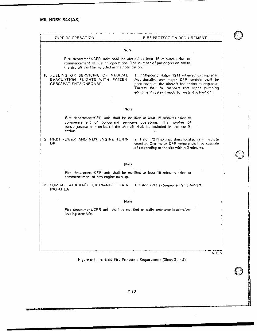
MIL-HDBK-844(AS)
TYPE OF OPERATION FIRE PROTECTION REQUIREMENT ()Note
Fire department/CFR unit shall be alerted at least 15 minutes prior tocommencement of fueling operations. The number of passengers on boardthe aircraft shall be included in the notification.
F. FUELING OR SERVICING OF MEDICAL 1 150-pound Halon 1211 wheeled extinguisher.EVACUATION FLIGHTS WITH PASSEN- Additionally, one major CFR vehicle shall beGERS/ PATIENTS ONBOARD positioned at the aircraft for optimum response,
Turrets shall be manned and agent pumpingequipment/systems ready for instant activation.
Note
Fire department/CFR unit shall be notified at least 15 minutes prior tocommencement of concurrent servicing operations. The number ofpassengers/patients on board the aircraft shal be included in the notifi-cation.
G. HIGH POWER AND NEW ENGINE TURN- 2 Halon 1211 extinguishers located in immediateUP vicinity. One major CFR vehicle shall be capable
.of responding to the site within 3 minutes.
Note
Fire depariment/CFR unit shall be notified at least 15 minutes prior tocommencement of new engine turn-up.
H. COMBAT AIRCRAFT ORDNANCE LOAD- 1 Halon 1211 extinguisher Per 2 aircraft.ING AREA
Note
Fire department/CFR unit shall be notified of daily ordnance loading/un-loading schedule.
N,2 85
Figure 6-4. Airfield Fire Protection Requirements (Sheet 2 of 2)
6-12

MIL-HDBK-844(AS)
D The first symptoms of the toxic effect of collects in the bottom of fuel tanks andbreathing fuel vapors are nausea, dizziness, and filter/separator often contains a high percentage (40headaches. If any of these symptoms are noted while to 60%) of fuel system icing inhibitor (FSII). Since.conducting fuel handling operations, personnel should the FSII materials used in JP-5, DiEGME andimmediately stop the operation and move to a fresh especially JP-4, EGME are considered toxic in a pureair location. If personnel are overcome by vapors, or concentrated state, exposure of personnel to waterthey should receive prompt medical attention. First bottoms of filter separators and tanks must be kept toaid procedures for personnel overcome by vapors the absolute minimum. If exposure occurs, washinclude removal to fresh air, treatment tor shock, and with soap and water followed by a thorough freshadministering of artificial respiration if breathing has water rinse. Disposal of water bottoms must bestopped. accomplished in accordance with local environmental
regulations.6.6.2 LEAD POISONING. The tetraethyl lead
which is added to all grades of aviation gasoline, is 6.6.6 SPECIFIC PROCEDURES FORvery poisonous. It is harmful if the vapors are AVOIDING TILE HEALTH HAZARDS OFinhaled or if the compound enters the body through AIRCRAFT FUELS. The NATOPS Aircraftthe mouth by skin contact. The principal danger of Refueling Manual contains a list of procedures whichlead poisoning occurs when it is necessary to enter or will minimize the dangers to the health of fuelrepair containers which have been used for leaded handling personnel.gasolines. Refueling and defueling personnelnormally will not have to do such work. but it isimportant that they be aware of the danger, and thatthey know never to enter a tank or vessel which hascontained leaded gasoline until the necessary safety
Sprecautions have been followed. The toxiceffect of tetraethyl lead may also occur fromprolonged exposure to gasoline vapors or liquids and,therefore, such exposure should be avoided. Anotherdanger from leaded gasoline is from the fumes givenoff by stoves or lanterns burning a gasolinecontaining tetraethyl lead. For this reason, leadedgasoline shall never he used for such purposes.
6.6.3 INJURY TO SKIN AND EYES.Aviation gasoline and jet engine fuels may 'causeirritation if brought in contact with the skin. For thisreason, direct skin contact with fuel should beavoided, If fuel is accidentally spilled on personnel.affected clothing should be removed immediately.Any skin areas exposed to fuel should be promptlywashed with soap and water. If a person accidentallygets gasoline or j:t fuel in the eyes, the fuel shouldbe immediately removed by rinsing them with plentyof water, Medical attention must be administered assoon as possible.
6.6.4 SWALLOWING AVIATION FUELS.Swallowing even sm,1ll amounts of aviation fuels isvery harmful and medical attention should beD obtained immediately.
6.6.5 FUEL TANK AND FILTER/SEPAR-ATOR WATER BOITOMS. The water that
6-13
S.... JtlW _ ~ ~ ~~~~-in, _ II IIIIl 11

MIL-HDBK-844(AS)
0
(This page intentionally left blank.) t-d
6-14

MIL-HDBK-844(AS)
APPENDIX A
VISUAL CONTAMINATION TABLE
A-1
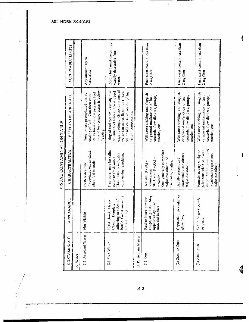
MIL- H DBK- 844 (AS)
1440 M t
00
wt
E~ .- r. r- '
< LL
0 u
C4C
LUU
u0
72 M
o ~ -o
A-2

MIL-HDBK-844(AS)
1: E
z. >
oj 0-1
u c t j
U~t -*t l
u 5: 33.0
ot 5d2 ej-> V,.4
~~ L
- -~ _ _A -3 0

MIL-HDBK-844(AS)
(This page intentionally left blank).
A-4

MIL-HDBK-844(AS)
Q APPENDIX B
PETROLEUM TESTING LABORATORIES
General. Aviation fuels require quality surveillance from the point of initial acceptance until they are actually usedin the aircraft. Every activity and individual in the supply system that transports, stores, distributes, or issues theseproducts is responsible for some phase of quality control. Two types of spnples are required to ensure quality fuelfor aircraft, these are Special and Routine. Definitions for each of these types of samples and procedures forfield personnel to follow in submitting them are contained in the following paragraphs.
Special Samples. These are samples which are submitted for testing because the quality of the fuel is suspecteither as a result of aircraft malfunctions or for other reasons.
Shipping Destinations: Special samples should be taken in duplicate and shipped to both the Naval AirWarfare Center, Aircraft Division, Trenton (NAWCADTRN) and to the nearest regional laboratory contained inthe list which begins on the next page. NAWCADTRN is available to assist field personnel worldwide in theidentification and resolution of quality problems and is responsible for determining the suitability of off-specification fuel for issuance to aircraft. NAWCADTRN's address and telephone numbers are listed in the tablebelow.
Sample size: Each laboratory will require a minimum quantity of one gallon. This means two one gallonsamples of fuel should be extracted from each problem location. Ship both samples by the fastest traceable means -the first gallon to NAWCADTRN and the second to the nearest regional laboratory.
Sample contains: Use the standard MIL-K-23714 specification red shipping containers.Documentation: When a fuel quality problem is encountered the activity should contact NAWCADTRN
via telephone immediately and follow up with a Naval message, telefax or letter which describes the problem andidentifies a point of contact. All samples should be properly labeled with all pertinent information (See paragraph3.3.3 or 9.3.3 in the Aircraft Refueling NATOPS Manual, NAVAIR 00-807-109).
Laboratory Shipping Address Lab Mailing Address
Naval Air Warfare Center Naval Air Warfare CenterAircraft Division, Trenton Aircraft Division, TrentonAttn: Code PE33 Attn: Code PE331440 Parkway Avenue P.O. Box 7176Trenton, NJ 08628-0176 Trenton, NJ 08628-0176
Telephone Numbers: DSN 442-7859 or commercial 609-538-6859DSN 442-7929 or commercial 609-538-6929
Telefax Numbers: DSN 442-7562 or commercial 609-538-6562DSN 442-7604 or commercial 609-538-6604
Message Address: NAVAIRWARCENACDIV TRENTON NJ//PE33// (Message must includeAccounting Symbol and Program Designator Code (AS/PDC) NA-CRAFAAimmediately after the list of addressees as discussed in paragraph 605 of the NTP 3message instruction.)
B-1

MIL-HDBK-844(AS)
Routine (monthly correlation) Samples. Routine Samples are the samples taken when no fuel problems oraircraft problems attributable to the fuel are known or suspected. These samples and their test results serve twopurposes:
I. They asist the activity in monitoring the performance of their local fuel testing equipment and methods.2. They provide TYCOM and SYSCOM cognizant offices with information on the general quality of thefuel delivered to aircraft and the performance of the fleet's quality control equipment.
The following laboratories are equipped to perform all tests required by aviation fuel specifications. Monthlycorrelation (routine) fuel samples should be shipped to the nearest or most convenient laboratory contained in thefollowing list. Fuel quantities and sample locations are described in the Aircraft Refueling NATOPS Manual,NAVAIR 00-80T-109. All samples should be properly labeled with all pertinent information (See paragraph3.3.3 or 9.3.3 in the Aircraft Refueling NATOPS Manual, NAVAIR 00-80T-109). Special samples (Seeparagraph on previous page) should be shipped to the closest laboratory annotated with an asterisk next to itslocation in the following list.
Location Laboratory Shipping Address Lab Mailing Address
SEast Coast
* Norfolk, VA Master Petroleum Laboratory Director, Fuel Department
Building W-388 Naval Supply CenterNorfolk, VA 23512-5100 Code 700
Norfolk, VA 23512-0700
Jacksonville, FL Director, Fuel Department (Same as Shipping Address)Navy Suppiy CenterCode 7008808 Somers RoadJacksonville, FL 32218-2600
" Searsport, ME Director, Aerospace Fuels Laboratory Det 20, SA-ALC/SFTLBDet 20, SA-ALC/SFTLB P.O. Box 408Trundy Rd, BId 14 Searsport, ME 04974-0408Searsport, ME 04974-0408
" Dayton, OH Director, Aerospace Fuels Laboratory Det 13, SA-ALC/SFTLA
Det 13, SA-ALC/SFTLA Wright-Patterson Air Force BaseArea B Bldg 70 Dayton, OH 45433-6503Wright-Patterson AFB OH 45433-6503
"* Tampa, FL Director, Aerospace Fuels Laboratory Det 21, SA-ALC/SFTLC
Det 21, SA-ALC/SFTLC P.O. Box 6051Bldg 1121 MacDill AFB, FL 33608-0051MacDill Air Force Base, FL 33608-0051
GB-2

MIL-HDBK-844(AS)
"Location Laboratory Shipping Address Lab Mailing Address
West Coast
* San Diego, CA Fleet and Industrial Supply Center Diretor, Fuel Department
Point Loma Subbase Naval Supply CenterBldg. 50 Code 700199 Rosecranes 937 North Harbor Dr.San Diego, CA 92106 San Diego, CA 92132
Seattle, WA Naval Supply Center Director, Fuel Department7501 Beach Drive Naval Supply CenterPort Orchard, WA 98366 Code 700
P.O. Box 8Manchester, WA 98353-0008
* Mukilteo, WA Director, Aerospace Fuels Laboratory Det 35, SA-ALC/SFTLD
Det 35, SA-ALC/SFTLD Ten Park Avenue C, Bldg 1Ten Park Avenue C, Bldg I Mukilteo, WA 98275-0046Mukilteo, WA 98275-0046
Pacific
* Pearl Harbor, HI Director, Fuel Department Director, Fuel DepartmentNaval Supply Center Naval Supply CenterCode 700 Code 700Pearl Harbor, HI 96860 Box 300
Pearl Harbor, HI 96860-5300
NOTE. NSC Pearl Harbor facilities should be used by units in theCentral Pacific.
Guam, Marianas Island Director, Fuel Department (Same as Shipping Address)U.S. Naval Supply DepotCode 700PSC 455Box 190FPO AP 96540-1500
Yokosuka, Japan U.S. Navy Fuel Depot Yokosuka, (Same as Shipping Address)Detachment Sasebo
PSC 476Box 7FPO AP 96322-1504
0B-3

MIL-HDBK-844(AS)
Location Laboratory Shipping Address Lab Mailing Address CNorth Atlantic
. Keflavik, Iceland Fuels Officer Commanding OfficerNAS Keflavik, IC U.S. Naval Air StationBox 32 Code 403PSC 1003 Box 32FPO AE 09728-0332 PSC 1003
FPO AE 09728-0332PSC 1003
* Suffolk, England UK Director, Aerospace Fuels Laboratory (Same as Shipping Address)
OL SA-ALC/SFTLFBldg 725RAF MildenhallAPO AE 09459
Mediterranean and Middle East
* Venice, Italy Director, Aerospace Fuels Laboratory (Same as Shipping Address)
OL SA-ALC/SFTLJBldg. 505Aviano AirbaseAPO AE 09601
Indian Ocean
* Diego Garcia Commanding Officer (Same as Shipping Address)
U.S. Naval Support FacilityCode 407Box 4FPO AA 96464-0004
Note: Additions, corrections or changes to the above lift should be forwarded to:
Naval Air Systems CommandAIR-5363CWashington, DC 20361-5360
8-4

"MIL-HDBK-844(AS)
APPENDIX C
AIRCRAFT INFORMATIONSUMMARIES
The following section provides general information about Navy andMarine Corps aircraft configurations, characteristics and requirementswhich can impact aircraft refueling operations. It is assembled here foruse by fuel handling personnel in general planning and other purposes.The information has been extracted from individual aircraft NATOPS Aircraft Manuals which must be consulted for the most accurate, up-to-dateinformation.0
Aircraft Page Number
A-6 ..................... .. C-2AV-8B ................... .. C-7E-21C-2 ................. .. C-12F-14 ................... .. C-16F-18 . ................... C-20S-3 . .................... C-25P-3 . .................... C-29H-I . .................... C-33H-2 ...................... C-37H-3 ...................... C-41H-46 . ................... C-45H-53 . ................... C-49
SH-60 . .................. C-54
0/
C-1
.7

MIL-HDBK-844(AS)
AIRCRAFT: A-6
AIRCRAFT CONFIGURATION
<a"
Tii
zw-0<
L3 __
5 ) -0 -0 _ _ _ _
000 zcc
0
0o .. .Z
w> w
0
00-z z w 0 0
C-2

MIL-HDBK-844(AS)
AIRCRAFT: A-6
TABLE OF FUEL CAPACITIES
Tank Gallons
Fuselage 1,344Internal Wing 1,028
Total Internal 2,372
300Drop Tank (Each)*
External .....
Air Refueling Store 300
* Two size. of tanks are available
AIRCRAFT CHARACTERISTICS
Aircraft Dimensions Aircraft Weight
Wing Span Maximum Gross WeightSpread 53 ft 74,350 lbs0 Folded 25 ft 4 in
Length 54 ft 9 in Maximum Footprint230 psi
Height 16 ft 2 in
A-6 REFUELING PROCEDURES
The following procedu~es cover only the refueling and "DROP TANKS" switches to "FUEL".procedures which are unique to the A-6 aircraft,primarily the operation of the "pre-check" system. In 2. On ground refueling panel access door, pressaddition to these specialized procedures, the applicable, "OUTER HIGH PRESS" indicator. All three "Highbasic refueling procedures contained in chapter 6 or 12 Pressure" indicator lights on the door should light.of the Aircraft Refueling NATOPS Manual, NAVAIR00-80T-109, must he followed. 3. On ground refueling panel, momentarily press each
"WING TANKS", "FUS TANKS", and "DROPTANKS" indicator that is not lighted; each indicator
WARNING shall light.
A-6 aircraft are normally hot refueled with CAUTIONboth engines operating. DO NOT ASSUMERIGHT ENGINE TURNED OFF untilconfirmation obtained. If indicators checked in steps 2 and 3
O malfunction, do not fuel aircraft.
1. Set "POWER" switch on ground refueling panel to
"FUEL", and set "WING TANKS", "FUS TANKS", 4. Attach refueling nozzle to aircraft receptacle and
C-3
......... 1%2 1 B MJl

MIL-HDBK-844(AS)
AIRCRAFT: A-6place nozzle flow control handle in the open position. 14. Set "POWER" switch to "OFF" on ground 0
refueling panel.5. Initiate fuel flow and monitor tank "High Pressure"lights on door above ground refueling panel.
SPECIAL NOTESCAUIONAIRCRAFT FUEL SYSTEM
., CAUTION
1. Under normal conditions, all air being displaced byfuel in the tanks, including external tanks, exits theImmediately stop fuel flow if any of the three 0
o y aircraft through the common "Fuel System Vent/Dump"High Pressure' indicators light during the0 0 Outlet".refuelirg operation. Cause of vent systemoverpressure must be corrected before fueling 2. If any high level shut-off valves fail to operateis resumed.2.Ianhihlvlsu-ofvlefaltopre "correctly, fuel may spill from the "Fuel System
6. Exercise pre-check system. Set and hold "SOL Vent/Dump Outlet' or the "Wing Tip Vents".
CHECK" switch to "PRI". All "WING TANKS PRI""FUS TANKS PRI', and "DROP TANKS PRI" 3. A malfunction within an external fuel tank may
indicator lights shal! go out and fuel flow into the cpause fuel to spill from the bo.om center of tank
aircraft stop prior to aircraft receiving 45 gallons of (pressure relief vent).
fuel.
7. When fuel flow stops, check flow rate. If flow rateexceeds 3 gallons per minute, discontinue hot refuelingoperation. Q8. On ground refueling panel, set "DROP TANKS"switches to "HOLD" and release "SOL CHECK"switch.
9. When fuel flow starts, immediately set and hold"SOL CHECK" switch to "SEC'. All "WINGTANKS SEC", and FUS TANKS SEC" indicator lightsshall go out and fuel flow automatically stop prior toaircraft receiving 30 gallons of fuel.
10. When fueling stops, check fuel flow rate. If flowrate exceeds 3 gallons or 20 pounds per minute, shutoff fueling unit and disconnect fuel nozzle.
1I. On ground refueling panel, set "WING TANKS"switches to "HOLD" and release "SOL CHECK"switch.
12. Fuel fuselage tanks until "FUS TANK" indicatorson ground refueling panel go out.
13. On ground refueling panel, set "WING TANKS"switches to "FUEL"; on aircraft with external tanks,set *DROP TANKS" switches to "FUEL" When"WING TANKS-, "FUS TANK", and "DROPTANKS" indicators are all out, aircraft is fueled.
C-4

MIL-HDBK-844(AS)
AIRCRAFT: A-6
GROUND REFUELING PANEL
TANK HIGH PRESSURE LIGHTS
wi:W TAP iKA i I
oma o~r.&A
wil.,, T NK
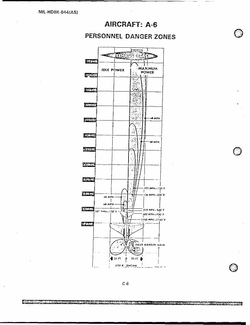
MIL-HDBK-844(AS)
AIRCRAFT: A-6
PERSONNEL DANGER ZONES0
IDLE POWER -.MAXIMUMOWER
48 MPH
64 MPH
10?MPH-10F
-- 136 MPH-200'F48MPH
68 MPH - _
Il,410 )'-53F
6U2 MPH-700* F
- 160 MPH-1 1604
'K Nt f 7 ANGE2 AREA
IS rY 25 FT.
C-6

MIL-HDBK-844(AS)
AIRCRAFT: AV-8B
AIRCRAFT CONFIGURATION
*0 I
ni
z f
z D1F-J
zzwD
U-0
0 M
w z
00
u-<
-JJ D Mcr0
00D D
F-w
0--
~Lmmn 0

MIL-HDBK-844(AS)
AIRCRAFT: AV-8B
TABLE OF FUEL CAPACITIES
Tank Gallons
Fuselage Left Tank 47
Left Front 80
Right Front 80Internal
Right Center 47
Rear 162
Wing Left 362
Right 362
Total Internal 1,140
External Tanks (Each) 300
With 2 External Tanks 1,720Totals With 4 External Tanks 2,328
AIRCRAFT CHARACTERISTICS
Aircraft Dimensions Aircraft Weight
Wing Span Maximum Gross WeightSpread 30 ft 4 in 21,500 lbs
Length 46 ft 4 in Maximum Footprint
Height l Ift 9 in 115 psi
AV-8B REFUELING PROCEDURES
The following procedures cover only the refueling 2. Open door 22.procedures which are unique to the AV-813 aircraft,primarily the operation of the "pre-check" system. 3. Press-to-test "TANK OVER PRESS" warningIn addition to these specialized procedures, the light on ground refueling panel for lamp operation.applicable, basic refueling procedures contained inchapter 6 or 12 of the Aircraft Refueling NATOPS 4. Set "LEFT" and "RIGHT REFUEL" switchesManual, NAVAIR 0o-80T1-09, must be followed, on the ground refueling panel (door 22) to the
"REFUEL" position (toggles down) and startI. Remove receptacle cap and attach refueling refueling.nozzle.
5. Make sure "LEFT" and "RIGHT FUEL
C-8

MIL-HDBK-844(AS)
SAIRCRAFT: AV-8B
CONTENTS" lights are on. 9. Watch the "LEFT" and "RIGHT FUELCONTENTS" lights. When the lights go off, theaircraft is full. Immediately stop fuel flow and
CAUTION close and lock the nozzle's flow control handle.
10. Set "LEFT" and "RIGHT REFUEL" switches* If any of the three lamps fails to t lgtpsto tglsu)
operate in steps 3 and 5 above,
discontinue refueling operation Note: If any of the high level shut off valves fail toimmediately. System failure must operate correctly, fuel will spill from the vent mast.Sbe investigated and resolved Turn off fuel flow immediately!before hot refueling can beaccomplished. SPECIAL NOTES
AIRCRAFT FUEL SYSTEM6- 6 Fuel can be stopped from entering the external
,tanks by setting "EXT TANK LOCKOUT" switch 1. This aircraft is NOT equipped with a pre-checkto "LOCKOUT" position. system.
I. Monitor t.he "TANK OVER PRESS" warning 2. Under normal conditions, all air being displacedlight, by fuel in the tanks, including external tanks, exits
the aircraft through the common "Fuel Vent Mast".
CAUTION'1 3. If any high level shut-off valves fail to operate
Immediately ,top fuel flow if correctly, fuel may spill from the "Fuel Vent
"TANK OVER PRESS" indicator Mast".lights. "Hot refuefini" cin not beperformed on the aircraft until 4. A malfunction within an eaternal fuel tank may
problem is resolved, cause fuel to spill from the bottom center of tank(pressure relief vent).
8. After 60 to 120 gallons of fuel have entered theaircraft's tanks, make sure air is venting fromFUEL VENT MAST.
C-9
.... '- \

MIL-HDBK-844(AS)
AIRCRAFT: AV-8B
GROUND REFUELING PANEL
7- ~ BOOST
\R
" /... . .... PUMPEXT TANK LEFT RIGHT
LOCKOUT L REFUEL .
OOOR 22 *. 161573 THRU 16158.
EXCEPT 161576
* >...: 1 BOOST
LFFT FIGHT TANK . . " ,R
0 00 PUMPLFUEL CON TENTS' OVER TTNK LTRIH
PRESS
EXTERNAL FUEl LOCKOUT L__EFUEL_CONTROL PANEL 162068 THRU 162973
ASSEMBLY "' I~, 6 , - .,
;J., .*. ~ " .- , - S
EXT TA¶NK U'
161576, 163'7.6 AND UP
c-I iJ

MIL-HDBK-844(AS)
AIRCRAFT: AV-8B
PERSONNEL DANGER ZONES
I.'1 I'N I)
L DANGER AREAAVOID AREATO PREVENTFOREIGN OBJECTDAMAGE fFO0)
SAFE 50FT
450 AREA 200 APPROX
WARNING 2 SF
I AREA
Areas immediately alt
and adjacert to IDLE POWER NOZZLESthrust nozzles, and FULL AFT TO 100 DOWNforward and adjacent
to engine intakes must Safe area is sale fr maintenance when
be avoided, engine is idling and nozzles are alt(0* to 10t nozzle deflectioni
Personnel shouldavoid being out 31 the
pilot's view duringvertcaI take-oil.vertical landing of _________________
hovering unless theyare by a flixed 80 FTobstruction known .._....
to the pilot.40 FT
A. Temoerature drops to 500C.
8. Danger horn ilying stones and 125 FT Aearth. Speed drops to 30 knots. 150 Fo T _ _ 8
THROTTLE SET ABOVE IDLENOZZLES FROM FULL AFT TO 450
\~50 FT
A. Temperature drops to 50C. - t25 FT - A.
B. Danger from flying stones and 150 FT- 8.earth. Speed droos to 30 knots.
THROTTLE SET ABOVE IDLENOZZLES FROM 450 TOFULL DOWN
THROTTLE SET ABOVE IDLENOZZLES DOWN
C-i1

MIL-HDBK-844(AS)
AIRCRAFT: E-2 / C-2
AIRCRAFT CONFIGURATION
TANK PRESS RELIEF VALVES
TANK PRESSURERELIEF VALVES
FUEL SYSTEM VENT/ -'DUMP PORT (C-2) FUEL SYSTEM VENT,
DUMP PORT (E-2)Sites of posiblefuel spills
ELECTRICAKE GRONDNG
BONDIN N PO IN T
ELECTELECTRGCALNGRO U N DIN G!
BONDING POINT
BONDING POINT
GROUND REFUELING PANEL
AND RECEPTACLE
C- 12

7
MIL-HDBK-844(AS)
o AIRCRAFT: E-2 1 C-2
TABLE OF FUEL CAPACITIESTank Gallons
Left 912
Wns Right 912
Total Internal 1,824
AIRCRAFT CHARACTERISTICS
Aircraft Dimensions Aircraft Weight
Wing Span Maximum Gross WeightSpread 80 ft 7 in 53,000 lbsFolded 29 ft 4 in
Length 57 ft 7 in Maximum Footprint
Height 18 ft 4 in 260 psi
E-2 / C-2 REFUELING PROCEDURES
The following procedures cover only the refuelingprocedures which are unique to the E-2 / C-2 aircraft, [ AU I ]primarily the operation of the "pre-check" system. Inaddition to these specialized procedures, the applicable,basic refueling procedures contained in chapter 6 or 12 0 Discontinue Hot Refueling operationof the Aircraft Refuel-ng NATOPS Manual, NAVAIR immediately if "NOT FULL" lights
00-80T-109, must be followed, fail to illuminate.
r Ensure that vent at tail of aircraft isWARNIG clear and that tanks are venting
during fueling. If no venting isindicated, cease fueling operation
E-2 aircraft are normally hot refueled with both immediately.engines operating. DO NOT ASSUMERIGHT ENGINE TURNED OFF until 3. Hold left "TANK PRECHECK" switch toconfirmation obtained. "PRIMI". After the left "NOT FULL" light goes off
(approximately 3 seconds later) hold the right "TANK
1. Open "PRESS FUEL STA" access door. PRECIIECK" switch to "SEC". After the right"NOT FULL" light goes off fuel flow into the aircraft
2. Remove receptacle cap, attach refueling nozzle, should stop.open nozzle to the fully open and locked position andinitiate fuel flow. "NOT FULL" lights on pressure 4. Release switches and fuel flow should resume.
0fueling station should illuminate. 5. Repeat the precheck process in step three above,this time holding the left "TANK PRECHECK"
C- 13

MIL-HDBK-844(AS)
AIRCRAFT: E-2 / C-2switch to "SEC" and the right "TANK PRECHECK"switch to "PRIM". WARNIG ]
C Aircraft should not be completelyfilled during hot refueling operationssince failure of a high level shut-off
0 If fuel flow does not stop when valve will result in fuel flowing out"NOT FULL" lights go off in either of the pressure relief valve and ontostep 3 or 5 above, discontinue hot a engine exhaust pipe.refueling operation immediately.System failure must be investigated SPECIAL NOTESand resolved before hot refueling can AIRCRAFT FUEL SYSTEMbe accomplished.
1. Under normal conditions, all air being displaced by6. Release switches and refuel aircraft until pilot gives fuel in the tanks exits the aircraft through the commonhand signal indicating aircraft is full or he wishes "Fuel System Vent/Dump Port" (in the tail on the E-2refueling terminated. and on the fuselage on the C-2).
2. If any high level shut-off valves fail to operatecorrectly, fuel may spill from special pressure reliefvalves on the tops of the wings.
C
GROUND REFUELING PANEL
• - .. . . . .. . , . • , .;-~
NOT FULL. •• ". ~~LIGHTS """:;
ENG IN E"•.•e'.
STRAINER BYPASSL I GHTS 7"-:•,h-''
P• '":i' ;"LEFT AND RIGHT"F FELING ."TANK PRECHECK
ADAPTER CAP SWITCHES
7$4 i2
..... 1 ,4.
C- 14

MIL-HDBK-844(AS)
o AIRCRAFT: E-2 / C-2PERSONNEL DANGER ZONES
.... .... . .. .
504?F-2S I 10 T/S
13-F7 _TS 1-ý. A t *F15 ISE
.. . . . . ....... .. . .. . .. . .900 -520 FrSE
c-i" 5zi,9
tz
1. .1
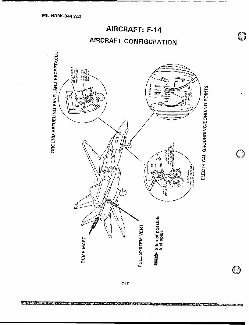
MIL-HDBK-844(AS)
AIRCRAFT: F.-14o
AIRCRAFT CONFIGURATION
C-,
x ou
CL,
z ___
/1 0
zz00crr0
clr
0
U- w
a.,
D w
W-16
MCi mugNIN

MIL-HDBK-844(AS)
AIRCRAFT: F-14
TABLE OF FUEL CAPACITIES
Tank __ Gallons
Forward 691
Aft 648
Fuselage Right Feed 235
Internal Left Feed 221
Left 295Wing Right 295
Total Internal 2,385
Total External 534
Total Capacity 2,919
AIRCRAFT CHARACTERISTICSAircraft Dimensions Aircraft Weight
Wing Span Maximum Gross WeightSpread 64 ft PA in 74,349 lbsFolded 38 ft 2½A in
Length 62 ft 8/ in Maximum Footprint
Height 16 ft 1 in3145 psi
F-14 REFUELiNG PROCEDURES
The following procedures cover only the refuelingprocedures which are unique to the F-14 aircraft, CAUTIONprimarily the operation of the "pre-check" system. Inaddition to these specialized procedures, the applicable,basic refueling procedures contained in chapter 6 or 12 Immediately stop fuel flow ifof the Aircraft Refueling NATOPS Manual, NAVAIR indicator moves to "STOP FUEL" or00-80T-109, must be followed, red position.
1. Attach refueling nozzle to aircraft and place nozzle 3. Exercise pre-check system by switching both theflow control handle in the open position. "FUSE TANKS" and "WING EXT TANKS" handlesto the "STOP FUEL" position. Fuel flow into the
2. Initiate fuel flow and observe vent pressure gage on aircraft should stop within a few seconds.ground refueling panel.
C-17
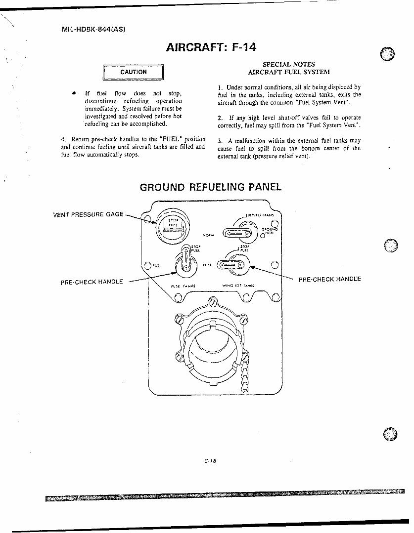
MIL-HD3K-844(AS)
AIRCRAFT: F-14SPECIAL NOTES
CAUTI[ONEl AIRCRAFT FUEL SYSTEM
1. Under normal conditions, all air being displaced byIf fuel flow does not stop, fuel in the tanks, including external tanks, exits thediscontinue refueling operation aircraft through the common "Fuel System Vent'.immediately. System failure must beinvestigated and resolved before hot 2. If any high level shut-off valves fail to operaterefueling can be accomplished, correctly, fuel may spill from the "Fuel System Veni".
4. Return pre-check handles to the "FUEL" position 3. A malfunction within the external fuel tanks mayand continue fueling until aircraft tanks are filled and cause fuel to spill from the bottom center of thefuel flow automatically stops. external tank (pressure relief vent).
GROUND REFUELING PANEL
VENT PRESSURE GAGE f.'Qfl/RAS
PRE-CHECK HANDLE PRE-CHECK HANDLE
0C- 18
I II II II II MII OMII =

MIL-HDBK-844(AS)
AIRCRAFT: F-14
PERSONNEL DANGER ZONES
IDLE POWER10.0
2. VELOCITY FT/SEC5.0 2• 0150 -
0 0152.5 \\2oV-6
100F~ L ... .. . ......... _ •
25s.. ---f--). TOTAL TEMPERATURE..10.0i
0 100 200 400 400 500
DISTANCE FROM DISTANCE FROM NOZZLE EXITNOZZLE AXIS-FT ENGINE EXHAUST DANGER AREA 120 FEET
MILTARY POWERAT HIGH TRUST SETTINGS.THE SUCTION DANGER 15 60AREA AROUND ENGINEINLETS MAY EXTEND AS VELOCLTYDFAR AS 4 FEET AFT OF IFT/SEC
'THE INLET DUCT LOWERLIP.
2 00-0 1- _EOO 200.
20------------- - - - . -- 0
TEMPEHATURE 'F
0 100 200 300 400 500
DISTANCE FROM DISTANCE FROM NOZZLE EXITNOZZLE AXIS-FT ENGINE EXHAUST DANGER AREA 1100 FEET
.
c- 19
Ip

MIL-HDBK-844(AS)
AIRCRAFT: F-18o
AIRCRAFT CONFIGURATIONELECTRICAL GROUNDING/BONDING POINTS
IGROU LNO INGRECEPTACLE WING PYLONS
MAIN LANOING GEAR
WING PYLONS NOSE LANDING HEWL(2AGEAR WHEELWELL
GRO UNDING
RECEPTACLE- ~~ GROUND LE FT SID0E SI- OWN
-, RECEPTACLE RIGHT SIDE TYPICAL
NOSE LANDING GEAR WHEELWELL '~Y-'-
MAIN LANDING GEAR WHEELWELL
C-20

MIL-HDBK-844(AS)
AIRCRAFT: F-1 8
AIRCRAFT CONFIGURATIONLOCATION OF VENTS AND DUMP MASTS
FUEL SYSTEM VENTS
~FUEL DUMP PORTS
MG-T[.G. EZ Sites of possible
Vew, Outles are on1 the side of each tail whichis furthest from the ce4,ter-tire of the aircraft.
V VENT OUTLET
.1 side -i the sarne)
GROUD RFUEIING PANEL AND RECEPTACLE
A-
a DOOR 8 SINGLE POINT
GROUNDREFUEL/DEFUELRECEPTACLE
GROUND REFUELINGRECEPTACLE CAP

MIL-HDBK-844(AS)
AIRCRAFT: F-18
TABLE OF FUEL CAPACITIES
Tank Gallons
Fuselage Number 1 418
Number 2 263
Number 3 206Internal
Number 4 532
Wing Left 85
Right 85
Total Internal 1,589
Elliptical Wing or 314Centerline Tank
ExtemaJ Cylindrical Wing or 330
Centerline Tank
AIRCRAFT CHARACTERISTICS
Aircraft Dimensions Aircraft Weight
Wing Span Maximum Gross WeightSpread 40 ft 5 in 51,900 lbsFolded 27 ft 6 in
Length 56 ft Maximum Footprint
Height 15 ft 3 in 315 psi
F-18 REFUELING PROCEDURES
The following procedures cover only the refuelingprocedures which are unique to the F-18 aircraft, CAUTIONprimarily the operation of the "pre-check" system. Inaddition to these specialized procedures, the applicuble,basic refueling procedures contained in chapter 6 or 12 F-18 aircraft are normally hotof the Aircraft Refueling NATOPS Manual, NAVAIR refueled with both engines operating.00-80T-109, must be followed. DO NOT ASSUME RIGHT
ENGINE TURNED OFF untilconfonation obtained.
I. Attach refueling nozzle to aircraft and place nozzleflow control handle in the open position.
C-22

MIL-HDBK-844(AS)
QAIRCRAFT: F-18
2. Initiate fuel flow and observe tank pressure gage onground refueling panel. CAUTIO
CAUTION If fuel flow does not stop,discontinue refueling operationimmediately. System failure must be
0 Immediately stop fuel flow if tank investigated and resolved before hotpressure gage indicates increasing refueling can be accomplished.pressure.
4. Return "Master Precheck Handle" to the down (off)3. Exercise pre-check system by moving the "Master position and continue fueling until aircraft tanks arePrecheck Handle" into the up position. Observe "Fuel filled and fuel flow automatically stops.Flow Indicate" movement to verify that fuel flow intothe aircraft stops.
SPECIAL NOTESa. No external tanks instalted. Fuel flow into the AIRCRAFT FUEL SYSTEM
aircraft should stop in approximately 45 seconds.1. Under normal conditions, all air being displaced by
b. External tank(s) installed. Wait approximately' fuel in the tanks, including external tanks, exits the45 seconds, then press the "Ext Tk" button on the aircraft through the common "Fuel System Vent"."Fuel Check Panel". Fuel flow into the aircraft shouldstop within approximately 10 seconds. 2. If any high level shut-off valves fail to operate
correctly, fuel may spill from the "Fuel SystemVents".
3. A malfunction within an external fuel tank maycause fuel to spill from the bottom center of tank(pressure relief vent).
GROUND REFUELING PANEL
"TANK PRESSURE/FUEL FLOWINDICATOR
* ELECTRICALGROUNDINGJACK ~-
161353 thru 161761
MASTER PRECHECK FUEL CHECKHANDLE PANEL
C-23

MIL-HDBK-844(AS)
AIRCRAFT: F-18
PERSONNEL DANGER ZONES
- - - 20 ELECTROMAGNETIC RADIATIONIMPACTi--POINT
I IMPACT31 FT POINT
34 FTT
INLET. SUCTION-I NTER MEDIATE[ DR AB
IDLE POWERXL 8 FOOT RADIUS57
TURBINESBLADE FAILUIRE
APU EXHAUST___________APU EXHAUST
AT 100 FT168 FT48f- _ _
I900 FT '\_
MISSI LEEXHAUST V7 -
C-24

MIL-HDBK-844(AS)
AIRCRAFT: S-3
AIRCRAFT CONFIGURATION
EXT TANK VENT---A
FUEL SYSTEM VENT! X AKVNDUMP PORTS/EXT TANK VENT
RECEPTACLE SAFING DOOR
GROUND REFUELING PANEL
El J - Sites of possible0fuel spills
FUEL SYSTEM VENT/DUMP PORTS
ELECTRICAL GROUNDING!BONDING POINT
(D C~ONN CC OR
CAUIONRECEPTACLE Inside Right BE 0,PAN I NOMRSN
Main Wheel Well
GROUND REFUELING PANELELECTRICAL GROUNDING/0 BONDING POINT
C-25

MIL-HDBK-844(AS)
AIRCRAFT: S-3/
TABLE OF FUEL CAPACITIES
Tank Gallons
Left Feed 176.5
Right Feed 176.5
Left Transfer 790.0' Internal Right Transfer 790.0
_ _ Total Internal 1,933.0
External Left Pylon 265.0
Right Pylon 265.0
Total Internal + External 2,463.0
AIRCRAFT CHARACTERISTICS
Aircraft Dimensions Aircraft Weight
Wing Span Maximum Gross WeightSpread 68 ft 8 in 50,000 lbsFolded 29 ft 6 in
Length 53 ft 4 in Maximum Footprint
Height 22 ft 9 in 288 psi
S-3 REFUELING PROCEDURES
The following procedures cover only the refueling 1. Attach refueling nozzle to aircraft and place nozzleprocedures which are unique to the S-3 aircraft, flow control handle in the open position.primarily the operation of the "pre-check" system. Inaddition to these specialized procedures, the applicable, 2. Initiate fuel flow and observe "TANK PRESSUREbasic refueling procedures contained in chapter 6 or 12 INDICATOR GAUGE" on ground refueling panelof the Aircraft Refueling NATOPS Manual, NAVAIR (inside the right main landing gear wheel well).00-80T-109, must be followed.
CAUTION
CAUTION* Sonobouy Safing Door must be
opened to insure that the jetisonsystem has been disarmed. 0 Immediately stop fuel flow if
indicator moves into the red band
C-26

MIL-HDBK-844(AS)
AIRCRAFT: S-3labeled "STOP REFUELING". 5. If external tanks are installed, they can be refueled
by turning the "EXTERNAL TANK FUELING3. Exercise precheck system by twisting and holding SWITCH" to the "ON" position. This switch shouldboth "PRECHECK VALVES" on the ground refueling be placed in the "ON" position only after the high levelpanel in the "OPEN" position. Fuel flow into the shutoff valves in the internal tanks have been testedaircraft should stop within 20 seconds. using the "PRECHECK VALVES" in steps 3 and 4
above. Return this switch in the "OFF" position at theconculsion of the refueling operation.
CAUTION
SPECIAL NOTESAIRCRAFT FUEL SYSTEM
If fuel flow does not stop,
discontinue refueling operation 1. Under normal conditions, all air being displaced byimmediately. System failure must be fuel in the internal tanks exits the aircraft through theinvestigated and resolved before hot common "Fuel System Vent Port".refueling can be accomplished.
2. If any high level shutoff valves fail to operate"4. PRECDiiECK VALVES" are spring loaded to the correctly, fuel may spill from the "Fuel System Vent"CLOSED" position. Release tht~m and continue Port" and/or tank(s) may rupture.
fueling until aircraft tanks are filled and fuel flow
automatically stops. 3. A malfunction within the external fuel tanks may
cause fuel to spill from the bottom center of theexternal tank (pressure relief vent).
140 4. The Precheck system does not exercise the highlevel shutoff valves in the external tanks.
GROUND REFUELING PANEL
TANK PRESSUREINDICATOR GAGE
SELECTRICAL GROUNDING! /~@ BONDING POINT
RIGHT AND LEFTPRECHECK VALVES
EXTERNAL TANKFUELING SWITCH
REFUELING RECEPTACLE
inside RightMain Wheel Well
C-270: • "'5- " •-•o• rII ~
"-C.2

MIL-HDBK-844(AS)
AIRCRAFT: S-3
PERSONNEL DANGER ZONES
HAZARDOUS GROUND OPERATIONS
CANOPY AND HATCHEXPLOSIVE SEVERANCE RADAR RADIATION IS HAZARDOUS
APU EXHAUST HAZARD WITHIN THE DISTANCES NOTED.
FULL POWER:ENS HAIARDOUENGINE INLET FUELING EQUIPMENT/FUEL TANKS
PERSONNEL
26 FT 23SFT
RADIUS200 FT
0 FFT
TIRE EXPLOSION TIRE EXPLOSIONAND TUR8INE AND TURBINESLADE HAZARD BLADE HAZARD WR
RADAR RADIATION AT fULL POWER. WITH THEBK1B-10l RADAR INH181TOR PLUG INSTALLED,IS HAZARDOUS TO PERSONNEL. FUEL EQUIPMENT,AND FUEL TANKS CLOSER THAN 50 FEET.
ENGINE BLAST AND TEMPERATURE AREAS
20 MPH 40 70 135 270 400 6W)287 FT MPH MPH MPH MPH MPH MPH
2<0 4,0 70 M PH 1 10 =MPH MPH MPH MPH /
ESTIM ATED J ET WAKE--PROFILESMA • P ER OWER .
WOF" 551fF3502 5"F15f
C-28
MP f

MIL-HDBK-844(AS)
AIRCRAFT: P-3
AIRCRAFT CONFIGURATION
FUEL SYSTEM VENT PORTPORT
0
F I SPLL
F FILLER
AFT LOWER END OF /NO. 3 ENGINE NACELLE/
Q GROUND REFUELING PANELAND RECEPTACLE
FUEL SYSTEM VENT PORT
SITES OF POSSIBLEFUEL SPILLS
FUEL SYSTEM VENT PORT
C-29
~ I I ~ 2J*'~I~1iEU/

MIL-HDBK-844(AS)
AIRCRAFT: P-3
TABLE OF FUEL CAPACITIES
Tank Gallons
No. 1 1,606Outboard
No. 4 1,606
No. 2 1,671Inboard
_No. 3 1,671
No. 5 2,646
Total Internal 9,200
AIRCRAFT CHARACTERISTICS
Aircraft Dimensions Aircraft Weight
Wing Span 99 ft 8in Maximum Gross Weight139,76G lbs
Length 116 ft 10 in Maximum Footprint
Height 34 ft 3 in 250 psi
P-3 REFUELING PROCEDURES
The following procedures cover only the refueling *FUEL SYSTEM VENTS". If noprocedures which are unique to the P-3 aircraft, venting is indicated, cease fuelingprimarily the operation of the "pre-check" system. In operation immediately.addition to these specialized procedures, the applicable,basic refueling prccedures contained in chapter 6 or 12 3. Locate the Precheck system valve test switches onof the Aircraft Refucling NATOPS Manual, NAVAIR the ground refueling panel. Hold left00-80T-109, must be followed. "VALV CONT" switch to "PRI CLOSE" and the
right "VALV CONT" switch to "SEC CLOSE". Fuel1. Open Ground Refueling Panel access door. flow into the aircraft should stop within a few seconds.
2. Remove receptacle cap, attach refueling nozzLt, 4. Release switches and fuel flow should resume.open nozzle to the fully open and locked position, andintiate fuel flow. 5. Repeat the precheck process in steop three above,
this time holding the left "VALV CONT" switch to"PRI CLOSE".
WARNING
0 Ensure that air is venting from QC-30

MIL-HDBK-844(AS)
SAIRCRAFT: P-3 SPECIAL NOTES
[ CAUJTION AIRCRAFT FUEL SYSTEM
I. Under normal conditions, all air being displaced byIf fuel flow does not stop step 3 c. 5 fuel in the tanks exits the aircraft through the commonabove, discontinue hot refteling "Fuel System Vent Port" which is located on each sideoperation immediately. System of aircraft.failure must be investigated andresolved before hot refueling can be 2. If any high level shut-off valves fail to operateaccomplished. correctly, fuel may spill from one of the "Fuel System
Vent Port*. In 'addition, the fuel tanks, which are6. Release switches and refuel aircraft until fuel flow located in the Stubwings, may rupture and spill fuel.
into the aircraft stops and the fuel quantity gage on the
ground refueling panel indicates the tanks are full.
GROUND REFUELING PANEL
FF I LLER
AFT LOWER END OF7NO. 3 ENGINE NACELLE
C-31

NllL-HDBK-8441,AS)
AIRCRAFT: P-3PERSONNEL DANGER ZONES
SIC(TCANTENNAS ROTATE 360 DEGREES
THET EAM MNAY EXTEND BEYOND THE 18OA A DGREE A RE A SHOWN SAFE AREAS H AVE
VIuRBINE ANO N OTr BEEN DETERMINEDPROP PELLER SLADEFAILURE OANCGERAREA
PROPELLERDANIGER FROM BLAST IMPELLED
PAROPELLE ROCKS AND0 DIRT 1500O FEETSTRIPf
14.0FOOT 10
RA(I 140 EDDY ¶ 4 N
THROUJGH FOOTIU180DE 'THOUGH
ISO DEREES J
.DO NO0T APPLY HIGH VOLTAGE TORADAR ANTENNA WTTH AM TrTR4MMYLO..f SWATCH Of ANT POSITION WHENFUECL TRUCXS OR FUELING OPERATIONSAMC WITHIN A RADIUS OF 140 FEET FROM
100 FT100 FTRADAR ANTENNA.N, . PERSONNEL MUST SE WARNED TOT100 FT STAY 7S FEET FROM A RADA.R AAE
LESSTHA 90dh-TENNIA. WH-EN H~IG VOLTAOE IS AP-PEIED AND ANTENNA BS SEE CTE 1D.
dN T-RGUO 120'\ 0 CFFET FOA TEN AIIJAPS 137MV 2)
R"O\~f>. mco HARD jbC ODI ICMLST REMAAIN AT
'>'~ ' v~~1O d TO1~I d ~'" AK~4•~/ ~ ~ K~~KTEmNA WHENNMHIGHVOLTAGES MAP-
OTIECtý- 94 FEET F0OR THE AXIAPS 137 M Z
- ¾>N~\NOTE
'j''~2 S AlA~.<';N/,)$4 ;;/.TO ACCURATELY ASSESS TNE EFFfCTIVE4,4 / I-~*~ ~f NESS Of HEARING CONSERVATION* .//,', <" ~ oL 1'~'jj'~""' ~MEASURES ALL PERSONNEL EXPOSEDO'"- /~/' ---- 0 TO NOSE HAZAADIOUS AREA SHOULDO0
A(CitE! ROUTINE MON-ITORINGAvIOIOIE TRY WI ACCORDANCE WITH
- // " Y'OPNAVINST 6260 6 SERIES
/ // / ">K~ ~ ~, , / , ~S0JOUN INTENSITY LEVELS OF .1 .. A AND/ 4 / 'PRmbR HAIVE SEEN REfCORDED RISICX P 3_________ ~ ,4AIRCRAFT DURING FLIGIAO CONSIDEAA________- /~/X //// i00 SHOULDO RE GIVEN TO WEARING
______ _______ / / - ~N~' HEARING PROTECTION *HiLE DEEHEADSEt. AS UNPROTECTED EXPOSIJBE
N'~'N~" "'MAY RESULT IN TEMPORARYT DL '(AMA~Q» \~>x\SENET NEARING LOSS
~ ~4<\ ~'4N IA COMBINATION OF PISCOT AND CIS.______140 dE, AND ABOVE DANGERt 0 CUqARA SNEARN PROUTIZECTIONEVEN WITH EAR PROTECTION p;4<\\ ODTONO EIE ED4L EUIIE IR
LIo.UT EXPOSURE TO ABSOCuTE 4 EN11C AT YDLVESECED0
100F I t~ , Y'INMUMTAKEOJEF POWER
C-32

MIL-HDBK-844(AS)
AIRCRAFT: H-i
AIRCRAFT CONFIGURATION
.0
t V
0 -a r- z )
in: F1( . ->-~ -c~ -- ' UJ
w .5 t
IIu
0L -0C
oz
zz
(JLcc 3j
~~~ 0 ~

MIL-HDBK-844(AS)
AIRCRAFT: H-1
TABLE OF FUEL CAPACITIESTank Gallons
Forward 190
Internal Aft 123
Total 313
External Wing 2 Maximum 100Tanks (each) 4 Maximum 77
AIRCRAFT CHARACTERISTICS
Aircraft Dimensions Aircra't Weight
Fuselage Maximum Gross WeightWidth 10 ft 9 in 14,750 lbs
Length 58 ft Maximum Footprint
Height 14 ft 2 in 70 psi
0H-1 REFUELING PROCEDURES
The following procedures cover only the refueling of the "PRECHECK" plungers on the rim of dieprocedures which are unique to the H-I aircraft, fueling valve. Fuel flow into the aircraft should stopprimarily the operation of the "pre-check" system. In within 20 seconds. Release the "PRECHECK" plungeraddition to these specialized procedures, the applicable, and fuel flow should resume into the aircraft.basic refueling procedures contained in chapter 6 or 12of the Aircraft Refueling NATOPS Manual, NAVAIR 3. Repeat the last step this time holding the other00-80T-109, must be followed. "PRECHECK" plunger down.
I. Remove receptacle cap, attach refueling nozzle,open nozzle to the fully open and locked position, and WARNINGinitiate fucl flow.
Flow of fuel while either of theWARNING "PRECHECK" plungers are held
down indicates a failed shutoff valve.Stop refueling immediately. System
Ensure that air is venting from failure must be investigated and"FUEL SYSTEM VENTS". If no resolved before hot refueling can beventing is indicated, cease fueling accomplished.operation immediately.
4. Release both "PRECHECK" plungers and refuel2. Exercise the Precheck system. Press and hold one aircraft.
C.34
,~ ~ ~ ~ ~ ~~2 ,5 ,II III II1
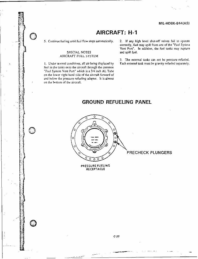
MIL-HDBK-844(AS)
AIRCRAFT: H-i5. Continue fueling until fuel flow stops automatically. 2. If any high level shut-off valves fail to operate
correctly, fuel may spill from one of the "Fuel System"Vent Port". In addition, the fuel tanks may rupture
SPECIAL NOTES and spill fuel.AIRCRAFT FUEL sYSTEM
3. The external tanks can not be pressure refueled.1. Under normal conditions, all air being displaced by Each external tank must be gravity refueled separately.fuel in the tanks exits the aircraft through the common"Fuel System Vent Port" which is a 3/4 inch AL Tubeon the lower right hand side of the aircraft forward ofand below the pressure refueling adapter. It is almoston the bottom of the aircraft.
4. GROUND REFUELING PANEL
0 00 0
0 0
0 0 PRECHECK PLUNGERS
PRESSURE FUELINGRECEPTACLE
C-35'F
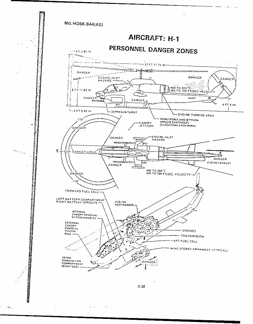
MlL-HD8K..s4(AS)
AIRCRAFT:H-
F 385iN PERSONNEL DANGERZOEFTE 38ONES
-57 FT 1 175 IN
HDANGER--H - - - E.NGi.,4E I NLET
HAZARD AGRDNE
li-300 TO 100 TSCV L IY8 FT 183 IN/ P A N G E R L I ) D A N G E R4
F T 8 N
L; 3 FT 9 40 IN 20 MM GUN TURRETENIETRNEA A
110'WING STORES ANO JErT-SONANOPY IMPULSE~ CA RTRIDGES
DA GE ETTISO N Q~ LOCATIONSj EACH WING)
DANGER .,-ENGINEINE
t FORWARD FUALZCEL
LE UN ATT ERY CMAR MENARIGHT BATT RY OP OSIT HDANAGER
ENGIENESAUS
DANGE 300IN STRE 100M.~ F TYPICALLCIT
L-TBTEYCOMPARTM ENT ALODAGERA(RIGHT SATDERYOPST
/ETANE
f! INTER36
CAOYRMVL

MIL-HDBK-844(Al
AIRCRAFT: H-20 AIRCRAFT CONFIGURATION
oz
x~ 0ca z
0IUD
/ -J
> 0
0. z
z w-i-
LL I-
z -z
C-37

/
MIL-HDBK-844(AS)
AIRCRAFT: H-2
TABLE OF FUEL CAPACITIES
Tank Gallons
Internal Sump 99
Aft 176
Total 275
Ext Aux Before AFC 293 59Tanks (each) After AFC 293 99
Totals Before AFC 293 393(With 2 AuxTanks) After AFC 293 473
AIRCRAFT CHARACTERISTICS
Aircraft Dimensions Aircraft Weight
Fuselage Maximum Gross WeightWidth 12 ft 13,500 lbs
Length 52 ft 0.3 in Maximum Footprint225 psi
Height 14 ft 4.3 in
H-2 REFUELING PROCEDURES
The following procedures cover only the refueling I. Remove receptacle cap and attach refueling nozzle.procedures which are unique to the H-2 aircraft,primarily the operation of the "pre-check" system. In 2. Open Ground Refueling Panel door. Place theaddition to these specialized procedures, the applicable, "MAIN" and "AUX" "LINE SWING CHECKbasic refueling procedures contained in chapter 6 or 12 VALVE SWITCHES-, in the "CLOSED" position.of the Aircraft Refueling NATOPS Manual, NAVAIR00-80T-109, must be followed. 3. Initiate fuel flow into the aircraft.
4. Exercise the Precheck system. Press and hold bothCAUTION "PRECHECK SWITCHES" on the Ground Refueling
Panel to "SECONDARY" position. Fuel flow into theaircraft should stop within 20 seconds. Repeat the last
aiSonoboustn bewitachd on the Sstep this time holding both "PRECHECK"aircraRt must be placed in the SWITCHES" in the primary holding position."DISARM" position prior to the
initiation of the hot refuelingoperation.
C-38
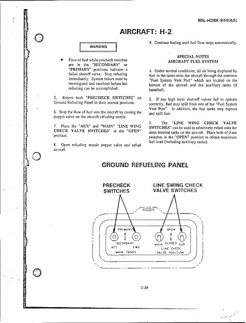
MIL-HDBK-844(AS)
AIRCRAFT: H-2
9. Continue fueling until fuel flow stops automatically.WARNING
SPECIAL NOTESFlow of fuel while precheck switches AIRCRAFT FUEL SYSTEMare in the "SECONDARY" or"PRIMARY" positions indicates a 1. Under normal conditions, all air being displaced byfailed shutoff valve. Stop refueling fuel in the tanks exits the aircraft through the commonimmediately. System failure must be "Fuel System Vent Port" which are lccated on theinvestigated and resolved before hot bottom of the aircraft and the auxiliary tanks (ifrefueling can be accomplished, installed).
5. Return both "PRECttECK SWITCHES" on 2. If any high level shut-off valves fail to operateGround Refueling Panel to their normal positions. correctly, fuel may spill from one of the "Fuel System
Vent Port". In addition, the fuel tanks may rupture6. Stop the flow of fuel into the aircraft by closing the and spill fuel.poppet valve on the aircraft refueling nozzle.
3. The "LINE WING CHECK VALVE7. Place the "AUrX" and "MAIN" "LINE WING SWITCHES" can be used to selectively refuel only theCtECK VALVE SWITClES" in the "OPEN" main internal tanks on the aircraft. Place both of theseposition. switches in the "OPEN" position to obtain maximum
fuel load (including auxiliary tanks).8. Open refueling nozzle poppet valve and refuelaircraft.
GROUND REFUELING PANEL
PRECHECK LINE SWING CHECKSWITCHES VALVE SWITCHES
( PRIMARA OPEN
I $ IISECONDA RY e CLOS;ED
AFT FWD LINE CHiEc-MAIN TANKS VALVE POSITION49
/0 - - - - -_ _-
C-39

MIL-HDBK-844(AS)
AIRCRAFT: H-2
PERSONNEL DANGER ZONES
8'-761 11 'A
C-40

MIL-HDBK-844(AS)
o AIRCRAFT: H-3AIRCRAFT CONFIGURATION
0
00
WZ Z
L>_
0LLJZ c
0)ULr U.C -1

MIL-HDBK-844(AS)
AIRCRAFT: H-3
TABLE OF FUEL CAPACITIES
Tank JaIon
Forward 341Internal Aft
Total 685
AIRCRAFT CHARACTERISTICS
Aircraft Dimensions f Aircraft Weight
Fuselage Maximum Gross WeightWidth 14 ft 20,000 lbs
Length 72 ft 8 in Maximum Footprint
Height 16 ft 102in 90 psi
H-3 REFUELING PROCEDURES
The following procedures cover only the refueling Again fuel flow should stop within 10 seconds.procedures which are unique to the H-3 aircraft,primarily the operation of the "pre-check" system. Inaddition to these specialized procedures, the applicable, CAUTIONbasic refueling procedures contained in chapter 6 or 12of the Aircraft Refueling NATOPS Manual, NAVAIR00-80T-109, must be followed. 0 If fuel flow does not stop in steps 3
or 5 above, doscontinue hot
1. Open Ground Refueling Panel access door. (VH-3 refueling operation immediately.
only) System failure must be investigatedand resolved before hot refueling can
2. Remove receptacle cap, attach refueling nozzle, be accomplished.
open nozzle to the fully open and locked position, andintiate fuel flow. 6. Release precheck switches and refuel aircraft untilfuel flow into the aircraft automatically stops indicating
3. Press and hold the switch on the Ground Refueling the aircrafts tanks are full.Panel labeled "PRI TEST". Fuel flow should stop SPECIAL NOTESwith in 10 seconds.SPCA NOE
AIRCRAFT FUEL SYSTEM4. Release the "PRI TEST" switch and resume fuelf4ow. 1. Under normal conditions, all air being displaced byfuel in the tanks exits the aircraft through the common
5. Repeat the precheck process in step four above, this "Fuel System Vent Port" which is located on the cabin
time pressing and holding the "SEC TEST" switch. skin in the approximate places indicated on the aircraftconfiguration diagram.
C-42

MIL-HDBK-844(AS)
AIRCRAFT: 1--3(1) 2. If any high level shut-off valves fail to operate 3. If externally mounted auxiliary tanks are installed,
correctly, fuel may spill from one of the "Fuel System they can only be refueled by gravity. It is notVent Port". In addition, the fuel tanks may rupturp recommended that these tanks be hot refueled.and spill fuel.
GROUND REFUELING PANEL
PRES RFULIMCPRE-CHEC'X
3 UN N 411tINC PI
.0O FUEL F MLO- T~
BUTTON~ S ACTuATf 0trol-r'e .0ICATES A AILEO MICH
Lff SUTOFF VAvfSTO3P R C UELIMC PRESSURE
ýO ~ ACT BURSTFUEL TANKS
(D PRI
TEST
Q~t 0(R .*" FAILEO rA($YST E, MCX FUEL 0 AM A-0
T T
S 28174 (B)
PRECHECK SWITCHES
C-43

MIL-HDBK-844(AS)
AIRCRAFT: H-3
PERSONNEL DANGER ZONES
915 (t)) o, -o F
-. , IRA_______
C-44
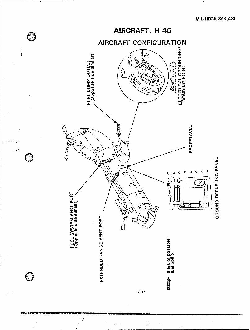
MIL-HDBK-84d4(AS)
AIRCRAFT: H-46
AIRCRAFT CONFIGURATION
u 0 I-
20Z~
CL-
LL w
0 w
wz
wwcr..
0z
o wM wr
00
zzw 0
>C-45
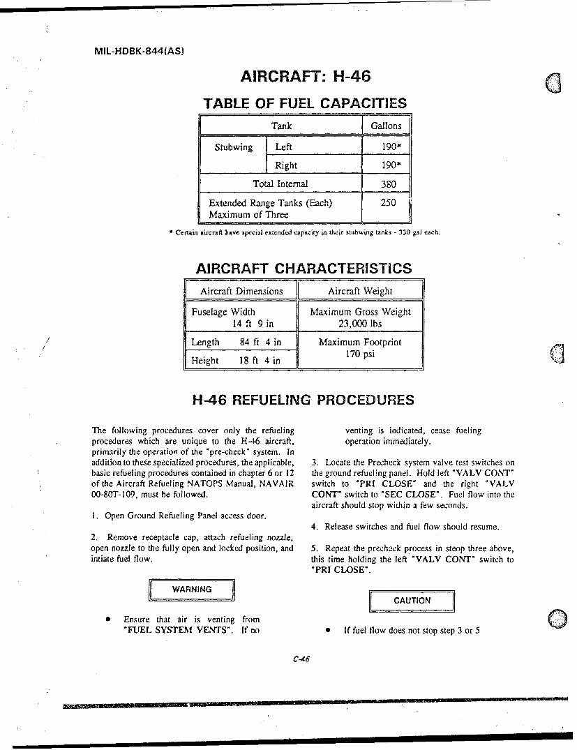
MIL-HDBK-844(AS)
AIRCRAFT: H-46
TABLE OF FUEL CAPACITIES
Tank Gallons
Stubwing Left 190*
Right 190*
Total Internal 380
Extended Range Tanks (Each) 250Maximum of Three
" Certain aircraft have special extended capacity in their stubwing tanks - 330 gal each.
AIRCRAFT CHARACTERISTICS
Aircraft Dimensions Aircraft Weight
Fuselage Width Maximum Gross Weight14 ft 9 in 23,000 lbs
Length 84 ft 4 in Maximum Footprint
Height 18 ft 4 in 170 psi
H-46 REFUELING PROCEDURES
The following procedures cover only the refueling venting is indicated, cease fuelingprocedures which are unique to the H-46 aircraft, operation immediately.primarily the operation of the "pre-check" system. Inaddition to these specialized procedures, the applicable, 3. Locate the Precheck system valve test switches onbasic refueling procedures contained in chapter 6 or 12 the ground refueling panel. Hold left "VALV CONT"of the Aircraft Refueling NATOPS Manual, NAVAIR switch to "PRI CLOSE" and the right "VALV00-80T-109, must be followed. CONT" switch to "SEC CLOSE". Fuel flow into the
aircraft should stop within a few seconds.1. Open Ground Refueling Panel access door.
4. Release switches and fuel flow should resume.2, Remove receptacle cap, attach refueling nozzle,open nozzle to the fully open and locked position, and 5. Repeat the precheck process in steop three above,intiate fuel flow, this time holding the left "VALV CONT" switch to
"PRI CLOSE*.l[WARNING
CAUTION
0 Ensure that air is venting from"FUEL SYSTEM VENTS". If no 0 If fuel flow does not stop step 3 or 5
C-46

MIL-HDBK-844(AS)
AIRCRAFT: H-46
above, discontinue hot refueling SPECIAL NOTESoperation immediately. System AIRCRAFT FUEL SYSTEMfailure must be investigated andresolved before hot refueling can be 1. Under normal conditions, all air being displaced byaccomplished, fuel in the tanks exits the aircraft through the common
"Fuel System Vent Port" which is located on each side6. Release switches and refuel aircraft until fuel flow of aircraft.into the aircraft stops and the fuel quantity gage on theground refueling panel indicates the tanks are full. 2. If any high level shut-off valves fail to operate
correctly, fuel may spill from one of the "Fuel SystemVent Port". In addition, the fuel tanks, which arelocated in the Stubwings, may rupture and spill fuel.
GROUND REFUELING PANEL
0
o CPRECHECK SWITCHES
0
0
0
COMPARTMENT FUEL QUANTITYLIGHT SWITCH INDICATOR
0C•47
- /E.UUJIU.u.LU ___________

MIL-HDBK-844(AS)
AIRCRAFT: H-46
PERSONNEL DANGER ZONES
220 :2 0 '8 6 0 0 v 2 ~ 6 ' 0 2
22
22 ZO 1 16 14 2 10 a 6 2 0 0 2A 6 a200 6ý 1 6 I 0 .
22 2 16 6 1 '2 0 8 ;o i so z'oo '4 20 '
V*
ENGINE EXHAUST WAKE PROFILE- FEET
200
C-48

MIL-HDBK-844(AS)
/0"N AIRCRAFT: H-53AIRCRAFT CONFIGURATION
0 0 wuz z -j
__ z
oz Ioz WI
-~- 0
00o 00 LUZ-LJC - -J C <0
(<0
0<ZZ
(<\IINL
0 '~ II
Li _ =
7' LL Li zV <
0C

MIL-HDBK-844(AS)
AIRCRAFT: H-53
TABLES OF FUEL CAPACITIES
MH-53E
Tank Gallons
No. 1 914.6Internal No. 2 1,383.2
No. 3 914.6
Total 3,212.4
CH-53E
Tank Gallons
No. 1 300
Internal No. 2 377
No. 3 300
Total 977
External Aux Tanks (Each) 650
Total With 2 Aux Tanks 2,277
CH-53A/D
Tank Gallons
Left 319Internal Right 319
Total 638
External Aux Tanks (Each) 650
Total With 2 Aux Tanks 1,938
C-50

MIL-HDBK-844(AS)
oAIRCRAFT: H-53
AIRCRAFT CHARACTERISTICS
CH-53E, MH-53E
Aircraft Dimensions Aircraft Weight
Fuselage Width 14 ft Maximum Gross Weight(With Aux Tanks) 73,500 lbs
Length 99 ft 0.5 in Maximum Footprint
Height 28 ft 0.5 in 135 si
CH-53A/D
Aircraft Dimensions Aircraft Weight
Fuselage Width 24 ft Maximum Gross Weight(With Aux Tanks) 42,000 lbs
Length 88 ft 6 in Maximum Footprint
Height 24 ft 11 in 135 psi
H-53 REFUELING PROCEDURES
The following procedures cover only the refueling this time turning the precheck valve labeled "SEC" toprocedures which are unique to the H-53 aircraft, the "CLOSED"position.primarily the operation of the "pre-check" system. Inaddition to these specialized procedures, the applicable,basic refueling procedures contained in chapter 6 or 12 WARNINGof the Aircraft Refueling NATOPS Manual, NAVAIR00-80T-I09, must be followed. 0 Flow of fuel while precheck valve(s)1. Open Ground Refueling Panel access door. are in closed position(s) indicates a
failed shutoff valve. Stop refueling
2. Remove receptacle cap, attach refueling nozzle, immediately. System failure must be
open nozzle to the fully open and locked position, and investigated and resolved before hot
intiate fuel flow. refueling can be accomplished.
3. Exercise the Precheck system. On A and D 4. Place precheck valves on Ground Refueling Panel
models, simultaneously turn both precheck valves on in the "OPEN" positions and refuel aircraft.
the Ground Refueling Panel to "CLOSED" positioa.Fuel flow into the aircraft should stop within 10 5. Monitor the "Tank Pressure Indicators" on theseconds. On the CH-53E and MH-53E, turn the Ground Reueing Panel.precheck valve labeled "PRI" to the "CLOSED"position and observe that fuel flow stops, then returnthe valve to the "OPEN" position. Repeat the last step
C.51

MiL-HDBK-844(AS)
AIRCRAFT: H-53
SPECIAL NOTESCAUTIONAIRCRAFT FUEL SYSTEM
0 Ifanytankpresureindcato ries1. Under normal conditions, all air being displaced byIf ay tak pessue inicaor rsesfuel in the tanks exits the aircraft through the commonabove 1,5 psi, stop refueling "Fuel System Vent Port" which is located on theimmdiaely BlckaeinVn bottom of the aircraft's fuselage.system must be investigated andcorrected prior to refueling. 2. If any high level shut-off valves fail to operate
correctly, fuel may spill from one of the "Fuel System7. Continue fueling until fuel flow stops automatically. Vent Port". In addition, the fu-el tanks may ruptureand spill fuel.
3. The A and D model aircraft can be fitted withinternal range extension tanks.. Special proceduresmust be followed by the aircrew in order to refuielthese taks.
GROUND REFUELING PANEL
~~------M tO E C O E
F , r 0X
1.LH. TANK R.H. TANK% 0 PRECHECK PRECHECK. 0 VALVE VALVE
GROUND REFUELING PANEL-CH-53E and MH-53E---------------.
GRUN REULN PAE
ALTENATEGROUND REFUELING PANELCC1+53AA/
C-52

MIL-P.DBK-844(AS)
0 AIRCRAFT: H-53PERSONNEL DANGER ZONES
I ..... ?.e, , ' . ý2-
z?
0jD s SIC31C -SI

MIL-HDBK..844(AS)
AIRCRAFT: SH-60AIRCRAFT CONFIGURATION
zz
nw
0 z/ 0 00o
<0 a.z
-JIM
0 <
uJ~~ 0-
wuC-54

MlL-HDBK-844(AS)
o AIRCRAFT: SH-60
TABLE OF FUEL CAPACITIES
[.Tank Gallons
Main 590
Left 120External Aux Right 120
Internal Aux (SH-60F only) 105
Total Main + Aux 830
Total SH-60 935
AIRCRAFT CHARACTERISTICS
Aircraft Dimensions Aircraft Weight
Fuselage Width Maximum Gross Weight7 ft 9 in 22,000 lbs
(With Aux Tanks)
C:) Length 64 ft 10 in Maximum Footprint
SHeight 17 ft 90 psi
SH-60 REFUELING PROCEDURES
The following procedures cover only the refuelingprocedures which are unique to the SH-60 aircraft, CAUTIONprimarily the operation of the "pre-check" system. in I
addition to these specialized procedures, the applicable,basic refueling procedures contained in chapter 6 or 12 0 If tank pressure indicator enters theof the Aircraft Refueling NATOPS Manual, NAVAIR red band, stop refueling00-80T-109, must be followed, immediately. Blockage in vent
system must be investigated andI. Open Ground Refueling Panel access door. corrected prior to refueling.
2. Remove receptacle cap, attach refueling nozzle, 4 Hold the "OUTBOARD PRECHECK VALVE" in
open nozzle to the fully open and locked position, and the "PRECHECK" position. Fuel flow should stopintiate fuel flow. within 6 seconds.
3. Monitor the "Tank Pressure inidicator" on the 5. Release the "OUTBOARD PRECHECK VALVE"Ground Refueling Panel. and resume fuel flow.
0 6. Repeat the precheck process in step four above, thistime holding the "INBOARD PRECHECK VALVE"
C-55
-- 1
I.. , . . . . .-1. .. " :

/
MIL-HDBK-844(AS)
AIRCRAFT: SH-60in the "PRECITECK" position. Again fuel flow SPECIAL NOTESshould stop within 6 seconds. AIRCRAFT FUEL SYSTEM
1. Under normal conditions, all air being displaced byCAUTIONfuel in the tanks exits the aircraft through the common
"Fuel System Vent Port" which is located on thef bottom of the aircraft's fuselage. The SH-60F aircraft
S I fuello disontnes not stpsepf4eorn6 has ani internal auxiliary tank which vents to anabove, discontinue hot refueling opening on the lower port side of the aircraft near theoperation immediately. System front. Each external auxiliary tank has a vent openingfailure must be investigated and on its bottom approximately in the center.
.. resolved before hot refueling can be
accomplished. 2. If any high level shut-off valves fail to operate
correctly, the tanks may rupture and/or fuel may spillS6. Release precheck valves and refuel aircraft until from one of the Fuel System Vent Port".
fuel flow into the aircraft automatically stops indicating
the aircraft's tanks are full. 3. The SH-60F aircraft has a second Tank Pressure
Indicator which displays the pressure in the InternalAuxiliary Tank.
GROUND REFUELING PANELOUTBOARD TANK PRESSUREPRECHECK INDICATOR •:
INBOARD RCPALPRECHECKVALVE
0" 0
C-56
0' 00.
0 -0- ._ .. ... ."
I~ 0 '1 II I I

MIL-HDBK-844(AS)
Q AIRCRAFT: SH-60
PERSONNEL DANGER ZONES
TV - _t I 1111I i i ___ j27' OUT TO 17'7 FT "I, l l I I
i -
0 OTTSf T
t t50' OUT T- O 62 FT! '. T 1 tI 1 1 I UT," 1 FT
___,__ __ I,. ! /• ! °°°' .
OU TO 10 f 20 OU TO 10 ,FT/i "
-//I,
'a30 FT/ SEC -
. /5 o 3 5 3 0 4 50 .;1o • .oo5 5 10 i 2 5 i l ls ; : E5 so $S
EXHAUST WAKE VELOCITY FT/SEC EXHAUST WAKE TENP C
45 i' 35 10 Z5 20 15 10 5 0 0 S 10 is 20 2S 30 3S AO 45 50 S,
4... p..'' . j I ___ __ ___TO 117 FFI2 U
150 o 1,0so .jT
C-57
.. . ':'- " , - _.IC . , .... .. .. ,

MIL-HDBK..84(AS)
(This page intentionally left blank).Q
C-58

MIL-HDBK-844(AS)
Q APPENDIX D
GLOSSARY
AFFF ContaminantsThe acronym for Aqueous Film forming Substances either foreign or native whichFoam, the department of Defense standard may be present in fuel that detract from itsfirefighting agent for flammable and performance.combustible liquid fires.
CowlingAdsorption Removable covering around engine
A separation method where one sections.component is concentrated on the surfaceof a porous solid. Surfactants (surface Cyclone Separatoractive agents) are separated from jet fuel A device that used the principal ofby adsorption on clay. centrifugal force to cause the contaminate
in a fuel to settle to the bottom of theAmbient Temperature vessel without the use of filter media.
The air temperature surrounding a specificarea. Density
The amount of mass (weight) in a unitAPI Gravity volume of a material.
The petroleum industry's scale and methodof measuring density of petroleum Differential Pressure (Delta P)products. The measured difference in pressure
between any two points, generally at theAviation Gasoline (avgas) inlet and outlet of a filter or a
Specially blended gasolines used to power filter/separator.reciprocating piston aircraft engines.
Disarming ActionClay Treater As applied to, filter/separators, the
A treating unit that utilizes a special clay rendering of the elements incapable of(Fuller's earth) to remove surfactants from performing their designed functions; e.g.,turbine fuel. coalescer elements incapable of coalescing
w2ter and separator elements incapable ofCMC separating water from fuel.
Commandant of the Marine Corps.Dissolved Water
CNATRA Water which is in solution in the fuel. ThisCnief of Naval Air Training. water is not free water and cannot be
removed by conventional means.CNO
Chief of Naval Operations. Eductor1. A device placed in a hose line to
Coalescence proportion liquid foam or wetting agentsThe oroperty of a filter cartridge to bring into the fire stream.together very fine droplets of free andentrained water to form large droplets 2. An ejector that siphons water bywhich are heavy enough to fall to the creating a vaccum from the velocity ofbottom of the filter/separator vessel, water passing through it.
0D-1

M!L-HDBK-844(AS)
Effluent FlapsStream of fluid at the outlet of a filter or A movable airfoil attached to the trailingfilter/separatot. This is the opposite cf edge of the wing which improves theinfluent. aerodynamic performance of the aircraft
during takeoffs and landings.Empennage
Aircraft tail assembly including stabilizers, Flash Pointelevators, rudders, etc. The lowest fuel temperature at which the
vapor above the fuel will ionite.Emulsion
A dispersion of two dissimilar immiscible Floating Suctiondroplets in the continuous phase. A floating device used in a tank for
drawing product from the upper level of theEntrained Water fuel.
Small droolets of free water in suspensionwhich may make fuel appear hazy. FMFPAC/LANT
Fleet Marine Force, Pacific or Atlantic.E0D
Explosive ordnance disposal. Free WaterWater in th,, fuel other than dissolved
ETA water. Free water mazy be in the form ofEstimated time of arrival, droplets or haze suspended in the fue'
(entrained water) and/or a water layer atExhaust the bottom of the container holding the
The part of tiie engine through which the fuel. Free water may also exist in the formexhaust gases are ejected. of an emulsion which may be so finely
dispersed as to be invisible to the nakedFilter eye.
A device to remove solid contaminantsfrom fuel. Freezing Point (Fuel)
Tne lowest fuel temperature Et which thereFilter Membrane (Millipore) Test are no crystals.
A standard test in which fuel is passedthrough a small filter membrane housed in Halogenated agenta plastic holder. The cleanliness of the fuel An extinguishing agent composed ofcan be determined by examining the hydrocarbons in which one or morerjmbrane. hydrogen atoms have been replaced by
halogen atoms; the common halogenFilter/Separator elements used are fluorine, chlorine,
A mechanical device used to remove bromine, and iodine.entrained particulate contaminants and freewater from a fuel. Hazardous material
Any substance which, by reason of beingFin explosive, flammable, poisonous, corrosive,
A fixed or adjustable airioil ior directional oxidizing, irritating, or otherwise harmful, isstability, such as a tail fin cr a skid fin. A likely to cause death or injury.common name given the vertical stabilizer.
Landing gearFixed Base Operator (FBO) The understructure which supports the
Common title for aviation fuel dealer at the weight of an aircraft when in contract withairport. land. It usually contains a mechanism for
reducing the shock of landing (also called
undercarriage).
D-2

MIL-HDBK-844(AS)
. Hydrophilic NFPAWater accepting or water wettable. National Fire Protection Association.
Immiscible OPNAVINSTLiquids which are mutually insoluble. This Chief of Naval Operations Instruction.is the opposite of miscible.
OxidizerInfluent 1. A substance that readily gives up
Stream of fluid at the inlet of a filter or oxygen without requiring an equivalent offilter/separator. This is the opposite of another element in return.effluent.
Longerons 2. A substance that contains an atom orThe principal longitudinal structural atomic group that gains electrons, such asmembers of the fuselage. oxygen, ozone, chlorine, hydrogen
peroxide, nitric acid, metal oxides,Micron (micrometer) chloratas,, and permanganates (also called
A unit of linear measurement. One micron oxidizing agent).is equal to .000029 in. and approximately25,400 microns equals 1 in. For example, Particulate Matterthe average human hair is about 100 Solid contaminants (e.g., dirt, rust, scale,microns in diameter. sand, etc.) sometimes found in fuel.
Miscible PodLiquids which are mutually soluble. This is The enclosed streamlined housing around
O the opposite of immiscible, the jet engine.
Monitor PrefilterA device which shows or gives warning of A filter which has a high dirt-holdingimproper performance (noun); or to test or capacity which is installed up-stream ofcheck performance on a continuing basis other filtraticn equipment.(verb).
Pressure DropNacelle See Differential Pressure above.The enclosed streamlined housing for a
powerplant. A nacelle is usually shorter Pylon, nacelle strutthan a fuselage and does not car;y the tail The' structure that attaches a jet engine tounit. the wing.
NATSF Relative Density (Specific Gravity)Naval Air Technical Services Facility. In fuel, this is the ratio of weight of any
volume of fuel to the weight of an equalNAVAIR volume of water.
Naval Air Systems Command.Rudder
NAVFAC The upright movable part of the tailNaval Facilities Engineering Command. assembly which controls the direction(yaw)
of the aircraft.NAVSEA
Naval Sea Systems Command. Settling TimeThe time allowed for water or dirt entrained
NAVSUP in the fuel to drop to the bottom of theNaval Supply Systems Command. storage tank.
D-3
MIL-HDBK-844(AS)
SlatA movable auxiliary airfoil, the primaryfunction of which is to increase thestability of the aircraft. Slats are found onthe leading edge of the wing.
Specific GravitySee Relative Density above.
StabilizerAny airfoil the primary function of which isto increase the stability of the aircraft. Theterm stabilizer is most commonly used inreference to the fixed horizontical tailsurface of the aircraft.
SumpA low point in a system for collection andremoval of water and solid contaminants.
SurfactantAny wetting agent.
Surfactants (Surface Active Agents)Chemical substances which make itdifficult to separate fuel and water and thatdisarm filter/separators.
T. A.U.
Twin agent fire extinguisher
T.O.Technical order.
Thief (Sump) PumpA small pump having a suction line whichextends to the low point of a tank for thepurpose of drawing off water which mayhave accumulated.
Turbine FuelA group of various kerosines or wide-cuttypes of fuels used to power aircraftturbine engines.
Water SlugA large amount of free water.
D-4

MIL-HDBK-844(AS)
INDEX
B N
bonding . ................ 6-5, 6-6, 6-7 nozzle ....... 4-1, 6-6, 6-8, 6-9, 6-10, C-4
C P
CCFD .. ..................... 5-1, 5-3 particulate ................ 4-1, 4-2, 4-5,CFD .................... 5-1, 5-2, 5-3 5-1, 5-2, 6-16, 0-2, D-3clothing .. ...................... 6-13 PKP ....................... 6-8, 6-10
D R
Jefueling ........ 6-1, 6-4, 6-5, 6-7, 6-13 relaxation chambers . ........... 3-2, 6-6deterioration use limits ......... 3-4, 4-2
SE
sampling .......... 2-2, 4-5, 5-2, 5-3, 5-4earthing .. ....................... 6-7 spill . .................. 2-1, 6-10, C-4extinguishment .......... 6-7, 6-8, 6-10 static electricity ................... 6-4
F T
filter/separator ....... 4-3, 4-4, 6-5, 6-13, tank car .. ....................... 2-2D-1, D-2, D-3 tank truck ....................... 2-2
flame spread rate . ............. 6-2, 6-3 testing .......... 1-1, 3-4, 4-3, 4-5, 5-2,fsii . 3-2, 3-3, 4-2, 4-3, 4-4, 5-1, 5-4, 6-13 5-4, 6-2, B-1, B-2fuel system icing inhibitor ....... 3-2, 4-2, testing equipment
5-1, 5-4, 6-13 contaminated fuel detector (CFD) . . . 5-1FWD ........................ 5-1, 5-3 conductivity meter .......... 3-4, 5-4
free water detector ............. 5-3G fuel system icing inhibitor (FSII) test kit 5-4
truck . .................. 2-2, 4-3, 4-4grounding . ............... 5-2, 5-3, 6-7
V
Hvapor pressure ......... 4-5, 6-1, 6-2, 6-9
halon ..................... 6-8, 6-9health hazards .............. 6-10, 6-13 Whoses ........................... 4-2hot refueling .................. 2-1, C-4 water ....... . 2-2, 3-1, 3-2, 3-3, 3-4, 3-5,hydrant ... ....................... 4-4 4-1, 4-2, 4-3, 4-4, 4-5, 5-1, 5-3, 5-4,
6-5, 6-6, 6-8, 6-10, 6-13, 6-16,6-17, D-1, D-2, D-3, D-4
ignition .......... . 6-1, 6-4, 6-5, 6-7, 6-8
M
meter ........... 3-4, 4-1, 5-1, 5-2, 5-4
Index- I

MIL-HDBK-8441AS)
CONCLUDING MATERIALCustodian:
Navy - AS Preparing activity:Navy - AS
(Project 9130-NO01 )
* I:

Q STANDARDIZATION DOCUMENT IMPROVEMENT PROPOSAL
INSTRUCTIONS
1. The preparing activity must complete blocks 1, 2, 3, and 8. In block 1, both the document number and revisionletter should be given.
2. The submitter of this form must complete blocks 4, 5, 6, and 7.
3. The preparing activity must provide a reply within 30 days from receipt of the form.
NOTE: This form may not be used to request copies of documents, nor to request waivers, or clarification ofrequirements on current contracts. Comments submitted on this form do not constitute or imply authorization towaive any portion of the referenced document(s) or to amend contractual requirements.
I RECOMMEND A CHANGE: 1. ODCUMENT NUMbR 2. OOC6MEIof"ATE %YYMMDO)N51-1-fDBK-844'(AS) 20 October 19 2.
". 0o lkWi.rREFUELING HIANDBOOK
4. NAUR1 Of C'iAAGE (Ajenoty paragr'apJ, number and onclude proposed rewni., it pot/e. Artach e.•ra sheeut as rieded)
S. REASON FOR RECOMMENOATION
&. suBMiTTERa. NAME (a.i•t, k mkAdie hi'/, b. ORGANIZAT)ON
,. ADO1.K$$ ((ncfude Zip Code) d. TIELEPHONE "rKJude Ajea Code) 7. DATE SUUMhITED(VVMMODJ(1) C-6111c~
8. PREPARING AC'7VITY
a NAME b TELEPHONE (Incilude Area Code)(1) Commetoal (2) AUTOVON
Naval Air Systems Command AIR-5363C 202-692-2653 222-2653
Rdaa, IF YOU 0O NOr RECEI A REPLY WITHIN 4S DAYS, CONTACT:Defense Quality and Standardization Office
AIR-5363C S203 teesburg Pike. Suite 1403. Falils Church. VA 22041.3466
Washington, DC 20361-5360 Telephone (703)756.2340 AUTOVON 289.2340
DO Form 1426. OCT 89 Pie.,oui edtonu ,re obsolete.