072-090 Models 180-240 Models - Surplus Group€¦ · program, which is based on AHRI Standard...
20
AIR CONDITIONERS TS T-CLASS™ SPLIT SYSTEM UNITS R-410A - 60 HZ Bulletin No. 210524 June 2011 Supersedes January 2011 EER up to 11.7 6 to 20 Tons Cooling Capacity - 71,000 to 236,000 Btuh MODEL NUMBER IDENTIFICATION T S A 120 S 4 S N 1 Y Major Design Sequence A = 1st Generation B = 2nd Generation Unit Type S = Split System Air Conditioner Brand/Family T = T-Class™ Product Line Cooling Efficiency S = Standard Efficiency Minor Design Sequence 1 = 1st Revision 2 = 2nd Revision 3 = 3rd Revision Voltage Y = 208/230V-3 phase-60hz G = 460V-3 phase-60hz J = 575V-3 phase-60hz Nominal Cooling Capacity − Tons 072 = 6 Tons 090 = 7.5 Tons 120 = 10 Tons 150 = 12.5 Tons 180 = 15 Tons 240 = 20 Tons Refrigerant Type 4 = R−410A Refrigerant Circuits S = Single Circuit D = Dual Circuits Part Load Capability N = Single Stage Compressor 072-090 Models 120-150 Models 180-240 Models PRODUCT SPECIFICATIONS
Transcript of 072-090 Models 180-240 Models - Surplus Group€¦ · program, which is based on AHRI Standard...

A I R C O N D I T I O N E R S
TST-CLASS™ SPLIT SYSTEM UNITS
R-410A - 60 HZ Bulletin No. 210524
June 2011Supersedes January 2011
EER up to 11.76 to 20 Tons
Cooling Capacity - 71,000 to 236,000 Btuh
MODEL NUMBER IDENTIFICATION
T S A 120 S 4 S N 1 Y
Major Design SequenceA = 1st Generation
B = 2nd Generation
Unit TypeS = Split System Air Conditioner
Brand/FamilyT = T-Class™ Product Line
Cooling EfficiencyS = Standard Efficiency
Minor Design Sequence1 = 1st Revision 2 = 2nd Revision 3 = 3rd Revision
VoltageY = 208/230V-3 phase-60hzG = 460V-3 phase-60hzJ = 575V-3 phase-60hz
Nominal Cooling Capacity − Tons072 = 6 Tons
090 = 7.5 Tons 120 = 10 Tons
150 = 12.5 Tons 180 = 15 Tons 240 = 20 Tons
Refrigerant Type4 = R−410A
Refrigerant CircuitsS = Single Circuit D = Dual Circuits
Part Load CapabilityN = Single Stage Compressor
072-090 Models
120-150 Models
180-240 Models
P R O D U C T S P E C I F I C AT I O N S
TS 6 to 20 Ton R−410A Air Conditioners / Page 2
EQUIPMENT Warranty
Compressor - limited warranty for five years in non-residential applications.All other covered components - one year in non-residential applications.Refer to Lennox Equipment Limited Warranty certificate for specific details.
APPLICATIONS
Air conditioners are available in 6, 7.5, 10 ton (one compressor) and 10, 12.5, 15 and 20 ton (two compressors) nominal sizes.Matching air handlers provide a wide range of cooling capacities and applications. See AHRI Ratings tables.See Air Handlers sections for data.Units shipped completely factory assembled, piped, and wired. Each unit is test operated at the factory insuring proper operation.Installer must set air conditioner, connect refrigerant lines, add refrigerant charge and make electrical connections to complete job.
APPROVALS
All units tested in Lennox’ Research Laboratory environmental test room or ETL certified environmental testing facility.Certified in accordance with the ULE certification program, which is based on AHRI Standard 340/360-2007.Sound tested in Lennox reverberant sound test room in accordance with test conditions included in AHRI Standard 270-95 or 370-2001.Units and components within are bonded for grounding to meet safety standards for servicing required by UL, ULC, NEC and CEC.All units are ETL listed.ISO 9001 Registered Manufacturing Quality System.
A
Contents
AHRI System Matches..................................................8Dimensions .................................................................10Features And Benefits ..................................................2Guide Specifications ...................................................13Model Number Identification .........................................1Optional Conventional Temperature Control Systems ..5Options / Accessories ..................................................7Sound Data ..................................................................4Specifications................................................................6Unit Clearances ............................................................9Weight Data .................................................................8
FEATURES AND BENEFITS
072-090 Models
120-150 Models
180-240 Models
B
C
D
E
F
G
H
I
J
K

TS 6 to 20 Ton R−410A Air Conditioners / Page 3
REFRIGERATION SYSTEM
RefrigerantUnits operate with chlorine-free, ozone friendly, R-410A (field furnished).Outdoor Coil Fan(s)TSA072 and TSA090 units have one outdoor fan. TSA120 and TSA150 units have two outdoor fans. TSA180 and TSA240 units have four outdoor fans.Direct drive fan(s) moves large volumes of air uniformly through entire condenser coil(s) for high refrigerant cooling capacity.Upward discharge of air reduces operating sound levels and prevents damage to lawns, shrubs, and walkways.Fan motors are totally enclosed, overload protected and equipped with a rain shield.Fan service access is accomplished by removal of fan guard(s) or removal of access panel.Copper Tube/Enhanced Fin Coil(s)Units are equipped with a wrap-around “U” shaped coil (072-090-120 models) or two “L” shaped coils (150-180-240 models).Lennox designed and fabricated coils constructed of precisely spaced ripple-edge aluminum fins machine fitted to seamless copper tubes.Lanced fins provide maximum exposure of fin surface to air stream resulting in excellent heat transfer.Fins equipped with collars that grip tubing for maximum contact area.Flared shoulder tubing connections and machine brazed silver soldering provide tight, leakproof joints.Long life copper tubing is corrosion-resistant and easy to field service.Thoroughly factory tested under high pressure to ensure leakproof construction.Completely accessible for cleaning.High Pressure SwitchShuts off unit if abnormal operating conditions cause discharge pressure to rise above setting.Protects the compressor from excessive condensing pressure.Manual reset.Loss of Charge SwitchShuts off unit if liquid line pressure falls below setting.Provides loss of charge and freeze-up protection.Automatic reset.Hi-Capacity Drier(s)Drier traps moisture or dirt that could contaminate the refrigerant system.
B
C
D
E
F
FEATURES AND BENEFITS
Refrigerant Lines and Service ValvesSuction and liquid lines are located on corner of unit cabinet and are made with sweat connections. See dimension drawings.Fully serviceable suction and liquid line service valves provide complete service access to refrigerant system.Suction valve can be fully shut off, while liquid valve can be front seated to manage refrigerant charge while servicing system. Accessible outside of unit cabinet.
COMPRESSORS
TSA072, TSA090 and TSA120S4S models feature a single scroll compressor. TSA120S4D, TSA150, TSA180 and TSA240 models have two scroll compressors.Compressor features high efficiency with uniform suction flow, constant discharge flow and high volumetric efficiency and quiet operation.Compressor consists of two involute spiral scrolls matched together to generate a series of crescent shaped gas pockets between them.During compression, one scroll remains stationary while the other scroll orbits around it.Gas is drawn into the outer pocket, the pocket is sealed as the scroll rotates.As the spiral movement continues, gas pockets are pushed to the center of the scrolls. Volume between the pockets is simultaneously reduced.When pocket reaches the center, gas is now high pressure and is forced out of a port located in the center of the fixed scrolls.During compression, several pockets are compressed simultaneously resulting in a smooth continuous compression cycle.Continuous flank contact, maintained by centrifugal force, minimizes gas leakage and maximizes efficiency.Scroll compressor is tolerant to the effects of slugging and contaminants. If this occurs, scrolls separate, allowing liquid or contaminants to be worked toward the center and discharged.Low gas pulses during compression reduces operational sound levels.Compressor motor is internally protected from excessive current and temperature.Compressor is installed in the unit on resilient rubber mounts for vibration free operation.Crankcase Heater(s) (All Models)Crankcase heater(s) prevents migration of liquid refrigerant into compressor(s) and ensures proper compressor lubrication.
G
H

TS 6 to 20 Ton R−410A Air Conditioners / Page 4
FEATURES AND BENEFITS
CABINET
Heavy-gauge, pre-painted steel cabinet provides superior rust and corrosion protection.Removable panels allow access for unit servicing.Heavy duty steel base channels raise the unit off of mounting surface away from damaging moisture.Unit lifting holes and forklift slots furnished in base rails.See dimension drawings.Control BoxControl box located in separate compartment in unit cabinet .All controls are pre-wired at the factory.Control box is large enough for field installed DDC or other field supplied control modules.
OPTIONS
Factory InstalledCorrosion ProtectionPolymeric epoxy coating that is deposited by electrical transport (electrophoresis), using a process known as electrocoat (e-coat). Available for enhanced coil corrosion protection. Factory installed on the condenser coil. Painted base pan is provided with this option.Field InstalledCoil GuardsHeavy duty sheet metal and metal mesh enclosures protect coils from damage. Field installed.Hail GuardsHeavy duty sheet metal and metal mesh enclosures protect coils from damage. Field installed.
I
J
K
CONTROLS
OPTIONS
Field InstalledL Connection® NetworkComplete building automation control system for single or multi-zone applications. Options include local interface, software for local or remote communication, and hardware for networking other control functions.See L Connection Network Product Specifications Bulletin for details.Network Thermostat ControllerRequired for use with the L Connection Network. Monitors and controls system operation.Low Ambient ControlAir conditioning units operate satisfactorily down to 30ºF outdoor air temperature without any additional controls.Low Ambient Control Kit can be field installed, allowing unit operation down to 0ºF.ThermostatThermostat is not furnished with unit and must be ordered extra.See 5, individual Thermostat bulletins and Lennox Price Book.
SOUND DATA 1 Unit
Model No.Octave Band Linear Sound Power Levels dB, re 10-12 Watts Center Frequency - HZ 1 Sound Rating
Number (dB)63 125 250 500 1000 2000 4000 8000TSA072S4S 60 65 68 73 76 72 68 63 81TSA090S4S 56 64 69 73 77 74 70 63 81TSA120S4S 61 70 77 82 81 77 75 71 86TSA120S4D 65 71 77 80 80 77 72 67 85TSA150S4D 62 68 77 80 82 78 73 65 86TSA180S4D 66 73 80 83 83 79 74 66 88TSA240S4D 66 73 80 85 84 80 78 74 89
NOTE - the octave sound power data does not include tonal correction. 1 Tested according to AHRI Standard 270-2008 test conditions.
TS 6 to 20 Ton R−410A Air Conditioners / Page 5
OPTIONAL CONVENTIONAL TEMPERATURE CONTROL SYSTEMS - FIELD INSTALLED
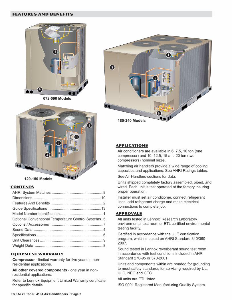
COMMERCIAL TOUCHSCREEN THERMOSTATIntuitive Touchscreen Interface - Two Stage Heating / Two Stage Cooling Conventional or Heat Pump - Seven Day Programmable - Four Time Periods/Day - Economizer Output - Title 24 Compliant - ENERGY STAR® Qualified - Backlit Display - Automatic Changeover
C0STAT02AE1L(14W81)
Sensors For Touchscreen Thermostat1 Remote non-adjustable wall mount 20k temperature sensor ......................... C0SNZN01AE2-
(47W36)1 Remote non-adjustable wall mount 10k averaging temperature sensor ........ C0SNZN73AE1-
(47W37)1 Remote non-adjustable duct mount temperature sensor ............................... C0SNDC00AE1-
(19L22)Outdoor temperature sensor ............................................................................ C0SNSR03AE1-
(X4148)Accessories For Touchscreen Thermostat
Locking cover (clear) ........................................................................................ C0MISC15AE1-(39P21)
1 Remote sensors for C0STAT02AE1L can be applied in the following combinations: (1) C0SNZN01AE1-, (2) C0SNZN73AE1-, (2) C0SNZN01AE1- and (1) C0SNZN73AE1-, (4) C0SNZN01AE1-, (3) C0SNZN01AE1- and (2) C0SNZN73AE1.
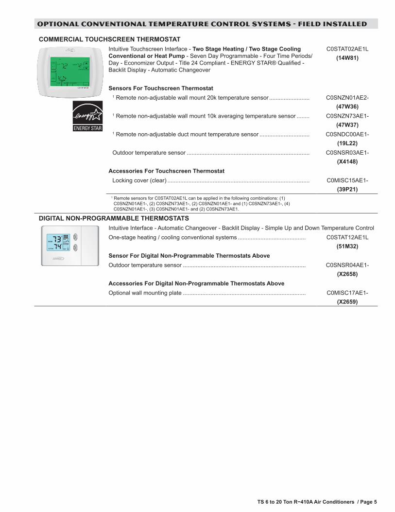
DIGITAL NON-PROGRAMMABLE THERMOSTATSIntuitive Interface - Automatic Changeover - Backlit Display - Simple Up and Down Temperature ControlOne-stage heating / cooling conventional systems .......................................... C0STAT12AE1L
(51M32)Sensor For Digital Non-Programmable Thermostats AboveOutdoor temperature sensor ............................................................................ C0SNSR04AE1-
(X2658)Accessories For Digital Non-Programmable Thermostats AboveOptional wall mounting plate ............................................................................ C0MISC17AE1-
(X2659)
TS 6 to 20 Ton R−410A Air Conditioners / Page 6
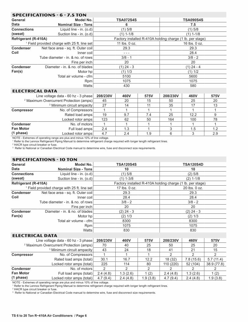
SPECIFICATIONS - 6 - 7.5 TONGeneral Data
Model No. TSA072S4S TSA090S4SNominal Size - Tons 6 7.5
Connections (sweat)
Liquid line - in. (o.d) (1) 5/8 (1) 5/8Suction line - in. (o.d) (1) 1-1/8 (1) 1-1/8
Refrigerant (R-410A) Factory installed R-410A holding charge (1 lb. per stage)1 Field provided charge with 25 ft. line set 11 lbs. 0 oz. 16 lbs. 0 oz.
Condenser Coil
Net face area - sq. ft. Outer coil 29.3 29.3Inner coil - - - 28.4
Tube diameter - in. & no. of rows 3/8 - 1 3/8 - 2Fins per inch 20 20
Condenser Fan(s)
Diameter - in. & no. of blades (1) 24 - 3 (1) 24 - 4Motor hp (1) 1/3 (1) 1/2
Total air volume - cfm 5100 5600Rpm 1075 1075
Watts 430 580ELECTRICAL DATA
Line voltage data - 60 hz - 3 phase 208/230V 460V 575V 208/230V 460V 575V2 Maximum Overcurrent Protection (amps) 45 20 15 50 25 20
3 Minimum circuit ampacity 27 14 11 35 17 13Compressor No. of Compressors 1 1 1 1 1 1
Rated load amps 19 9.7 7.4 25 12.2 9Locked rotor amps 123 62 50 164 100 78
Condenser Fan Motor (1 phase)
No. of motors 1 1 1 1 1 1Full load amps 2.4 1.3 1 3 1.5 1.2
Locked rotor amps 4.7 2.4 1.9 6 3 2.9NOTE - Extremes of operating range are plus and minus 10% of line voltage. 1 Refer to the Lennox Refrigerant Piping Manual to determine refrigerant charge required with longer length refrigerant lines. 2 HACR type circuit breaker or fuse. 3 Refer to National or Canadian Electrical Code manual to determine wire, fuse and disconnect size requirements.
SPECIFICATIONS - 10 TONGeneral Data
Model No. TSA120S4S TSA120S4DNominal Size - Tons 10 10
Connections (sweat)
Liquid line - in. (o.d) (1) 5/8 (2) 5/8Suction line - in. (o.d) (1) 1-3/8 (2) 1-1/8
Refrigerant (R-410A) Factory installed R-410A holding charge (1 lb. per stage)1 Field provided charge with 25 ft. line set 17 lbs. 0 oz. 20 lbs. 0 oz.
Condenser Coil
Net face area - sq. ft. Outer coil 29.3 29.3Inner coil 28.4 28.4
Tube diameter - in. & no. of rows 3/8 - 2 3/8 - 2Fins per inch 20 20
Condenser Fan(s)
Diameter - in. & no. of blades (2) 24 - 3 (2) 24 - 3Motor hp (2) 1/3 (2) 1/3
Total air volume - cfm 8300 8300Rpm 1075 1075
Watts 830 830ELECTRICAL DATA
Line voltage data - 60 hz - 3 phase 208/230V 460V 575V 208/230V 460V 575V2 Maximum Overcurrent Protection (amps) 70 40 25 50 25 20
3 Minimum circuit ampacity 43 24 18 41 21 15Compressor No. of Compressors 1 1 1 2 2 2
Rated load amps (total) 30.1 16.7 12.2 18 (32) 7.8 (15.6) 5.7 (11.4)Locked rotor amps (total) 225 114 80 110 (220) 52 (104) 38.9 (77.8)
Condenser Fan Motor (1 phase)
No. of motors 2 2 2 2 2 2Full load amps (total) 2.4 (4.8) 1.3 (2.6) 1 (2) 2.4 (4.8) 1.3 (2.6) 1 (2)
Locked rotor amps (total) 4.7 (9.4) 2.4 (4.8) 1.9 (3.8) 4.7 (9.4) 2.4 (4.8) 1.9 (3.8)NOTE - Extremes of operating range are plus and minus 10% of line voltage. 1 Refer to the Lennox Refrigerant Piping Manual to determine refrigerant charge required with longer length refrigerant lines. 2 HACR type circuit breaker or fuse. 3 Refer to National or Canadian Electrical Code manual to determine wire, fuse and disconnect size requirements.

TS 6 to 20 Ton R−410A Air Conditioners / Page 7
SPECIFICATIONS - 12.5 - 20 TONGeneral Data
Model No. TSA150S4D TSA180S4D TSA240S4DNominal Size - Tons 12.5 15 20
Connections (sweat)
Liquid line - in. (o.d) (2) 5/8 (2) 5/8 (2) 5/8Suction line - in. (o.d) (2) 1-1/8 (2) 1-1/8 (2) 1-3/8
Refrigerant (R-410A) Factory installed R-410A holding charge (1 lb. per stage)1 Field provided charge with 25 ft. line set 21 lbs. 0 oz. 29 lbs. 0 oz. 35 lbs. 0 oz.
Condenser Coil
Net face area - sq. ft. Outer coil 34.2 58.7 58.7Inner coil 33.3 57.7 57.7
Tube diameter - in. & no. of rows 3/8 - 2 3/8 - 2 3/8 - 2Fins per inch 20 20 20
Condenser Fan(s)
Diameter - in. & no. of blades (2) 24 - 4 (4) 24 - 3 (4) 24 - 3Motor hp (2) 1/2 (4) 1/3 (4) 1/3
Total air volume - cfm 10,300 16,600 16,600Rpm 1075 1075 1075
Watts 1130 1660 1660ELECTRICAL DATA
Line voltage data - 60 hz - 3 phase 208/230V 460V 575V 208/230V 460V 575V 208/230V 460V 575V2 Maximum Overcurrent Protection (amps) 60 30 25 90 40 30 100 50 40
3 Minimum circuit ampacity 49 25 20 66 33 25 78 43 32Compressor No. of Compressors 2 2 2 2 2 2 2 2 2
Rated load amps (total)
19 (38)
9.7 (19.4)
7.4 (14.8)
25 (50)
12.2 (24.4)
9 (18)
30.1 60.2)
16.7 (33.4)
12.2 (24.8)
Locked rotor amps (total)
123 (246)
62 (124)
50 (100)
164 (328)
100 (200)
78 (156)
225 (450)
114 (228)
80 (160)
Condenser Fan Motor (1 phase)
No. of motors 2 2 2 4 4 4 4 4 4Full load amps
(total)3
(6)1.5 (3)
1.2 (2.4)
2.4 (9.6)
1.3 (5.2)
1 (4)
2.4 (9.6)
1.3 (5.2)
1 (4)
Locked rotor amps (total)
6 (12)
3 (6)
2.9 (5.8)
4.7 (18.8)
2.4 (9.6)
1.9 (7.6)
4.7 (18.8)
2.4 (9.6)
1.9 (7.6)
NOTE - Extremes of operating range are plus and minus 10% of line voltage. 1 Refer to the Lennox Refrigerant Piping Manual to determine refrigerant charge required with longer length refrigerant lines. 2 HACR type circuit breaker or fuse. 3 Refer to National or Canadian Electrical Code manual to determine wire, fuse and disconnect size requirements.
OPTIONS / ACCESSORIES Item Catalog
No.072S4S 090S4S 120S4S 120S4D 150S4D 180S4D 240S4D
CABINET
Coil Guards T2GARD20L-1 47W12 X XT2GARD20M-1 47W13 X XT2GARD21M-1 47W14 XT2GARD20N-1- 47W15 X X
Hail Guards T2GARD10L-1 47W16 X XT2GARD10M-1 47W17 X XT2GARD11M-1 47W18 XT2GARD10N-1 47W19 X X
Corrosion Protection Factory O O O O O O O
CONTROLS
L Connection® Building Automation System - - - X X X X X X XLow Ambient Control (0ºF) T2CWKT01LM1- 44W17 X X X
T2CWKT02M-1- 44W18 X XT2CWKT03N-1- 44W19 X X
Network Thermostat Controller C0CTRL07AE1L 17M10 X X X X X X XNOTE - The catalog and model numbers that appear here are for ordering field installed accessories only. O - Factory Installed with extended lead time. X - Field Installed

TS 6 to 20 Ton R−410A Air Conditioners / Page 8
AHRI SYSTEM MATCHES
Model Cooling Btuh EER 1 IEER Air Handler Expansion
DeviceAHRI Reference
TSA072S4S 71,000 11.20 12.50 TAA072S4S Factory TXV 3288534TSA090S4S 89,000 11.20 12.10 TAA090S4D Factory TXV 3288545TSA090S4S 92,000 11.30 12.30 TAA120S4D Factory TXV 3288546(2)TSA090S4S 172,000 11.00 11.40 TAA180S4D Factory TXV 3293561TSA120S4S 113,000 11.20 11.40 TAA120S4D Factory TXV 3288550(2)TSA120S4S 222,000 11.00 11.30 TAA240S4D Factory TXV 3293565TSA120S4D 115,000 11.20 11.40 TAA120S4D Factory TXV 3288549TSA120S4D 108,000 11.70 3 13.00 2 (2)CBX27UH-060 Factory TXV 3894542TSA120S4D 112,000 11.20 12.50 2 (2)CBX32M-060 Factory TXV 3894535TSA120S4D 112,000 11.20 3 12.50 2 (2)CBX32MV-068 Factory TXV 3894575TSA120S4D 108,000 11.20 12.50 2 (2)CH23-68 91M02 (order 2) 3894536TSA120S4D 108,000 11.20 12.50 2 (2)CH33-62D 91M02 (order 2) 3894603TSA120S4D 108,000 11.20 12.50 2 (2)CX34-60D Factory TXV 3894539TSA120S4D 108,000 11.20 12.50 2 (2)CX34-62D Factory TXV 3894658TSA150S4D 136,000 11.00 11.20 TAA120S4D Factory TXV 3288551TSA150S4D 136,000 11.00 11.20 TAA150S4D Factory TXV 3288552TSA150S4D 142,000 11.20 11.20 TAA180S4D Factory TXV 3288553TSA180S4D 190,000 11.40 13.30 2 (2)TAA090S4D Factory TXV 3293572TSA180S4D 178,000 11.00 11.50 TAA180S4D Factory TXV 3288554TSA180S4D 190,000 11.60 12.10 TAA240S4D Factory TXV 3748430TSA240S4D 236,000 11.30 13.20 2 (2)TAA120S4D Factory TXV 3293573TSA240S4D 232,000 11.00 11.20 TAA240S4D Factory TXV 3288555
NOTES - Units with capacity of 65,000 Btuh or greater are certified in accordance with the ULE certification program which is based on AHRI Standard 340/360: 95°F outdoor air temperature, 80°F db/67°F wb entering evaporator air (minimum external duct static pressure) with 25 ft. of connecting refrigerant lines.
1 Integrated Energy Efficiency Ratio tested and certified according to AHRI Standard 340/360.2 These matches with two indoor units are rated with blowers operating independently from each other.3 These matches with two indoor units cannot share common supply or return ductwork.
WEIGHT DATA Model No. Net Shipping
lbs. kg lbs. kg072 305 138 325 147090 355 161 375 170120S 465 211 490 222120D 480 218 505 229150 535 243 560 254180 775 352 800 363240 865 392 890 404
OPTIONS / ACCESSORIESCOIL GUARDS
T2GARD20L-1 40 18 45 20T2GARD20M-1 45 20 50 23T2GARD21M-1 45 20 50 23T2GARD20N-1- 90 41 100 45
HAIL GUARDS
T2GARD10L-1 70 32 75 34T2GARD10M-1 75 34 80 36T2GARD11M-1 75 34 80 36T2GARD10N-1 120 54 130 59

TS 6 to 20 Ton R−410A Air Conditioners / Page 9
UNIT CLEARANCES - INCHES (MM)
TSA072 and TSA090
CONTROLBOX ACCESS
30(762)
SeeNOTES
36(914)
SeeNOTES
NOTES:Clearance to one of the remaining two sides may be 12 in.(305 mm) and the final side may be 6 in. (152 mm).A clearance of 24 in. (610 mm) must be maintained betweentwo units.48 in. (1219 mm) clearance required on top of unit.
TSA120 and TSA150
CONTROLBOX ACCESS
NOTES:Clearance to one of the remaining two sides may be 12in. (305 mm) and the final side may be 6 in. (152 mm).A clearance of 24 in. (610 mm) must be maintained be-tween two units.48 in. (1219 mm) clearance required on top of unit.
SeeNOTES
SeeNOTES
30(762)
36(914)
TSA180 and TSA240
CONTROLBOX ACCESS
NOTES:Clearance to one of the remaining two sides maybe 12 in. (305 mm) and the final side may be 6 in.(152 mm).A clearance of 24 in. (610 mm) must be main-tained between two units.48 in. (1219 mm) clearance required on top of unit.
SeeNOTES
SeeNOTES
36(914)
30(762)

TS 6 to 20 Ton R−410A Air Conditioners / Page 10
DIMENSIONS - INCHES (MM) - TSA072 AND TSA090
(Not used with Hail Guard)OPTIONAL COIL GUARD
(Field Installed All Coil Sides)(Not used with Hail Guard)
DISCHARGEAIR
48-3/8(1229)
46-1/8(1172)
39-7/8(1013)
9-1/8(232)
1-1/8(29)
2-1/8(54)
SUCTIONLINE
LIQUIDLINE
BBAA
CCDD
37-5/8(956)
48-3/4(1238)
3-1/2(89)
45-1/4(1149)
REFRIGERANTLINE CONNECTIONS
SEE DETAIL
REFRIGERANT LINECONNECTIONS DETAIL
EEFF
CONTROLBOX ACCESS
COMPRESSOR COMPRESSOR
CENTER OFGRAVITY
INLE
T A
IR
INLET AIR
DISCHARGEAIR
BASE
LIFTING HOLES(For Rigging)
FORKLIFT SLOTS(Both Sides)
TOP VIEW
WEIV EDISWEIV TNORF
OUTDOORFAN GUARD
1-1/8(29)
BASE
ELECTRICALINLETS (AboveRefrigerant Lines)
INLET AIR
5(127)
ELECTRICAL INLETS (Above Refrigerant Lines)
11-1/4(286)
2 (51)
OPTIONAL HAIL GUARD(Field Installed All Coil Sides)
(Not used with Coil Guard)
OPTIONALHAIL GUARD(Field InstalledAll Coil Sides)(Not used with
Coil Guard)
OPTIONALCOIL GUARD
(Field Installed All Coil Sides)
OPTIONALCOIL GUARD
(Field Installed All Coil Sides)(Not used with Hail Guard)
Model No.
CORNER WEIGHTS CENTER OF GRAVITY
A B C D EE FF
lbs. kg lbs. kg lbs. kg lbs. kg in. mm in. mm
TSA072S4S 73 33 67 30 78 35 85 39 33 584 18-1/2 470
TSA090S4S 86 39 93 42 92 42 85 39 25 635 20-1/4 514
TS 6 to 20 Ton R−410A Air Conditioners / Page 11
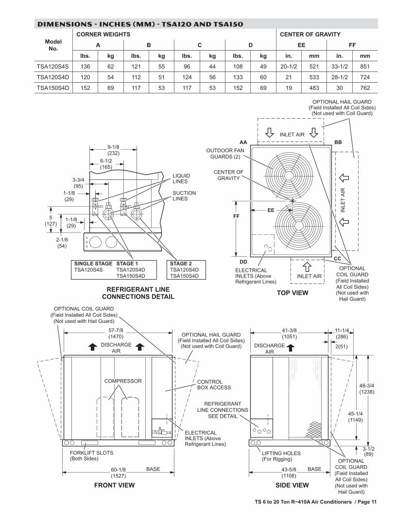
DIMENSIONS - INCHES (MM) - TSA120 AND TSA150
DISCHARGEAIR
REFRIGERANTLINE CONNECTIONS
SEE DETAIL
DISCHARGEAIR
41-3/8(1051)
LIFTING HOLES(For Rigging)
SIDE VIEW
43-5/8(1108)
48-3/4(1238)
3-1/2(89)
45-1/4(1149)
BASE60-1/8(1527)
57-7/8(1470)
COMPRESSOR
BASE
FRONT VIEW
FORKLIFT SLOTS(Both Sides)
CONTROLBOX ACCESS
ELECTRICAL INLETS (Above Refrigerant Lines)
TOP VIEW
FFEE IN
LET
AIR
INLET AIR
BBAA
CCDD
CENTER OFGRAVITY
ELECTRICALINLETS (AboveRefrigerant Lines)
OUTDOOR FANGUARDS (2)
INLET AIR
OPTIONALCOIL GUARD(Field InstalledAll Coil Sides)(Not used with
Hail Guard)
2(51)
OPTIONAL HAIL GUARD(Field Installed All Coil Sides)
(Not used with Coil Guard)
OPTIONAL HAIL GUARD(Field Installed All Coil Sides)
(Not used with Coil Guard)
5(127)
2-1/8(54)
9-1/8(232)
1-1/8(29)
3-3/4(95)
6-1/2(165)
SUCTIONLINES
LIQUIDLINES
SINGLE STAGETSA120S4S
STAGE 1TSA120S4DTSA150S4D
STAGE 2TSA120S4DTSA150S4D
1-1/8(29)
REFRIGERANT LINECONNECTIONS DETAIL
11-1/4(286)
(Not used withHail Guard)
OPTIONAL COIL GUARD(Field Installed All Coil Sides)
(Not used with Hail Guard)
OPTIONALCOIL GUARD(Field InstalledAll Coil Sides)
Model No.
CORNER WEIGHTS CENTER OF GRAVITY
A B C D EE FF
lbs. kg lbs. kg lbs. kg lbs. kg in. mm in. mm
TSA120S4S 136 62 121 55 96 44 108 49 20-1/2 521 33-1/2 851
TSA120S4D 120 54 112 51 124 56 133 60 21 533 28-1/2 724
TSA150S4D 152 69 117 53 117 53 152 69 19 483 30 762

TS 6 to 20 Ton R−410A Air Conditioners / Page 12
DIMENSIONS - INCHES (MM) - TSA180 AND TSA240
1-1/8(29)
DISCHARGEAIR
INLE
TA
IR
86-1/2(2197)
60-1/8(1527)
57-7/8(1470)
CONTROLBOX ACCESS
BASE
LIFTING HOLES(For Rigging)
FRONT VIEW
5(127)
2-1/8(54)
9-1/8(232)
1-1/8(29)
TOP VIEW
FORKLIFT SLOTS(Both Sides)
SIDE VIEW
88-3/4(2254)
48-3/4(1238)
3-1/2(89)
45-1/4(1149)
FF
EE
CENTER OFGRAVITY
AA BB
CCDD
3-3/4(95)
6-1/2(165)
BASE
COMPRESSOR
SUCTIONLINE (2)
LIQUIDLINE (2)
OUTDOOR FANGUARDS (4)
REFRIGERANT LINECONNECTIONS DETAIL
INLETAIR
INLETAIR
ELECTRICALINLETS (AboveRefrigerant Lines)
DISCHARGEAIR
REFRIGERANTLINE CONNECTIONS
SEE DETAIL
ELECTRICAL INLETS (Above Refrigerant Lines)
STAGE 1 STAGE 2
OPTIONAL COIL GUARD(Field Installed All Coil Sides)
(Not used with Hail Guard)
2(51)
OPTIONALHAIL GUARD(Field InstalledAll Coil Sides)(Not used with
Coil Guard)
OPTIONALHAIL GUARD(Field InstalledAll Coil Sides)(Not used with
Coil Guard)
11-1/4(286)
(Not used withHail Guard)OPTIONAL COIL GUARD
(Field Installed All Coil Sides)(Not used with Hail Guard)
OPTIONALCOIL GUARD(Field InstalledAll Coil Sides)
Model No.
CORNER WEIGHTS CENTER OF GRAVITY
A B C D EE FF
lbs. kg lbs. kg lbs. kg lbs. kg in. mm in. mm
TSA180S4D 223 101 166 75 178 81 238 108 29 737 38 965
TSA240S4D 265 120 197 89 197 89 265 120 30 762 38 965

TS 6 to 20 Ton R−410A Air Conditioners / Page 13
GUIDE SPECIFICATIONS
This Specification is for Lennox Industries T-Class, 6 to 20 Ton, outdoor air conditioner split system (TS series) units. Revise specification section number and title below to suit project requirements, specification practices and section content. Refer to CSI MasterFormat for other section numbers and titles.
Optional text or text requiring a decision is indicated by bold brackets [ ]; delete text not required in final copy of specification. Specifier Notes typically precede specification text; delete notes in final copy of specification. Trade/brand names with appropriate symbols typically are used in Specifier Notes; symbols are not used in specification text. Metric conversion, where used, is soft metric conversion.
SECTION 23 63 00 REFRIGERANT CONDENSERS
PART 1 GENERAL 1.01 SUMMARY
A. Section Includes: Split System Condensing Units.
Specifier Note: Revise paragraph below to suit project requirements. Add section numbers and titles per CSI MasterFormat and specifier’s practice.
B. Related Sections
Specifier Note: Article below may be omitted when specifying manufacturer’s proprietary products and recommended installation. Retain Reference Article when specifying products and installation by an industry reference standard. If retained, list standard(s) referenced in this section. Indicate issuing authority name, acronym, standard designation and title. Establish policy for indicating edition date of standard referenced. Conditions of the Contract or Division 1 References Section may establish the edition date of standards. This article does not require compliance with standard, but is merely a listing of references used. Article below should list only those industry standards referenced in this section. Retain only those reference standards to be used within the text of this Section. Add and delete as required for specific project.
1.02 REFERENCES A. Air-Conditioning, Heating and Refrigeration Institute (AHRI):
1. AHRI 270-95 Sound Rating of Outdoor Unitary Equipment. 2. AHRI 340/360 Commercial and Industrial Unitary Air-Conditioning and Heat Pump Equipment (ANSI
approved) B. Servicing Standards:
1. National Electric Code (NEC). 2. Underwriters Laboratories (UL). 3. Canadian Electric Code (CEC).
C. Units to be Department of Energy (DOE) ratedD. ISO 9001, units manufactured to quality standardE. Meet Minimum EPACT 2005, and addendums, efficiency levels
Specifier Note: Article below should be restricted to statements describing design or performance requirements and functional (not dimensional) tolerances of a complete system. Limit descriptions to composite and operational properties required to link components of a system together and to interface with other systems.
1.03 SYSTEM DESCRIPTION A. Performance Requirements:
1. Condensing Unit: [6, 7.5, 10, 12.5, 15 and 20 ton capacity]. 2. Electrical Characteristics:
a. 60 Hz.b. 3 phase.c. Voltage: [208/230 V] [460 V] [575 V].
Specifier Note: Article below includes submittal of relevant data to be furnished by Contractor before, during or after construction. Coordinate this article with Architect’s and Contractor’s duties and responsibilities in Conditions of the Contract and Division 1 Submittal Procedures Section.

TS 6 to 20 Ton R−410A Air Conditioners / Page 14
GUIDE SPECIFICATIONS
1.04 SUBMITTALS A. General: Submit listed submittals in accordance with Conditions of the Contract and Division 1 Submittal
Procedures.B. Product Data: Submit product data for specified products.C. Shop Drawings:
1. Submit shop drawings in accordance with Section [01330 - Submittal Procedures]. 2. Indicate:
a. Equipment, piping and connections, together with valves, strainers, control assemblies, thermostatic controls, auxiliaries and hardware and recommended ancillaries which are mounted, wired and piped ready for final connection to building system, its size and recommended bypass connections.
b. Piping, valves and fittings shipped loose showing final location in assembly. c. Control equipment shipped loose, showing final location in assembly. d. Field wiring diagrams. e. Dimensions, internal and external construction details, installation clearances, recommended
method of installation, sizes and location of mounting bolt holes. f. Detailed composite wiring diagrams for control systems showing factory installed wiring
and equipment on packaged equipment or required for controlling devices or ancillaries, accessories, controllers.
D. Quality Assurance:1. All units to be factory tested before shipping.2. Manufacturer’s Instructions: Manufacturer’s installation instructions.
Specifier Note: Coordinate paragraph below with Part 3 Field Quality Requirements Article herein. Retain or delete as applicable.
E. Closeout Submittals: Submit the following:1. Warranty: Warranty documents specified herein. 2. Operation and Maintenance Data: Operation and maintenance data for installed products in
accordance with Division 1 Closeout Submittals (Maintenance Data and Operation Data) Section. Include methods for maintaining installed products and precautions against cleaning materials and methods detrimental to finishes and performance. Include names and addresses of spare part suppliers.
3. Provide brief description of unit, with details of function, operation, control and component service.4. Commissioning Report: Submit commissioning reports, report forms and schematics in accordance
with Section 01810 - Commissioning.
1.05 QUALITY ASSURANCE A. Qualifications:
1. Installer experienced in performing work of this section who has specialized in installation of work similar to that required for this project.
2. Manufacturer Qualifications: Manufacturer capable of providing field service representation during construction and approving application method.
B. Preinstallation Meetings: Conduct pre-installation meeting to verify project requirements, manufacturer’s installation instructions and manufacturer’s warranty requirements. Comply with Division 1 Project Management and Coordination (Project Meetings).

TS 6 to 20 Ton R−410A Air Conditioners / Page 15
GUIDE SPECIFICATIONS
1.06 DELIVERY, STORAGE & HANDLING A. General: Comply with Division 1 Product Requirements. B. Ordering: Comply with manufacturer’s ordering instructions and lead time requirements to avoid construction
delays.C. Packing, Shipping, Handling and Delivery:
1. Deliver materials in manufacturer’s original, unopened, undamaged containers with identification labels intact.
2. Ship, handle and unload units according to manufacturer’s instructions. D. Storage and Protection:
1. Store materials protected from exposure to harmful weather conditions. 2. Factory shipping covers to remain in place until installation.
Specifier Note: Coordinate article below with Conditions of the Contract and with Division 1 Closeout Submittals (Warranty).
1.07 WARRANTY A. Project Warranty: Refer to Conditions of the Contract for project warranty provisions. B. Manufacturer’s Warranty: Submit, for Owner’s acceptance, manufacturer’s standard warranty document
executed by authorized company official. Manufacturer’s warranty is in addition to, and not a limitation of, other rights Owner may have under Contract Documents.
Specifier Note: Coordinate paragraph below with manufacturer’s warranty requirements.
C. Warranty: Commencing on Date of Installation.1. Compressor: 5 year limited (nonresidential applications).2. Other Covered Components: 1 year limited (nonresidential applications).
PART 2 PRODUCTS
Specifier Note: Retain article below for proprietary method specification. Add product attributes, performance characteristics, material standards and descriptions as applicable. Use of such phrases as “or equal” or “or approved equal” or similar phrases may cause ambiguity in specifications. Such phrases require verification (procedural, legal and regulatory) and assignment of responsibility for determining “or equal” products.
2.01 OUTDOOR CONDENSING UNITS A. Manufacturer: Lennox Industries.
1. Contact: 2100 Lake Park Blvd., Richardson, TX 75080; Telephone: (800) 453-6669; Web site: www.lennox.com.
B. Proprietary Products/Systems: TS Series, including the following equipment: 1. Cabinet:
a. Galvanized steelb. Pre-painted finishc. Refrigerant line connections to be located outside the unit d. Control access. e. All controls factory wired
2. Compressor: a. Scroll Typeb. Resiliently mounted on rubber mounts for vibration isolationc. Overload protectedd. Internal excessive current and temperature protection.e. Crankcase heaterf. 1 or 2 single speed compressor(s) per unit.
3. Refrigerant System a. General
1. Refrigerant: R410-A2. Fully serviceable liquid and suction line service valves.3. Gauge ports.
b. Refrigerant System:1. High pressure switch2. Loss of charge (low pressure) switch

TS 6 to 20 Ton R−410A Air Conditioners / Page 16
GUIDE SPECIFICATIONS
3. Hi-capacity driers 4. Outdoor Coil(s):
a. Aluminum rippled and lanced fins.b. Copper tube construction. c. Aluminum fins to be mechanically bonded to copper tubes.d. All coils to be high pressure leak tested at factory.
5. Outdoor Coil Fans/Air Mover: a. Direct drive, propeller type fan(s). b. Totally enclosed fan motors. c. Steel fan guards or fan guard. d. Fan service by removal of fan guard.
6. Controls: Low Ambient Operation, down to 30 °F7. [Field Installed Options/Accessories]:
a. Outdoor Coils:1. [Hail Guards: heavy duty metal mesh enclosures]2. [Coil Guards: heavy duty metal mesh]
b. Controls1. [L-Connection Network]2. [Low Ambient Control, down to 0 °F]3. [Thermostat]
2.02 PRODUCT SUBSTITUTIONS A. Substitutions: No substitutions permitted.
PART 3 EXECUTION 3.01 MANUFACTURER’S INSTRUCTIONS
Specifier Note: Revise article below to suit project requirements and specifier’s practice.
A. Compliance: Comply with manufacturer’s written data, including product technical bulletins, product catalog installation instructions and product carton installation instructions.
3.02 EXAMINATION A. Site Verification of Conditions: Verify substrate conditions, which have been previously installed under other
sections, are acceptable for product installation in accordance with manufacturer’s instructions. 3.03 INSTALLATION
A. Install Condensing Units in accordance with manufacturers instructions and regulations of authorities having jurisdiction.
END OF SECTION


REVISIONS
Sections Description of Change
Dimensions Revised dimensions for suction line connections.
NOTE - Due to Lennox’ ongoing commitment to quality, Specifications, Ratings and Dimensions subject to change without notice and without incurring liability. Improper installation, adjustment, alteration, service or maintenance can cause property damage or personal injury. Installation and service must be performed by a qualified installer and servicing agency. ©2011 Lennox Industries, Inc.
Visit us at www.lennox.com
For the latest technical information, www.lennoxcommercial.com
Contact us at 1-800-4-LENNOX