
07000 Thermal and Moisture Protection - Yale University · • Pools or fountains ... – Conforms...
33
Yale University Design Standards 07100 Waterproofing This document provides design standards only, and is not intended for use, in whole or in part, as a specification. Do not copy this information verbatim in specifications or in notes on drawings. Refer questions and comments regarding the content and use of this document to the Yale University Project Manager. CONTENTS A. Summary B. System Design and Performance Requirements C. Submittals D. Warranty E. Materials F. Quality Control A. Summary This section contains general design criteria for waterproofing. B. System Design and Performance Requirements 1. Waterproofing Locations Provide waterproofing at the following locations: • Below-grade at the perimeter of the structure in locations subject to hydrostatic pressure • Exterior decks or plazas that form a roof over enclosed space • Pools or fountains • Toilet rooms and shower floors over occupied areas • Mechanical room floors over occupied areas 2. General Performance Requirements a. Waterproofing systems must prevent the infiltration of water and moisture through specific building components. b. Waterproofing systems must show evidence of successful performance for a minimum of five years. c. Waterproofing systems must have extremely minimal permeability. d. Waterproofing systems must have extremely minimal emulsification or degradation in a constant water environment. Division 07000: Thermal and Moisture Protection 1 Revision 0, 04/05
Transcript of 07000 Thermal and Moisture Protection - Yale University · • Pools or fountains ... – Conforms...

Yale University Design Standards
07100 Waterproofing
This document provides design standards only, and is not intended for use, in whole or in part, as a specification. Do not copy this information verbatim in specifications or in notes on drawings. Refer questions and comments regarding the content and use of this document to the Yale University Project Manager.
CONTENTS A. SummaryB. System Design and Performance RequirementsC. SubmittalsD. WarrantyE. MaterialsF. Quality Control
A. Summary This section contains general design criteria for waterproofing.
B. System Design and Performance Requirements 1. Waterproofing Locations
Provide waterproofing at the following locations: • Below-grade at the perimeter of the structure in locations subject to hydrostatic
pressure • Exterior decks or plazas that form a roof over enclosed space • Pools or fountains • Toilet rooms and shower floors over occupied areas • Mechanical room floors over occupied areas
2. General Performance Requirements a. Waterproofing systems must prevent the infiltration of water and moisture
through specific building components. b. Waterproofing systems must show evidence of successful performance for a
minimum of five years. c. Waterproofing systems must have extremely minimal permeability. d. Waterproofing systems must have extremely minimal emulsification or
degradation in a constant water environment.
Division 07000: Thermal and Moisture Protection 1 Revision 0, 04/05
Yale University Design Standards Section 07100: Waterproofing
e. Waterproofing systems must have high elasticity. f. Waterproofing systems must have crack bridging capability. g. Waterproofing systems must exhibit leak location characteristics by preventing
the migration of water under the waterproofing. h. All waterproofing system components must be compatible products as
recommended by the manufacturer. The components must be applied according to the manufacturer’s instructions.
i. All waterproofing membranes, except fluid, sprayed, or crystalline materials, must be terminated with a non-corrosive metal bar. The bar must be subject to the membrane manufacturer’s approval.
j. Waterproofing systems must resist the effects of de-icing chemicals. k. Waterproofing systems must have watertight compatibility at tie-ins to existing
systems. l. Fumes must be minimized during installation.
3. Specific Performance Requirements Whenever possible and appropriate, the waterproofing system for a given condition must respond to project-specific needs, including the following. a. Below-grade perimeter wall waterproofing subject to hydrostatic pressure must
have the following characteristics: • High-static loading (so drainage composite sheet dimples are not driven
into the insulation, damaging the membrane itself) • Structural integrity that is greater than the structural burden, including
anticipated live loading. b. Mechanical room floor waterproofing over occupied areas must have the
following characteristics. • Resistance to wear from foot traffic • Slip resistance when wet or dry
Division 07000: Thermal and Moisture Protection 2 Revision 0, 04/05
Yale University Design Standards Section 07100: Waterproofing
C. Submittals Submit the following design and construction documents to Yale University.
1. Design Documents a. Submit documentation of the intended systems for review that includes the
following: • An understanding of the conditions that require waterproofing • A description of the system to be installed • Materials to be used • Evidence of successful applications
b. Details of each typical waterproofing condition must be drawn at large scale, so that all components are clearly shown and labeled.
2. Construction Documents a. Submit product data for all waterproofing materials. Include material, warranty,
and installation instructions. b. Submit installer certification that the manufacturer has provided training in the
installation of warranted waterproofing materials.
D. Warranty Warranties must cover the entire cost of repairs or replacement of defective work during the warranty period, including the costs associated with exposing the waterproofing and replacing all materials.
Division 07000: Thermal and Moisture Protection 3 Revision 0, 04/05
Yale University Design Standards Section 07100: Waterproofing
E. Materials Waterproofing materials for specific applications must conform to the following standards.
1. Below-Grade Waterproofing Below-grade waterproofing materials may include the following: • Asphalt/polyethylene sheet consisting of a self-adhering, rubberized asphalt
membrane bonded to polyethylene sheeting – At least 0.060" thick, with 0.004" polyethylene film – Bituthene manufactured by W.R. Grace and Company or an approved
equivalent
• Thermoplastic membrane consisting of polyvinyl chloride (PVC) flexible sheets
– Conforms to ASTM D4434 standards – Manufactured by Sarnafil Waterproofing Systems, Inc
• Bentonite waterproofing consisting of Volclay Type 1 panels – Manufactured by American Colloid Company or an approved equivalent
• Primer – Rubber based type – Free of toxic solvents – Compatible with waterproofing
• Prefabricated geocomposite drainage core – High impact polymeric drain core – Flow channels on one side – Filter fabric bonded to the molded dimples
• Protection board consisting of 1/8" thick asphaltic core – PC-2 protection board manufactured by WR Meadows, Inc. or an approved
equivalent
2. Exterior Plaza Waterproofing The designer must provide a waterproofing recommendation for approval by Yale University.
Division 07000: Thermal and Moisture Protection 4 Revision 0, 04/05

Yale University Design Standards Section 07100: Waterproofing
3. Pool and/or Fountain Waterproofing The designer must provide a waterproofing recommendation for approval by Yale University.
4. Toilet Room and Shower Floor Waterproofing Use a cold-applied, liquid rubber membrane and reinforcing fabric by Laticrete 9235. Use a polyethylene membrane system by Schluter-DITRA, or an approved equivalent.
5. Mechanical Room Floor Waterproofing The designer must provide a waterproofing recommendation for approval by Yale University.
F. Quality Control 1. Yale University may require a full-time waterproofing consultant during the
construction phase to observe critical waterproofing operations. 2. Horizontal waterproofing surfaces with occupied space below must be flood-tested
before back-filling or other overburden installation. To ensure that university property is not damaged during flood testing, the contractor must have personnel on-site during the entire flood test.
End of Section
Division 07000: Thermal and Moisture Protection 5 Revision 0, 04/05
Yale University Design Standards
07200 Thermal Insulation
This document provides design standards only, and is not intended for use, in whole or in part, as a specification. Do not copy this information verbatim in specifications or in notes on drawings. Refer questions and comments regarding the content and use of this document to the Yale University Project Manager.
CONTENTS A. SummaryB. System Design and Performance RequirementsC. Materials
A. Summary This section provides general design criteria for the specification of thermal insulation.
B. System Design and Performance Requirements Due to the evolving nature of the building industry, Yale University encourages, and will review, alternative methods of thermal insulation. Provide minimum insulation values that meet or exceed project program, code, or Yale University design standards.
C. Materials Thermal insulation materials must conform to the following standards.
1. Glass Fiber Blanket or Batt Type Insulation Provide the following types of glass fiber blanket or batt insulation manufactured by Owens Corning Fiberglass Corp—or an approved equivalent: • Unfaced, • Paper-faced (vapor barrier) • Foil-faced (vapor barrier)
Division 07000: Thermal and Moisture Protection 6 Revision 0, 04/05
Yale University Design Standards Section 07200: Thermal Insulation
2. Board Type Insulation Provide extruded, polystyrene insulation—Styrofoam manufactured by Dow Chemical, Formular insulation manufactured by UC Industries, or an approved equivalent, with the following compressive strengths. • 20 psi at foundations and under slab-on-grade • 60 psi at decks • 100 psi under heavy vehicular traffic
3. Loose Fill Type Insulation At masonry block cavities, provide granular perlite or vermiculite insulation, treated against vermin and insects.
4. Roof and Deck Insulation a. Provide insulation that is compatible with the roof membrane and is
recommended by the manufacturer to maintain a system warranty. b. Install at least two staggered layers of insulation. c. Expanded polystyrene and lightweight concrete fill are not acceptable unless
approved.
5. Vapor/Air Barrier On the warm side of the exterior wall, install flame retardant polyethylene sheets of 4-mil minimum thickness. Seal the sheet joints with flame-retardant, self-adhering, polyethylene tape, with a 2" minimum width.
End of Section
Division 07000: Thermal and Moisture Protection 7 Revision 0, 04/05
Yale University Design Standards
07250 Sprayed Fireproofing
This document provides design standards only, and is not intended for use, in whole or in part, as a specification. Do not copy this information verbatim in specifications or in notes on drawings. Refer questions and comments regarding the content and use of this document to the Yale University Project Manager.
CONTENTS A. SummaryB. SubmittalsC. System Design and Performance RequirementsD. ManufacturersE. AccessoriesF. Installation GuidelinesG. Quality ControlH. CleaningI. Warranty
A. Summary This section contains general design criteria for spray-applied fireproofing. The following requirements apply to spray fireproofing used in the protection of structural steel members as required by applicable local building codes.
B. Submittals Provide a schedule in the specification section or on the drawings that identifies the structural components requiring fireproofing, the required hourly rating, and the appropriate UL design.
C. System Design and Performance Requirements Sprayed fireproofing must conform to the following general requirements and design criteria.
1. General Requirements a. Cementitious spray fireproofing must be factory mixed, blended for uniform
texture, and composed of non-fibrous materials. b. Fireproofing materials must demonstrate the following surface burning
characteristics when tested in accordance with ASTM E84: • Flame spread: 0 • Smoke developed: 0
c. Sprayed-on, mineral fiber fireproofing is not acceptable.
Division 07000: Thermal and Moisture Protection 8 Revision 0, 04/05
Yale University Design Standards Section 07250: Sprayed Fireproofing
2. Density Criteria a. At locations where sprayed fireproofing is concealed by permanent
construction, provide a minimum average density of 15 lb/cu ft (175 kg/cu m), or as listed in the UL Resistance Directory for each rating indicated, whichever is greater.
b. At interior locations where sprayed fireproofing is exposed to the air, but out of reach of building occupants (above 10 ft (3 m) from the floor), provide a minimum average density of 15 lb/cu ft (224 kg/cu m), or as listed in the UL Resistance Directory for each rating indicated, whichever is greater.
c. At exterior locations where sprayed fireproofing is exposed to the air but out of reach of building occupants (above 10 ft (3 m) from the ground), provide a minimum density of 21 lb/cu ft (340 kg/cu m) and a moisture resistance not affected by precipitation or freeze-thaw.
d. At exposed exterior and interior locations within reach of building occupants (below 10 ft (3 m)), provide a minimum density of 39 lb/cu ft (625 kg/cu m) and a moisture resistance not affected by precipitation or freeze-thaw.
3. Specific Design Criteria a. The minimum average bond strength must be 200 psf. The minimum individual
bond strength must be 150 psf when measured in accordance with ASTM E736 test standards.
b. In accordance with ASTM E760 test standards, cracking, flaking, or de-lamination must not occur from impact.
c. In accordance with ASTM E605 test standards, the minimum average dry density must be equal to that listed in the UL Fire Resistance Directory.
d. In accordance with ASTM E761 test standards, fireproofing material must deform a maximum of 10% when subjected to forces of 1000 psf.
e. In accordance with ASTM E937 test standards, fireproofing material must not corrode surfaces to which it is applied.
f. The maximum allowable weight loss of fireproofing material due to air erosion must be less than 0.005 gm/ft2 when measured in accordance with ASTM E859 test standards.
g. No more than 15 cm3 can be abraded or removed from the fireproofing material when tested in accordance with test methods developed by the City of San Francisco, Bureau of Building Inspection.
Division 07000: Thermal and Moisture Protection 9 Revision 0, 04/05

Yale University Design Standards Section 07250: Sprayed Fireproofing
D. Manufacturers Subject to compliance with the design requirements, provide products by one of the following manufacturers: • W.R. Grace and Company • Isolatek International Corporation
E. Accessories Provide metal lath as necessary for specific project conditions.
F. Installation Guidelines 1. Mix and apply fireproofing in strict accordance with the fireproofing manufacturer's
instructions. 2. Apply fireproofing in sufficient thickness to achieve the required rating. 3. Patch damaged areas as necessary.
G. Quality Control Structural testing and inspection must be performed by qualified parties. Testing may be performed to verify fireproofing thickness and density in accordance with ASTM E605 test standards.
H. Cleaning Remove excess material, overspray, droppings, and debris. Remove fireproofing from surfaces not specifically required to be fireproofed.
I. Warranty Provide a two-year warranty stating that applied fireproofing will remain free from cracks, checking, dusting, flaking, spalling, separation, and blistering. Reinstall or repair fireproofing in such instances of failure in performance.
End of Section
Division 07000: Thermal and Moisture Protection 10 Revision 0, 04/05
Yale University Design Standards
07270 Firestopping
This document provides design standards only, and is not intended for use, in whole or in part, as a specification. Do not copy this information verbatim in specifications or in notes on drawings. Refer questions and comments regarding the content and use of this document to the Yale University Project Manager.
CONTENTS A. SummaryB. System Design and Performance RequirementsC. SubmittalsD. Product StandardsE. MaterialsF. PreparationG. Installation Guidelines
A. Summary This section contains general design criteria for firestopping.
B. System Design and Performance Requirements 1. Firestopping must be specified and detailed as required by building codes.
Firestopping must consist of furnishing and installing a material or a combination of materials to form an effective barrier against the spread of flame, smoke, and gases, and to maintain the integrity of fire resistance rated walls, partitions, floors, and ceiling assemblies, including through-penetrations and construction joints. Through-penetrations include the annular spaces around pipes, tubes, conduit, wires, cables, and vents. Construction joints include those used to accommodate expansion, contraction, wind, or seismic movement. Firestopping material must not interfere with the required movement of the joint.
2. A single manufacturer must supply all firestopping materials, which must be compatible with adjacent building components.
3. The building code official may review and approve all firestopping and smokestopping measures.
Division 07000: Thermal and Moisture Protection 11 Revision 0, 04/05

Yale University Design Standards Section 07270: Firestopping
C. Submittals Submit the following design and construction documents to Yale University.
1. Design Documents Provide details of all firestopping and smokestopping conditions as part of the construction documents.
2. Construction Documents a. Submit detail drawings including manufacturer’s data, typical details,
installation instructions, and fire test data and/or a report. b. Submit certificates attesting that firestopping material complies with the project
specifications. For example, an Underwriters Laboratory label or listing, or a written certificate from a nationally-recognized testing agency stating that the items have been tested and conform to specified requirements.
D. Product Standards 1. ASTM E 84 – Surface Burning Characteristics of Building Materials 2. ASTM E 119 – Method for Fire Tests of Building Construction and Materials 3. ASTM E 814 – Fire Tests of Through-Penetration Fire Stops 4. NFPA 101 – Life Safety Code 5. UL 05 – Fire Resistance Directory 6. UL 263 – Fire Tests of Building Construction and Materials 7. UL 723 – Test for Surface Burning Characteristics of Building Materials 8. US 1479 – Fire Tests of Through-Penetration Firestops
Division 07000: Thermal and Moisture Protection 12 Revision 0, 04/05

Yale University Design Standards Section 07270: Firestopping
E. Materials Firestopping materials must conform to the following standards.
1. Fire Stop and Joint Sealant Systems Use a single-component silicone sealant by Dow Corning, Bio Fireshield, Inc., or approved equivalent material.
2. Intumescent Materials Use materials capable of expanding up to 10 times when exposed to temperatures over 250°F. Use a non-corrosive material by 3M, Bio Fireshield, Flame Stop, or approved equivalent that is compatible with synthetic cable jackets.
3. Silicone Foam Sealant Use a two-component foam silicone sealant by Dow Corning, or an approved equivalent material.
4. Firestopping Pillows Use SpecSeal SSB pillows by Specified Technologies, Inc., Metacaulk firestop Pillows by RectorSeal Corporation, or approved equivalent material.
5. Devices Use UL-tested/listed devices recommended by the manufacturer for the intended use.
6. Mortar Use: UL-tested/listed mortar mix.
7. Packing Use loose fill, blanket or board forms alumina-silica or ceramic fiber packing, which is rated to a minimum of 2000°F.
8. Fire-Safing Insulation Use fire-safing insulation of a minimum 4 lb/ft3 density and a minimum 2000°F melt point.
Division 07000: Thermal and Moisture Protection 13 Revision 0, 04/05
Yale University Design Standards Section 07270: Firestopping
F. Preparation Clean substrate of dirt, dust, grease, oil, mill scale, or other material that may affect the firestopping bond. Starting installation of the firestopping constitutes acceptance of the surface compatibility and the condition of the substrate.
G. Installation Guidelines 1. Install firestopping materials strictly in accordance with the material manufacturer’s
instructions and the rated design. 2. Firestopping areas must not be covered or enclosed until inspection is complete and
approved. A manufacturer's representative must perform initial and periodic inspections of firestopping applications during the work to ensure adherence to the manufacturer's instructions and specified requirements.
End of Section
Division 07000: Thermal and Moisture Protection 14 Revision 0, 04/05
Yale University Design Standards
07300 Asphalt Shingles and Roof Tiles
This document provides design standards only, and is not intended for use, in whole or in part, as a specification. Do not copy this information verbatim in specifications or in notes on drawings. Refer questions and comments regarding the content and use of this document to the Yale University Project Manager.
CONTENTS A. SummaryB. System Design and Performance RequirementsC. SubmittalsD. Product StandardsE. MaterialsF. Accessories or Special FeaturesG. Extra MaterialsH. Special RequirementsI. Installation Guidelines
A. Summary This section contains general design criteria for asphalt shingles and roof tiles.
B. System Design and Performance Requirements Do not use asphalt singles or roof tiles on slopes less than 3:12.
C. Submittals All typical flashing, corners, edges, gutters, valleys, dormers, ridges, and penetrations on roofs must be drawn at large scale as part of the construction documents.
D. Product Standards 1. Fiberglass asphalt shingles:
• ASTM D3018 • Type 1 • UL Class A • Minimum 25 year warranty
2. Slate roof shingles: • ASTM C406 • Grade S1 • Hard, dense, sound commercial standard slate
Division 07000: Thermal and Moisture Protection 15 Revision 0, 04/05

Yale University Design Standards Section 07300: Asphalt Shingles and Roof Tiles
3. Clay roof tiles: • ASTM C1167 • Grade 1 • Vitrified clay tile and special trim tile
E. Materials 1. Roofing felt:
• ASTM D226 or ASTM D2626 • Unperforated • Asphalt felt • Use 15 or 30 lb felt for asphalt or organic shingles • Use 40 lb felt for roof tiles
2. Fasteners: • 11 gauge, ring shank copper nails for slate and tile • Hot-dipped galvanized roofing nails for shingles, with a minimum 3/8"
diameter head • Staples are not acceptable
3. Ice and water protection: • Sheet membrane of rubberized asphalt bonded to sheet polyethylene • 40 mil total membrane thickness
4. Plastic cement: • ASTM D2822 • Asphaltic type with mineral fiber components
5. Mortar: • ASTM C270 • Type N • Cement/lime mortar • Masonry cement is not permitted.
F. Accessories or Special Features Provide aesthetically appropriate gutters and downspouts where water runoff will affect pedestrian traffic.
Division 07000: Thermal and Moisture Protection 16 Revision 0, 04/05
Yale University Design Standards Section 07300: Asphalt Shingles and Roof Tiles
G. Extra Materials 1. Provide at least three unopened bundles of additional shingles in each color. Yale
University will specify the delivery location. 2. Deliver the quantity of slate or clay tiles specified by Yale University to the
specified location.
H. Special Requirements Provide special provisions for steep slope roofs as required by the manufacturer and/or local codes.
I. Installation Guidelines 1. Install asphalt shingles, slate shingles, and clay tiles over dry surfaces free of
ridges, warps, and voids. 2. Install ice and water protection according to manufacturer’s instructions and local
building codes. In addition, install ice and water shield at eaves, valleys, walls and dormers.
3. Provide a mock-up for roof tile installations. 4. Follow the manufacturer’s instructions for attaching asphalt shingles. 5. Provide a starter course for asphalt shingles at eaves, 1/2" beyond the fascia. 6. Extend asphalt shingles 1/2" beyond the face of rake edge fascia boards.
End of Section
Division 07000: Thermal and Moisture Protection 17 Revision 0, 04/05

Yale University Design Standards
07500 Membrane Roofing and Roof Insulation
This document provides design standards only, and is not intended for use, in whole or in part, as a specification. Do not copy this information verbatim in specifications or in notes on drawings. Refer questions and comments regarding the content and use of this document to the Yale University Project Manager.
CONTENTS A. SummaryB. System Design and Performance RequirementsC. MaterialsD. Roof InsulationE. Accessories or Special Features
A. Summary This section contains general design criteria for membrane roofing and roof insulation.
B. System Design and Performance Requirements Membrane roofing systems must meet the quality standards contained the National Roofing Contractors Association roofing and waterproofing manual.
1. Minimum Roof Slope a. Low-sloped roofs are defined as having a minimum of 1/4"/ft (1:48 pitch).
Dead-level roofs are not permitted. b. Steep roofs are defined as having a minimum of 3/12 pitch. c. Water conductors or rain water leaders must slope at least 1/8"/ft (1:100).
2. Roof Movement a. Roof designs must allow for expansion and contraction as required by the
building design or membrane used. b. Provide control joints that divide roofs into areas not exceeding 150' in length in
either direction. Provide full-height, wood blocking expansions joints where there are building expansion joints.
Division 07000: Thermal and Moisture Protection 18 Revision 0, 04/05
Yale University Design Standards Section 07500: Membrane Roofing and Roof Insulation
3. Ease of Service a. Roof systems must be inspectable and maintainable. b. All roofing components (not just roof covering) must be easily accessible by
maintenance personnel on foot, without the use of portable ladders or other portable devices.
c. Rooftop fixtures must be serviceable by means of simple parts replacement, minimizing the time required on the roof, and eliminating the need for repair work in inclement weather.
d. Provide walking surfaces from the rooftop access to, and around, the perimeter of roof-mounted equipment.
4. Roof Security a. Consider the roof area and all roof openings as unsupervised. b. Fixed homogeneous elements must have a Class I forced entry resistance rating
in accordance with ASTM F 1233. c. Roof openings and assemblies must have at least a Class I forced entry
resistance rating in accordance with ASTM F 1233 and a Grade 10 rating in accordance with ASTM F 476 (R96), adapted to suit the assembly.
5. Grease and Chemical Resistance Wherever grease, oils, or chemicals might be introduced onto the roof, provide roofing materials that are not damaged by such leakage.
6. Ice Design to avoid damage due to ice formation and buildup on roofing and in water conductors.
7. Membranes protection Except for EPDM & PVC roofs, all membranes must be protected.
8. Existing Roofs a. Preserve existing roofing elements in accordance with the project program. New
roofs must match adjacent existing roofs. b. Remove existing roofing elements for new construction in accordance with the
project program. c. Unless otherwise recommended or permitted, remove existing roofing down to
Division 07000: Thermal and Moisture Protection 19 Revision 0, 04/05

Yale University Design Standards Section 07500: Membrane Roofing and Roof Insulation
the decking. d. Inspect and clean existing leaders. Replace existing drains and leaders when
necessary. Provide for redundancy in the drainage system. e. Where deficient, increase the roof system's thermal efficiency. f. Check the load capacity of the existing roof structure to ensure that it can
accommodate the proposed roof.
9. High Humidity Environments a. When roofing over a high humidity environment, provide a vapor barrier on the
warm side of the roof insulation. In accordance with ASTM E-96, Procedure A, provide a two-ply, built-up roof barrier, with a vapor transmission rating that does not exceed 0.25 perms.
b. Do not apply a combustible vapor barrier directly to a metal deck.
10. Roofing Accessories a. Roof-mounted equipment must rest on curbs that are at least 8" high and extend
8" above the roof membrane. Coordinate the design with mechanical systems to ensure adequate accessibility for maintenance.
b. Roof penetrations for pipes and ducts must have sleeves that are at least 8" high, boots or curbs with overlapping flashing, and hoods and/or drawbands with caulking flanges. Sleeves, boots, and curbs must be properly flashed and tied into the roofing system.
C. Materials Provide membrane roofing and roof insulation materials that conform to the following standards. Inverted roof membrane assemblies are not permitted.
1. Asphalt System • Four-ply asphalt roofing system, with asphalt-saturated, glass-fiber felts • Manufactured by Bird, Celotex Corp., GAF, or an approved equivalent • Clean, smooth river gravel conforming to ASTM D 1863 specifications • 20-year system warranty
2. Coal-Tar System • Four -ply coal-tar system, with asphalt-saturated organic felts • Manufactured by Allied Signal (Black Armor) or an approved equivalent
Division 07000: Thermal and Moisture Protection 20 Revision 0, 04/05

Yale University Design Standards Section 07500: Membrane Roofing and Roof Insulation
• Clean, smooth river gravel conforming to ASTM D 1863 specifications • 20-year system warranty
3. Modified Bituminous Membrane Roofing System—Non-Ballasted • 160-mil thick, SBS modified bituminous sheet roofing membrane • Manufactured by Johns Manville or an approved equivalent • MBR cold application adhesive • Flashing material same as the roofing sheet • 20-year warranty
4. Other Roofing Systems • Other roofing systems approved by Yale University
D. Roof Insulation 1. Insulation must have a five-year performance record. Tapered insulation must
conform to a 45° or 60° layout. 2. The roof system design must not cause the dew point to occur at or near the surface
of the roof deck. 3. Roof areas must be sloped for positive drainage. 4. Bituminous membrane roofing systems must be rigid, glass fiber boards with an
integrally-bonded top covering of saturated felt or Kraft paper. 5. Single-ply membrane systems must conform to the following standards.
a. Isocyanurate insulation board: • Faced on both sides • Density of 2 lbs/ft3 • Minimum compressive strength of 25 psi • Insulation value of k = 0.15 • Manufactured by NRG Barriers, Inc. (Barrier Board) or an approved
equivalent b. Extruded polystyrene:
• Compressive strength of 20 psi • Manufactured by Dow Chemical (STYROFOAM) or an approved
equivalent
Division 07000: Thermal and Moisture Protection 21 Revision 0, 04/05

Yale University Design Standards Section 07500: Membrane Roofing and Roof Insulation
E. Accessories or Special Features 1. Provide prefabricated, concrete walkway pavers for roofing use. 2. Provide prefabricated curbs manufactured by Conn-Fab or an approved equivalent.
End of Section
Division 07000: Thermal and Moisture Protection 22 Revision 0, 04/05

Yale University Design Standards
07530 Single-Ply Membrane Roofing
This document provides design standards only, and is not intended for use, in whole or in part, as a specification. Do not copy this information verbatim in specifications or in notes on drawings. Refer questions and comments regarding the content and use of this document to the Yale University Project Manager.
CONTENTS A. SummaryB. System Design and Performance RequirementsC. MaterialsD. Roof InsulationE. Accessories or Special Features
A. Summary This section contains general design criteria for elastomeric roofing and roof insulation.
B. System Design and Performance Requirements Elastomeric roofing systems must meet the quality standards contained the National Roofing Contractors Association roofing and waterproofing manual.
1. Minimum Roof Slope a. Low-sloped roofs are defined as having a minimum of slope of 1/4"/ft
(1:48 pitch). Dead-level roofs are not permitted. b. Steep roofs are defined as having a minimum of 3/12 pitch. c. Water conductors or rain water leaders must slope at least 1/8"/ft (1:100).
2. Roof Movement a. Roof designs must allow for expansion and contraction as required by the
building design or membrane used. b. Provide control joints that divide roofs into areas not exceeding 150' in length in
either direction. Provide full-height, wood blocking expansions joints where there are building expansion joints.
Division 07000: Thermal and Moisture Protection 23 Revision 0, 04/05

Yale University Design Standards Section 07530: Single-Ply Membrane Roofing
3. Ease of Service a. Roof systems must be inspectable and maintainable. b. All roofing components (not just roof covering) must be easily accessible by
maintenance personnel on foot, without the use of portable ladders or other portable devices.
c. Rooftop fixtures must be serviceable by means of simple parts replacement, minimizing the time required on the roof, and eliminating the need for repair work in inclement weather.
d. Provide walking surfaces from the rooftop access to, and around, the perimeter of roof-mounted equipment.
4. Roof Security a. Consider the roof area and all roof openings as unsupervised. b. Fixed homogeneous elements must have a Class I forced entry resistance rating
in accordance with ASTM F 1233. c. Roof openings and assemblies must have at least a Class I forced entry
resistance rating in accordance with ASTM F 1233 and a Grade 10 rating in accordance with ASTM F 476 (R96), adapted to suit the assembly.
5. Grease and Chemical Resistance Wherever grease, oils, or chemicals might be introduced onto the roof, provide roofing materials that are not damaged by such leakage.
6. Ice Design to avoid damage due to ice formation and buildup on roofing and in water conductors.
7. Membranes protection Except for EPDM & PVC roofs, all membranes must be protected.
8. Existing Roofs a. Preserve existing roofing elements in accordance with the project program. New
roofs must match adjacent existing roofs. b. Remove existing roofing elements for new construction in accordance with the
project program. c. Unless otherwise recommended or permitted, remove existing roofing down to
Division 07000: Thermal and Moisture Protection 24 Revision 0, 04/05

Yale University Design Standards Section 07530: Single-Ply Membrane Roofing
the decking. d. Inspect and clean existing leaders. Replace existing drains and leaders when
necessary. Provide for redundancy in the drainage system. e. Where deficient, increase the roof system's thermal efficiency. f. Check the load capacity of the existing roof structure to ensure that it can
accommodate the proposed roof.
9. High Humidity Environments a. When roofing over a high humidity environment, provide a vapor barrier on the
warm side of the roof insulation. In accordance with ASTM E-96, Procedure A, provide a barrier with a vapor transmission rating that does not exceed 0.25 perms.
b. Do not apply a combustible vapor barrier directly to a metal deck.
10. Roofing Accessories a. Roof-mounted equipment must rest on curbs that are at least 8" high and extend
8" above the roof membrane. Coordinate the design with mechanical systems to ensure adequate accessibility for maintenance.
b. Roof penetrations for pipes and ducts must have sleeves that are at least 8" high, boots or curbs with overlapping flashing, and hoods and/or drawbands with caulking flanges. Sleeves, boots, and curbs must be properly flashed and tied into the roofing system.
C. Materials Provide membrane roofing and roof insulation materials that conform to the following standards. Inverted roof membrane assemblies are not permitted.
1. Elastomeric Single-Ply Membrane Roofing System—Loose-Laid Ballasted or Mechanically Fastened • EPDM 45-mil thick membrane • Manufactured by Carlise Syn Tec Systems (Sure-Seal Design B) or an
approved equivalent • Clean, smooth riverbed gravel; diameter and weight based on wind loading • Non-penetrating anchors; size and spacing based on wind loading • Uncured neoprene flashing • 15-year warranty
Division 07000: Thermal and Moisture Protection 25 Revision 0, 04/05
Yale University Design Standards Section 07530: Single-Ply Membrane Roofing
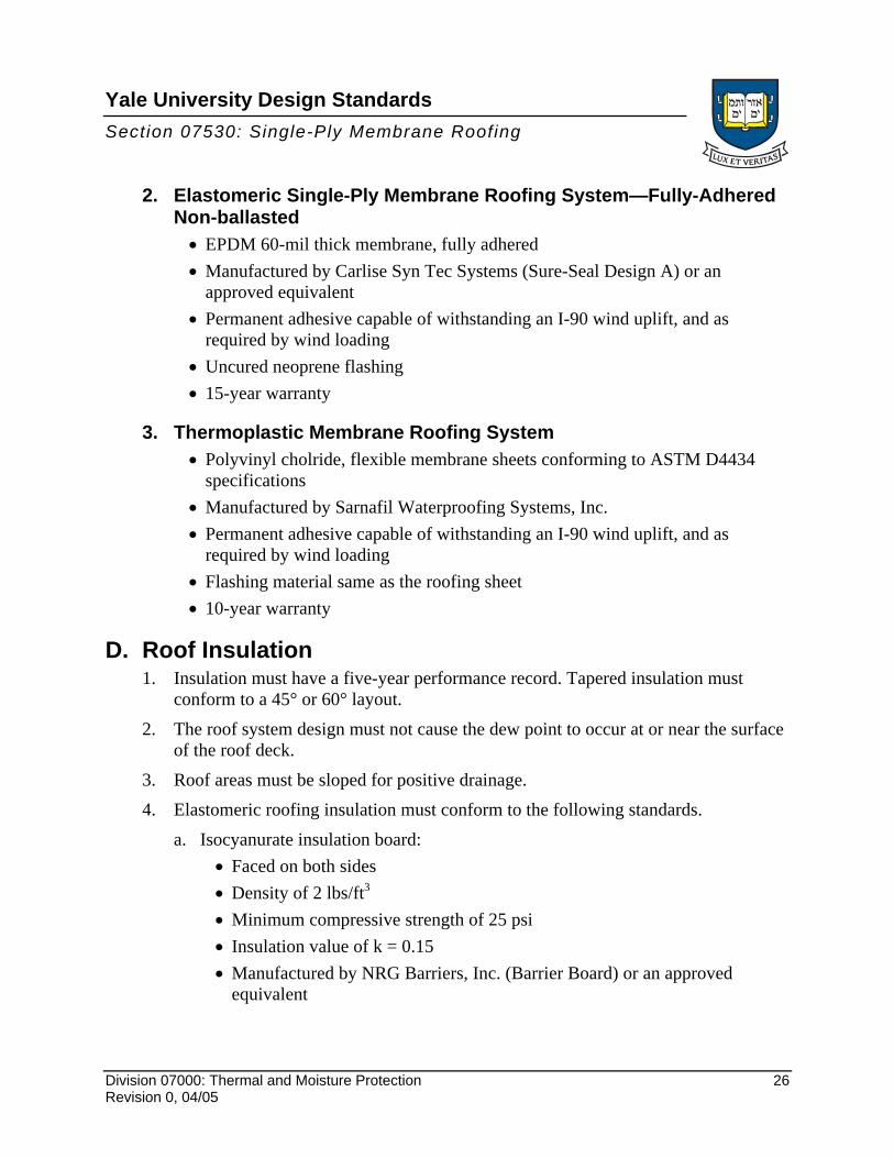
2. Elastomeric Single-Ply Membrane Roofing System—Fully-Adhered Non-ballasted • EPDM 60-mil thick membrane, fully adhered • Manufactured by Carlise Syn Tec Systems (Sure-Seal Design A) or an
approved equivalent • Permanent adhesive capable of withstanding an I-90 wind uplift, and as
required by wind loading • Uncured neoprene flashing • 15-year warranty
3. Thermoplastic Membrane Roofing System • Polyvinyl cholride, flexible membrane sheets conforming to ASTM D4434
specifications • Manufactured by Sarnafil Waterproofing Systems, Inc. • Permanent adhesive capable of withstanding an I-90 wind uplift, and as
required by wind loading • Flashing material same as the roofing sheet • 10-year warranty
D. Roof Insulation 1. Insulation must have a five-year performance record. Tapered insulation must
conform to a 45° or 60° layout. 2. The roof system design must not cause the dew point to occur at or near the surface
of the roof deck. 3. Roof areas must be sloped for positive drainage. 4. Elastomeric roofing insulation must conform to the following standards.
a. Isocyanurate insulation board: • Faced on both sides • Density of 2 lbs/ft3 • Minimum compressive strength of 25 psi • Insulation value of k = 0.15 • Manufactured by NRG Barriers, Inc. (Barrier Board) or an approved
equivalent
Division 07000: Thermal and Moisture Protection 26 Revision 0, 04/05

Yale University Design Standards Section 07530: Single-Ply Membrane Roofing
b. Extruded polystyrene: • Compressive strength of 20 psi • Manufactured by Dow Chemical (STYROFOAM) or an approved
equivalent
E. Accessories or Special Features 1. Provide prefabricated, concrete walkway pavers for roofing use. Provide an
additional wear sheet of EPDM under the pavers. 2. Provide prefabricated curbs manufactured by Conn-Fab or an approved equivalent.
End of Section
Division 07000: Thermal and Moisture Protection 27 Revision 0, 04/05

Yale University Design Standards
07600 Flashing and Sheet Metal
This document provides design standards only, and is not intended for use, in whole or in part, as a specification. Do not copy this information verbatim in specifications or in notes on drawings. Refer questions and comments regarding the content and use of this document to the Yale University Project Manager.
CONTENTS A. SummaryB. System Design and Performance RequirementsC. SubmittalsD. Product StandardsE. MaterialsF. Accessories or Special FeaturesG. PreparationH. Installation Guidelines
A. Summary This section contains general design criteria for flashing and sheet metal.
B. System Design and Performance Requirements 1. Copper flashing materials are used predominately in a wide variety of conditions. 2. The use of pre-finished, galvanized steel flashing is prohibited on a waterproofing
project where it extends below grade or below the wearing surface. 3. Seal all cast iron vents with lead jacketing. 4. Sheet metal work must comply with the requirements in the SMACNA architectural
sheet metal manual. 5. Flashing and sheet metal work must physically protect related work from damage
that would permit water leakage to the building interior. 6. Roof perimeter flashing installations must meet FM 1-49 requirements.
C. Submittals All details related to flashing must be drawn at large scale.
Division 07000: Thermal and Moisture Protection 28 Revision 0, 04/05
Yale University Design Standards Section 07600: Flashing and Sheet Metal
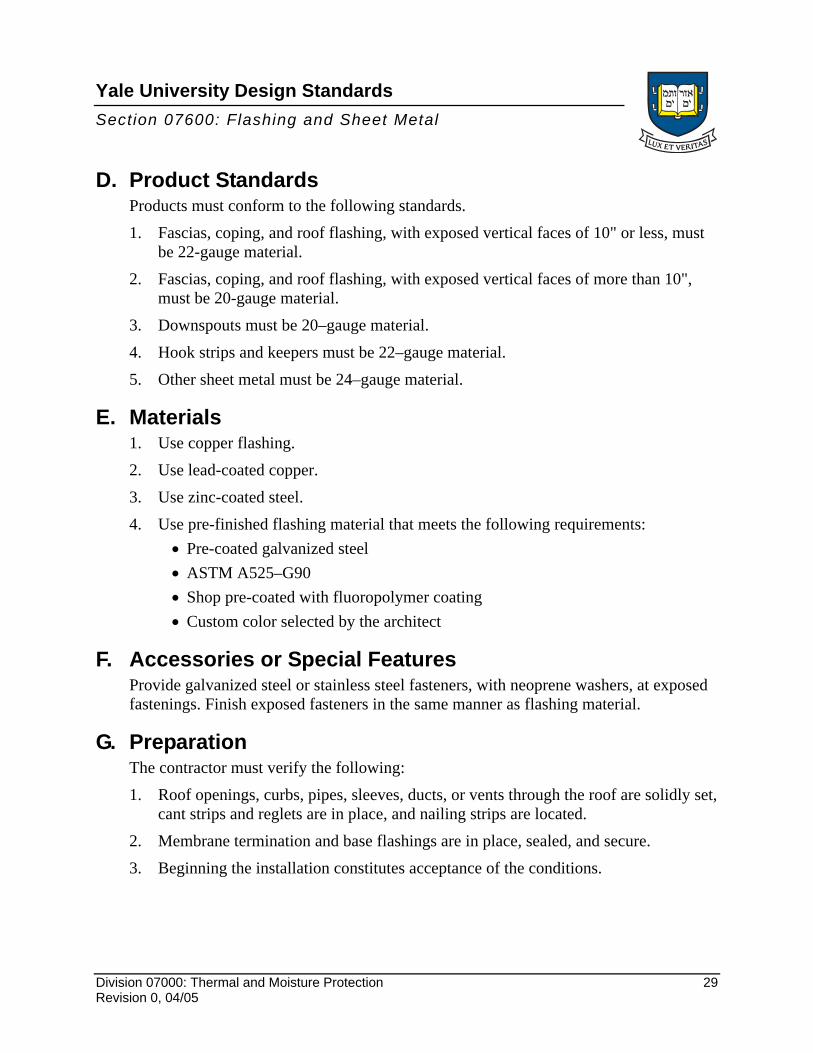
D. Product Standards Products must conform to the following standards. 1. Fascias, coping, and roof flashing, with exposed vertical faces of 10" or less, must
be 22-gauge material. 2. Fascias, coping, and roof flashing, with exposed vertical faces of more than 10",
must be 20-gauge material. 3. Downspouts must be 20–gauge material. 4. Hook strips and keepers must be 22–gauge material. 5. Other sheet metal must be 24–gauge material.
E. Materials 1. Use copper flashing. 2. Use lead-coated copper. 3. Use zinc-coated steel. 4. Use pre-finished flashing material that meets the following requirements:
• Pre-coated galvanized steel • ASTM A525–G90 • Shop pre-coated with fluoropolymer coating • Custom color selected by the architect
F. Accessories or Special Features Provide galvanized steel or stainless steel fasteners, with neoprene washers, at exposed fastenings. Finish exposed fasteners in the same manner as flashing material.
G. Preparation The contractor must verify the following: 1. Roof openings, curbs, pipes, sleeves, ducts, or vents through the roof are solidly set,
cant strips and reglets are in place, and nailing strips are located. 2. Membrane termination and base flashings are in place, sealed, and secure. 3. Beginning the installation constitutes acceptance of the conditions.
Division 07000: Thermal and Moisture Protection 29 Revision 0, 04/05

Yale University Design Standards Section 07600: Flashing and Sheet Metal
H. Installation Guidelines Refer to details included in the SMACNA architectural sheet metal manual.
End of Section
Division 07000: Thermal and Moisture Protection 30 Revision 0, 04/05
Yale University Design Standards
07900 Joint Sealers
This document provides design standards only, and is not intended for use, in whole or in part, as a specification. Do not copy this information verbatim in specifications or in notes on drawings. Refer questions and comments regarding the content and use of this document to the Yale University Project Manager.
CONTENTS A. SummaryB. System Design and Performance RequirementsC. SubmittalsD. Product StandardsE. ManufacturersF. MaterialsG. Accessories or Special FeaturesH. PreparationI. Installation GuidelinesJ. Quality Control
A. Summary This section contains general design criteria for joint sealers.
B. System Design and Performance Requirements Provide sealants at the intersection of building components—or as part of a system—of a type that will seal the joint properly and that is compatible with the materials to be sealed.
C. Submittals Warranties must include the labor and materials required to replace sealants that fail because of loss of cohesion or adhesion, or that fail to cure.
D. Product Standards Interior products must conform to the following standards:
• ASTM C790 – Recommended Practices for Use of Latex Sealing Compounds • ASTM C804 – Recommended Practices for Use of Solvent – Release Type Sealants • ASTM C834 – Latex Sealing Compounds • ASTM C920 – Elastomeric Sealants • ASTM C1193 – Standard Guide for Use of Joint Sealants
Division 07000: Thermal and Moisture Protection 31 Revision 0, 04/05

Yale University Design Standards Section 07900: Joint Sealers
E. Manufacturers Subject to compliance with the design requirements, manufacturers offering products that may be incorporated in the work include, but are not limited to, the following. • Pecora Corporation • Sonneborn Building Products • Tremco • Dow Corning Corporation • General Electric Company • United States Gypsum • EM-Seal Corporation • Illbruck Corporation
F. Materials
Table 1. Sealants
Sealant Description Location Products SLNT-1 Two-component, non-sag,
polyurethane with movement capability of ± 50 per cent. Conforming to ASTM C920, Type M, Grade NS, Class 25 non-staining.
Concrete construction, expansion, and contraction joints. Exterior wall joints and control joints. Perimeter of storefront, door frames, and louvers. Miscellaneous exterior caulking and sealing.
• Pecora Dynatrol II • Sonneborn Sonolastic
NP2 • Tremco Dymeric
SLNT-2 Self-leveling, two component, non-staining, non-bleeding polyurethane with movement capability of ± 25%. Conforming to ASTM C920, Type M, Grade P, Class 25.
Concrete construction, expansion, and contraction joints. Exterior wall joints and control joints. Perimeter of storefront, door frames, and louvers. Miscellaneous exterior caulking and sealing.
• Pecora, Dynatrol II • Sonneborn Sonolastic
NP2 • Tremco Dymeric
SLNT-3 Silicone sanitary sealant, ASTM C920, Type S, Grade NS. Mildew resistant.
Joints between plumbing fixtures and walls. Joints surrounding plastic laminate vanities and counter tops, fixtures, and equipment requiring sanitary sealant.
• Dow 786 mildew resistant silicone sealant
• GE 1700 Sealant • Sonneborn Omniplus
Division 07000: Thermal and Moisture Protection 32 Revision 0, 04/05

Yale University Design Standards Section 07900: Joint Sealers
Table 1. Sealants (Continued)
Sealant Description Location Products SLNT-4 Acoustical sealant; non-
hardening, non-skinning acoustical sealant for concealed joints.
Joints at sound-proofed partitions.
• Tremco acoustical sealant
• USG acoustical sealant
SLNT-5 One part, non-sag, skinning, paintable, acrylic latex sealant capable of ± 7.5% minimum movement.
Miscellaneous interior and exterior joints subject to moderate movement and joints to be painted.
• Pecora AC-20 siliconized • Sonneborn Sonolac • Tremco acrylic latex 834
SLNT-6 Silicone building and glazing sealant, ASTM C920, Type S, Grade NS, Class 25, single component, chemical curing.
Interior and exterior sealing of metal to metal. Installation of glazing.
• Dow Corning 999-A
SLNT-7 Expandable foam sealer. Backer for exterior wide joints subject to dynamic movement.
• EM-Seal Corp Gray-Flex • Illbruck Corp. Will-Seal
Tape, Type 150
G. Accessories or Special Features Provide joint cleaner and bond breakers as required and/or recommended by the sealant manufacturer.
H. Preparation Clean, prepare, and design joints in accordance with the manufacturer's instructions.
I. Installation Guidelines 1. Comply with the sealant manufacturer’s material installation instructions and
requirements for the preparation of surfaces. 2. Verify that the physical and environmental conditions for installation are
acceptable. Beginning the installation constitutes acceptance of the conditions.
J. Quality Control Verify joint dimensions.
End of Section
Division 07000: Thermal and Moisture Protection 33 Revision 0, 04/05


