
07 Mn1780eu09mn 0001 Omsb Overview
23
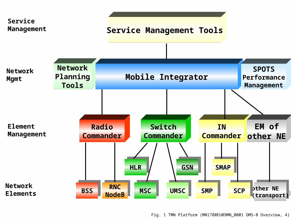
Network Mgmt Element Management Network Elements Service Management HLR other NE (transport) BSS IN Commander Switch Commander Radio Commander EM of other NE RNC NodeB MSC UMSC SMAP SMP SCP Network Planning Tools GSN Service Management Tools Mobile Integrator SPOTS Performance Management Fig. 1 TMN Platform (MN1780EU09MN_0001 OMS-B Overview, 4)
-
Upload
alqousimuhieddine -
Category
Documents
-
view
15 -
download
0
description
afa
Transcript of 07 Mn1780eu09mn 0001 Omsb Overview
NetworkMgmt
ElementManagement
NetworkElements
ServiceManagement
HLRHLR
other NE(transport)
other NE(transport)
BSSBSS
INCommander
SwitchCommander
RadioCommander
EM ofother NE
RNCNodeBRNC
NodeBMSCMSC UMSCUMSC
SMAPSMAP
SMPSMP SCPSCP
NetworkPlanning
Tools
GSNGSN
Service Management Tools
Mobile IntegratorSPOTS
PerformanceManagement
Fig. 1 TMN Platform (MN1780EU09MN_0001 OMS-B Overview, 4)
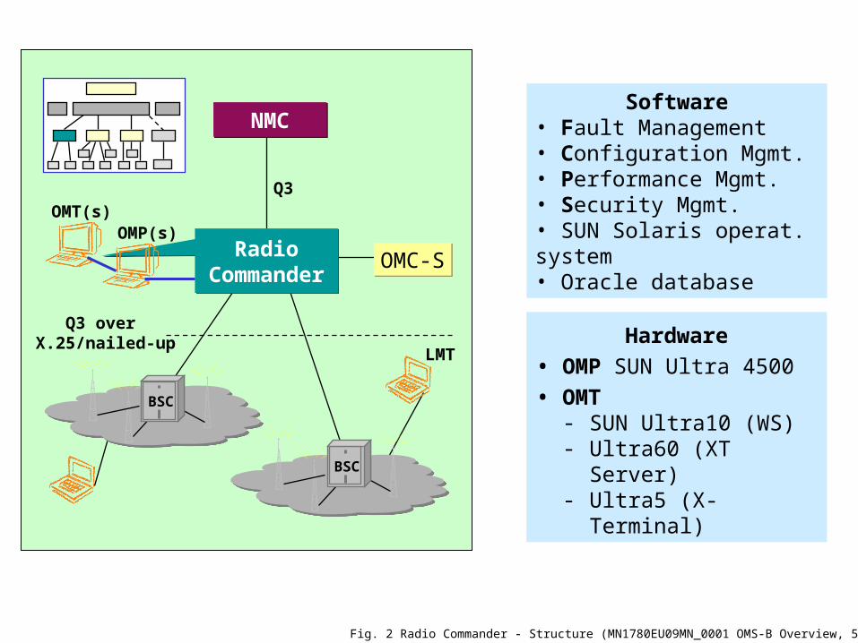
Software• Fault Management• Configuration Mgmt.• Performance Mgmt.• Security Mgmt.• SUN Solaris operat. system• Oracle database
Hardware
• OMP SUN Ultra 4500
• OMT- SUN Ultra10 (WS)- Ultra60 (XT Server)- Ultra5 (X-Terminal)
Q3 over X.25/nailed-up
OMT(s)
LMT
NMCNMC
OMC-SOMC-S
Q3
RadioCommander
RadioCommander
OMP(s)
BSC
BSC
Fig. 2 Radio Commander - Structure (MN1780EU09MN_0001 OMS-B Overview, 5)

Fig. 3 Radio Commander Basic and Application Packages (MN1780EU09MN_0001 OMS-B Overview, 5)

Ultra 10Ultra 10
OMT (2 sessions)
Ultra 60
OMT Server
Ultra 5Ultra 5
Minimum OMT (1 session)
Ultra 1 / 200EUltra 1 / 200E
X Terminal
Ultra 1 / 140EUltra 1 / 140E Ultra 1 / 170EUltra 1 / 170E
Fig. 4 OMT / Xterminal supported (MN1780EU09MN_0001 OMS-B Overview, 7)
Ultra 10Ultra 10
E4500 / E4000E4500 / E4000
E420RE420R
Ultra5Ultra5
MSC
BSC
BSC
X Terminal X Terminal
CLI telnet access
CLI modemaccess
remote OMT remote OMT
X TerminalServer
X.25
LANDedicated
X.25
PCM30/24 "nailed-up"
connection
Hub
OMTOMTLAN
OMP
X.25 net
Modem
BSC
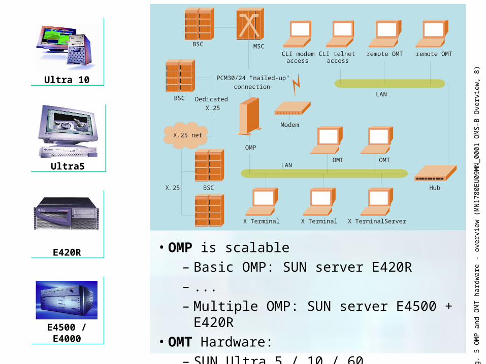
• OMP is scalable– Basic OMP: SUN server E420R– ...– Multiple OMP: SUN server E4500 + E420R
• OMT Hardware:– SUN Ultra 5 / 10 / 60 F
ig. 5
OM
P a
nd O
MT
har
dwar
e -
over
view
(M
N17
80E
U09
MN
_000
1 O
MS
-B O
verv
iew
, 8)

Sun Blade 1000Sun Blade 1000
LAN (10/100BaseT)
OMT OMT
OMP
O&M ToolSet ServerO&M ToolSet Server
OMT
MultiPackMultiPack
OMT
Fig. 6 O & M tool set (MN1780EU09MN_0001 OMS-B Overview, 8)
Sun Server
Enterprise 4500
Sun Server
Enterprise 4500
LAN (Fast Ethernet 10/100BaseT)
Console
OMT
Colour Spoolprinter
OMT
Spoolprinter b&w
NE‘sNE‘s
DiskArrayDiskArray
Alarm Printer
DiskArrayDiskArray
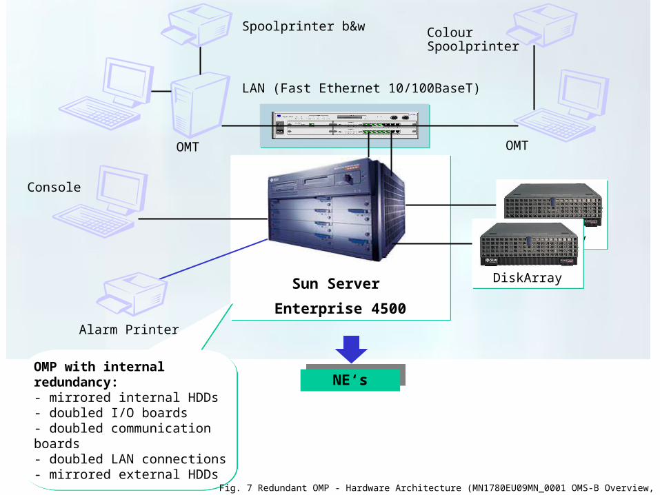
OMP with internal redundancy:- mirrored internal HDDs- doubled I/O boards- doubled communication boards- doubled LAN connections- mirrored external HDDs
OMP with internal redundancy:- mirrored internal HDDs- doubled I/O boards- doubled communication boards- doubled LAN connections- mirrored external HDDs
Fig. 7 Redundant OMP - Hardware Architecture (MN1780EU09MN_0001 OMS-B Overview, 9)

NE‘sNE‘s
Sun Server
Enterprise 4500
Sun Server
Enterprise 4500
Sun Server
Enterprise 420R
Sun Server
Enterprise 420R
Console
LAN (Fast Ethernet 10/100BaseT)
Primary ServerPrimary Server Secondary ServerSecondary Server
Colour Spoolprinter
OMTOMT
Spoolprinter b&w
DiskArrayDiskArray
Alarm Printer
NE‘sNE‘s
Multiple OMP: Logical OMC with transparent access to common database from every OMT
Fig. 8 Multiple OMP - Hardware Architecture (MN1780EU09MN_0001 OMS-B Overview, 9)
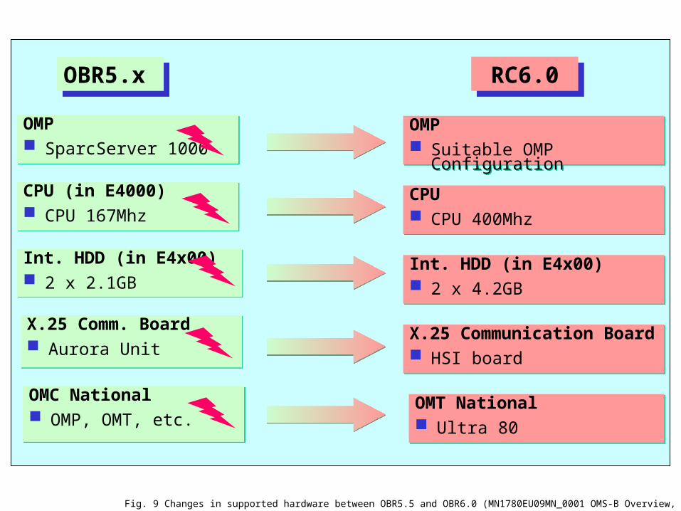
OMP SparcServer 1000
OMP SparcServer 1000
OBR5.xOBR5.x RC6.0RC6.0
CPU (in E4000) CPU 167Mhz
CPU (in E4000) CPU 167Mhz
Int. HDD (in E4x00) 2 x 2.1GB
Int. HDD (in E4x00) 2 x 2.1GB
X.25 Comm. Board Aurora Unit
X.25 Comm. Board Aurora Unit
OMC National OMP, OMT, etc.
OMC National OMP, OMT, etc.
OMP Suitable OMP Configuration
OMP Suitable OMP Configuration
CPU CPU 400Mhz
CPU CPU 400Mhz
Int. HDD (in E4x00) 2 x 4.2GB
Int. HDD (in E4x00) 2 x 4.2GB
X.25 Communication Board HSI board
X.25 Communication Board HSI board
OMT National Ultra 80
OMT National Ultra 80
Fig. 9 Changes in supported hardware between OBR5.5 and OBR6.0 (MN1780EU09MN_0001 OMS-B Overview, 10)

OMP (E4x00):
2 x CPU 250Mhz
2 x CPU 400Mhz
512MB RAM
OMP (E4x00):
2 x CPU 250Mhz
2 x CPU 400Mhz
512MB RAM
OMP (E4x00)
4 x CPU 250Mhz
4 x CPU 400Mhz
4 GB RAM
OMP (E4x00)
4 x CPU 250Mhz
4 x CPU 400Mhz
4 GB RAM
OBR5.xOBR5.x RC6.0RC6.0
Single OMP (E4x00):
1 existing E4x00
Single OMP (E4x00):
1 existing E4x00
Multiple OMP:
additional E420R / E4500
Multiple OMP:
additional E420R / E4500
External Harddisks:
Multipack (54 GB / 109GB)
External Harddisks:
Multipack (54 GB / 109GB)
External Harddisks:
DiskArray D1000 (145 GB / 218 GB / 436 GB)
External Harddisks:
DiskArray D1000 (145 GB / 218 GB / 436 GB)
Backup&Restore (opt. Feature):
DDS3 Autoloader
Backup&Restore (opt. Feature):
DDS3 Autoloader
Backup&Restore (opt. Feature):
DLT Autoloader L9
Backup&Restore (opt. Feature):
DLT Autoloader L9
Mandatory
Optional
Fig. 10 Hardware upgrade between OBR5.x and OBR6.0 (mandatory above, optional - depending on the number of TRX / BSC, below) (MN1780EU09MN_0001 OMS-B Overview, 10)
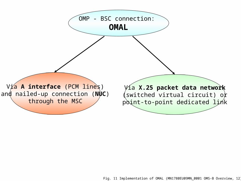
OMP - BSC connection:
OMAL
Via A interface (PCM lines)and nailed-up connection (NUC)
through the MSC
Via X.25 packet data network(switched virtual circuit) or
point-to-point dedicated link
Fig. 11 Implementation of OMAL (MN1780EU09MN_0001 OMS-B Overview, 12)

PCMS
BSC
IXLT
SYNCHRO
TS 30
OMAL
TRAUMSC
Semi permanent or nailed up
connection (64 kbit/s)
X25A
Newbridge Sprite E1
OMP
Fig. 12 Interface card Newbridge sprite E1 (back view) (MN1780EU09MN_0001 OMS-B Overview, 12)

BSC
IXLT
OMC
HSI/PCI
PSDNX.25 network
Modem Modem
dedicated point to point connection
connection via a packet switched data network
X.21/ V.11 Interface
Fig. 13 Two options for implementing a dedicated line (MN1780EU09MN_0001 OMS-B Overview, 13)

Operation and Maintenance Processor OMP
X.25 Packet Data Network PDN
Newbridge Sprite E1
AURORA
HSI / PCI Board
MSC
TRAU
BSC BSC BSC
PCM Link E1 / T1max 31 /24 TS(each 64 kbit/s)
48 Links X.25(each 64 kbit/s)
4 Links X.25(each 2 Mbit/s)
Nailed-Up Connection(64 kbit/s)
X.25 Connection (64 kbit/s)
Not for OBR6.0
Fig. 14 Realization of OMAL (i/f between OMC-B and SBS) (MN1780EU09MN_0001 OMS-B Overview, 13)
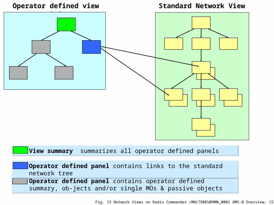
Standard Network ViewOperator defined view ‘n’
Operator defined panel contains operator defined summary, ob-jects and/or single MOs & passive objectsOperator defined panel contains operator defined summary, ob-jects and/or single MOs & passive objects
Operator defined panel contains links to the standard network treeOperator defined panel contains links to the standard network tree
View summary summarizes all operator defined panelsView summary summarizes all operator defined panels
Fig. 15 Network Views on Radio Commander (MN1780EU09MN_0001 OMS-B Overview, 15)

Fig. 16 Application Launcher (MN1780EU09MN_0001 OMS-B Overview, 16)

Fig
. 17
Geo
grap
hica
l Map
(M
N17
80E
U09
MN
_000
1 O
MS
-B O
verv
iew
, 16)

Fig. 18 BTSone Panel with Logical Icons and Rack Layout (lower left), BSS Region Panel with Help View for State Attributes (upper right) (MN1780EU09MN_0001 OMS-B Overview, 17)

Fig. 19 Operation and Maintenance Tool Set (MN1780EU09MN_0001 OMS-B Overview, 19)

Fig. 20 Pop-Up Menu on LMT Input Handler (MN1780EU09MN_0001 OMS-B Overview, 22)

Fig. 21 LMT Input Handler with Command Viewer (MN1780EU09MN_0001 OMS-B Overview, 22)
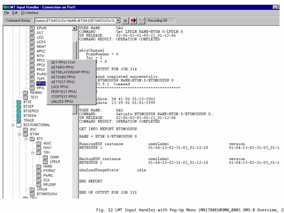
Fig. 22 LMT Input Handler with Pop-Up Menu (MN1780EU09MN_0001 OMS-B Overview, 23)
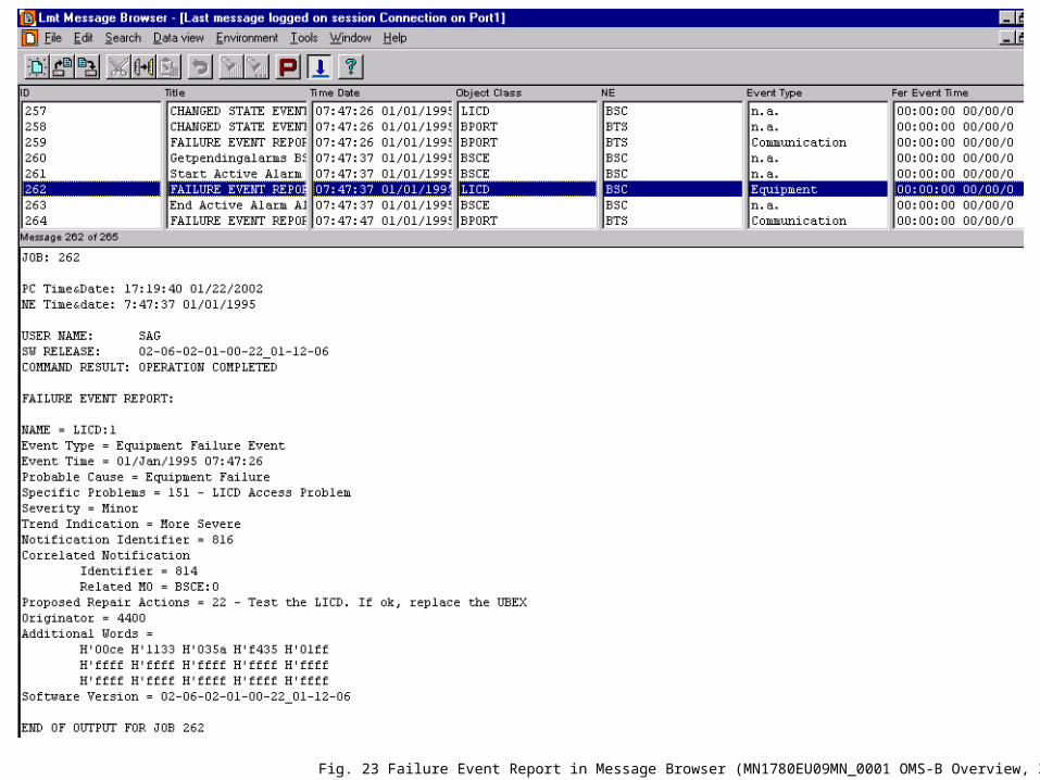
Fig. 23 Failure Event Report in Message Browser (MN1780EU09MN_0001 OMS-B Overview, 23)