06/09/2004 - Techmeta
7
EBW process is a welding process by fusion using the kinetic energy conversion of the electrons into thermal energy when they enter in collision with the part to be welded. Two machined parts are put together edge to edge; the electron beam melt the interface and forms a very narrow bead with almost parallel edges and limited deformations. Electron Beam is produced by an EB gun operating under vacuum. The electrons are extracted from a cathode, heated up to emission temperature. They are accelerated by high voltage between cathode and anode. SEMINAIRE FRANCO-SUEDOIS 6-7/09/04 “NEW APPLICATIONS OF ELECTRON BEAM WELDING TO VERY LARGE PRECISION PARTS AND INDUSTRIAL PROSPECTS” We will briefly introduce some basic principles of Electron Beam Welding technology before presenting two significant application to very large parts in main international projects, and conclude by examples of more usual industrial applications and equipment. 1. PRINCIPLES OF ELECTRONS BEAM WELDING (EBW) Fig. 1 : Principles of Electron beam welding 1.1. PRINCIPLE OF ELECTRON BEAM GUN 2. INTRODUCTION TO ARIANE V EVOLUTION PROJECT After qualification flight during year 1999 , ARIANE V launcher is able to transport 6.8 tons payload into geostationnary transfer orbit in dual-launch mode. Each booster case, total length 25m and diameter 3 m roughly, is composed of 3 segments : - The Forward segment S1 consists of a front dome and a short cylinder - The central segment S2 consists of 3 cylinders each 3.4 m in length - The rear segment consists of 3 cylinders each 3.4 m in length + a dome with a flange for the nozzle cone
Transcript of 06/09/2004 - Techmeta

EBW process is a welding process by fusionusing the kinetic energy conversion of the electrons intothermal energy when they enter in collision with the partto be welded.
Two machined parts are put together edge toedge; the electron beam melt the interface and forms avery narrow bead with almost parallel edges and limiteddeformations.
Electron Beam is produced by an EB gun operating undervacuum.
The electrons are extracted from a cathode,heated up to emission temperature.
They are accelerated by high voltage betweencathode and anode.
SEMINAIRE FRANCO-SUEDOIS 6-7/09/04
“NEW APPLICATIONS OF ELECTRON BEAM WELDING TO VERY LARGEPRECISION PARTS AND INDUSTRIAL PROSPECTS”
We will briefly introduce some basic principles of Electron Beam Welding technology before presenting twosignificant application to very large parts in main international projects, and conclude by examples of more usualindustrial applications and equipment.
1. PRINCIPLES OF ELECTRONS BEAM WELDING (EBW)
Fig. 1 : Principles of Electron beam welding
1.1. PRINCIPLE OF ELECTRON BEAM GUN
2. INTRODUCTION TO ARIANE V EVOLUTION PROJECT
After qualification flight during year 1999 , ARIANE V launcher is able to transport 6.8 tons payload intogeostationnary transfer orbit in dual-launch mode.Each booster case, total length 25m and diameter 3 m roughly, is composed of 3 segments : - The Forward segment S1 consists of a front dome and a short cylinder
- The central segment S2 consists of 3 cylinders each 3.4 m in length - The rear segment consists of 3 cylinders each 3.4 m in length + a dome with a flange for the nozzle cone
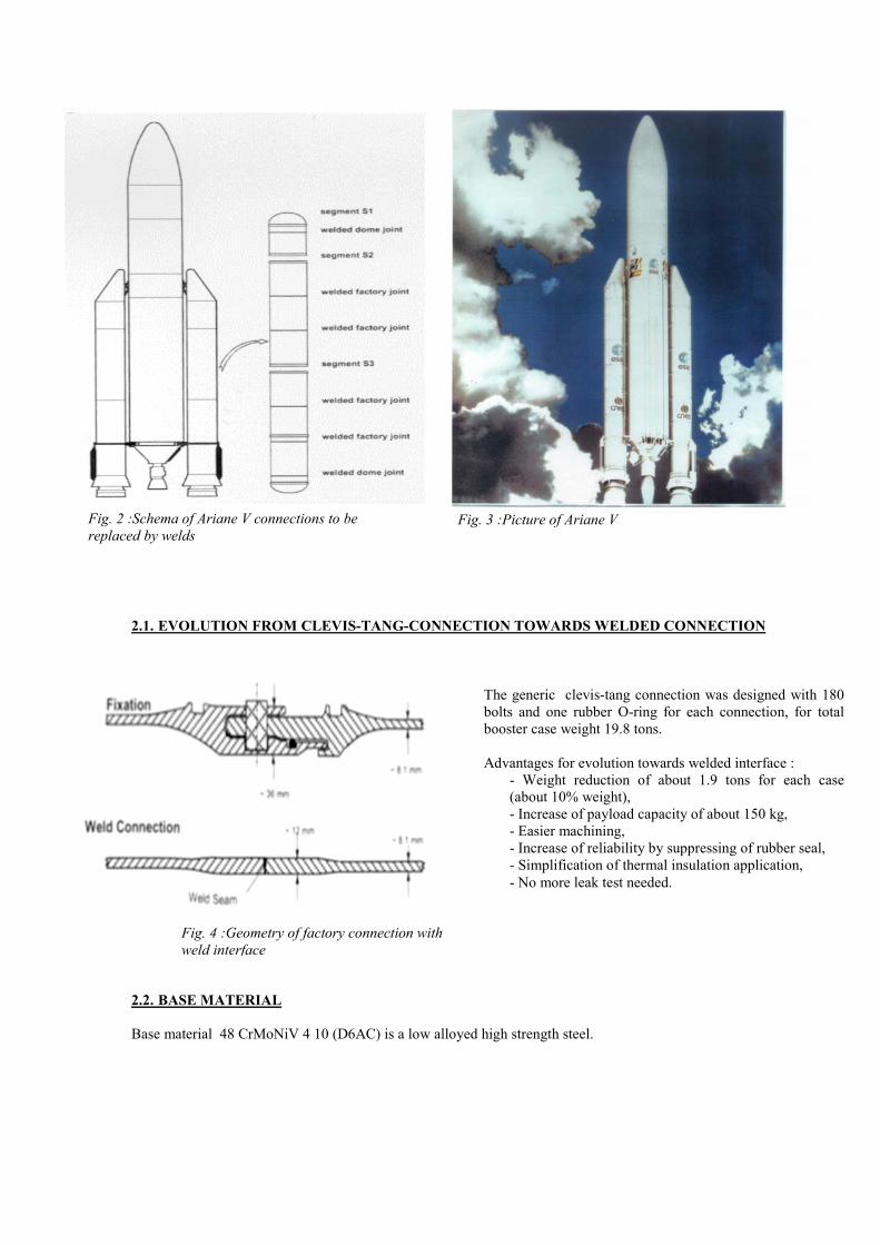
Fig. 3 :Picture of Ariane V
Fig. 2 :Schema of Ariane V connections to bereplaced by welds2.1. EVOLUTION FROM CLEVIS-TANG-CONNECTION TOWARDS WELDED CONNECTION
2.2. BA
Base m
The generic clevis-tang connection was designed with 180bolts and one rubber O-ring for each connection, for totalbooster case weight 19.8 tons.
Advantages for evolution towards welded interface :- Weight reduction of about 1.9 tons for each case(about 10% weight),- Increase of payload capacity of about 150 kg,- Easier machining,- Increase of reliability by suppressing of rubber seal,- Simplification of thermal insulation application,- No more leak test needed.
Fig. 4 :Geometry of factory connection withweld interface
SE MATERIAL
aterial 48 CrMoNiV 4 10 (D6AC) is a low alloyed high strength steel.

Dedman
Fig. 5 :Characteristics of base material
Fig. 6 :Cross-section of TECHMETA"hypermachine" in Augsburg-Diameter 5000 mm Height 15000 mm-
Fig. 7 :Picture of electron beam welding"hypermachine" for large rocket booster cases(during installation)
2.3. WELDING
In a basic investigation program :- TIG welding,- A-TIG welding (with activating powder for deep penetration),- Laser welding,- Electron Beam welding.
Have been checked for applicability.With respect to the weld material properties, performance of the welding process and investments for serialproduction, the Electron Beam (EB)-welding in full vacuum chamber has been selected.
2.4. WELDING EQUIPMENT
A
icated huge welding machine was designed andufactured by TECHMETA company in France.This equipment has been delivered and fully tested at MAN TECHNOLOGY in Augsburg / Germanyduring year 2002.The machine is schematically composed of following main elements� Fixed base with all functional systems :� External movable EB gun 20 kW/70kV,� Vertical Internal carriage with EB gun 20kW/70kV,� X Ray inspection system 4 KW/160kV,� Pumping system with primary and secondary vacuum.

� Vacuum chamber modular elements :Those elements can be adapted in height to the height of the part,on each step of the works.
� Internal high precision clamping tooling system for positioning the parts in expanded position� Handling system for displacement and stocking of the modular elements� CNC system with data recording system
2.5. WELDING PROCEDURE
During welding the single parts are aligned with their verticalaxes and fixed from inside by a clamping tool.Following procedure has been selected :
a-From the outside : - Discontinuous tacking pass (12x),- Continuous tacking pass,- Fusion pass and cosmetic pass onthe face side.
b-From the inside : - Cosmetic pass on the root side.- X Ray inspection withoutremoving the part.- Tempering with a local heattreating equipment of about 40 mn.
2.6. QUALIFICATION STEPS
During qualification procedure, integral tensile test samples of sizeThe rupture of the most of these samples was in the base material fBecause the stress distribution of a tensile sample is different to thaqualification concept has been developed first in sub-scale burst te
2.7. SERIAL QUALITY CONTROL
Welded Samples In the series production, 3 different types of samples have to be wereproducibly as possible.
Data RecordingThe data recording system of the machine can record in a high freqparameters :
- Beam current,- Beam voltage,- Welding speed,- Focus current,- Vacuum level in chamber,
Fig. 8 :Macrograph of the weld cross-section
12 x 40 mm have been tested. ar away from the weld.t in a pressure vessel, a furthersts, and then in full scale.
Fig. 9 :Ruptured integral tensile testsample / cross-section 12x40 mm
Fig. 10 :Full-scale pressure vessel Model Q
lded to guarantee the weld quality as
uency during welding following
- Vacuum level in operating gun,- Position of the rotating table.
2.8. REPAIR PROCEDURE
For welding cost-intensive work pieces, a qualified repair procedure is absolutely required.� EB and TIG process have been qualified for repairing.� The full production process has been qualified for starting serial production of EB welded booster
cases.
2.9. THE MANUFACTURING OF EB WELDED BOOSTER CASES HAS BEEN QUALIFIED ANDTHE EQUIPMENT IS READY FOR STARTING INDUSTRIAL PRODUCTION
3. CONTINUOUS REINFORCEMENT OF SUPER-CONDUCTOR FOR THE "CMS" EXPERIMENTAT CERN LAB IN GENEVE
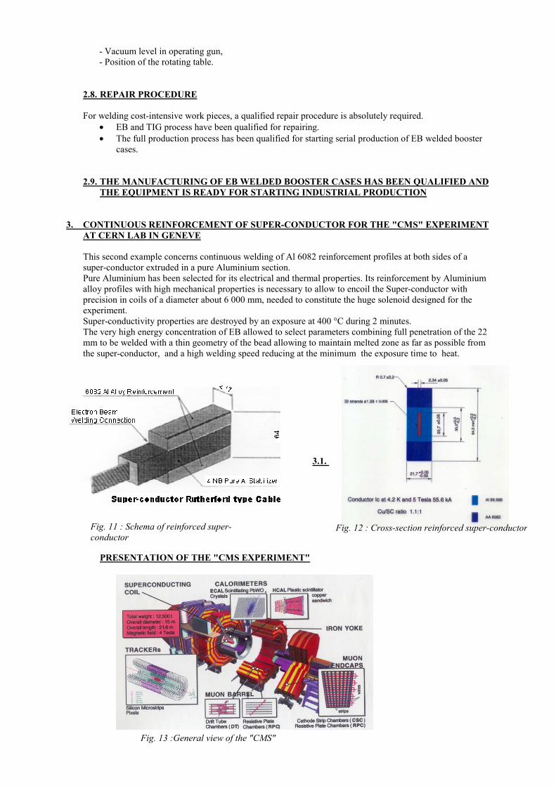
This second example concerns continuous welding of Al 6082 reinforcement profiles at both sides of asuper-conductor extruded in a pure Aluminium section. Pure Aluminium has been selected for its electrical and thermal properties. Its reinforcement by Aluminiumalloy profiles with high mechanical properties is necessary to allow to encoil the Super-conductor withprecision in coils of a diameter about 6 000 mm, needed to constitute the huge solenoid designed for theexperiment. Super-conductivity properties are destroyed by an exposure at 400 °C during 2 minutes.The very high energy concentration of EB allowed to select parameters combining full penetration of the 22mm to be welded with a thin geometry of the bead allowing to maintain melted zone as far as possible fromthe super-conductor, and a high welding speed reducing at the minimum the exposure time to heat.
3.1.
Fig. 11 : Schema of reinforced super-conductor
PRESENTATION OF THE "CMS EXPERIMENT"
Fig. 12 : Cross-section reinforced super-conductor
Fig. 13 :General view of the "CMS"

The “CMS” experiment will take place in the new ring installed at 80 meter depth underground at the French-Swiss border in Geneva, in view to verify the existence of particles named “Muons” according to theoreticalcalculation.
3.2. WELDING EQUIPMENT
Since more than 30 years, TECHMETA developed air-vacuum-air EB welding lines for differentapplications in multi-metallic strips. Based on this experience, a new world single equipment was designedand manufactured for CERN account, and the 52 km continuous welded assembly of super-conductor wasachieved at TECHMETA workshop.
The machine is schematically composed of following main elements:- Pay-off station for the 3 basic profiles- Uncambering/planning units- Cleaning system- Continuous air-vacuum-air EB welding unit- Cooling system- Ultra Sonic inspection unit- 4 faces Machining unit- Cleaning unit- Laser dimensional inspection unit- Driving unit- Encoiler
4.
TheFigu
Fig. 14 :Schema of the 60000 mm length air-vaccum-Air EB welding line
3.3. PRODUCTION OF 52 km SUPER-CONDUCTOR
During year 2002/2003, the whole needed length of 52 km reinforced Super-Conductor was manufactured,on line and off line inspected, and delivered to Italy for encoiling in final magnetic coil to be installed in theinternational CERN LAB in GENEVE.
MORE USUAL INDUSTRIAL APPLICATIONS
se two huge projects are spectacular aspects of the EB technology that is applied in various industrial fields.res 16 to 18 are showing some examples of bead shapes and EB welded industrial parts.

Figures 19 to 21 are showing some types of usual EBW machines.
SINGLE PASS EB WELDING
Fig. 15 : 200 mm in Aluminim
5. CONCLUSIO
The two projects arein huge internationaDesign offices of thlaboratories, are moTitanium or AluminEB technology can in protected surrounhigh level Quality A
By courtesy of MANdetails please refer Berlin-Schönefeld o"Schweißen und LötBy courtesy of CER“Bindungsprüfung aGenève.)
Fig. 16 : 110 mm in Steel
N
showing the progress authorisedl programs.e industries dedicated to defence, re and more confronted with the nium Alloys, high strength steel, rebring an industrial solution combdings under vacuum. The fully aussurance procedures and further s
TECNOLOGY for information anto “Welding and brazing in Aerosn 12th and 14th May 2004 , genehmen im Luft- und RaumfahrzeugbauN for information and figures conn elektronenstrahlgeschweissten
Fig. 17 : Copper part( Electrical connection)
by application of EB technology to v
automotive, space, aeronautics, as weed to manufacture precision parts infractory metals, etc…
ining high energetic performances wtomated process allows full data rectatistical analysis.
d figures concerning ARIANE V boopace Industry” Vorträge des Internaigte Übersetzung aus dem DVS-Ber" des DVS-Verlages, Düsseldorf).
cerning CERN project. ( fore more dHochstrom-Supraleiterkabeln” CER
Fig. 18 : Cross-sectionreinforced super-conductor
EB WELDED INDUCTRIALPART
Fig. 19 :Medium sizeuniversal EBW machine
Fig. 21 :Double gun high productivityEBW machine for automotive parts
ery large components
ell as research specific alloys as
ith almost no distortionording to establish
ster cases (for moretionalen Symposium inichte Band 229
etails, please refer toN publication
Fig. 20 :Small size universalEBW machine