0.5 Watt E-Band Power Combining Amplifier for ...
26
Naval Information Warfare Center Pacific (NIWC Pacific) San Diego, CA 92152-5001 TECHNICAL DOCUMENT 3399 JULY 2020 0.5 Watt E-Band Power Combining Amplifier for Nanosatellite Applications Jia-Chi S. Chieh NIWC Pacific DISTRIBUTION STATEMENT A: Approved for public release.
Transcript of 0.5 Watt E-Band Power Combining Amplifier for ...

Naval Information Warfare Center Pacific (NIWC Pacific) San Diego, CA 92152-5001
TECHNICAL DOCUMENT 3399 JULY 2020
0.5 Watt E-Band Power Combining Amplifier for Nanosatellite Applications
Jia-Chi S. Chieh NIWC Pacific
DISTRIBUTION STATEMENT A: Approved for public release.

This page is intentionally blank.

NIWC Pacific San Diego, CA 92152-5001
TECHNICAL DOCUMENT 3399 JULY 2020
0.5 Watt E-Band Power Combining Amplifier for Nanosatellite Applications
Jia-Chi S. Chieh NIWC Pacific
DISTRIBUTION STATEMENT A: Approved for public release.
Administrative Notes: This document was approved through the Release of Scientific and Technical Information (RSTI) process in November 2019 and formally published in the Defense Technical Information Center (DTIC) in July 2020.

NIWC Pacific San Diego, California 92152-5001
A.D. Gainer, CAPT, USN Commanding Officer
W. R. Bonwit Executive Director
ADMINISTRATIVE INFORMATION The work described in this report was performed by the Advanced Integrated Circuit Technology
Branch (55250) of the Naval Information Warfare Center Pacific (NIWC Pacific), San Diego, CA.
ACKNOWLEDGMENTS
The Office of Naval Research (ONR) provided funding for this 6.2 Discovery and Innovation (D&I) project. The author thanks Dr. Santanu Das for his support.
.
This is a work of the United States Government and therefore is not copyrighted. This work may be copied and disseminated without restriction.
The citation of trade names and names of manufacturers is not to be construed as official government endorsement or approval of commercial products or services referenced in this report.
Released by Phillip Juarez, Division Head Communications Division
Under authority of Susie Hartzog, Department Head Communications and Networking Department
MRM
v
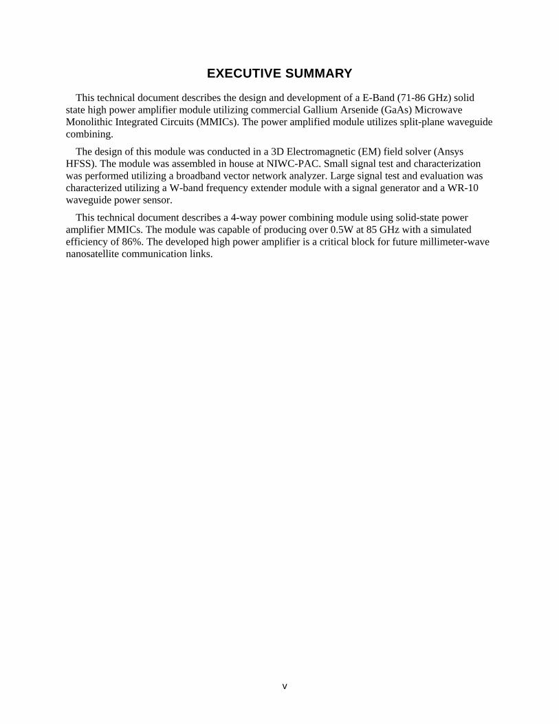
EXECUTIVE SUMMARY
This technical document describes the design and development of a E-Band (71-86 GHz) solid state high power amplifier module utilizing commercial Gallium Arsenide (GaAs) Microwave Monolithic Integrated Circuits (MMICs). The power amplified module utilizes split-plane waveguide combining.
The design of this module was conducted in a 3D Electromagnetic (EM) field solver (Ansys HFSS). The module was assembled in house at NIWC-PAC. Small signal test and characterization was performed utilizing a broadband vector network analyzer. Large signal test and evaluation was characterized utilizing a W-band frequency extender module with a signal generator and a WR-10 waveguide power sensor.
This technical document describes a 4-way power combining module using solid-state power amplifier MMICs. The module was capable of producing over 0.5W at 85 GHz with a simulated efficiency of 86%. The developed high power amplifier is a critical block for future millimeter-wave nanosatellite communication links.

This page is intentionally blank.

ACRONYMS
ASI Italian Space Agency DAVID Data and Video Interactive Distribution dB Decibels dBi Decibels relative to isotropic dBm Decibel milliwatts EIRP Equivalent Isotropic Radiated Power GaAs Gallium Arsenide GHz Gigahertz GEO Geosynchronous Orbit HFSS High Frequency Structure Simulator HPA High Power Amplifier IMPATT Impact Ionization Avalanche Transit Time Diode IKNOW In-Orbit Key Test and Validation of W-Band LEO Low Earth Orbit MACOM Microwave Associates Company MMIC Microwave Module Utilizes Commercial PCB Printed Circuit Boards SATCOM Satellite Communications S-Parameter Scattering Parameers SSPA Solid State High Power Amplifier

This page is intentionally blank.

ix
CONTENTS
EXECUTIVE SUMMARY ........................................................................................................ v ACRONYMS ......................................................................................................................... vii 1. INTRODUCTION .............................................................................................................. 1
1.1 PURPOSE ................................................................................................................ 1 2. STRIPLINE TO WAVEGUIDE DESIGN ........................................................................... 3 3. POWER AMPLIFIER MODULE ....................................................................................... 7 REFERENCES ....................................................................................................................... 9
Figures
1. Suspended stripline to waveguide transition. .................................................................. 2
2. Simulation result of WR-10 to suspended stripline transition .......................................... 4
3. Full HFSS simulation model. ........................................................................................... 4
4. Simulated full back-to-back structure in HFSS. ............................................................... 5
5. Fabricated prototype showing full MMIC assembly. ........................................................ 5
6. Measured S-parameters of 4-way HPA. .......................................................................... 6
7. Optical and infrared images of HPA module under bias. ................................................ 7
8. Large signal test bench. .................................................................................................. 7
9. Large signal compression testing. ................................................................................... 8

This page is intentionally blank.

1
1. INTRODUCTION
1.1 PURPOSE Millimeter wave communication links are increasingly becoming more and more important as the
thirst for bandwidth increases. This is especially true for environments that don’t lend itself for fiber-optic infrastructure, such as rural areas or densely populated areas where laying fiber can be disruptive. In the last decade, E-Band (71-86 GHz) has become a viable option for high bandwidth line of sight communications. They are used by telecommunication companies for mobile backhaul [1]. They are also utilized for low latency rapid stock trading between various physically disparate markets [2]. More recently, W/E/V-Band has been proposed for Satellite Communications (SATCOM) both for Low Earth Orbit (LEO) [3] and for Geosynchronous Orbit (GEO) [4].
In the early 2000s, the Italian space agency (ASI) launched DAVID (Data and Video Interactive Distribution), a LEO mission to investigate propagation effects at W-Band [3]. A subsequent mission IKNOW (in-orbit key-test and validation of W-Band) was launched for follow-on experimentation [5]. The IKNOW mission utilized a cost effective nanosatellite platform. SATCOM on a nanosatellite platform is challenging as there are many limitations, two are size and power. Size limits the antenna gain which is possible; power limits the output power of the transmitter. A 6U nanosatellite space craft has a total size of 30 cm x 20 cm x 10 cm, with an power capability of 72W [6]. Link budget calculations from DAVID and IKNOW indicate an EIRP of 57 dBm at 82 GHz and 50 dBm at 84 GHz is needed to close the link. In both missions, Cassegrain antennas with over 40 dB of gain were necessary because lower output power IMPATT amplifiers (200mW) were used. Large antennas require complex payloads which unfurl. Solid-state HPAs offers the benefit of high output powers, which is preferable because it trades antenna size with power.
Work has been done to develop power combining SSPA including septum based waveguide combiners [7] and radial waveguide combiners [8]. At millimeter wave frequencies, transmission line losses can be quite large. The mitigation of losses equals higher combining efficiencies, which is critical to “macro” level power combining amplifiers. In order to reduce loss, a suspended stripline to rectangular waveguide transition is utilized. Our designed SSPA is designed to complete a downlink from LEO given a 37 dBi antenna (half the aperture of a 40 dBi antenna, and can fit in a 1U volume). The designed 4-way SSPA module has a measured 3-dB bandwidth of 22 GHz from 67 to 89 GHz, with a measured output power of at least 0.5 Watts at 85 GHz. The 4-way combiner has a simulated efficiency of 86%. To the author’s knowledge, this is the highest reported output power at E-Band for a power combining module using GaAs MMICs. Figure 1 displays suspended stripline to waveguide transition. Figure 1 (a) shows the Top Level view of the stripline to waveguide WR-10 transition, and Figure 1 (b) shows a side view cross section of the stripline to waveguide transition.

2
(a) Top down view (b) Cross-section view (all dimensions in mils)
Figure 1. Suspended stripline to waveguide transition.

3
2. STRIPLINE TO WAVEGUIDE DESIGN
Waveguide combining power amplifiers typically utilize what’s known as a microstrip E-plane probe in order to couple power from the waveguide to a MMIC [8]. Suspended stripline is preferable because most of the propagation energy is in the air dielectric, and the support substrate generally has a negligible impact on the attenuation and phase delay of the stripline. The stripline E-plane probes are designed on a 5-mil Fused Silica substrate (ɛr ~3.8, δ ~ 0.0002). As can be seen, the transition is designed such that the waveguide back short is rounded, with a 25 mil radius, as to allow for easy machining with an end-mill. The Fused Silica substrate straddles a channel on the lower half of the split-block. Small metal ledges form support structure for the substrate, and in this way, the substrate can be fully suspended. Figure 2 shows the simulated response of the waveguide to suspended stripline transition in HFSS. As can be seen, the impedance matching of the transition is broadband, with a 10 dB impedance bandwidth of in excess of 40 GHz. The simulated insertion loss is 0.36 dB maximum from 71-86 GHz.
Figure 3 shows a back-to-back model in HFSS for the full passive module, including waveguide to suspsended stripline transition, and suspended stripline to MMIC bond wire transition. The model included a passive GaAs microstrip through line, that was de-embedded from the loss simulation. A 10mil Eccosorb® BSR absorber was used in the cavities to prevent oscillation. In simulation, a 377 Ω impedance boundary was used to model the microwave absorber. Figure 4 shows the simulated results from the back-to-back model, showing better than 10 dB S11 from 71-100 GHz, with an average insertion loss of 0.65 dB, which equates to an average efficiency of 86%. Fabricated prototype is shown in Figure 5. S-parameter measurements were made on an Anritsu ME7808A vector network analyzer using a waveguide TRM (Thru-Reflect-Match) calibration kit. The amplifier was measured with gate biased to -0.2 V and drain biased at 3.5 V, with the whole amplifier module drawing 3.45A. The measured s-parameter results are shown in Figure 6, as can be seen, the amplifier module has similar gain characteristic as the individual generator, MMIC. The minimum gain of the module occurs at 80 GHz, with a gain of 18 dB. The main reason why the gain is lower than nominal on the datasheet is because of temperature.

4
Figure 2. Simulation result of WR-10 to suspended stripline transition
Figure 3. Full HFSS simulation model.
-1
-0.9
-0.8
-0.7
-0.6
-0.5
-0.4
-0.3
-0.2
-0.1
0
-45
-40
-35
-30
-25
-20
-15
-10
-5
0
60 70 80 90 100 110
S21
(dB)
S11
(dB)
Frequency (GHz)
S11 S21

5
Figure 4. Simulated full back-to-back structure in HFSS.
Figure 5. Fabricated prototype showing full MMIC assembly.
-18
-16
-14
-12
-10
-8
-6
-4
-2
0
-40
-35
-30
-25
-20
-15
-10
-5
0
60 70 80 90 100 110
S21 (
dB)
S11 (
dB)
Frequency (GHz)
S11 S21

6
Figure 6. Measured S-parameters of 4-way HPA.
-60
-50
-40
-30
-20
-10
0
10
20
30
65 70 75 80 85 90 95 100 105 110
S-Pa
ram
eter
s (dB
)
Frequency (GHz)
S11 S12 S21 S22

7
3. POWER AMPLIFIER MODULE
A 4-way power combined amplifier module was designed and fabricated utilizing the waveguide transition from Section II. Commercial HPA MMICs from MACOM were used (MAAP-011106) [14]. The commercial MMIC has a Psat of 25 dBm, a P1dB of 23 dBm, and a gain of between 18 – 20 dB, and operates from 71 – 86 GHz. E-Plane Y-junction waveguide power dividers/combiner were utilized for the 4-way module. Each of the Y-Junctions had a 3 section impedance transformer, using design procedure from [13] to allow for ultra-wideband operation. 2 sets of printed circuit boards (PCBs) were used for each MMIC, one providing gate bias for each of the 4-stage amplifier with inline 10 Ω resistors for stability, one providing drain bias for each of the 4-stages with 10 nF decoupling capacitors. Figure 7 shows the infrared image of the HPA module under bias, and as can be seen, the temperature where the MMICs are die-attached reach upwards of 85˚C. As the datasheet indicates, gain is degraded by almost 2 dB at 85˚C. Large signal testing was done using the test bench shown in Figure 8. An OML S10MS module was used as an E-Band signal generator which is followed by a level setting waveguide attenuator, a Millitech pre-amplifier (AMP-10-02130) drives the HPA. A 20 dB directional coupler with a Keysight W8486A power sensor was used to measure the total output power with a waveguide termination to dissipate the power delivered to the load. Figure 9 shows the measured output power.
Figure 7. Optical and infrared images of HPA module under bias.
Figure 8. Large signal test bench.

8
(a) Testing at 75.
(b) Testing at 85 GHz.
Figure 9. Large signal compression testing.
The highest output power we measured was 26.4 dBm and 27 dBm at 75 and 85 GHz respectively, dissipating 12 W of DC power. The pre-amplifier has a measured compression point of 8 dBm and compressed prior to the HPA module, limiting our Psat measurement capabilities. The expected output power of the HPA module is greater than 29 dBm. To the author’s knowledge, this is the highest reported output power at E-Band for a power combining module using GaAs MMICs.
20
22
24
26
28
30
0 2 4 6 8 10 12 14 16 18 20 22
Pout
(dBm
)
Pin (dBm)
Measured Predicted Threshold
20
21
22
23
24
25
26
27
28
29
30
0 2 4 6 8 10 12 14 16 18 20 22
Pout
(dBm
)
Pin (dBm)
Measured Predicted Threshold

9
REFERENCES
1. G. R. MacCartney, T. S. Rappaport, "73 GHz millimeter wave propagation measurements for outdoor urban mobile and backhaul communications in New York City," in 2014 IEEE International Conf. on Comms., Sydney, 2014, pp. 4862-4867.
2. E-Band (2012), “E-Band drives trading markets’ need for speed with new ultra-low latency radio for HFT customers” [online]: http://www.e-band.com/E-Band-Drives-Trading-Markets-Need-for-Speed
3. C. Bonefazi, M. Ruggieri, A. Paraboni, "The DAVID mission in the heritage of the SIRIO and ITALSAT satellites," in IEEE Trans. on Aerospace and Elec. Systems, vol. 38, no. 4, pp. 1371-1376, Oct 2002.
4. D. A. Murrell, S. A. Lane, N. P. Tarasenko, C. Christodoulou, "A review of spaced based RF propagation experiments and examination of a new interest in W/V band (40–110 GHz) studies," 2016 IEEE Intl. Symp. on Ant. and Propag., Fajardo, 2016, pp. 1527-1528.
5. M. Lucente, T. Rossi, A. Jebril, M. Ruggieri, S. Pulitano, A. Iera, A. Molinaro, C. Sacchi, and L. Zuliani. ,“Experimental missions in W-band: A small LEO satellite approach,” IEEE Syst. J., vol. 2, no. 1, pp. 90–103, Mar. 2008.
6. NASA Report TP-2015-216648, Small Spacecraft Technology State of the Art,” Ames Research Center, Nasa, December 2015
7. B. Kim, A. Tran, J. Schellenberg, "Full W-band power amplifier/combiner utilizing GaAs technology," 2012 IEEE MTT-S International Microwave Symposium (IMS), Montreal, QC, Canada, 2012, pp. 1-3.
8. J. Schellenberg, A. Tran, Lani Bui, A. Cuevas and E. Watkins, "37 W, 75–100 GHz GaN power amplifier," 2016 IEEE MTT-S International Microwave Symposium (IMS), San Francisco, CA, 2016, pp. 1-4.
9. B. Glance and R. Trambarulo, "A Waveguide to Suspended Stripline Transition (Letters)," in IEEE Trans. on Microw. Theory Tech., vol. 21, no. 2, pp. 117-118, Feb 1973.
10. A.R.Kerr, “Elements for E-Plane Split-Block Waveguide Circuits,” ALMA Memorandum 381, 5 July 2001. [online]: http://www.mma.nrao.edu/memos/html-memos/alma381/memo381.pdf
11. G. L. Matthaei, L. Young, E. M. T. Jones, Microwave Filters, Impedance-Matching Networks, and Coupling Structures, New York: McGraw-Hill, 1964.
12. MAAP-011106 Datasheet, MACOM, 2016, [online]: https://cdn.macom.com/datasheets/MAAP-011106.pdf

This page is intentionally blank.

INITIAL DISTRIBUTION
84310 Library (1) 85300 Archive/Stock (1) 55250 J.S. Chieh (1)
Defense Technical Information Center Fort Belvoir, VA 22060–6218 (1)

This page is intentionally blank.

5f. WORK UNIT NUMBER
REPORT DOCUMENTATION PAGE Form Approved OMB No. 0704-01-0188
The public reporting burden for this collection of information is estimated to average 1 hour per response, including the time for reviewing instructions, searching existing data sources, gathering and maintaining the data needed, and completing and reviewing the collection of information. Send comments regarding this burden estimate or any other aspect of this collection of information, including suggestions for reducing the burden to Department of Defense, Washington Headquarters Services Directorate for Information Operations and Reports (0704-0188), 1215 Jefferson Davis Highway, Suite 1204, Arlington VA 22202-4302. Respondents should be aware that notwithstanding any other provision of law, no person shall be subject to any penalty for failing to comply with a collection of information if it does not display a currently valid OMB control number.
1. REPORT DATE (DD-MM-YYYY) 2. REPORT TYPE 3. DATES COVERED (From - To)
4. TITLE AND SUBTITLE 5a. CONTRACT NUMBER
5b. GRANT NUMBER
5c. PROGRAM ELEMENT NUMBER
5d. PROJECT NUMBER
5e. TASK NUMBER
7. PERFORMING ORGANIZATION NAME(S) AND ADDRESS(ES)
10. SPONSOR/MONITOR’S ACRONYM(S)
14. ABSTRACT
15. SUBJECT TERMS
16. SECURITY CLASSIFICATION OF: a. REPORT b. ABSTRACT c. THIS PAGE
17. LIMITATION OF ABSTRACT
18. NUMBER OF PAGES
19a. NAME OF RESPONSIBLE PERSON
19B. TELEPHONE NUMBER (Include area code)
Standard Form 298 (Rev. 10/17) Prescribed by ANSI Std. Z39.18
PLEASE DO NOT RETURN YOUR FORM TO THE ABOVE ADDRESS.
6. AUTHORS
8. PERFORMING ORGANIZATION REPORT NUMBER
11. SPONSOR/MONITOR’S REPORT NUMBER(S)
9. SPONSORING/MONITORING AGENCY NAME(S) AND ADDRESS(ES)
12. DISTRIBUTION/AVAILABILITY STATEMENT
13. SUPPLEMENTARY NOTES
July 2020 Final
0.5 Watt E-Band Power Combining Amplifier for Nanosatellite Applications
NIWC Pacific 53560 Hull Street San Diego, CA 92152–5001 TD 3399
Office of Naval Research 875 N Randolph Street Arlington, VA 22217
ONR
DISTRIBUTION STATEMENT A: Approved for public release.
This is a work of the United States Government and therefore is not copyrighted. This work may be copied and disseminated without restriction.
This paper presents the development of a E-Band (71–86 GHz) solid state high power amplifier (SSPA) for nanosatellite applications. A suspended stripline to WR-10 waveguide transition is utilized. The microwave module utilizes a commercial MMIC that operates from 76-86 GHz with a Psat of 25 dBm. 4 MMICs are power combined using WR-10 waveguide, and the power combined module has a measured bandwidth equal to the full band of the MMIC and is capable of outputting over 0.5W at 85 GHz. Simulations show an efficiency of 86% for the 4-way combiner. The developed HPA is a critical block for future millimeter-wave Nanosatellite communication links.
Power amplifiers; MMICs; Waveguide Power Combining; Gallium Arsenide; solid-state amplifiers
U U U U 26
Jia-Chi Samuel Chieh
(619) 553-6404
Jia-Chi Samuel Chieh NIWC Pacific

This page is intentionally blank.

This page is intentionally blank.

Naval Information Warfare Center Pacific (NIWC Pacific) San Diego, CA 92152-5001
DISTRIBUTION STATEMENT A: Approved for public release.