05 Sindelar Vanderbilt Nuclear Radiation Chapter 4 23 09 · Robert L. Sindelar Savannah River ......
25
Nuclear Radiation Robert L. Sindelar Savannah River National Laboratory
Transcript of 05 Sindelar Vanderbilt Nuclear Radiation Chapter 4 23 09 · Robert L. Sindelar Savannah River ......

Nuclear Radiation
Robert L. Sindelar Savannah River National Laboratory

Introduction Fundamental to safe and efficient operations, the effects of radiation must be considered in the design of a nuclear materials separations facility in terms of:
• personnel exposure; • adverse effects on the chemical processes; and • degradation of the materials of construction.
The first major facility for conducting separations processes for spent nuclear fuel in the United States was the T Plant, a Chemical Separations Building at the Hanford site that began operation December 26, 1944 for the U.S. defense mission. The early separations buildings were massive concrete canyon-like structures, and provided for remote operations for dissolving spent fuel in high acid solutions and processing the highly radioactive solutions in multiple stainless steel tanks (Figure 1). Management of radiation effects have improved since this early era of processing from increased understanding through investigations, and technology development.
Figure 1. Photograph of the Savannah River Site F-Canyon, Hot Side, Pre-Operation (circa 1955)
A brief overview of radiation effects on materials and systems relevant to nuclear fuel cycle separations is presented in this chapter with an emphasis on the methodologies used to evaluate and/or mitigate the effects. Key references are provided for additional details on the topics.

Radiation Shielding Shielding against ionizing radiation must be provided in separations facilities for spent nuclear fuel due to the attendant radiation from radioisotopes produced via fission or capture reactions during irradiation of the fuel. Ionizing radiation in the form of energetic subatomic particles or high energy electromagnetic radiation from unstable or radioactive atoms is radiation that can cause electron removal from atoms or molecules [1]. The primary particles from radioactive decay are the alpha particle, the beta particle, and the neutron. Gamma ray radiation is the term for the high energy electromagnetic radiation from radioactive atoms. A description of the various modes of decay of radioactive atoms is provided in reference 2. Examples of nuclear fuel that are used in research reactors are shown in Figure 2. The fuels shown in Figure 2 are aluminum-clad, uranium-aluminum alloy fuel in plates that are joined by side plates into a box-like assembly.
Figure 2. Photograph of Materials Test Reactor Design Nuclear Fuel Assemblies used in Foreign and Domestic Research Reactors including the Massachusetts Institute of Technology Reactor (5 MW); the High Flux Reactor at Petten (50 MW); the Missouri University Research Reactor (10MW); the Oak Ridge Research Reactor (30 MW); and the Omega West Reactor (8 MW)

Spent nuclear fuel contains a suite of radioisotopes. As an example of the radioisotopes generated in nuclear fuel during reactor operation, an analysis is performed on assembly #F1369 irradiated in the Petten High Flux Reactor. This fuel assembly initially contained 484 grams of uranium, enriched to 93% uranium-235. The fuel was irradiated for 158 days in the reactor at 50 MW power with 211 MWD/assembly or 58% burn-up. A 28-day cycle with 24.7 days on and 3.3 days off was used in the 158-day irradiation. Figure 3 shows the activity levels with time from the radioisotopes from fission products, and from actinides in the fuel assembly. The burnup simulation of the fuel assembly was modeled with the ORIGEN-S module of SCALE 4.4a. ORIGEN-S [3] computes time-dependent concentrations and source terms of a large number of isotopes, which are simultaneously generated or depleted through neutronic transmutation, fission, radioactive decay, input feed rates, and physical or chemical removal rates. A 28-day cycle with 24.7 days on and 3.3 days off was used to model the 158-day irradiation.
Figure 3. Total Activity from Fission Products (FP) and Actinides (Act) from a Research Reactor Fuel Assembly with 58% Burn-up from158 Day Irradiation or 211 MWD/assembly in the HFR Petten Reactor at 50 MW Table 1A and 1B show the specific high activity actinides and fission product radioisotopes, respectively at the 209-day cool down time. It is noted that the radioisotopes include alpha, beta, and gamma emitters,1 but also spontaneous fission occurs with the emission of neutrons in isotopes such as Cf-252, Am-243, Pu-240, and U-238. In addition, secondary reactions,
1 There are few pure alpha or beta emitters, gamma emission is typically concomitant
Assembly Activity vs. Decay Time
1.E+00
1.E+01
1.E+02
1.E+03
1.E+04
1.E+05
1.E+06
1.E+07
0 50 100 150 200 250
Decay Time (days)
Act
ivity
(cur
ies)
total activity Act
total activity FP
SourceHazardsShieldRange in Air
CharacteristicsType of Ionizing
Radiation
Cf, neutron sources
Whole Body internal or external
Water, concrete, plastic
Several 100 feet
Mass, no chargeNeutron
Fission & activation products
Whole Body internal or external
Lead, steel, concrete
Several 100 feet
No mass or charge, photon
Gamma/x-ray
Fission & activation products
Internal, external skin & eyes
Plastic, glass, metal
Short, 10 feetSmall mass, -1 charge
Beta
Pu, UInternalPaper, skinVery short,
1- 2 inches
Large mass, +2 charge
Alpha
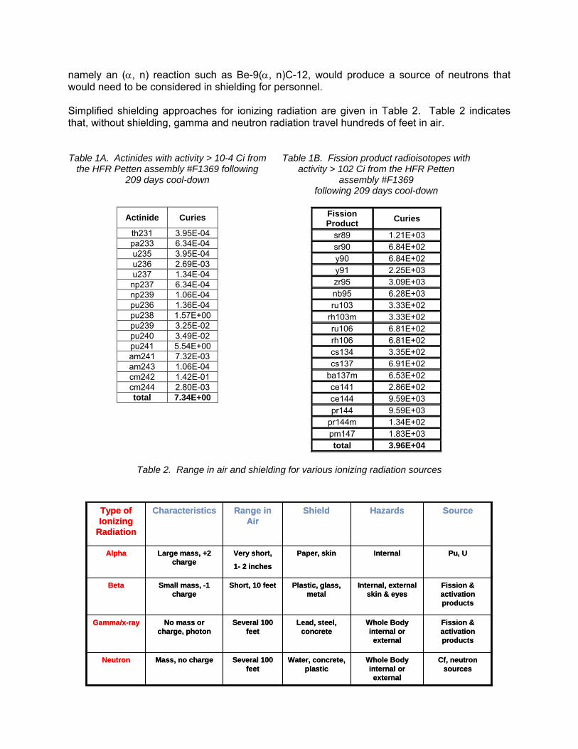
namely an (α, n) reaction such as Be-9(α, n)C-12, would produce a source of neutrons that would need to be considered in shielding for personnel. Simplified shielding approaches for ionizing radiation are given in Table 2. Table 2 indicates that, without shielding, gamma and neutron radiation travel hundreds of feet in air. Table 1A. Actinides with activity > 10-4 Ci from
the HFR Petten assembly #F1369 following 209 days cool-down
Actinide Curies
th231 3.95E-04 pa233 6.34E-04 u235 3.95E-04 u236 2.69E-03 u237 1.34E-04
np237 6.34E-04 np239 1.06E-04 pu236 1.36E-04 pu238 1.57E+00 pu239 3.25E-02 pu240 3.49E-02 pu241 5.54E+00 am241 7.32E-03 am243 1.06E-04 cm242 1.42E-01 cm244 2.80E-03 total 7.34E+00
Table 1B. Fission product radioisotopes with
activity > 102 Ci from the HFR Petten assembly #F1369
following 209 days cool-down
Fission Product Curies
sr89 1.21E+03 sr90 6.84E+02 y90 6.84E+02 y91 2.25E+03 zr95 3.09E+03 nb95 6.28E+03 ru103 3.33E+02
rh103m 3.33E+02 ru106 6.81E+02 rh106 6.81E+02 cs134 3.35E+02 cs137 6.91E+02
ba137m 6.53E+02 ce141 2.86E+02 ce144 9.59E+03 pr144 9.59E+03
pr144m 1.34E+02 pm147 1.83E+03 total 3.96E+04
Table 2. Range in air and shielding for various ionizing radiation sources
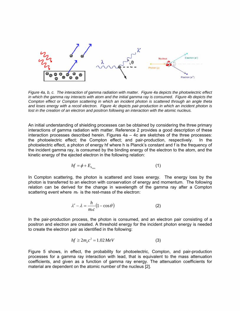
Figure 4a, b, c. The interaction of gamma radiation with matter. Figure 4a depicts the photoelectric effect in which the gamma ray interacts with atom and the initial gamma ray is consumed. Figure 4b depicts the Compton effect or Compton scattering in which an incident photon is scattered through an angle theta and loses energy with a recoil electron. Figure 4c depicts pair-production in which an incident photon is lost in the creation of an electron and positron following an interaction with the atomic nucleus. An initial understanding of shielding processes can be obtained by considering the three primary interactions of gamma radiation with matter. Reference 2 provides a good description of these interaction processes described herein. Figures 4a – 4c are sketches of the three processes: the photoelectric effect; the Compton effect; and pair-production, respectively. In the photoelectric effect, a photon of energy hf where h is Planck’s constant and f is the frequency of the incident gamma ray, is consumed by the binding energy of the electron to the atom, and the kinetic energy of the ejected electron in the following relation:
maxkEhf += φ (1) In Compton scattering, the photon is scattered and loses energy. The energy loss by the photon is transferred to an electron with conservation of energy and momentum. The following relation can be derived for the change in wavelength of the gamma ray after a Compton scattering event where em is the rest-mass of the electron:
( )θλλ cos1−=−′cm
he
(2)
In the pair-production process, the photon is consumed, and an electron pair consisting of a positron and electron are created. A threshold energy for the incident photon energy is needed to create the electron pair as identified in the following:
MeVcmhf e 02.12 2 =≥ (3)
Figure 5 shows, in effect, the probability for photoelectric, Compton, and pair-production processes for a gamma ray interaction with lead, that is equivalent to the mass attenuation coefficients, and given as a function of gamma ray energy. The attenuation coefficients for material are dependent on the atomic number of the nucleus [2].

Figure 5.total maseffect, an An engindescriptiobeam of
coefficienfor the
Exposure The pres“buildup Exposure The concrays will Figure 6Abuildup iBremsstrscattering
. The massss attenuationd pair-produ
neering appon given in Cf monoenerg
nt of exposure
e Rate with N
sence of a sflux,” bφ , in
e Rate with S
cept of buildactually becA and 6B. in lower enrahlung (radg, and pair-p
s attenuationon coefficienuction are sh
proach to eChapter 10 getic gamm
and intrate, in u
No Shield:
shield will rereplacemen
Shield: X =&
up flux is bacome a distrThis reduct
ergy gammiation from dproduction p
n coefficientnt and the chown. [from
evaluate gamof reference
ma rays with
ensity or incunits of m
educe the ext of the incid
E μ0 (0659.0=
ased on the ribution of gtion in intena rays is ddeceleration
processes).
ts of lead ascontributionsreference 2]
mma radiate 2. Consideh initial ene
cident flux ofmilliRoentgen
xposure ratedent flux is u
ba φρμ air)/
phenomenoamma rays
nsity of the gue to gamm
n of electrons
s a function s from the p2]
tion shieldineration is firsergy in a
f gammans per ho
(4
e, and the inused to obtai
(5
on that a monemergent fr
gamma raysma rays fros from the p
of gamma rphotoelectric
ng is summst given to aair with a m
a rays/cm2seur (mR/hr)
4)
ntroduction on:
5)
noenergetic rom the shies at the initim Compton
photoelectric
ray energy. effect, Com
marized froma monodirectmass absor
ec. The equ, is given
of the conce
beam of gaeld as picturial energy wn scattering,c effect, Com
The mpton
m the tional rption
uation by:
ept of
amma red in with a , and
mpton

As an extravelling
where thon the rigat distandeterminbuild up parameteForm is w
where A The consexcept fo
xample, the bg through a s
0 b φφ ×=
e term (μpBght hand sidnce R from istic transpofactors can
ers in the fuwritten as [2]
r(μpB
and α1 and
siderations inor the dose f
buildup flux, shield mater
SBuildup =
R)μ is the bde constitute
the point ort theory or n be expresnction. As a]:
r- 1Aer) μα +=
α2 are the p
n neutron shfrom second
for a point sial is given b
2
R
4R)(e
RBS p
πμμ−
buildup facto the uncollidsource. ThMonte Carlo
ssed in a man example,
r- 2A)e - (1 μα+
parameters th
hielding are sary photons
Figure 6monoenerreference
Figure 6B. from a shie
source of intby:
)
or for the poded flux or flhe buildup o calculation
mathematical, the buildup
hat are func
similar to thas from inelas
6A. Energetic gamm2]
Energy speceld [from refer
tensity S at a
(6
int source, aux of gammfactor can
ns. For simpl function w
p factor for th
(7
tions of the
at for gammstic neutron s
ergy spectruma rays on
ctrum of gamrence 2]
a distance R
6)
and the balaa rays at thebe determiple engineer
with tabulatehe point sou
7)
initial energy
a shielding dscattering, a
um of inc a shield
mma rays eme
R from the so
ance of the te incident enned by invoring analysisd values fo
urce in the T
y.
described aband from rad
cident [from
ergent
ource
terms nergy olved s, the
or the Taylor
bove, iative

capture. Due to the potential for radiative capture from isotopes of the shield material, isotopic rather than elemental composition of the shield medium must be considered. Shine or indirect streaming for shielding neutrons must also be considered. The expressions for radiation exposure from a point source can be used in point kernel methods for a distributed source by deconvolution of the distributed source, and then summation of the exposure results from each element to obtain total exposure due to the distributed source. Several computer codes are available to perform this method of analysis including MicroShield, QAD, QAD-CG, QADMOD, and G3. More accurate and robust, but more complicated engineering analyses can be performed for shielding including deterministic transport theory, and Monte Carlo methods. A good review on the history of shielding and an overview of shielding analysis methods is provided in reference 4. The radioactivity or the strength of the radioactive source is measured in units of becquerels (Bq) where 1 Bq = 1 decay per second. A common unit for measuring radioactivity is the curie (Ci) where 1 Ci = 3.7 x 10¹⁰ decays per second. Radioactivity can lead to exposure and absorbed dose that are described below.
Table 3. Radiation units in conventional and SI units
Several terms are defined to characterize the exposure from radioactive sources as listed in Table 3. The characteristic of a radiation beam that is typically measured is exposure. This quantity expresses how much ionization the beam causes in the air through which it travels. The exposure relates to the electric charge produced in air. The SI unit of radiation exposure is the coulomb per kilogram. It is defined as the quantity of X- or gamma-rays such that the associated electrons emitted per kilogram of air at standard temperature and pressure (STP) produce ions carrying 1 coulomb of electric charge. The Roentgen is defined as the quantity of X- or gamma-rays such that the associated electrons emitted per kilogram of air at STP produce ions carrying 2.58 x 10⁻⁴ coulombs of electric charge. Note that this unit is confined to radiation beams consisting of X-rays or gamma-rays.
ConversionRelates toType of Radiation
Effect OnMeasuresRadiation Unit
1 Sv = 100 rem
10 μGy = 1 mrad
Accounts for Difference in
Dose and Damage
All TypesManDose Equivalence
(Dose Equivalence
= Dose x Quality Factor)
rem (Roentgen Equivalent
Man);
Sievert (Sv)
1 Gy = 100 rad =1 J/kg
10 μGy = 1 mrad
1 Wh/l ≅ 360,000 rad
Energy Deposited
into the Material
All TypesAny MaterialDoserad (Radiation Absorbed
Dose);
Gray (Gy)
1 R = 1000 milliroentgen (mR)
1 C/kg = 3,876 R
Gamma and x-ray
AirExposureRoentgen (R)
C/kg

Energy is deposited in the absorber when radiation interacts with it. The quantity that is measured is called the absorbed dose. The SI unit of absorbed dose is called the gray. The gray, Gy, is defined as the absorption of 1 joule of radiation energy per kilogram of material. The traditional unit of absorbed dose is called the rad (radiation absorbed dose). It is defined as the absorption of 10-2 joules of radiation energy per kilogram of material. The biological effects of absorbed dose are expressed by the effective dose that is equal to a quality factor or weighting factor times the absorbed dose. The effective dose is measured in derived SI units called sieverts (Sv). Additional details on the units for radiation can be found in references 5 and 6. The limits for a radiation worker as dictated in U.S. Code of Federal Regulations [7] is assigned as limits to radiation workers, including those at Department of Energy sites, and members of the public2. Other agencies and commissions, such as the International Commission on Radiation Protection, and the U.S. Environmental Protection Agency develop specify limits for radiation exposure. Chapter 9 of reference 2 provides a discussion of the history of the international and U.S. bodies that have developed standards for radiation protection.
Table 4. Dose limits for radiation workers at a DOE facility
DOE Limit
(rem/yr)
DOE Admin Control
(rem/yr)
SRS Admin Control, Rad Workers
(rem/yr)
Whole Body
5 2 1.0
Extremity
50 n/a n/a
Skin/Other Organs
50 n/a n/a
Lens of Eye
15 n/a n/a
Visitors/Public
0.100 n/a n/a
Pregnant Worker
0.5 during gestation
Administrative limits can be instituted at a site or facility to provide a margin below the legal limits as prescribed in reference 7. Table 4 lists limits for radiation workers at a U.S. DOE facility. Another important construct to control radiation exposure for a worker is the limit for airborne radioisotopes. The permissible limit for inhalation of a radionuclide is the corresponding Annual Limit on Intake expressed as a radioactivity unit that would limit the committed effective dose to 5 rem. Because it is easier to measure and control the concentration of radioactivity in air than to measure or control the intake, the Derived Air Concentration for a radionuclide is defined as radioactivity of a radioisotope per volume such that if the personnel worked the entire year and breathed the air activity, the ALI would not be exceeded. The equation for DAC for a specific radioisotope is:
2 The dose limit to a member of the public is 100 mrem/year

Ci/ml )910 x ALI/(2.4
rate) breathing minuteper ml410 x 2min/hr x 60year x per workedhours Ci)/(2000(in ALIDAC
μ
μ
=
= (8)
For multiple radioisotopes, the sum of the air concentration, Ci for each radioisotope, divided by its DACi must be less than 1. Additional legal limits including those for lifetime exposures for radiation workers are contained in reference 7. It is emphasized that time, distance, and shielding are all practical methods for using engineering and administrative controls to reduce personnel exposure and ensure radiation workers are well within the legal limits.
Radiolysis Radiolysis, the molecular breakdown of a material as a result of radiation absorbed dose, can strongly affect chemical processes. The radiolytic production rate of species is characterized by the G-value that is the number of molecules of the species produced per 100 eV of absorbed energy. The G-value is typically dependent on the radiation type - that is, particles that deposits their energy in a small linear of material is referred as high Linear Energy Transfer (LET) radiation whereas particles, or gamma rays, that deposit their energy in along a greater length in a material are low LET radiation. Figures 7A and 7B depict low and high LET production of radiolytic products, respectively.
Figure 7A. Low Linear Energy Transfer results in radiolysis product (e.g. molecular products and free radicals) regions being created at widely spaced regions. Figure 7B – High Linear Energy Transfer radiation results in a high concentration of radiolysis products. Another concept in radiolysis is that concept of forward (radiolytic process driven) and back reactions. The net effect is best evaluated by benchmarked experiments in irradiators, especially when addressing the effects of impurity species in the reactions. Even a simple system such as pure water has several potential forward and back reactions that are listed as follows: Forward Reactions: 2222
2 , , , , , HOHHeOHOHOH aqaq
radiationincident −+⎯⎯⎯⎯⎯ →⎯ (9)

Back Rea
A strongreactionsa chemic Three keas somethoroughoperation Tri-n-butyprocessereactions TBP + H2Dibutyl PMonobuty
actions:
forward reas. Impuritiescal system [8
ey separatioe examples hly reviewedns to ensure
yl Phosphates as discuss can decom
2O → Dibutyl Phosphoric Ayl Phosphoric
OHH 22+HOH 2+
OHH 22 +
action proces in the wate8].
ns processefor separat, and any ne
e process co
te (TBP) is sed in other
mpose TBP in
Phosphoric AAcid (HDBP)
Acid (H2MBP
HOH +→OHH 2+→
OHO 22 2→
esses make er may act a
es and effections procesew process nditions are
an ester ur chapters ofn the followi
Acid (HDBP) ++ H2O →
P) + H2O → P
OH2 O
reaction pras catalysts
cts of radiolysses. A proshould be cas expected
used in solvf this book. ng breakdow
+ Butyl AlcohMonobutyl PPhosphoric A
roducts that to drive the
ysis on thesoposed sepchecked for d and manag
vent extractiBoth chemi
wn sequence
ol Phosphoric AAcid (H3PO4)
Figure 8 –for yieldsHDBP frodiluent so
themselvesforward or b
se processesparations pro
radiolysis isgeable.
ion in the Pcal (hydrolyte [9]:
Acid (H2MBP+ Butyl Alcoh
– Correlations (G-values) om irradiationolutions [from
(10)
s interact in back reactio
s are highligocess shoulssues prior t
PUREX andtic) and radi
) + Butyl Alhol
n of publishedof total acid
n of TBP alipreference 9].
back ons in
ghted ld be to full
d HM olytic
lcohol
d data d and phatic

Reference 9 is a key reference providing a comprehensive set of basic data concerning the products of radiolysis of pure TBP, of various hydrocarbon diluents, and of solutions of TBP in these diluents. In some experiments these materials were anhydrous whereas in others they were saturated with water. The degradation products from the radiolysis of TBP, wet or dry, include HDBP, H2MBP, H3PO4, H2, CH4, C2H4, C2H6, C4H9OH, and other hydrocarbons. Of these, the greatest product yield is HDBP. The results also show a greater yield of HDBP in anhydrous condition (G = 3 acid molecules/100 eV) compared to the water-saturated condition (G = 1.8 acid molecules/100 eV) (see Figure 9).
Figure 9. TBP degradation rates due to acid hydrolysis, alpha radiolysis, and metal-ion-induced hydrolysis at 80°C (shown a mg of plutonium complexed by degradation products for each factor) [from reference 10]. Figure 10 from reference 10 show the partition in breakdown rate of TBP at 80°C due to acid hydrolysis, alpha radiolysis, and metal-ion-induced hydrolysis. Reference 10 shows a strong effect of temperature on the breakdown rate for both hydrolysis and radiolysis of TBP. Ferrous sulfamate is an important reductant in which Fe(II) is used to reduce Np(V) to Np(IV) and Pu(IV) to Pu(III) for subsequent solvent extraction or ion exchange of the Np and Pu from irradiated uranium fuels. The sulfamate specie, (NH2SO3
-)2, acts to prevent NO3-caused oxidation of Fe(II). Reference 11 describes the experimentation and results in which actual fuel solutions were used in a test and gamma irradiation was used as a radiation source to investigate to radiolytic-induced oxidation of Fe(II) and destruction of sulfamic acid (SA). Figures 10A and 10B shows the results from tests with actual process solutions that if Fe(II) is not present, there is almost immediate reversion of Np(IV) to Np(V) and Pu(III) to Pu(IV). These results in reference 10 show that a high dose rate process solution can cause rapid depletion of

Fe(II). AFe(II) (se Figure 10AU-235 [fro(IV) and indramatic c
Additional reee Figure 11
0A. Shows thom reference ndirectly the ochange when
esults valida).
he depletion o11]. Figure
oxidation of Nn the Fe (II) io
ate gamma
of the ferrous 10B shows th
Np (IV) to Np on is reduced
irradiation t
(Fe(II)) ion frhe dramatic c(V) as its Figbelow a certa
testing to in
rom radiolysischange to caugures 10A anain level by ra
nvestigate th
s by dissolveduse oxidation nd 10B taken adiolysis.
he breakdow
d fission prodof of Pu (III) together sho
wn of
duct of to Pu
ow the

Ion excheffects oevolve gorganic idamage,significanresins.
Figure 12resins [fro
hange mediaon ion exchaas when exon exchang but the ovent loss of ion
2. Reduction om reference
a are used ange materxposed to raers. Polyco
erall propertin exchange
in the ion ex12]
Figur(Fe(Ito inrefer
extensively rials [12] shadiation. D
ondensation-es of this typcapacity in
xchange capa
re 11. This II)) ion from rnvestigate radrence 11].
in separatiows resins
Doses of 10-type ion expe of ion exseveral 4%
acity of severa
figure showradiolysis by diolysis effec
ons processlose ion ex
5 to 106 Gychanger mechange med
% cross-linke
al 4% cross-li
ws the depletCo-60 gamm
cts in proces
ses. A revxchange capy are significedia are residia is poor. ed styrene-D
inked styrene
tion of the fema irradiation ss solutions
view of radiopability and cant to syntstant to radiFigure 12 s
DVB sulfonic
e-DVB sulfonic
errous used [from
olysis may
thetic iation hows
c acid
c acid

Radiation Effects on Materials Both polymers and austenitic stainless steel are important materials for gaskets and valve seats; and process equipment (tanks, valves, piping), respectively in separations processing equipment. Polymer selection is often principally dictated by chemical resistance rather than strictly radiation resistance, and therefore the use of polymers should be limited to the extent practical and/or designed for replacement.
Effects on Polymers Polymers are complex molecules that are formed by chains of duplicated groups of atoms that themselves are typically linked by covalent bonds along a “backbone” of carbon or silicon atoms. The irradiation effects in polymers important to seals in separations processing equipment include loss of sealing ability, gas evolution, and increased leachability of constituents or loss of chemical resistance of the polymer. Factors important to cause radiation effects in polymers are the total dose (in rads), the dose rate, and the presence of O2; most polymers are susceptible to degradation via oxidation of the resinous molecules. The primary types of degragation mechanisms are: 1) Scission – molecular bonds are ruptured with an effective reduction in molecular weight and strength, and gas evolution; and 2) Cross-linking - polymer molecules are linked to form large 3D molecular networks which causes hardening and embrittlement; and 3) enhanced oxidation of the resinous molecules that cause severe loss of strength. Typically, one degradation mechanism is dominant; however it is not always easy to predict the effect. For carbon-carbon chains (backbones), cross-linking will occur is H is attached to the carbon. In contrast, scission will occur at tetra-substituted carbon [13]. Polymers with aromatic molecules are more resistant to radiation damage than aliphatics. Polystyrenes and polyamides are aromatics with good radiation stability. Tables 5 and 6 from reference 13 describe the radiation resistance of a listing of polymeric materials.

Figure 13reference An imporrate in wenvironmterm expcable insoxidation For sepafluoropolchemical
• T• Ju• V
so• K• H• T• K
so
3. Dose to temperature
rtant note ohich a high d
ment for matposures for asulation polyn degradatio
arations seymers that hl-resistance
Teflon –initialumper Gask
Viton® B – Folutions
Kalrez® FFKHalar®/ECTFTefzel®/ETFEKynar®/PVDFolutions (stre
50% elongatof 50°C) [from
f caution in dose rate exterial irradiaa 40-year seymer. It is n mechanism
rvice, stronhave been rservice:
l damage at kets: Teflon-KM fluoroela
M perfluoroeFE – low perE copolymerF – most resess-cracking
tion loss in Pm reference 1
the use of xposure mayted to a comrvice life masuspected
m that cause
ng acid chereviewed and
1-5E4 rad, sasbestos (fuastomer, old
elastomer –rmeability, por – used in Hsistant fluorog).
PVC cable in14]
polymers iny not be indimmon doseay fail soonethat low do
es the dose
emical resisd/or used fo
severe damunctional to 1der formulatio
expensive, ossible chlor
HLW transfeopolymer, les
sulation (data
n radiation scative of ag. That is, m
er. Figure 13ose rate irrarate effect.
stance is neor service at
age at 1-10 100-1000 Mons with lea
resistant to aride releaser lines, ball vss resistant
a shifted by
ervice is theing experien
materials “qu3 shows thisadiation may
eeded. Ththe Savann
Mrad rad)
ad oxide, not
acids at high
valves to strong nit
superposition
e effects of nce in a low ualified” in ss effect on a y exacerbate
he followingnah River Sit
t suitable for
h temp
tric acid or N
n to a
dose dose
short-PVC
e the
g are te for
r TBP
NaOH
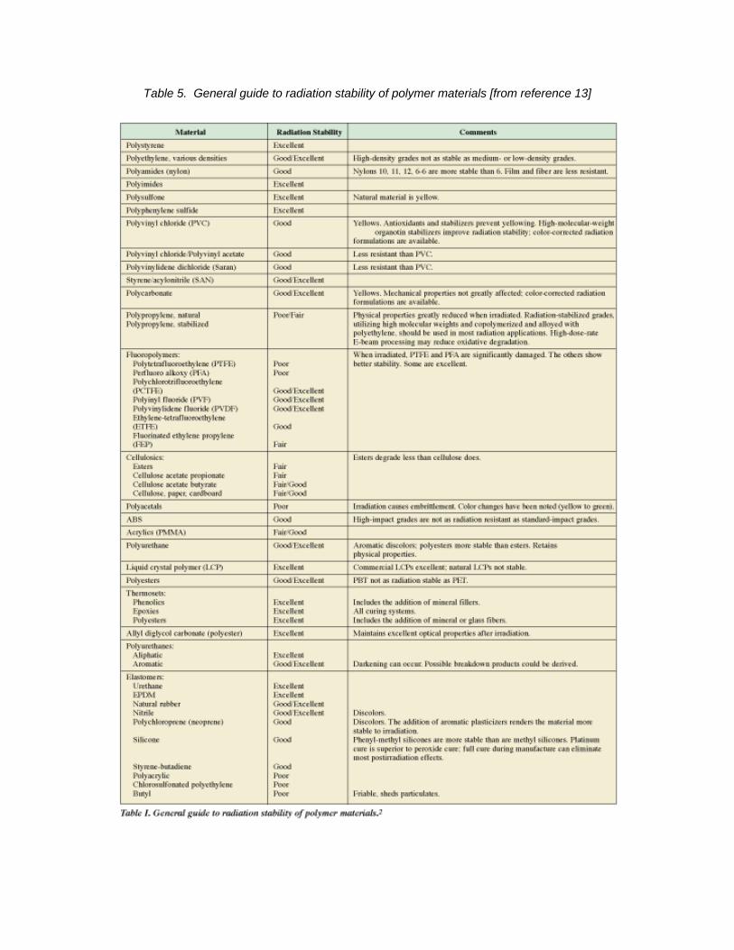
Table 5. General guide to radiation stability of polymer materials [from reference 13]

Table 6. Dose limits for radiation applications for various polymer materials [from reference 13]

Effects Austenitiprocess vformationblack spoconsists are forme(PKAs). schematmetals a
Figure 14Knock-on displacem
on Metals c stainless vessels. Thn of small “bot damage, tof small dised directly fo The PKAs ically in Figund alloys is g
4. Basic conc Atoms in
ments
steels are these materialack spot” dathat is smalllocation loopollowing theare themse
ure 14. A regiven in refe
cept of the dathe materia
typically useals are subjeamage at lowl extend defeps, stacking
e creation of elves createeview of the erence 15.
amage procesal which the
ed as the mect to radiatiw irradiationects in the c fault tetrahedisplaceme
ed by the infundamenta
ss in which themselves cre
materials of on hardenin
n temperaturcrystalline stredral, or vac
ent cascadesncident partial aspect of
he incident raeate damage
constructiong and embrres (Tirradiation ructure of thcancy/intersts by primarycle (e.g. neradiation eff
adiation partice cascades
n for pipingrittlement thr< 0.3 Tm.p.).
he stainless stitial clusters
y knock-on aeutron) as shfects in irrad
cle creates Prwith much
g and rough The steel, s that atoms hown
diated
rimary local
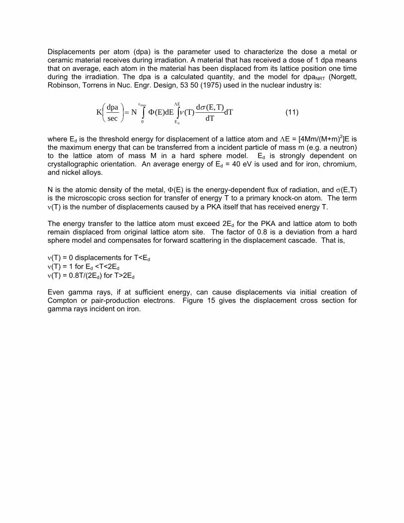
Displacements per atom (dpa) is the parameter used to characterize the dose a metal or ceramic material receives during irradiation. A material that has received a dose of 1 dpa means that on average, each atom in the material has been displaced from its lattice position one time during the irradiation. The dpa is a calculated quantity, and the model for dpaNRT (Norgett, Robinson, Torrens in Nuc. Engr. Design, 53 50 (1975) used in the nuclear industry is:
dTdT
T)(E,d(T)(E)dENsecdpaK
maxE
d0
E
E∫ ∫
Λ
Φ=⎟⎠⎞
⎜⎝⎛ σν (11)
where Ed is the threshold energy for displacement of a lattice atom and ΛE = [4Mm/(M+m)2]E is the maximum energy that can be transferred from a incident particle of mass m (e.g. a neutron) to the lattice atom of mass M in a hard sphere model. Ed is strongly dependent on crystallographic orientation. An average energy of Ed = 40 eV is used and for iron, chromium, and nickel alloys. N is the atomic density of the metal, Φ(E) is the energy-dependent flux of radiation, and σ(E,T) is the microscopic cross section for transfer of energy T to a primary knock-on atom. The term ν(T) is the number of displacements caused by a PKA itself that has received energy T. The energy transfer to the lattice atom must exceed 2Ed for the PKA and lattice atom to both remain displaced from original lattice atom site. The factor of 0.8 is a deviation from a hard sphere model and compensates for forward scattering in the displacement cascade. That is, ν(T) = 0 displacements for T<Ed ν(T) = 1 for Ed <T<2Ed ν(T) = 0.8T/(2Ed) for T>2Ed Even gamma rays, if at sufficient energy, can cause displacements via initial creation of Compton or pair-production electrons. Figure 15 gives the displacement cross section for gamma rays incident on iron.
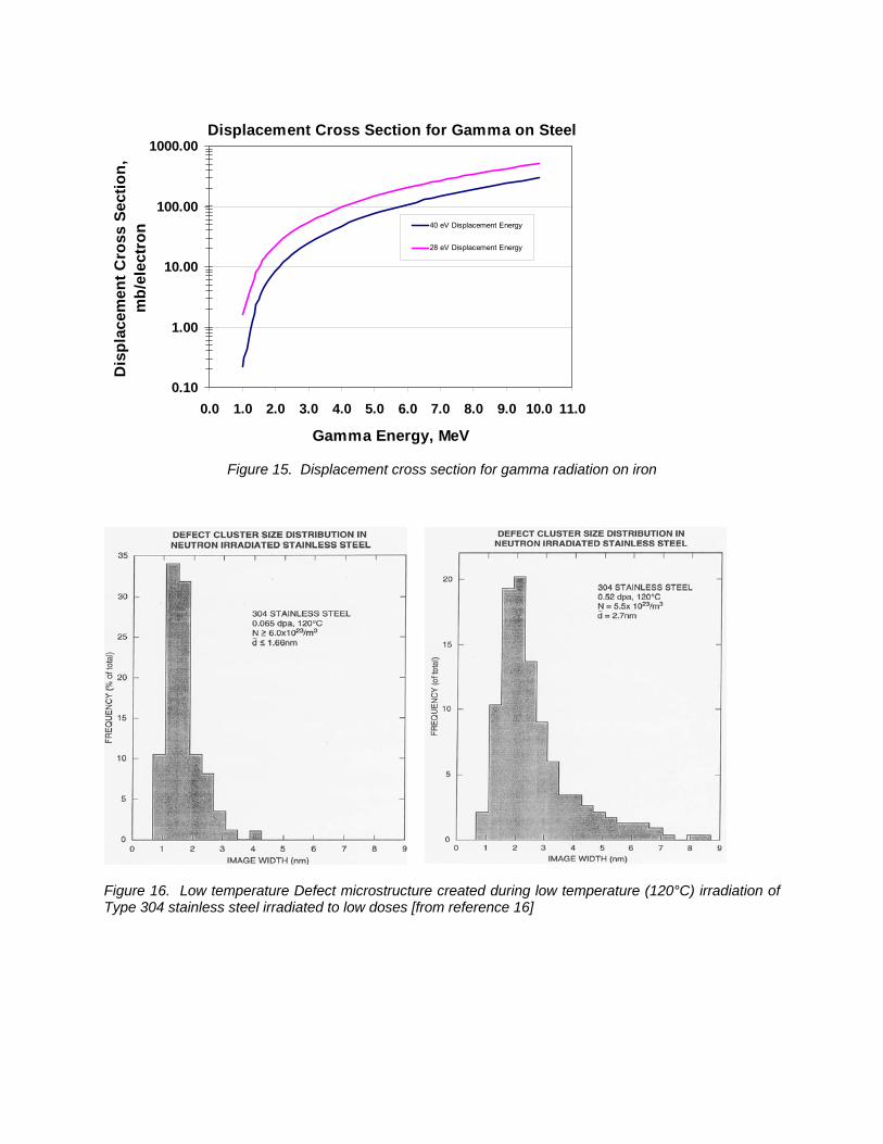
Figure 15. Displacement cross section for gamma radiation on iron
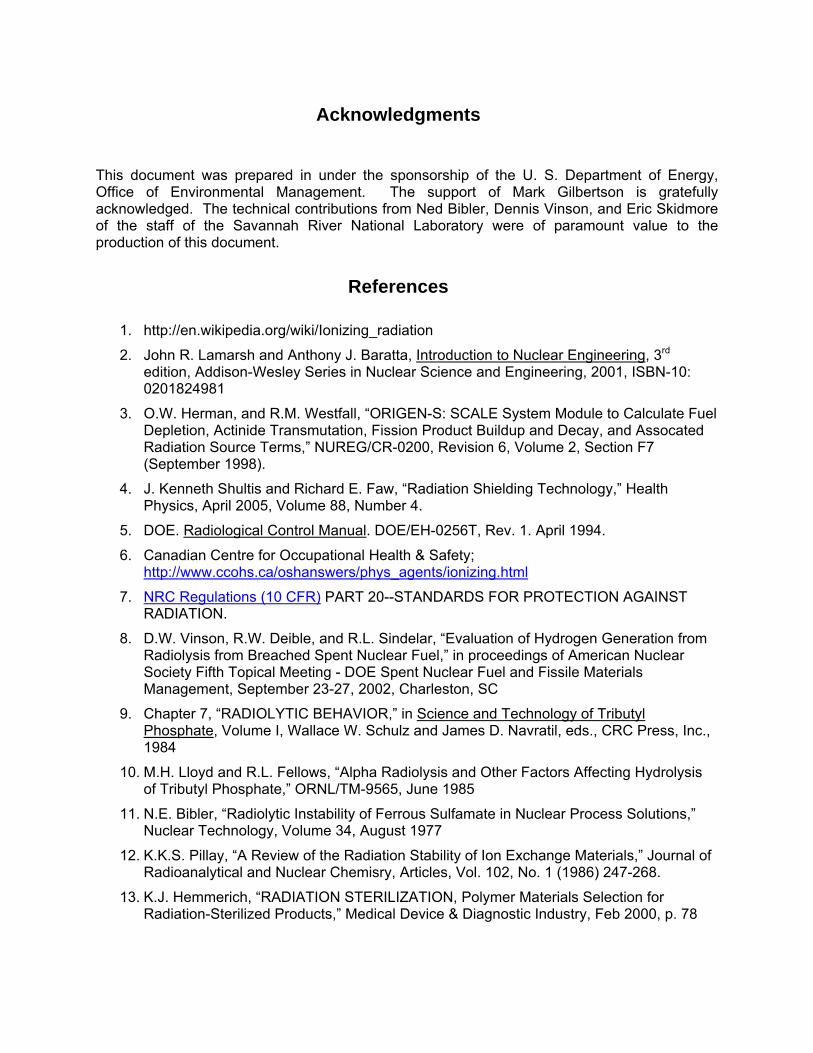
Figure 16. Low temperature Defect microstructure created during low temperature (120°C) irradiation of Type 304 stainless steel irradiated to low doses [from reference 16]
Displacement Cross Section for Gamma on Steel
0.10
1.00
10.00
100.00
1000.00
0.0 1.0 2.0 3.0 4.0 5.0 6.0 7.0 8.0 9.0 10.0 11.0
Gamma Energy, MeV
Dis
plac
emen
t Cro
ss S
ectio
n,
mb/
elec
tron
40 eV Displacement Energy
28 eV Displacement Energy

Only extremely low levels of displacement damage would be expected over the lifetime of process equipment. A fair representation of the damage microstructure that could be formed in process equipment is given in Figure 16. The mechanical response from this damaged microstructure would be slight radiation hardening. That is, radiation damage to process equipment is not considered significant to stainless steels subjected to attendant radiation in the separations processing.
Acknowledgments This document was prepared in under the sponsorship of the U. S. Department of Energy, Office of Environmental Management. The support of Mark Gilbertson is gratefully acknowledged. The technical contributions from Ned Bibler, Dennis Vinson, and Eric Skidmore of the staff of the Savannah River National Laboratory were of paramount value to the production of this document.
References
1. http://en.wikipedia.org/wiki/Ionizing_radiation
2. John R. Lamarsh and Anthony J. Baratta, Introduction to Nuclear Engineering, 3rd edition, Addison-Wesley Series in Nuclear Science and Engineering, 2001, ISBN-10: 0201824981
3. O.W. Herman, and R.M. Westfall, “ORIGEN-S: SCALE System Module to Calculate Fuel Depletion, Actinide Transmutation, Fission Product Buildup and Decay, and Assocated Radiation Source Terms,” NUREG/CR-0200, Revision 6, Volume 2, Section F7 (September 1998).
4. J. Kenneth Shultis and Richard E. Faw, “Radiation Shielding Technology,” Health Physics, April 2005, Volume 88, Number 4.
5. DOE. Radiological Control Manual. DOE/EH-0256T, Rev. 1. April 1994.
6. Canadian Centre for Occupational Health & Safety; http://www.ccohs.ca/oshanswers/phys_agents/ionizing.html
7. NRC Regulations (10 CFR) PART 20--STANDARDS FOR PROTECTION AGAINST RADIATION.
8. D.W. Vinson, R.W. Deible, and R.L. Sindelar, “Evaluation of Hydrogen Generation from Radiolysis from Breached Spent Nuclear Fuel,” in proceedings of American Nuclear Society Fifth Topical Meeting - DOE Spent Nuclear Fuel and Fissile Materials Management, September 23-27, 2002, Charleston, SC
9. Chapter 7, “RADIOLYTIC BEHAVIOR,” in Science and Technology of Tributyl Phosphate, Volume I, Wallace W. Schulz and James D. Navratil, eds., CRC Press, Inc., 1984
10. M.H. Lloyd and R.L. Fellows, “Alpha Radiolysis and Other Factors Affecting Hydrolysis of Tributyl Phosphate,” ORNL/TM-9565, June 1985
11. N.E. Bibler, “Radiolytic Instability of Ferrous Sulfamate in Nuclear Process Solutions,” Nuclear Technology, Volume 34, August 1977
12. K.K.S. Pillay, “A Review of the Radiation Stability of Ion Exchange Materials,” Journal of Radioanalytical and Nuclear Chemisry, Articles, Vol. 102, No. 1 (1986) 247-268.
13. K.J. Hemmerich, “RADIATION STERILIZATION, Polymer Materials Selection for Radiation-Sterilized Products,” Medical Device & Diagnostic Industry, Feb 2000, p. 78
14. NUREG/CR-2877, SAND81-2613, “Investigation of Cable Deterioration in the Containment Building of the Savannah River Nuclear Reactor,” K.T. Gillen, R.L. Clough, L.H. Jones, August 1982.
15. S.J. Zinkle, “Microstructure Evolution in Irradiated Metals and Alloys: Fundamental Aspects," NATO Advanced Study Institute, Course on Radiation Effects in Solids, Erice, Sicily, Italy, July 17-29, 2004.
16. Chapter 9, “Physics of Radiation Damage in Metals,” in Nuclear Materials, Volume 10B, B.R.T. Frost, ed., Materials Science and Technology Series, VCH Verlagsgesellschaft mbH and VCH Publishers,Inc., 1994.
17. M.J. Norgett, M.T. Robinson, and I.M. Torrens,1975, Nucl. Eng. Des., 33, p. 50 18. S.J. Zinkle and R.L. Sindelar, "Defect Microstructures in Neutron-Irradiated Copper and
Stainless Steel," J. Nucl. Mat. 155-157 (1988) p. 1196.