
0.46 cu.in. displacement 2-stroke 0.70 cu.in. displacement ...
14
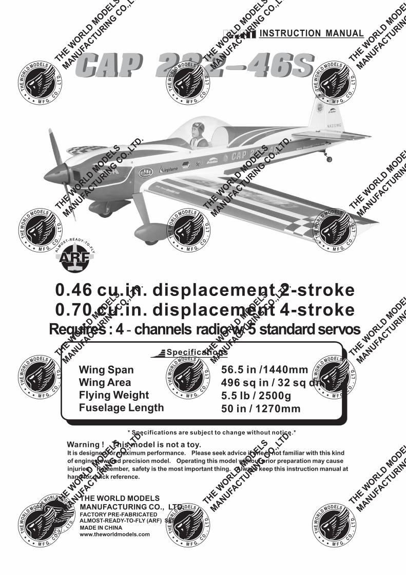
Wing Span Wing Area Flying Weight Fuselage Length 56.5 in /1440mm 496 sq in / 32 sq dm 5.5 lb / 2500g 50 in / 1270mm * Specifications are subject to change without notice.* INSTRUCTION MANUAL Specifications THE WORLD MODELS MANUFACTURING CO., LTD. FACTORY PRE-FABRICATED ALMOST-READY-TO-FLY (ARF) SERIES MADE IN CHINA www.theworldmodels.com Warning ! This model is not a toy. It is designed for maximum performance. Please seek advice if one is not familiar with this kind of engine powered precision model. Operating this model without prior preparation may cause injuries. Remember, safety is the most important thing. Always keep this instruction manual at hand for quick reference. A L M O S T - R E A D Y - T O - F L Y Requires : 4 channels radio w 5 standard servos - / 0.46 cu.in. displacement 2-stroke 0.70 cu.in. displacement 4-stroke
Transcript of 0.46 cu.in. displacement 2-stroke 0.70 cu.in. displacement ...
Wing Span
Wing Area
Flying Weight
Fuselage Length
56.5 in /1440mm
496 sq in / 32 sq dm
5.5 lb / 2500g
50 in / 1270mm
* Specifications are subject to change without notice.*
INSTRUCTION MANUAL
Specifications
THE WORLD MODELSMANUFACTURING CO., LTD.FACTORY PRE-FABRICATEDALMOST-READY-TO-FLY (ARF) SERIES
MADE IN CHINA
www.theworldmodels.com
Warning ! This model is not a toy.It is designed for maximum performance. Please seek advice if one is not familiar with this kind
of engine powered precision model. Operating this model without prior preparation may cause
injuries. Remember, safety is the most important thing. Always keep this instruction manual at
hand for quick reference.
AL
M
OS T- R E A D Y- TO
- FLY
Requires: 4 channels radio w 5 standardservos- /
0.46 cu.in. displacement 2-stroke0.70 cu.in. displacement 4-stroke
P.1
INDEX
BEFORE YOU BEGIN
PARTS LIST
ASSEMBLY
SAFETY PRECAUTIONS
P. 1
P. 2
P. 3 - 10
P. 10
BEFORE YOU BEGIN
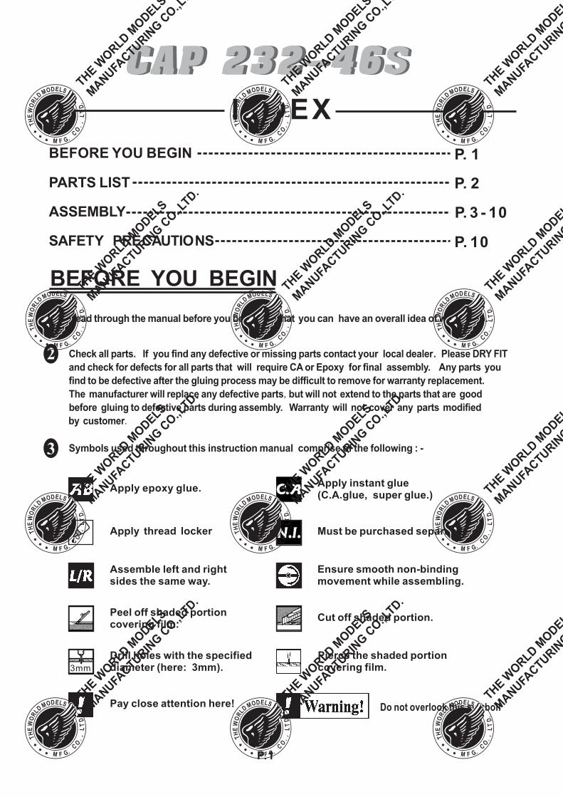
Check all parts. If you find any defective or missing parts contact your local dealer. Please DRY FIT
and check for defects for all parts that will require CA or Epoxy for final assembly. Any parts you
find to be defective after the gluing process may be difficult to remove for warranty replacement.
The manufacturer will replace any defective parts but will not extend to the parts that are good
before gluing to defective parts during assembly. Warranty will not cover any parts modified
by customer
,
.
Read through the manual before you begin so that you can have an overall idea of what to do.,
Symbols used throughout this instruction manual comprise of the following : -
1
2
3
Do not overlook this symbol!
Cut off shaded portion.Peel off shaded portioncovering film.
Pay close attention here!
Pierce the shaded portioncovering film.
Must be purchased separately!
Drill holes with the specifieddiameter (here: 3mm).3mm
Ensure smooth non-bindingmovement while assembling.
Apply instant glue(C.A.glue, super glue.)
Assemble left and rightsides the same way.
Apply epoxy glue.
Apply thread locker
P.2
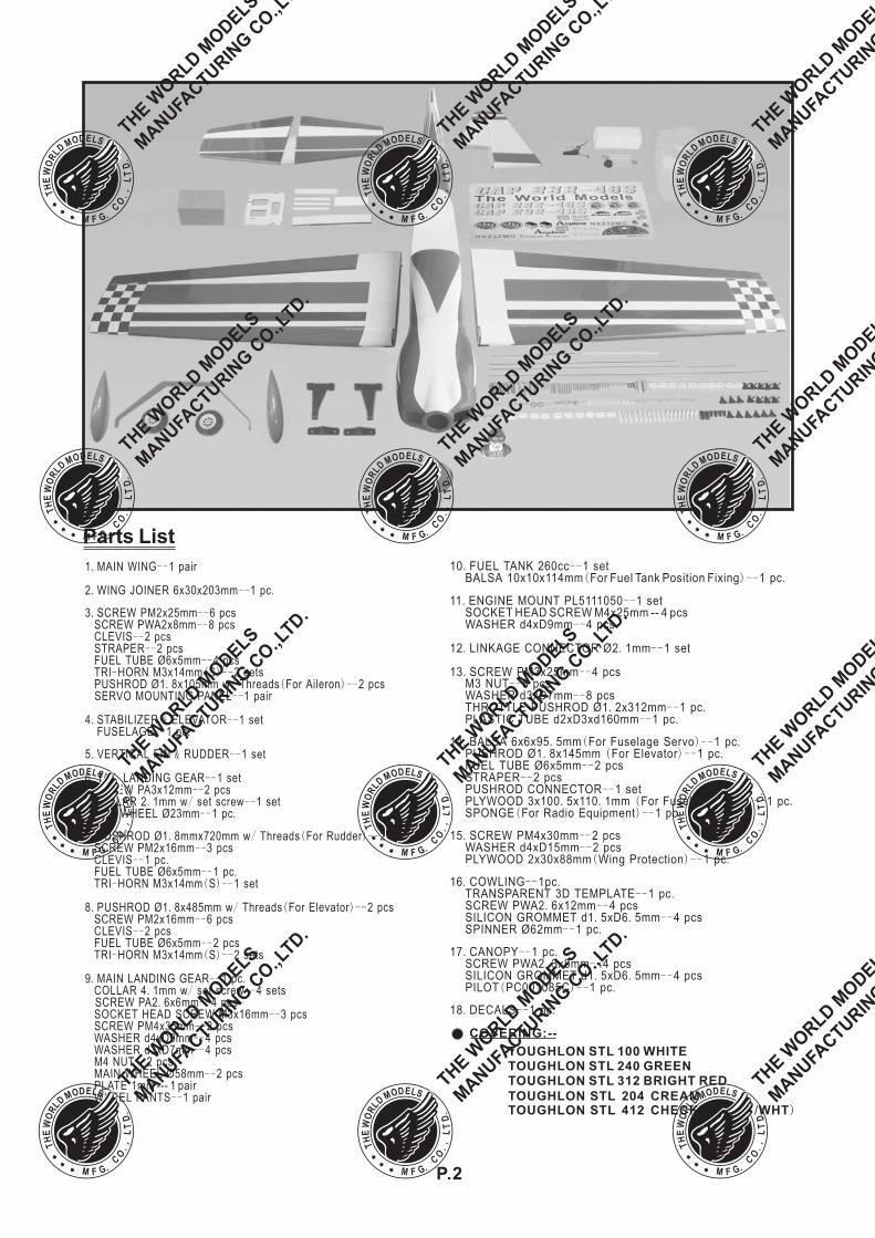
Parts List
COVERING:--
TOUGHLON STL 100 WHITETOUGHLON STL 240 GREENTOUGHLON STL 312 BRIGHT RED
TOUGHLONTOUGHLON ( )
STL 204 CREAMSTL 412 CHECKER RED WHT/
1 MAIN WING 1 pair
2 WING JOINER 6x30x203mm 1 pc
3 SCREW PM2x25mm 6 pcsSCREW PWA2x8mm 8 pcsCLEVIS 2 pcsSTRAPER 2 pcsFUEL TUBE Ø6x5mm 4 pcsTRI HORN M3x14mm S 2 setsPUSHROD Ø1 8x105mm w Threads For Aileron 2 pcsSERVO MOUNTING PANEL 1 pair
4 STABILIZER ELEVATOR 1 setFUSELAGE 1 pc
5 VERTICAL FIN RUDDER 1 set
6 TAIL LANDING GEAR 1 setSCREW PA3x12mm 2 pcsCOLLAR 2 1mm w set screw 1 setTAIL WHEEL Ø23mm 1 pc
7 PUSHROD Ø1 8mmx720mm w Threads For Rudder 2 pcsSCREW PM2x16mm 3 pcsCLEVIS 1 pcFUEL TUBE Ø6x5mm 1 pcTRI HORN M3x14mm S 1 set
8 PUSHROD Ø1 8x485mm w Threads For Elevator 2 pcsSCREW PM2x16mm 6 pcsCLEVIS 2 pcsFUEL TUBE Ø6x5mm 2 pcsTRI HORN M3x14mm S 2 sets
9 MAIN LANDING GEAR 1 pcCOLLAR 4 1mm w set screw 4 setsSCREW PA2 6x6mm 4 pcsSOCKET HEAD SCREW M3x16mm 3 pcsSCREW PM4x35mm 2 pcsWASHER d4xD9mm 4 pcsWASHER d3xD7mm 4 pcsM4 NUT 2 pcsMAIN WHEEL Ø58mm 2 pcsPLATE 1mm --- 1 pairWHEEL PANTS 1 pair
. --
. -- .
. ----
----
--- ( )--
. / ( )----
. & ---- .
. & --
. ----
. / ---- .
. . / ( )----
-- .-- .
- ( )--
. . / ( )----
----
- ( )--
. -- .. / --
. ----
------
----
--
10 FUEL TANK 260cc 1 setBALSA 10x10x114mm For Fuel Tank Position Fixing 1 pc
M3 NUT 8 pcsWASHER d3xD7mm 8 pcsTHROTTLE PUSHROD Ø1 2x312mm 1 pcPLASTIC TUBE d2xD3xd160mm 1 pc
14 BALSA 6x6x95 5mm For Fuselage Servo 1 pcPUSHROD Ø1 8x145mm For Elevator 1 pcFUEL TUBE Ø6x5mm 2 pcsSTRAPER 2 pcsPUSHROD CONNECTOR 1 setPLYWOOD 3x100 5x110 1mm For Fuselage Servo 1 pcSPONGE For Radio Equipment 1 pc
15 SCREW PM4x30mm 2 pcsWASHER d4xD15mm 2 pcsPLYWOOD 2x30x88mm Wing Protection 1 pc
16 COWLING 1pcTRANSPARENT 3D TEMPLATE 1 pcSCREW PWA2 6x12mm 4 pcsSILICON GROMMET d1 5xD6 5mm 4 pcsSPINNER Ø62mm 1 pc
17 CANOPY 1 pcSCREW PWA2 3x8mm 4 pcsSILICON GROMMET d1 5xD6 5mm 4 pcsPILOT PC001085C 1 pc
18 DECALS 1 pc
. --( )-- .
----
. -- .-- .
. . ( )-- .. ( )-- .
----
--. . ( )-- .
( )-- .
. ----
( )-- .
. -- .-- .
. --. . --
-- .
. -- .. --
. . --( )-- .
. -- .
11 ENGINE MOUNT PL5111050 1 setSOCKET HEAD SCREW M4x25mm -- 4 pcsWASHER d4xD9mm 4 pcs
12 LINKAGE CONNECTOR Ø2 1mm 1 set
13 SCREW PM3x25mm 4 pcs
. --
--
. . --
. --
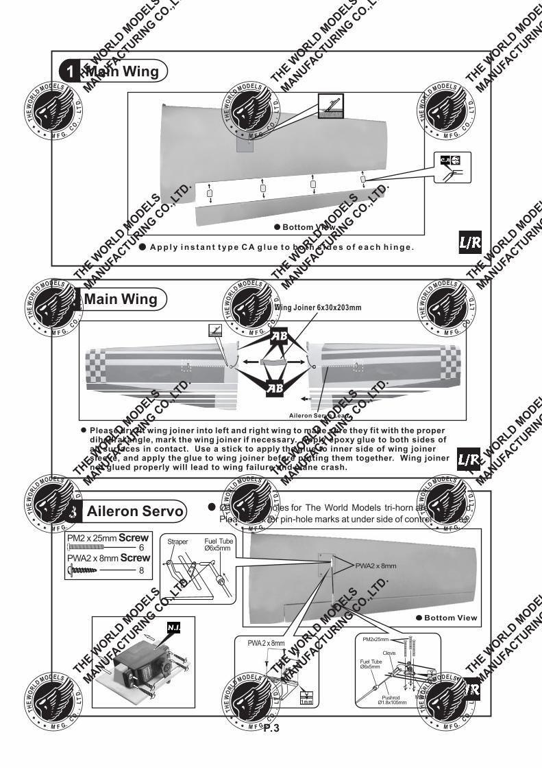
Main Wing2Wing Joiner 6x30x203mm
Aileron Servo Lead
Please dry fit wing joiner into left and right wing to make sure they fit with the properdihedral angle, mark the wing joiner if necessary. Apply epoxy glue to both sides ofall surfaces in contact. Use a stick to apply the glue to inner side of wing joinersleeve, and apply the glue to wing joiner before putting them together. Wing joinernot glued properly will lead to wing failure and plane crash.
1 Main Wing
P.3
A p p l y i n s t a n t t y p e C A g l u e t o b o t h s i d e s o f e a c h h i n g e .
Bottom View
Aileron Servo3
PWA2 x 8mm
Bottom View
Ø1mm pilot holes for The World Models tri-horn are pre-drilled.
Please look for pin-hole marks at under side of control surfaces.
6PM2 x 25mm Screw
8
PWA2 x 8mm Screw
Fuel Tube6x5mmØ
PM2x25mm
-Tri hornM3x14mm
Clevis
2mm
Pushrod1.8x105mmØ
PWA2 x 8mm
1 m m
Fuel Tube6x5mmØ
Straper
1.5mm
2.5mm
Bottom View
P.4
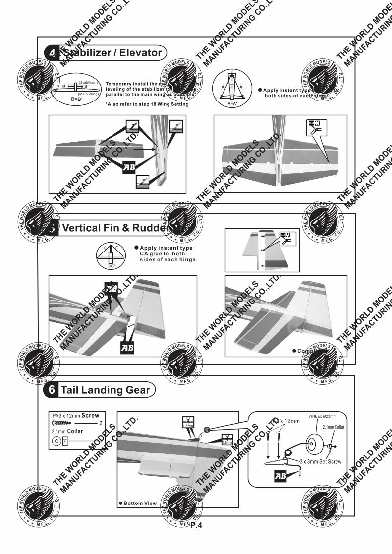
6 Tail Landing Gear
2.1mm Collar
1
PA3 x 12mm Screw2
3 x 3mm Set Screw
PA3 x 12mmWHEEL 23mmØ
2.1mm Collar
Stabilizer / Elevator4
Apply instant type CA glue toboth sides of each hinge.
Temporary install the main wing, adjustleveling of the stabilizer to make it asparallel to the main wing as possible.
(Stabilizer)
(Main Wing)
B B'
B B'
Vertical Fin & Rudder5
Apply instant typeCA glue to bothsides of each hinge.
C=C'
C C
Completed
*Also refer to step 18 Wing Setting
A A'
A=A'
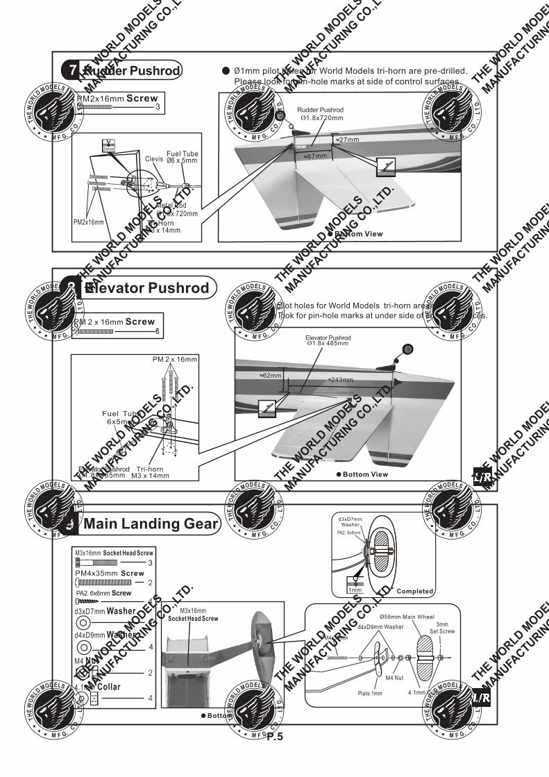
≈243mm≈62mm
Elevator Pushrod1.8x 485mm
Bottom View
8 Elevator Pushrod
Ø 1mm pilot holes for World Models tri-horn are pre-drilled.
Please look for pin-hole marks at side of control surfaces.
PM 2 x 16mm Screw
P.5
Rudder Pushrod7
≈27mm
≈87mm
Rudder Pushrod
1.8x720mm
Bottom View
PM2x16mm
ClevisFuel Tube
6 x 5mmØ
Tri-Horn
2mm
Metal Rod1.8x 720mm
M3 x 14mm
Ø 1mm pilot holes for World Models tri-horn are pre-drilled.
Please look for pin-hole marks at under side of control surfaces.
PM2x16mm Screw3
Elevator Pushrod1.8x 485mm
Fuel Tube6x5mmØ
PM 2 x 16mm
Tri-hornM3 x 14mm
Main Landing Gear9
Bottom View
M4 Nut
4.1mm Collar
2
d4xD9mm Washer
4
2
4
PA2 6x6mm. Screw4
PM4x35mm Screw
3
M3x16mm Socket Head Screw
M3x16mmSocket Head Screw
d3xD7mm Washer
4
1mm
PA2 6x6mm.
d3xD7mmWasher
Completed
4.1mm Collar
M4 Nut
d4 9xD mm Washer 3mmSet Screw
Ø58mm Main Wheel
PM4x35mm
Plate 1mm
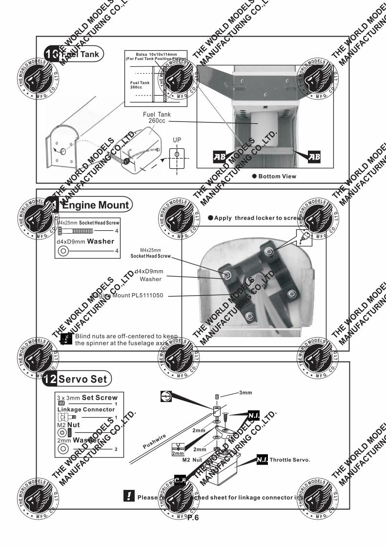
10 Fuel Tank
Bottom View
Fuel Tank260cc
UP
Balsa 10x10x114mm
Fuel Tank260cc
(For Fuel Tank Position Fixing)
Pushwire
3mm
Throttle Servo.
2mm
Servo Set
2mm
3 x 3mm Set Screw
Linkage Connector
M2 Nut
2mm Washer
1
1
1
2
12
M2 Nut
Please refer to attached sheet for linkage connector installation.
2mm
Engine Mount11
d4xD9mm Washer
4
d4xD9mm
Washer
!Blind nuts are off-centered to keepthe spinner at the fuselage axis.
Apply thread locker to screws.
Engine Mount PL5111050
M4x25mmSocket Head Screw
4
M4x25mm Socket Head Screw
P.6
P.7
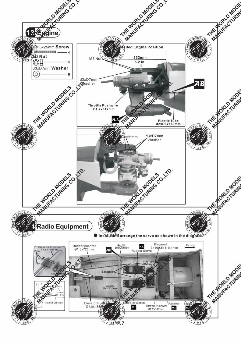
Engine13
8
PM 3x25mm Screw
M3 Nut
d3xD7mm Washer
4
8
Plastic Tubed2xD3x160mm
Installed Engine Position
132mm
5.2 in.M3 Nut
d3xD7mmWasher
PM 3x25mm d3xD7mmWasher
Throttle Pushwire
Ø1.2x312mm
14
Throttle Pushwire1.2x312mmØ
Elevator Servo
Sponge
FrontPlywood3x100.5x110.1mm
Rudder pushrodØ1.8x720mm
Elevator PushrodØ1.8x485mm
Rudder Servo
Straper
Install and arrange the servo as shown in the diagram.
Fuel Tube6x5mmØ
Fuel Tube6x5mmØ
KM 2x8mm
2mm
Elevator PushrodØ 1.8x145mm
BALSA6x6x95.5mm
BALSA6x6x95.5mm
Radio Equipment
Elevator Servo
Pushrod Connector BatteryReceiver
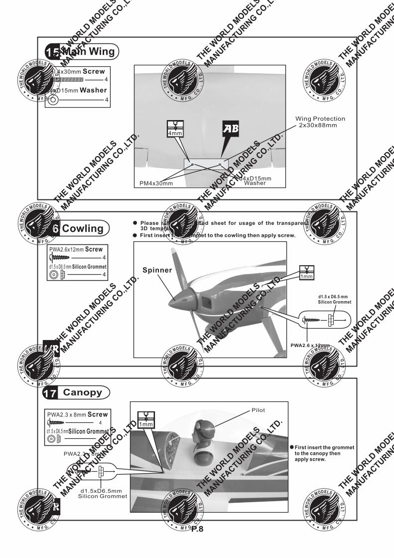
16 Cowling
PWA2.6x12mm Screw4
4
d1.5 x D6.5 mm Silicon Grommet
PWA2.6 x 12mm
Spinner
d1.5 x D6.5 mmSilicon Grommet
First insert the grommet to the cowling then apply screw.
1mm
Please refer to attached sheet for usage of the transparent3D template.
P.8
Canopy17
PWA2.3 x 8mm
d1.5xD6.5mmSilicon Grommet
1mm
Pilot
First insert the grommetto the canopy thenapply screw.
PWA2.3 x 8mm Screw
4
d1.5 x D6.5 mmSilicon Grommet
Wing Protection2x30x88mm
15
PM 4x30mm Screw
d4xD15mm Washer
4
4
PM4x30mm
4mm
Main Wing
d4xD15mmWasher
P.9
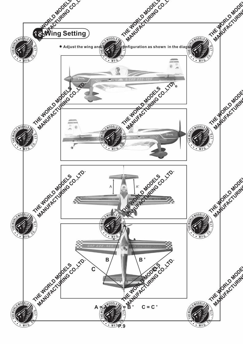
Wing Setting18
A = A ' B = B ' C = C '
Adjust the wing and fuselage configuration as shown in the diagrams.
B B '
C C '
A A'
P.10
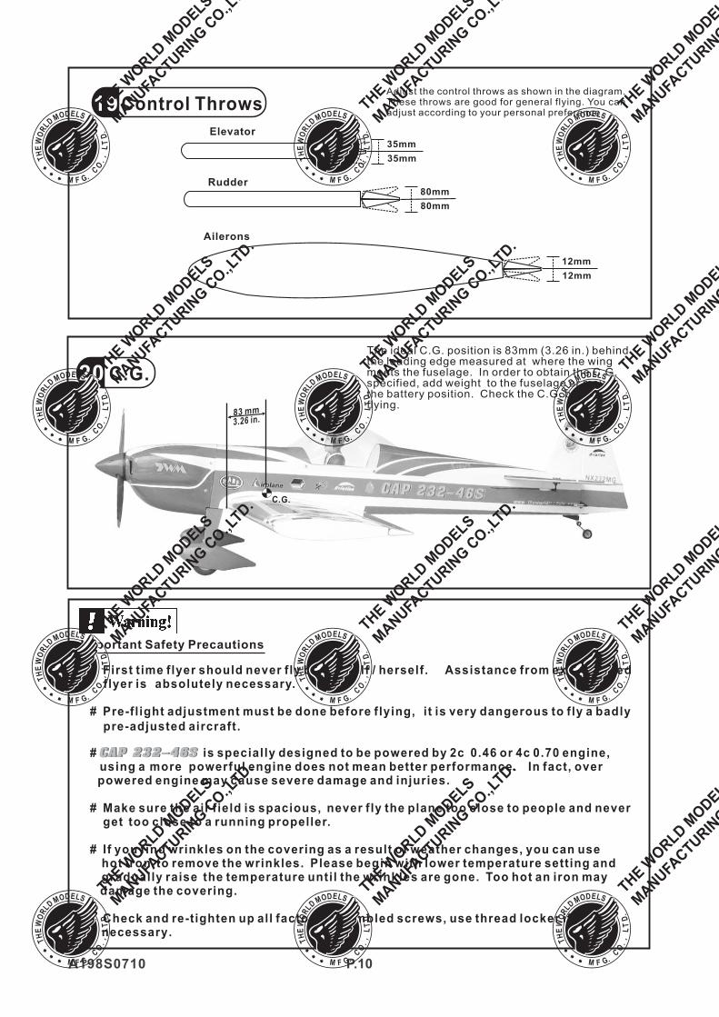
Control ThrowsAdjust the control throws as shown in the diagram.These throws are good for general flying. You canadjust according to your personal preference.
C.G.
Elevator
Rudder
19
20
Ailerons
12mm
80mm
80mm
35mm
35mm
Important Safety Precautions
# First time flyer should never fly by himself / herself. Assistance from experiencedflyer is absolutely necessary.
# Pre-fl ight adjustment must be done before flying, it is very dangerous to fly a badly
pre-adjusted aircraft.
# is specially designed to be powered by 2c 0.46 or 4c 0.70 engine,using a more powerful engine does not mean better performance. In fact, overpowered engine may cause severe damage and injuries.
# Make sure the air field is spacious, never fly the plane too close to people and neverget too close to a running propeller.
# If you find wrinkles on the covering as a result of weather changes, you can usehot iron to remove the wrinkles. Please begin with lower temperature setting andgradually raise the temperature until the wrinkles are gone. Too hot an iron maydamage the covering.
# Check and re-tighten up all factory assembled screws, use thread locker ifnecessary.
A198S0710
12mm
3.26 in.
C.G.
83 mm
The ideal C.G. position is 83mm (3.26 in.) behindthe leading edge measured at where the wingmeets the fuselage. In order to obtain the C.G.specified, add weight to the fuselage or movethe battery position. Check the C.G. beforeflying.
1
2 3
4
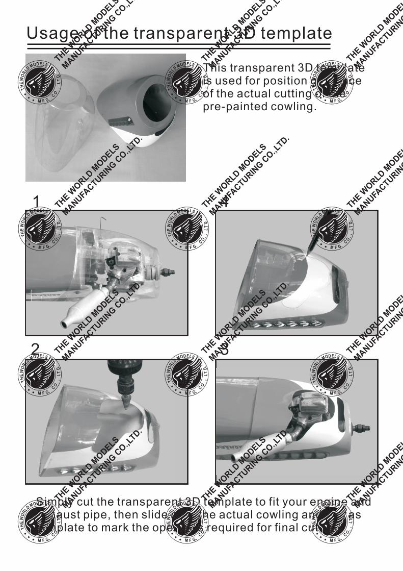
Usage of the transparent 3D template
This transparent 3D templateis used for position guidanceof the actual cutting of thepre-painted cowling.
Simply cut the transparent 3D template to fit your engine andexhaust pipe, then slide onto the actual cowling and use astemplate to mark the openings required for final cutting.
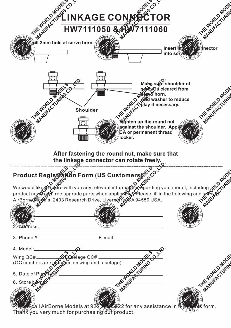
LINKAGE CONNECTOR
HW7111050 & HW7111060
After fastening the round nut, make sure thatthe linkage connector can rotate freely.
Drill 2mm hole at servo horn.
Insert linkage connectorinto servo horn.
Make sure shoulder ofscrew is cleared fromservo horn.Add washer to reduceplay if necessary.
Shoulder
Tighten up the round nutagainst the shoulder. ApplyCA or permanent threadlocker.
Product Registration Form (US Customers)
We would like to share with you any relevant information regarding your model, including
product news and free upgrade parts when applicable. Please fill in the following and send to
AirBorne Models, 2403 Research Drive, Livermore, CA 94550 USA.
1. Name:
2. Address:
3. Phone #: E-mail:
4. Model:
Wing QC# Fuselage QC#
(QC numbers are stamped on wing and fuselage)
5. Date of Purchase:
6. Store Name:
Please call AirBorne Models at 925 371 0922 for any assistance in filling this form.Thank you very much for purchasing our product.
http://www.theworldmodels.com


![MS11 - MSE11 - poclain-hydraulics.com · Potencia máx. cm³/rev [cu.in/rev]cm³/rev [cu.in/rev] kW [HP] favorables kW [HP] desfavorables ... Tapa de protección del freno cortada](https://static.fdocuments.net/doc/165x107/5bc1feb609d3f2a4318c3643/ms11-mse11-poclain-potencia-max-cmrev-cuinrevcmrev-cuinrev.jpg)
![MK35 - Poclain · Camme con Lobi Uguali Camme con Lobi Diversi Placca semplice A1 8 Placca rinforzata R1 8 ... [cu.in/rev.] cm³/giri [cu.in/rev.] 1 cilindrata 2 cilindrate. Motore](https://static.fdocuments.net/doc/165x107/5e537a1150960c098d7b69bb/mk35-poclain-camme-con-lobi-uguali-camme-con-lobi-diversi-placca-semplice-a1-8.jpg)


![MS11 - MSE11 - cohimec.com · Potencia máx. cm³/rev [cu.in/rev]cm³/rev [cu.in/rev] kW [HP] favorables kW [HP] desfavorables kW [HP] 1 cilindrada 2 cilindradas. 30/01/2013 3 ...](https://static.fdocuments.net/doc/165x107/5bc1feb609d3f2a4318c3645/ms11-mse11-potencia-max-cmrev-cuinrevcmrev-cuinrev-kw-hp.jpg)


