04.09061105(1)
10
Progress In Electromagnetics Research Letters, Vol. 10, 29–38, 2009 A NOVEL MINIATURE STRIP-LINE FED ANTENNA WITH BAND-NOTCHED FUNCTION FOR UWB APPLI- CATIONS S. Tu, Y. C. Jiao, Y. Song, and Z. Zhang National Laboratory of Antennas and Microwave Technology Xidian University Xi’an, Shaanxi 710071, P. R. China Abstract—A novel compact strip-line fed UWB antenna with band- notched characteristic is proposed. By employing a balanced antipodal structure and strip-line feed, the size of this antenna has been reduced to only 23 mm × 27.5 mm with the dielectric substrate of relative permittivity 2.65. Meanwhile, a slot is added onto the radiating patch of the mid metalisation layer to realize the band-notched function, by tuning the length of which suitable rejected frequency band can be obtained. According to the measured results, the proposed antenna has a large bandwidth totally satisfying the requirement of UWB applications (3.1 ∼ 10.6 GHz) with good stable omnidirectional radiation patterns and gains except in the rejected frequency band (4.9 ∼ 6.2 GHz). Details of this antenna are described, and the experimental results of the constructed prototype are given, too. 1. INTRODUCTION The ultra wideband (UWB) antennas provide high data transmission rate, low power consumption, and simple hardware configuration in communication applications such as RFID device, sensor net work, radar, and location tracking systems. Nevertheless, these systems are commonly required for the UWB antenna with compact size, low cost, and omnidirectional radiation [1]. In addition, to prevent the potential interference between the existing operating bands, such as WLAN (5.15 ∼ 5.825 GHz), band-notched function is appreciable and necessary for a good candidate UWB antenna. Corresponding author: S. Tu ([email protected]).
-
Upload
dhruvaaaaa -
Category
Documents
-
view
212 -
download
0
description
research document on patch antenna design
Transcript of 04.09061105(1)

Progress In Electromagnetics Research Letters, Vol. 10, 29–38, 2009
A NOVEL MINIATURE STRIP-LINE FED ANTENNAWITH BAND-NOTCHED FUNCTION FOR UWB APPLI-CATIONS
S. Tu, Y. C. Jiao, Y. Song, and Z. Zhang
National Laboratory of Antennas and Microwave TechnologyXidian UniversityXi’an, Shaanxi 710071, P. R. China
Abstract—A novel compact strip-line fed UWB antenna with band-notched characteristic is proposed. By employing a balanced antipodalstructure and strip-line feed, the size of this antenna has been reducedto only 23 mm × 27.5mm with the dielectric substrate of relativepermittivity 2.65. Meanwhile, a slot is added onto the radiatingpatch of the mid metalisation layer to realize the band-notchedfunction, by tuning the length of which suitable rejected frequencyband can be obtained. According to the measured results, the proposedantenna has a large bandwidth totally satisfying the requirement ofUWB applications (3.1 ∼ 10.6GHz) with good stable omnidirectionalradiation patterns and gains except in the rejected frequency band(4.9 ∼ 6.2GHz). Details of this antenna are described, and theexperimental results of the constructed prototype are given, too.
1. INTRODUCTION
The ultra wideband (UWB) antennas provide high data transmissionrate, low power consumption, and simple hardware configuration incommunication applications such as RFID device, sensor net work,radar, and location tracking systems. Nevertheless, these systemsare commonly required for the UWB antenna with compact size, lowcost, and omnidirectional radiation [1]. In addition, to prevent thepotential interference between the existing operating bands, such asWLAN (5.15 ∼ 5.825GHz), band-notched function is appreciable andnecessary for a good candidate UWB antenna.
Corresponding author: S. Tu ([email protected]).
30 Tu et al.
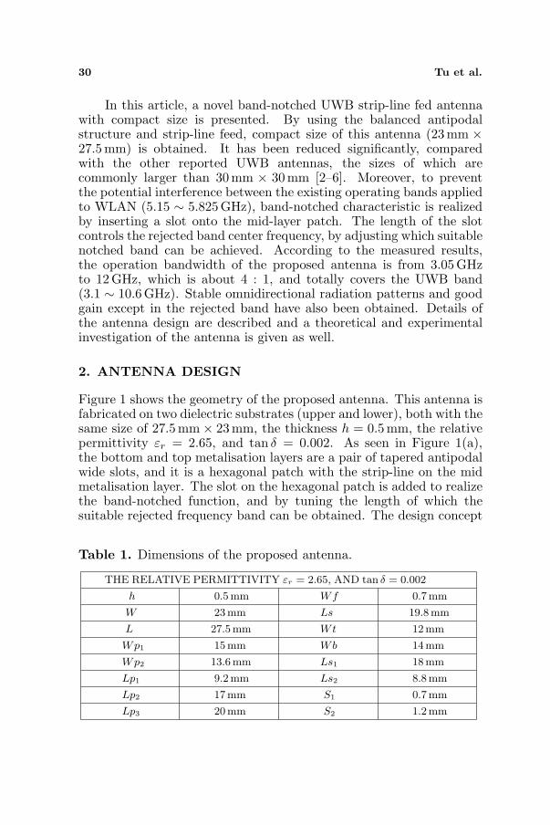
In this article, a novel band-notched UWB strip-line fed antennawith compact size is presented. By using the balanced antipodalstructure and strip-line feed, compact size of this antenna (23mm ×27.5mm) is obtained. It has been reduced significantly, comparedwith the other reported UWB antennas, the sizes of which arecommonly larger than 30 mm × 30mm [2–6]. Moreover, to preventthe potential interference between the existing operating bands appliedto WLAN (5.15 ∼ 5.825GHz), band-notched characteristic is realizedby inserting a slot onto the mid-layer patch. The length of the slotcontrols the rejected band center frequency, by adjusting which suitablenotched band can be achieved. According to the measured results,the operation bandwidth of the proposed antenna is from 3.05 GHzto 12GHz, which is about 4 : 1, and totally covers the UWB band(3.1 ∼ 10.6GHz). Stable omnidirectional radiation patterns and goodgain except in the rejected band have also been obtained. Details ofthe antenna design are described and a theoretical and experimentalinvestigation of the antenna is given as well.
2. ANTENNA DESIGN
Figure 1 shows the geometry of the proposed antenna. This antenna isfabricated on two dielectric substrates (upper and lower), both with thesame size of 27.5mm× 23mm, the thickness h = 0.5mm, the relativepermittivity εr = 2.65, and tan δ = 0.002. As seen in Figure 1(a),the bottom and top metalisation layers are a pair of tapered antipodalwide slots, and it is a hexagonal patch with the strip-line on the midmetalisation layer. The slot on the hexagonal patch is added to realizethe band-notched function, and by tuning the length of which thesuitable rejected frequency band can be obtained. The design concept
Table 1. Dimensions of the proposed antenna.
THE RELATIVE PERMITTIVITY εr = 2.65, AND tan δ = 0.002
h 0.5mm Wf 0.7mm
W 23mm Ls 19.8 mm
L 27.5mm Wt 12mm
Wp1 15mm Wb 14mm
Wp2 13.6mm Ls1 18mm
Lp1 9.2mm Ls2 8.8mm
Lp2 17mm S1 0.7mm
Lp3 20mm S2 1.2mm

Progress In Electromagnetics Research Letters, Vol. 10, 2009 31
(b)
(c)
(a)
Figure 1. Geometry of the proposed antenna: (a) Schematic diagram;(b) Configuration; (c) Fabrication antenna.

32 Tu et al.
of the notch function is to adjust the length of the embedded slots tobe about half-wavelength at the desired notched frequency making theinput impedance singular [7]. The variables of the designed antennasare marked in Figure 1(b). Since the top and bottom metalisationlayers are of the same configuration, dimensions of only one of themare presented. The fabrication antenna is shown in the Figure 1(c).Further, the optimized values of all variables are given in Table 1exactly.
3. SIMULATION AND EXPERIMENTAL RESULTS
To understand the behavior of the proposed antenna modal and obtainthe optimum parameters, the simulation was performed with AnsoftHFSS v11 except that the simulated radiation efficiency result wasobtained by CST Microwave Studio 2006, and the measurement wascarried out with a WILTRON37269A vector network analyzer afterfabricated. Figure 2 depicts the simulated and measured VSWRperformance of this antenna. It can be seen from the measuredresult that all frequency bands of UWB fulfill the requirement ofVSWR 5 2 other than 4.9–6.2 GHz which covers the WLAN band(5.15 ∼ 5.825GHz). There is an agreement between the measured andsimulated results.
Figure 3(a) indicates the simulated VSWR results for the proposedantenna in terms of diverse values Ls. The length of the slot added on
Figure 2. The comparison of the measured and simulated VSWRresults.

Progress In Electromagnetics Research Letters, Vol. 10, 2009 33
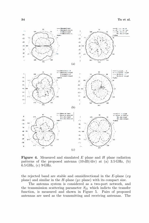
the hexagonal patch of the mid metalisation layer controls the centerfrequency of the notched band. It can be concluded from the resultsthat the rejected band can be easily adjusted by tuning the values ofLs with little influence on VSWR performance. Given the radiationpattern of this antenna, the symmetrical slot has been used to realizethe band-notched function, therefore the location of the slot is mainlydetermined by the parameter Lp2. Figure 3(b) displays the simulatedVSWR result in terms of different values Lp2, and Lp2 = 17 mm isfinally chosen in this design. The measured radiation patterns at3.5GHz, 6.5GHz and 9 GHz are presented in Figure 4, which indicatesthe radiation patterns of the proposed antenna at frequencies out of
(a)
(b)
Figure 3. Simulated VSWR results for the proposed antennarespectively in terms of (a) Ls and (b) Lp2; other parameters keepthe same as given in Table 1.
34 Tu et al.
(a)
(b)
(c)
Figure 4. Measured and simulated E plane and H plane radiationpatterns of the proposed antenna (10 dB/div) at (a) 3.5 GHz, (b)6.5GHz, (c) 9 GHz.
the rejected band are stable and omnidirectional in the E-plane (xyplane) and similar in the H-plane (yz plane) with its compact size.
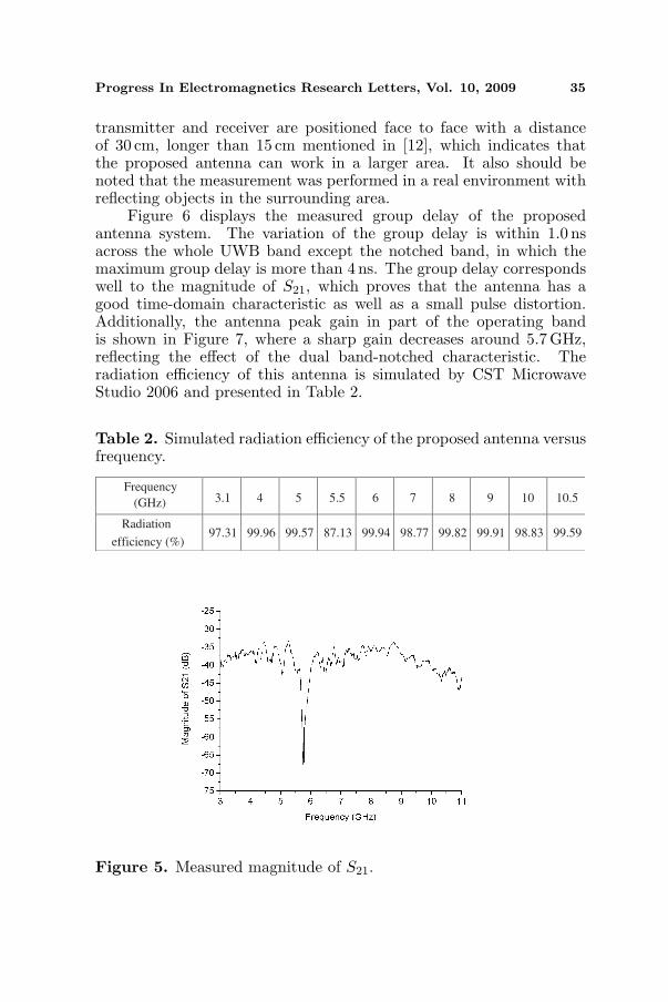
The antenna system is considered as a two-port network, andthe transmission scattering parameter S21 which indicts the transferfunction, is measured and shown in Figure 5. Pairs of proposedantennas are used as the transmitting and receiving antennas. The
Progress In Electromagnetics Research Letters, Vol. 10, 2009 35
transmitter and receiver are positioned face to face with a distanceof 30 cm, longer than 15 cm mentioned in [12], which indicates thatthe proposed antenna can work in a larger area. It also should benoted that the measurement was performed in a real environment withreflecting objects in the surrounding area.
Figure 6 displays the measured group delay of the proposedantenna system. The variation of the group delay is within 1.0 nsacross the whole UWB band except the notched band, in which themaximum group delay is more than 4 ns. The group delay correspondswell to the magnitude of S21, which proves that the antenna has agood time-domain characteristic as well as a small pulse distortion.Additionally, the antenna peak gain in part of the operating bandis shown in Figure 7, where a sharp gain decreases around 5.7 GHz,reflecting the effect of the dual band-notched characteristic. Theradiation efficiency of this antenna is simulated by CST MicrowaveStudio 2006 and presented in Table 2.
Table 2. Simulated radiation efficiency of the proposed antenna versusfrequency.
Radiation
efficiency (%)97.31 99.96 99.57 87.13 99.94 98.77 99.82 99.91 98.83 99.59
(GHz)
Frequency10.51098765.5543.1
Figure 5. Measured magnitude of S21.

36 Tu et al.
Figure 6. Measured group delay of the transfer system.
Figure 7. Measured peak gain of the proposed UWB antenna.
4. CONCLUSION
A novel miniature strip-line fed antenna with band-notched functionhas been demonstrated to exhibit UWB characteristics. A balancedantipodal structure and strip-line feed are utilized in this design toreduce the antenna size with sufficient matching band. Comparedwith most of the conventional UWB antennas, the size of the proposedantenna has been reduced significantly. Via inserting the slots onthe hexagonal patch of the mid metalisation layer, suitable band-
Progress In Electromagnetics Research Letters, Vol. 10, 2009 37
rejected characteristic can be realized. The measured results indicatethat the proposed UWB antenna not only owns stable good radiationpatterns and good gains, but also prevents interference from othercommunication systems.
REFERENCES
1. Zhang, L. N., S. S. Zhong, C. Z. Du, and J. H. Chen, “CompactUWB planar monopole antenna with band-notch function,”Microwave Opt. Technol. Lett., Vol. 51, 1908–1911, 2009.
2. Zhang, F., F. S. Zhang, G. Zhao, C. Lin, and Y. C. Jiao, “Anovel compact band-notched planar monopole antenna from 3 to40GHz,” Microwave Opt. Technol. Lett., Vol. 51, 1401–1403, 2009.
3. Zhang, G.-M., J.-S. Hong, and B.-Z. Wang, “Two novel band-notched UWB slot antennas fed by microstrip line,” Progress InElectromagnetics Research, PIER 78, 209–218, 2008.
4. Lin, C.-C. and H.-R. Chuang, “A 3–12 GHz UWB planartriangular monopole antenna with ridged ground-plane,” ProgressIn Electromagnetics Research, PIER 83, 307–321, 2008.
5. Gopikrishna, M., D. Das Krishna, C. K. Aanandan, P. Mohanan,and K. Vasudevan, “Design of a microstrip fed step slot antennafor UWB communication,” Microwave Opt. Technol. Lett., Vol. 51,1126–1129, 2009.
6. Zhou, H.-J, Y.-Z. Yin, J.-Y. Deng, Q.-Z. Liu, and Y.-C. Kan,“CPW-FED ultra-wideband antenna with dual band-notchedcharacteristics,” Microwave Opt. Technol. Lett., Vol. 51, 330–332,2009.
7. Chu, Q.-X. and Y.-Y. Yang, “3.5/5.5GHz dual band-notch ultra-wideband antenna,” Electron. Lett., Vol. 44, 172–174, 2008.
8. Lui, W. J., C. H. Cheng, and H. B. Zhu, “Compactbalanced antipodal slot antenna for ultra-wideband applications,”Microwave Opt. Technol. Lett., Vol. 48, 1943-1945, 2006.
9. Ren, W., Z. G. Shi, and K. S. Chen, “Novel planar monopoleUWB antenna with 5-GHz band notched characteristic,” Journalof Electromagnetic Waves and Applications, Vol. 21, No. 12, 1645–1652, 2007.
10. Chung, K., J. Kim, and J. Choi, “Wideband microstrip-fedmonopole antenna having frequency band-notched function,”IEEE Microwave and Wireless Components Letters, Vol. 15,No. 11, 766–768, Nov. 2005.

38 Tu et al.
11. Chu, Q.-X. and Y.-Y. Yang, “3.5/5.5GHz dual band-notch ultra-wideband antenna,” Electron. Lett., Vol. 44, 172–174, 2008.
12. Cho, Y. J., K. H. Kim, D. H. Choi, S. S. Lee, and S.-O. Park, “A miniature UWB planar monopole antenna with 5-GHz band-rejection filter and the time-domain characteristics,”IEEE Transactions on Antennas and Propagation, Vol. 54, No. 5,1453–1460, May 2006.

![[XLS]fmism.univ-guelma.dzfmism.univ-guelma.dz/sites/default/files/le fond... · Web view1 1 1 1 1 1 1 1 1 1 1 1 1 1 1 1 1 1 1 1 1 1 1 1 1 1 1 1 1 1 1 1 1 1 1 1 1 1 1 1 1 1 1 1 1 1](https://static.fdocuments.net/doc/165x107/5b9d17e509d3f2194e8d827e/xlsfmismuniv-fond-web-view1-1-1-1-1-1-1-1-1-1-1-1-1-1-1-1-1-1-1-1-1-1.jpg)
![1 1 1 1 1 1 1 ¢ 1 1 1 - pdfs.semanticscholar.org€¦ · 1 1 1 [ v . ] v 1 1 ¢ 1 1 1 1 ý y þ ï 1 1 1 ð 1 1 1 1 1 x ...](https://static.fdocuments.net/doc/165x107/5f7bc722cb31ab243d422a20/1-1-1-1-1-1-1-1-1-1-pdfs-1-1-1-v-v-1-1-1-1-1-1-y-1-1-1-.jpg)

![[XLS] · Web view1 1 1 2 3 1 1 2 2 1 1 1 1 1 1 2 1 1 1 1 1 1 2 1 1 1 1 2 2 3 5 1 1 1 1 34 1 1 1 1 1 1 1 1 1 1 240 2 1 1 1 1 1 2 1 3 1 1 2 1 2 5 1 1 1 1 8 1 1 2 1 1 1 1 2 2 1 1 1 1](https://static.fdocuments.net/doc/165x107/5ad1d2817f8b9a05208bfb6d/xls-view1-1-1-2-3-1-1-2-2-1-1-1-1-1-1-2-1-1-1-1-1-1-2-1-1-1-1-2-2-3-5-1-1-1-1.jpg)

![1 1 1 1 1 1 1 ¢ 1 , ¢ 1 1 1 , 1 1 1 1 ¡ 1 1 1 1 · 1 1 1 1 1 ] ð 1 1 w ï 1 x v w ^ 1 1 x w [ ^ \ w _ [ 1. 1 1 1 1 1 1 1 1 1 1 1 1 1 1 1 1 1 1 1 1 1 1 1 1 1 1 1 ð 1 ] û w ü](https://static.fdocuments.net/doc/165x107/5f40ff1754b8c6159c151d05/1-1-1-1-1-1-1-1-1-1-1-1-1-1-1-1-1-1-1-1-1-1-1-1-1-1-w-1-x-v.jpg)


![1 $SU VW (G +LWDFKL +HDOWKFDUH %XVLQHVV 8QLW 1 X ñ 1 … · 2020. 5. 26. · 1 1 1 1 1 x 1 1 , x _ y ] 1 1 1 1 1 1 ¢ 1 1 1 1 1 1 1 1 1 1 1 1 1 1 1 1 1 1 1 1 1 1 1 1 1 1 1 1 1 1](https://static.fdocuments.net/doc/165x107/5fbfc0fcc822f24c4706936b/1-su-vw-g-lwdfkl-hdowkfduh-xvlqhvv-8qlw-1-x-1-2020-5-26-1-1-1-1-1-x.jpg)