
04 - 2014 POWERCIAT2 - CIAT - warmtepompen, koelsystemen ...
42
POWERCIAT2 LX - LXC AQUACIAT 2 Instruction manual 04 - 2014 N 13.47 B
Transcript of 04 - 2014 POWERCIAT2 - CIAT - warmtepompen, koelsystemen ...
POW
ERCI
AT2
LX -
LXC
AQU
ACIA
T 2
Ins t ruc t ion manua l
04 - 2014
N 13.47 B


EN
EN - 1 NA13.47 B
ORIGINAL TEXT: ENGLISH VERSION
SOMMAIRE PAGE
1. GENERAL INFORMATION 21.1 Intended use 2
1.2 Documentation 2
1.3 Warranty 2
2. SAFETY INSTRUCTIONS 2
3. REGULATIONS 23.1 General information 2
3.2 Applicable standards and directives 2
3.3 Accreditation 2
3.4 Pressure and temperature 2
3.5 Refrigerants 2
4. IDENTIFICATION 34.1 Data plate 3
5. DESCRIPTION 35.1 Main components 3
5.2 Hydraulic circuit (POWERCIAT2 LXC) 4
5.3 Location of the main components 5
6. SPECIFICATIONS 66.1 STD technical specifications 6
6.2 HEE technical specifications 7
6.3 Electrical specifications 8
6.4 Electrical specifications 9
6.5 Hydraulic pump specifications 9
6.6 Sensor specifications 9
6.7 Operating limits 10
7. DELIVERY - HANDLING 137.1 Delivery 13
7.2 Lorry shipment: 13
7.3 Container shipment: 13
7.4 Lifting instructions 13
7.5 Anchoring points for handling 13
8. INSTALLATION 158.1 Warning for the installer 15
8.2 Selecting a location 15
8.3 Water quality 15
8.4 Sound level 15
8.5 Frost protection 15
8.6 Location 17
8.7 Anti-vibration mounts for STD models (optional) 18
8.8 Anti-vibration mounts for HEE models (optional) 22
9. CONNECTIONS 269.1 Assembling the hydraulic module 26
9.2 Hydraulic connections 26
9.3 LX - LXC series desuperheater exchanger 26
9.4 Specifications of the hydraulic connections 27
9.5 Electrical connections 28
10. CONTROL 2810.1 Control principle 28
10.2 Xtraconnect 2 control module 28
10.3 Master/Slave control 28
10.4 Control and safety devices 29
11. SYSTEM START-UP 3011.1 Preliminary checks 30
11.2 Starting up the compressors 30
11.3 Starting up the unit 30
11.4 Post-start-up checks 30
12. USE 3212.1 Recommendations for use 32
12.2 Prolonged stoppages 32
13. MAINTENANCE 3313.1 Recommendations for maintenance 33
13.2 Preventive maintenance 33
13.3 Corrective maintenance 34
14. PERMANENT SHUTDOWN 3514.1 Decommissioning 35
14.2 Dismantling recommendations 35
14.3 Fluids to be recovered for treatment 35
14.4 Materials to be recovered for recycling 35
14.5 Waste Electrical and 35
Electronic Equipment (WEEE) 35
15. OPERATING READINGS 36

NA13.47 B EN - 2
� Before carrying out any work on the unit, make sure it is powered off.
� Only experienced, qualified technicians may work on the machine. They must have all the necessary Personal Protective Equipment (PPE): glasses, gloves, safety shoes and hearing protection.
� To prevent the risk of accidents, you must take into account the specific features of the product throughout its life cycle, in particular: - pressurised hydraulic circuits containing a glycol/water mix; - pressurised refrigeration circuits containing refrigerant; - presence of voltage.
� Thank you for choosing the POWERCIAT2 water chiller. Your machine has been designed and manufactured using all the expertise of CIAT's teams of technicians and refrigeration specialists.
1.1 Intended use � POWERCIAT2 LX and LXC models are air-cooled
condensation water chillers designed to produce chilled water.
� Your machine should not be operated under more demanding conditions than those defined by the study, particularly in terms of pressures, temperatures, flow rates, fluid nature and direction of circulation etc. These conditions are defined in the order contract.
1.2 Documentation � This manual contains all of the operating instructions
for your machine. Before carrying out any work on the
machine, please read all of the instructions and make sure you have all the necessary documentation. This manual must be kept in the immediate vicinity of the unit. It does not cover the entire installation.
� For more details about the installation and commissioning phases, please also refer to: - the order documents - the technical manual - the dimensional drawing - the delivery note - the wiring diagram(s) - the refrigerating diagram - the individual manuals for any accessories - the Xtraconnect 2 control module manual - the labels affixed to the unit
1.3 Warranty � See general terms and conditions of sale.
3.1 General information � All POWERCIAT2 units are tested and checked in the
factory. They are supplied with a full refrigerant charge. � In addition to this manual, please comply with the regulations and
legislation in force on the work site. � Any modifications or welding to pressurised parts is
dangerous and may be prohibited by regulations. � This unit is not required to withstand earthquakes. Earthquake
resistance has therefore not been checked.
3.2 Applicable standards and directives � CIAT water chillers comply with:
EUROPEAN DIRECTIVES - Machinery 2006/42/EC - EMC 2004/108/EC - Low voltage 2006/95/EC - PED 97/23/EC Category 3 (2500 to 3900 HEE models,
2800 to 4800 STD models) and category 4 (4200 to 4800 HEE models & 5600 and 6400 STD models)
- WEEE 2012/19/EU - RoHS 2011/65/EU
CE REGULATIONS - REACH 1907/2006
HARMONISED STANDARDS - EN 60204 and EN 378-2
3.3 Accreditation � The following accreditation is required to work on the unit:
- on chillers or any other system using refrigerants: accreditation for work with refrigerant in accordance with regulations;
- on or near electrical components: electrician accreditation in accordance with regulations.
� Technicians who install, commission, operate and service the unit must possess the necessary training and certifications, understand the instructions given in this manual and be familiar with the specific technical characteristics of the installation site.
� Any work on the refrigeration circuit must meet the requirements of EC regulation no. 842/2006.
3.4 Pressure and temperature � Test pressure (TP): In accordance with § 5.3.2.2 a
and 6.3.3 iii of standard 378-2, the pressure test (PT) is performed on model representative of all 3 x PS assemblies.
� Shipping temperature: min.: -20°C., max.: +65°C. � Storage temperature: -20°C., max.: +65°C. � Operating temperature: see § OPERATING RANGES.
3.5 Refrigerants � In accordance with EC regulation no. 842/2006 concerning
certain greenhouse gases, the environmental impact of R410A, R134a and R407C fluids is: - on the OZONE layer: NONE. ODP (Ozone Depletion
Potential) rating = 0 - on the greenhouse effect (GWP = Global Warming
Potential: - R410A: GWP=2088 - R407C: GWP=1800 - R134a: GWP=1430
� Users must have a sealing check carried out by a qualified technician. The frequency is determined by the refrigerant charge: - every 12 months for units containing 3 to 30 kg of
refrigerant. (2 kg in France, edict and decree of 7 May 2007);
- every 6 months for units containing 30 to 300 kg of refrigerant;
- every 3 months for units containing over 300 kg of refrigerant (a leak detection system must be installed).
� Users of any system containing over 3 kg of refrigerant (2 kg in France) are required to keep a log of the quantities and types of refrigerants used, added or recovered, and to include the dates and results of leak tests, as well as the name of the technician and company performing the test.
� A sealing check must be carried out one month after any repairs to a circuit containing refrigerant.
� System users are responsible for collecting used refrigerant and having it recycled, regenerated or destroyed.
1. GENERAL INFORMATION
2. SAFETY INSTRUCTIONS
3. REGULATIONS

EN
EN - 3 NA13.47 B
� Data: - Désignation (Description): Type POWERCIAT2 - An (Year) : Year of manufacture - N° série (Serial No): number to be quoted in all
correspondence - Type refrigerant: type of refrigerant - Qty refrigerant kg: refrigerant content in kg - BP(LP): P.MIN / PS: For the low pressure circuit:
P. MIN = minimum operating pressure in bar PS = Maximum authorised pressure in bar (PS in accordance with PED 97/23/EC)
- HP(HP): P.MAX / PS: For the high pressure circuit: P. MAX = maximum operating pressure in bar PS = Maximum authorised pressure in bar (PS in accordance with PED 97/23/EC)
- P.Abs (P.Input): Power input in kW - Tension (Voltage): Power supply - Intensité (Current): Rated current in A - P. test (Test pressure): see § "Pressure and temperature" - Masse (Weight): Operating weight of the unit in kg - Temperatures Min/Max: see § "Pressure and temperature" - IP: Machine protection rating - N° CE: Notified Body number
)traP( erepeR)rN laireS( eirés °N)raeY(nA~1000\13708023102
Type refrigerant P.Abs (P.Input) Masse (Mass)223 KW
Qty refrigerant kg Tension (Voltage)3 50HZ 400V
BP(LP) : P.MIN / PS Intensité (Current)464 A
HP(HP) : P.MAX / PS P. test (Test pressure) N° CEPT=3XPS CF. MANUEL
Ref. produit (Item Ref.) Designation (Description)3025282.123 LX 2800X-STD R134A
N° Produit (Item Nr)
GK 0835A431R
0600RAB82 / RAB5.02
Temperatures Min/MaxLEUNAM .FC84+84
IP44RAB91 / RAB3.0
5.1 Main components
Compressors � POWERCIAT2 units use accessible hermetic compact
screw compressors.
Oil � The oil contained in the compressor is used both for
lubrication and dynamic sealing of the space between the rotors. Its solubility, viscosity and foam formation characteristics therefore must be respected. Only use recommended oil: Bitzer polyester (POE) BSE 170.
RefrigerantPOWERCIAT2 units use R134a.
Exchangers � The evaporators are shell and tube type exchangers.
They are insulated with 10 mm thick polyurethane foam as standard. In its standard configuration, the shell and tube exchanger is only designed to operate with clean, non-corrosive fluids such as pure water, soft water, monoethylene glycol or monopropylene glycol. Fluids such as brackish water, seawater and demineralised water require a specialised design. We recommend filtering the energy transfer fluid.
� No repairs or modifications are permitted on the evaporator. Only replacement of the heat exchanger with another original heat exchanger and by a qualified technician is authorised. If the heat exchanger is replaced, this must be noted in the maintenance booklet.
� The maximum authorised pressure (PS) in the hydraulic circuit is 10 bar.
Electronic expansion valve � Each unit is fitted with one-piece hermetically-sealed
electronic expansion valves that are set in the factory to maintain superheat of 5-7°C under all operating conditions.
Filter dryer � Each unit is fitted as standard with a filter dryer to keep the
refrigerating circuit clean and free of moisture. The filter dryers consist of a molecular sieve that neutralises any acids in the refrigeration circuit.
Liquid sight glass � Located on the liquid line just after the filter dryer, the liquid
sight glass is used to monitor the charge in the unit and to check for moisture in the circuit. Bubbles in the sight glass mean that the refrigerant charge is insufficient or that non-condensable gases are present in the refrigerating circuit. If the sight glass indicator paper changes colour, there is moisture in the circuit.
� Some of the sight glasses may turn yellow when the machine is powered off as their sensitivity is affected by
the fluid temperature. These should return to green after the unit has been operating for a few hours. If the sight glasses remain yellow, there is excessive moisture in the circuit. A specialist intervention is required.
4.1 Data plate � Each POWERCIAT2 unit has a manufacturer's data plate
bearing the unit's identification number and description. Make sure this information matches that on the order.
5. DESCRIPTION
� Markings (data plate, punch marks, labels) must remain visible. They must not be altered, removed or modified.
� Please include the identification number in all correspondence with CIAT.
4. IDENTIFICATION

NA13.47 B EN - 4
FSB1
MS
RE
RT
1
2
1MSMS
MS
�
� �
�
�
�
� �
�
A
D
CB
RMHB18
5.2 Hydraulic circuit (POWERCIAT2 LXC)Schematic diagram (buffer tank optional).The 80-litre expansion vessels are pressurised to 1.5 bar.
ValvePressure sensor (optional)Pressure gaugeShut-off butterfly valveFilter (to be installed on site)Heat-insulated component
� : Customer connection - Water inlet� : Automatic bleed valve : Manual valve� : 1.5 bar expansion vessel - Hose connection� : 4 bar safety valve� : Water drain valve� : Customer connection - Water outlet�: Flexible coupling kitRMH: Hydraulic module heater (optional)
MS: Flexible couplingRE/RT: Heating cables (optional)FS: Flow rate controllerB1: External sensorB18: Hydraulic module indoor environment sensor
A: EVAPORATORB: TANK (option)C: SINGLE PUMPD: DOUBLE PUMP
POWERCIAT2 "LXC"
� Based on the POWERCIAT2 LX, LXC models incorporate a complete hydraulic assembly in a connected module: - 1 single-cell centrifuge hydraulic pump with
pressure gauge(s) (single or double pump).NB: our pumps are designed to operate on a closed water loop. Please consult us for other applications (open water loop, high NPSH, etc.);
- 1 expansion vessel; - 1 automatic air bleed valve; - 1 safety valve;
- 1 drain hole with valve; - 1 set of pump shut-off valves; - 1 pump inlet pressure sensor (optional). If the suction
pressure is less than 1 bar, the unit cannot be started. - 1 optional 900-litre insulated buffer tank which requires
an additional module connected to the hydraulic module.
- The maximum authorised pressure on the water side is 4 bar.

EN
EN - 5 NA13.47 B
5.3 Location of the main components
A: End electrical cabinetB: Fan motor assembliesC: CompressorD: Centre electrical cabinet
E: EvaporatorF: Expansion vesselG: PumpH: Buffer tank
LX(C) 5600X STD - 6400X STD - 4200X HEE - 4500X HEE - 4800X HEEA C D GC HEB F
LX(C) 4200X STD - 4800X STD - 3200X HEE - 3400X HEE - 3600X HEE - 3900X HEEA C D GC HB E F
LX(C) 3200X STD - 3400X STD - 3600X STD - 2800X HEE - 3050X HEEA HGCB E F
LX(C) 2800X STD - 3000X STD - 2500X HEEA HGFCB E

NA13.47 B EN - 6
6. SPECIFICATIONS6.1 STD technical specifications
POWERCIAT2 LX-LXC STD 2800X 3000X 3200X 3400X 3600X 4200X 4800X 5600X 6400X
Standard version
Net cooling capacity (1) kW 667 723 792 840 891 1049 1156 1269 1355Net power input (2) kW 227 250 266 282 299 345 390 426 470net EER/ESEER 2.94/3.55 2.9/3.5 2.98/3.58 2.98/3.59 2.98/3.6 3.04/3.64 2.96/3.56 2.98/3.58 2.88/3.47Lw / Lp (3) dB(A) 100/67 100/67 101/68 101/68 101/68 102/69 102/69 103/70 103/70
Low Noise/ Xtra Low
Noise version
Net cooling capacity (1) kW 659 711 782 829 877 1036 1138 1252 1334Net power input (2) kW 226 251 265 283 300 343 394 425 472net EER/ESEER 2.91/3.82 2.83/3.72 2.95/3.84 2.93/3.82 2.92/3.82 3.02/3.91 2.89/3.75 2.95/3.83 2.83/3.69Lw / Lp Low Noise (3) dB(A) 96/63 96/63 97/64 97/64 97/64 98/65 98/65 99/66 99/66Lw / Lp Xtra Low Noise (3) dB(A) 93/60 93/60 94/61 94/61 94/61 95/62 95/62 96/63 96/63
Refrigeration circuit
Refrigerant (GWP) R134a (1430)Quantity 2Refrigerant circuit 1 kg 49 57 61 76 76 93 101 112 112Refrigerant circuit 2 kg 48 48 59 59 74 80 88 91 94
Compressor
Type Double-screw accessible hermeticQuantity 2Rotation speed rpm 2900Power control % Continuous from 25 to 100% (50 to 100% on each compressor) Type of oil for R134a BITZER BSE 170Oil capacity circuit 1 litres 19 30 30 30 30 30 30 32 32Oil capacity circuit 2 litres 19 19 30 30 30 30 30 30 32
Evaporator
Type Dry expansion shell and tubeQuantity 1Water content litres 240 283 443 560
Hydraulic connection Flexible COLLAR DN 200 Flexible COLLAR DN 250
Max. pressure, water end bar 10���������� �� m3/h 71/241 77/241 83/241 90/241 96/241 111/241 124/241 136/383 145/383
Air-cooled condenser
Fans Direct-drive axial - diameter 910 mmNumber of fans 12 14 18 22Rotation speed rpm STANDARD VERSION: 910 rpm�� �� ��� m3/h 264 000 308 000 396 000 484 000Motor output (per motor) kW 1,8Rotation speed rpm LOW NOISE - XTRA LOW NOISE 720 rpm versions�� �� ��� m3/h 198 000 231 000 297 000 363 000Motor output (per motor) kW 1,2
Hydraulic module (Option)
Expansion vessel capacity litres 80Max. pressure, water end bar 4Tank capacity (option) litres 900
Dimensions
Length LX version mm 6506 7592 9756 11928Length LXC version mm 7598 8684 10848 13020Length LXC version + Buffer tank 8690 9776 11940 14112Width mm 2251Height mm 2435
Weight (empty)*
LX version kg 5196 5612 6558 6591 6618 7843 7867 9334 9508LXC version kg 6378 6793 7766 7798 7826 9036 9060 10562 10736LXC version + Buffer tank kg 7015 7430 8403 8435 8463 9673 9697 11199 11373
Operating weight*
LX version kg 5436 5852 6841 6873 6901 8278 8302 9889 10067LXC version kg 6762 7177 8197 8229 8256 9612 9636 11292 11470LXC version + Buffer tank kg 8391 8807 9810 9842 9869 11234 11258 12914 13091
(*) Without compressor sound box. Box weights = 2 x 150 kg(1) Net cooling capacity for chilled water temperature 12°C/7°C and condenser air inlet temperature 35°C - as per EN 14511 conditions(2) Net power input - compressors + fans(3) Lw: Overall power level as per standard ISO 3744
Lp: Overall pressure level measured at 10m in a free field, calculated using the formula Lp = Lw - 10logS

EN
EN - 7 NA13.47 B
6.2 HEE technical specificationsPOWERCIAT2 LX-LXC HEE 2500X 2800X 3050X 3200X 3400X 3600X 3900X 4200X 4500X 4800X
Standard version
Net cooling capacity (1) kW 613 683 750 817 871 924 980 1061 1116 1170Net power input (2) kW 201 223 245 264 277 291 315 341 359 379net EER/ESEER 3.04/3.67 3.06/3.69 3.06/3.69 3.09/3.73 3.14/3.79 3.18/3.84 3.11/3.75 3.11/3.75 3.11/3.75 3.09/3.73Lw / Lp (3) dB(A) 100/67 101/68 101/68 102/69 102/69 102/69 102/69 103/70 103/70 103/70
Low Noise/ Xtra Low
Noise version
Net cooling capacity (1) kW 606 681 743 816 866 919 970 1056 1109 1161Net power input (2) kW 197 217 242 254 269 284 312 331 352 374net EER/ESEER 3.07/4.00 3.13/4.08 3.07/4.00 3.21/4.19 3.22/4.20 3.24/4.22 3.11/4.06 3.19/4.16 3.15/4.11 3.11/4.06Lw / Lp Low Noise (3) dB(A) 96/63 96/63 97/64 97/64 98/65 98/65 98/65 99/66 99/66 99/66Lw / Lp Xtra Low Noise (3) dB(A) 90/57 91/58 91/58 92/59 92/59 92/59 92/59 96/60 96/60 93/60
Refrigeration circuit
Refrigerant (GWP) R134a (1430)Quantity 2Refrigerant circuit 1 kg 44 54 76 66 84 84 93 101 109 109Refrigerant circuit 2 kg 43 51 46 65 65 79 79 83 83 91
Compressor
Type Double-screw accessible hermeticQuantity 2Rotation speed rpm 2900Power control % Continuous from 25 to 100% (50 to 100% on each compressor) Type of oil for R134a BITZER BSE 170Oil capacity circuit 1 litres 19 19 30 30 30 30 30 30 30 30Oil capacity circuit 2 litres 19 19 19 30 30 30 30 30 30 30
Evaporator
Type Dry expansion shell and tubeQuantity 1Water content litres 240 283 443 560
Hydraulic connectionLX Flexible COLLAR DN 200 Flexible COLLAR 250
LXC Flexible COLLAR DN200Max. pressure, water end bar 10���������� �� m3/h 63/241 70/241 77/241 83/241 89/241 95/241 101/241 109/383 115/383 121/383
Air-cooled condenser
Fans Direct-drive axial - diameter 910 mmNumber of fans 12 14 18 22Rotation speed rpm STANDARD VERSION: 910 rpm�� �� ��� m3/h 264 000 308 000 396 000 484 000Motor output (per motor) kW 1,8Rotation speed rpm LOW NOISE VERSION - 720 rpm�� �� ��� m3/h 198 000 231 000 297 000 363 000Motor output (per motor) kW 1,2
Hydraulic module (Option)
Expansion vessel capacity litres 80Max. pressure, water end bar 4Tank capacity (option) litres 900
Dimensions
Length LX version mm 6506 7592 9756 11928Length LXC version mm 7598 8684 10848 13020Length LXC version + Buffer tank 8690 9776 11940 14112Width mm 2251Height mm 2435
Weight (empty)*
LX version kg 5159 5731 6166 7782 7795 7813 7900 9123 9136 9148LXC version kg 6341 6939 7374 8975 8988 9006 9093 10351 10364 10376LXC version + Buffer tank kg 6978 7576 8011 9612 9625 9643 9730 10988 11001 11013
Operating weight*
LX version kg 5400 6014 6450 8216 8230 8250 8336 9683 9696 9708LXC version kg 6726 7370 7806 9550 9564 9584 9670 11086 11099 11111LXC version + Buffer tank kg 8355 8983 9419 11172 11185 11206 11292 12708 12721 12733
(*) without compressor sound box. Box weights = 2 x 150 kg(1) Net cooling capacity for chilled water temperature 12°C/7°C and condenser air inlet temperature 35°C - as per EN 14511 conditions(2) Net power input - compressors + fans(3) Lw: Overall power level as per standard ISO 3744
Lp: Overall pressure level measured at 10m in a free field, calculated using the formula Lp = Lw - 10logS

NA13.47 B EN - 8
6.3 Electrical specificationsPOWERCIAT2 LX-LXC STD 2800X 3000X 3200X 3400X 3600X 4200X 4800X 5600X 6400X
COMPRESSORS (1)
Maximum rated current A 418 (2 x 209)
447 (238 + 209)
476 (2 x 238)
497 (259 + 238)
518 (2 x 259)
612 (2 x 306)
682 (2 x 341)
756 (415 + 341)
830 (2 x 415)
Star-Delta starting current (3) A 473 568 609 638 637 785 872 1139 1182
FAN MOTORS (1)
STANDARD VERSION: 910 rpm
Maximum rated current A 46 53,6 68,9 84,3
LOW NOISE - XTRA LOW NOISE 720 rpm VERSION
Maximum rated current A 26,6 31,1 40 48,8
LX FROST PROTECTION (OPTION) (1)
Evaporator heating element capacity W 320 640
Maximum rated current A 0,8 1,6
LXC FROST PROTECTION (OPTION) (1)
Evaporator + piping heating element capacity W 500 820
Maximum rated current A 1,3 2,1
Pump module heating element capacity W 1500
Maximum rated current A 3,8
LXC FROST PROTECTION + BUFFER TANK (OPTION) (1)
Evaporator + piping heating element capacity W 500 820
Maximum rated current A 1,3 2,1
Pump module + tank heating element capacity W 2 x 1500
Maximum rated current A 2 x 3.8
DESUPERHEATER FROST PROTECTION (OPTION) (1)
Heat exchanger heating element power W 240 (2 x 120)
Maximum rated current A 0.6 (2 x 0.3)
REMOTE CONTROL AUXILIARY CIRCUIT (2)
Maximum rated current A 4 8
Transformer capacity VA 1000 1600
Machine protection rating IP44
(1) Current for voltage 400V/3Ph/50Hz (+/-10%)(2) Current for voltage 230V/1Ph/50Hz (+/-10%)(3) Starting current of largest compressor + maximum current of other compressors at 50% load.Cable selection rated current = sum of maximum rated currents in above tables.

EN
EN - 9 NA13.47 B
6.4 Electrical specificationsPOWERCIAT2 LX-LXC HEE 2500X 2800X 3050X 3200X 3400X 3600X 3900X 4200X 4500X 4800X
COMPRESSORS (1)
Maximum rated current A 374 (2 x 187)
418 (2 x 209)
446(259 + 187)
476 (2 x 238)
497 (259+ 238)
518 (2 x 259)
565(306 +259)
612 (2 x 306)
647 (341+306)
682 (2 x 341)
Star-Delta starting current (3) A 436 473 587 609 638 637 758 785 849 872
FAN MOTORS (1)
STANDARD VERSION: 910 rpm
Maximum rated current A 46 53,6 68,9 84,3
LOW NOISE - XTRA LOW NOISE 720 rpm VERSION
Maximum rated current A 26,6 31,1 40 48,8
LX FROST PROTECTION (OPTION) (1)
Evaporator heating element capacity W 320 640
Maximum rated current A 0,8 1,6
LXC FROST PROTECTION (OPTION) (1)
Evaporator + piping heating element capacity W 500 820
Maximum rated current A 1,3 2,1
Pump module heating element capacity W 1500
Maximum rated current A 3,8
LXC FROST PROTECTION + BUFFER TANK (OPTION) (1)
Evaporator + piping heating element capacity W 500 820
Maximum rated current A 1,3 2,1
Pump module + tank heating element capacity W 2 x 1500
Maximum rated current A 2 x 3.8
DESUPERHEATER FROST PROTECTION (OPTION) (1)
Heat exchanger heating element power W 240 (2 x 120)
Maximum rated current A 0.6 (2 x 0.3)
REMOTE CONTROL AUXILIARY CIRCUIT (2)
Maximum rated current A 4 8
Transformer capacity VA 1000 1600
Machine protection rating IP44
(1) Current for voltage 400V/3Ph/50Hz (+/-10%)(2) Current for voltage 230V/1Ph/50Hz (+/-10%)(3) Starting current of largest compressor + maximum current of other compressors at 50% load.Cable selection rated current = sum of maximum rated currents in above tables.
6.5 Hydraulic pump specificationsSINGLE PUMPS (LXC ONLY) (1)
Number 111 113 114 115 116
Power kW 11 15 18.5 22 30
Maximum rated current A 20 26.5 32.5 39 53
DOUBLE PUMPS (LXC ONLY) (1)
Number 211 213 214 215 216
Power kW 11 15 18.5 22 30
Maximum rated current A 20 26.5 32.5 39 53
(1) Current for voltage 400 V/3Ph/50 Hz
6.6 Sensor specifications
Temperature sensors
Temperature (°C) -10 -5 0 5 10 15 20 25 30 35 40 45 50
Sens
or
resis
tanc
e in
�
Sensor 50 k� 276 061 210 694 162 213 125 779 98 322 77 454 61 465 49 120 39 517 31 996 26 065 21 358 17 599
Sensor 10 k� 55 150 42 250 32 630 25 390 19 910 15 720 12 500 10 000 8 054 6 527 5 321 4 363 3 597

NA13.47 B EN - 10
6.7 Operating limits
6.7.1 Operating ranges
A: Full load operation with pure waterB: Full load operation must be with glycolC: Operation without economiser
Partial load operation for outdoor temperature > 48°C
AB
C
-15
+20
-10
0
+10
+30
-8 +5 +15+10+80-6
+45+48
+40
Out
door
tem
pera
ture
(°C
) D
B
Evaporator water outlet (°C)
Glycol obligatory
� STANDARD (STD) version
� Low Noise Version (STD LN ) - Xtra Low Noise Version (STD XLN)
AB
C
-15
+20
-10
0
+10
+30
-8 +5 +15+100-6
+44+47
+40
Partial load operation for outdoor temperature > 47°C
Evaporator water outlet (°C)
Out
door
tem
pera
ture
(°C
) D
B
Glycol obligatory
A: Full load operation with pure waterB: Full load operation must be with glycolC: Operation without economiser

EN
EN - 11 NA13.47 B
� HIGH EFFICIENCY version (HEE)
AB
C
-15
+20
-10
0
+10
+30
-8 +5 +15+10+80-6
+45
+50+47
+40
Partial load operation for outdoor temperature > 50°C
Out
door
tem
pera
ture
(°C
) D
B
Evaporator water outlet (°C)
Glycol obligatory
A: Full load operation with pure waterB: Full load operation must be with glycolC: Operation without economiser
� Low Noise Version (HEE LN) - Xtra Low Noise Version (HEE XLN)
Partial load operation for outdoor temperature > 49°C
AB
C
-15
+20
-10
0
+10
+30
-8 +5 +15+100-6
+45+46+49
+40
Evaporator water outlet (°C)
A: Full load operation with pure waterB: Full load operation must be with glycolC: Operation without economiser
Out
door
tem
pera
ture
(°C
) D
B
Glycol obligatory

NA13.47 B EN - 12
6.7.2 Evaporator limits
The curve shows the minimum and maximum allowable temperature differences for pure water or glycol water according to the evaporator fluid outlet temperature.Also check the minimum and maximum temperature differences �������� ��� � �� ��������� ������� ��� �������� ����� ������ ��difference taken into account in performance tablesExample:������������������������������������!#�������$��<?@���J��������Q?��[?@�\����#��������$��]?^���J��������Q?��@^?^�\����
6.7.3 Minimum chilled water volumes
The Xtra Connect controller is equipped with anticipation logic making it highly flexible in adjusting operation to drift in parameters, particularly on hydraulic systems with low water volumes.
Adjusting machine running times, especially thanks to the modulating and continuous control on each of the compressors, prevents short cycle protection functions from starting and, in most cases, eliminates the need for a buffer tank.
POWERCIAT 2 STD 2800X 3000X 3200X 3400X 3600X 4200X 4800X 5600X 6400X
installation minimum volume (litres) 2150 2351 2551 2727 2913 3312 3696 3987 4299
POWERCIAT 2 HEE 2500X 2800X 3050X 3200X 3400X 3600X 3900X 4200X 4500X 4800X
installation minimum volume (litres) 1967 2172 2415 2492 2685 2879 3079 3256 3453 3650
Note: The minimum volumes of chilled water are calculated for the following conditions:
- chilled water temperature in evaporator: 12°C/7°C
- condenser air inlet temperature: 35°C
The calculation of the minimum water volume is given for EUROVENT rated conditions, in cooling mode only.
This value is applicable for most air conditioning applications (unit with fan coil units)
Note: For installations running with a low volume of water (unit with air handling unit) or for industrial processes, the buffer tank is essential.
For heat pump applications, we recommend the use of a buffer tank to ensure a stable temperature is maintained during the defrosting cycles.
1-8 -6 -4 -2 0 2 4 6 8 14 15
6
5
2
3
4
7
8
9
10 12
10
11
12
Evaporator water outlet temperature (°C)
Evap
orat
or a
ccep
tabl
e wa
ter
inle
t/out
let
tem
pera
ture
diff
eren
ce (°
C)
Glycol water necessary

EN
EN - 13 NA13.47 B
7. DELIVERY - HANDLING
7.1 DeliveryThe condition of the equipment must be inspected as soon as it is received. Check that it has not been damaged in transit and that there are no accessories missing. Indicate any damaged or missing items on the delivery slip and notify the carrier of said damaged or missing items by registered letter within three days of delivery, with a copy sent to CIAT.
7.2 Lorry shipment: � During shipment, the load must be securely strapped in
place to prevent any movement and to protect the unit from damage.
� The LX - LXC 2500 to 6400 models must be shipped on a lorry whose tarpaulin can be completely removed to allow slings to be attached to the unit.
7.3 Container shipment: � The container must be of the HIGH CUBE type. � The red skids under the base frame can be used to slide
the unit along the floor of the container. They must be removed before the unit is installed.
� Straps can be fed through the 2 openings under the end cabinet in the base frame to allow the unit to be removed from the container:1. Feed the strap through the opening, around the folded
panel and out through the bottom of the base frame.2. Remove the unit from the container by pulling the 2 straps.3. Cover the openings using the blanking covers (in order
to prevent the unit from being lifted on a forklift truck).
1 2 3
7.4 Lifting instructions � These machines must be unloaded and positioned
by a specialist handling company using the appropriate, standardised tools. Before handling, check that the path leading to the installation location is accessible and free from obstacles.
� The weight and centre of gravity are shown on the handling label (affixed to the unit) and on the dimensional drawing.
� Safety when lifting can only be guaranteed if all the instructions below are followed. Otherwise, there is a
risk of damage to the equipment and personal injury. - Take the time to read all of the labels affixed to the unit
and follow the instructions they contain. - Only attach the slings to the anchorage points intended
for this purpose and designated by labels. - Use slings with a suitable lifting capacity and follow the
lifting instructions on the labels and drawings provided with the unit.
- The centre of gravity is not in the middle of the unit, and the forces applied to the slings are therefore not always identical.
- When lifting and positioning the unit, be careful not to tilt it (max. angle: 15°).
- To prevent damage to the casing, use textile slings with shackles.
- The slings must be kept apart using a spreader beam (or separator) to prevent damage to the casing.
- Always protect the unit casing (panels, posts, roof) from damage during handling. Only the base frame is designed to withstand handling.
- The unit must not be moved using a forklift truck.
7.5 Anchoring points for handling
Ø 50 mm
Ø 50 mm: holes for handling (not to be used for other purposes)
30
60
30
120
130
90
Recommended shackle type: STAS forged steel screw loop shackle
- STAS code: 130M - Maximum working load: 4000 kg

NA13.47 B EN - 14
��
Z XYY a bc
d
a
�
�
Z Xbc
ed
f
YY
8-point anchoring 12-point anchoring
Diagrams and tables shown for information only. Please refer to the pictograms on the machine or dimensional drawings
WARNING: Always detach the buffer tank module and/or hydraulic pump module before handling POWERCIAT2 11V units with hydraulic options (POWERCIAT2 LXC 5600X STD and LXC 6400X STD, LXC 4200X to 4800X HEE with or without tank).The hydraulic module must be handled using the end-mounted lifting rings on the top of the module.
POWERCIAT2Weight (kg)**
X (mm)
Y (mm)
Z (mm)
a (mm)
b (mm)
c (mm)
d (mm)
e (mm)
f (mm)
STD HEE STD HEE STD HEE STD HEE STD HEE STD HEE STD HEE STD HEE STD HEE STD HEELX 2500X - 5159 - 3292 - 985 - 906 - 545 - 2167 - 1083 - 2167 - - - -LX 2800X 5196 5731 3264 3603 986 1020 899 927 545 545 2167 2167 1083 2167 2167 2168 - - - -LX 3000X 5612 3177 - 956 - 874 - 545 - 2167 - 1083 - 2167 - - - - -LX 3050X - 6166 - 3473 - 998 - 883 - 545 - 2167 - 2167 - 2168 - - - -LX 3200X 6558 7782 3599 5133 958 977 876 900 545 545 2167 2167 2167 1083 2168 2167 - 1083 - 2167LX 3400X 6591 7795 3582 5134 967 975 862 900 545 545 2167 2167 2167 1083 2168 2167 - 1083 - 2167LX 3600X 6618 7813 3576 5136 975 976 849 897 545 545 2167 2167 2167 1083 2168 2167 - 1083 - 2167LX 3900X - 7900 - 5108 - 971 - 894 - 545 - 2167 - 1083 - 2167 - 1083 - 2167LX 4200X 7843 9123 5124 6220 962 1000 874 907 545 1631 2167 2167 1083 1083 2167 2167 1083 1083 2167 2167LX 4500X - 9136 - 6220 - 1000 - 907 - 1631 - 2167 - 1083 - 2167 - 1083 - 2167LX 4800X 7867 9148 5129 6225 963 1000 873 907 545 1631 2167 2167 1083 1083 2167 2167 1083 1083 2167 2167LX 5600X 9334 - 6203 - 1002 - 894 - 1631 - 2167 - 1083 - 2167 - 1083 - 2167 -LX 6400X 9508 - 6269 - 993 - 896 - 1631 - 2167 - 1083 - 2167 - 1083 - 2167 -LXC 2500X - 6341 - 3962 - 1052 - 929 - 545 - 2167 - 2167 - 2174 - - - -LXC 2800X 6378 6939 3948 4358 1052 1070 925 946 545 1628 2167 2167 2167 2167 2174 2177 - - - -LXC 3000X 6793 - 3834 - 1025 - 903 - 545 - 2167 - 2167 - 2174 - - - - -LXC 3050X - 7374 - 4194 - 1055 - 905 - 1628 - 2167 - 2167 - 2177 - - - -LXC 3200X 7766 8975 4287 5789 1012 1025 906 917 1628 1628 2167 2167 2167 1083 2177 2167 - 1083 - 2174LXC 3400X 7798 8988 4263 5789 1026 1024 887 917 1628 1628 2167 2167 2167 1083 2177 2167 - 1083 - 2174LXC 3600X 7826 9006 4255 5789 1034 1025 876 915 1628 1628 2167 2167 2167 1083 2177 2167 - 1083 - 2174LXC 3900X - 9093 - 5739 - 1020 - 913 - 1628 - 2167 - 1083 - 2167 - 1083 - 2174LXC 4200X 9036 - 5794 - 1011 - 895 - 1628 - 2167 - 1083 - 2167 - 1083 - 2174 -LXC 4500X - - - - - - - - - - - - - - - - - - - -LXC 4800X 9060 - 5796 - 1012 - 895 - 1628 - 2167 - 1083 - 2167 - 1083 - 2174 -LXC 5600X - - - - - - - - - - - - - - - - - - -LXC 6400X - - - - - - - - - - - - - - - - - - -LXC 2500X (*) - 6978 - 4296 - 1065 - 920 - 545 - 2167 - 2167 - 2174 - - - -LXC 2800X (*) 7015 7576 4325 4723 1054 1081 919 936 545 545 2167 2167 2167 1083 2174 2167 - 1085 - 2184LXC 3000X (*) 7430 - 4200 - 1028 - 898 - 545 - 2167 - 2167 - 2174 - - - - -LXC 3050X (*) - 8011 - 4543 - 1066 - 900 - 545 - 2167 - 1083 - 2167 - 1085 - 2184LXC 3200X (*) 8403 9612 4263 6112 1027 1036 887 910 545 1628 2167 2167 1083 1083 2167 2167 1085 1083 2184 2174LXC 3400X (*) 8435 9625 4616 6111 1039 1035 889 912 545 1628 2167 2167 1083 1083 2167 2167 1085 1083 2184 2174LXC 3600X (*) 8463 9643 4608 6111 1046 1036 878 910 545 1628 2167 2167 1083 1083 2167 2167 1085 1083 2184 2174LXC 3900X (*) - 9730 - 6080 - 1030 - 907 - 1628 - 2167 - 1083 - 2167 - 1083 - 2174LXC 4200X (*) 9673 - 6136 - 1023 - 887 - 1628 - 2167 - 1083 - 2167 - 1083 - 2174 -LXC 4500X (*) - - - - - - - - - - - - - - - - - - -LXC 4800X (*) 9697 - 6137 - 1024 - 887 - 1628 - 2167 - 1083 - 2167 - 1083 - 2174 -LXC 5600X (*) - - - - - - - - - - - - - - - - - - - -LXC 6400X (*) - - - - - - - - - - - - - - - - - - - -
(*) LXC with buffer tank
(**) Without compressor sound box. Box weights = 2 x 150 kg

EN
EN - 15 NA13.47 B
8. INSTALLATION8.1 Warning for the installer � The hydraulic circuits must be protected against the risk of
freezing by installing heating elements or using a special energy transfer fluid (see § "Frost protection"). If antifreeze is not added to the circuits and the unit is not operated during periods of freezing weather, drain the evaporator and the outside pipes.
� If the area is not secure, install an anti-break-in system with risk warnings including burns, injury, etc.
� In order to meet the operating conditions (flow rates, pressure drops), a sizing calculation must be performed. The diameter of the pipes may therefore be different to that specified on the exchanger.
8.2 Selecting a location � The unit must be installed outdoors, in a well-ventilated
area away from an ATEX area. � Remember that certain components may be damaged by a
corrosive atmosphere. � Keep members of the public and animals away from the
installation. � The ground or surface on which the unit is placed must be
strong enough to support the weight of the unit. � The selected location must not be liable to flooding. � Position the unit above the average snow depth in the
region where the unit is installed. � The unit must be perfectly level. � The area where the unit will be located must be completely
accessible so that maintenance, service and cleaning operations can be carried out with ease.
� Nothing should obstruct the free flow of air over the air-cooled condenser (intake and discharge).
� The unit should not cause a noise disturbance to the surrounding area.
8.3 Water quality � IMPORTANT: install a screen filter on the water inlet (800 to
1200� depending on the size of the particles suspended in the circulating fluid), as close as possible to the exchanger and easily accessible for the purposes of disassembly and cleaning.
� The use of untreated or inadequately treated water may result in scaling, deposits of algae, micro-organisms or sludge or may lead to corrosion or erosion in the hydraulic circuit. A water analysis with specialist interpretation must be carried out to determine compatibility with the various materials in contact and prevent the formation of electrolytic couples.
� CIAT shall not be held liable for corrosion and erosion damage resulting from the use of untreated or incorrectly treated water, or of saline, brackish or poorly filtered water.
� Comply with the antipollution standards in force if connecting to a drinking water system.
8.4 Sound level � Our units are designed to operate at moderate sound levels
(for this type of equipment). However, when designing the installation you must take into account airborne and solid-borne noise transmission (vibrations).
� To limit solid-borne noise as much as possible, all of the unit's interfaces must be insulated by placing sleeves on the air ducts, flexible couplings on the hydraulic pipes and anti-vibration mounts between the support and the base frame (see § LOCATION).
8.5 Frost protection � Frost protection (option) comprises heating elements which
must be located on some of the unit's components in order to prevent freezing in the hydraulic circuit.
� With the "frost protection" option, the electrical cabinet must be constantly powered on. All precautions must be taken to prevent accidental power outages.
� The external pipes must be protected from frost.
If the unit is supplied without the frost protection option and there is a risk of freezing, drain the entire circuit or use a special energy transfer fluid (water/glycol mix).
Using a glycol/water mixIf you use a concentrated dilutable solution to protect your hydraulic circuit, please follow the instructions below:
- Always dilute the antifreeze with water before adding it to the system. Never add them separately;
- Always mix the correct amounts of water, antifreeze and corrosion inhibitor in a container before adding them to the system.
Procedure1. Always rinse and flush the system completely to remove
any remaining water.2. Follow up the final rinse with a complete drain of the
system.3. Add the water/antifreeze/corrosion inhibitor and
pressurise with the hydraulic pump. We recommend � ��� _��� ���� �� `���� ��{���� � �� � ��� �� � ��|� {��{�?� $ ���will ensure compliance with water protection standard NF EN1717. Never connect the unit to the municipal water system if the additives used in the hydraulic circuit have not been approved by the Ministry for Health (examples of approved monopropylene glycol (MPG) products: NEUTRAGEL SANIT or HELIOGEL CS 80).
4. Drain the system thoroughly.5. Allow the mixture to run through the entire system for at least 2
hours before starting the unit.6. }����� _�������������������������������� ��|�� ��̀ ���Q��Q������
obtained.7. Use litmus paper or a pH meter to check the pH obtained.8. ~�`���������������{����������������������
-that the system contains antifreeze,-the name of the product and its supplier,-the proportion and the pH at commissioning.
Always top up with the same type of mix initially used.The table and the curves below indicate the minimum percentages of glycol with which the system must be provided depending on the freezing point.

NA13.47 B EN - 16
The table and the curves below indicate the minimum percentages of glycol with which the system must be provided depending on the freezing point.WARNING: The glycol concentration must protect the fluid at least 6°C below the water outlet temperature specified for the evaporator to allow correct setting of the minimum pressure controller at the evaporator
Glycol concentration requiredVolume concentration in % 0 10 20 30 40
Ethylene glycolFreezing point °C 0 -4 -10 -18 -27
Minimum water outlet °C 5 +3 -1 -7 -14
Propylene glycolFreezing point °C 0 -4 -9 -16 -25
Minimum water outlet °C 5 +4 +1 -4 -9
Important: The values are given for guidance only, according to the standard characteristics of the MEG. These may vary depending on the MEG manufacturer, therefore it is important to refer to the manufacturer's data to ensure protection is provided to the required temperature.For a glycol concentration greater than 40%, a special pump must be used
-25
-30
-15
-20
-5
-10
0
6020 40 5010 30
-45
-50
-35
-40
0
1
2
34
Graph of minimum freezing temperatures and use
Minimum operating temperature Freezing temperature
�: monopropylene glycol : monopropylene glycol
�: monoethylene glycol �: monoethylene glycol
Volume concentration in %
Tem
pera
ture
(°C
)

EN
EN - 17 NA13.47 B
8.6 Location � It is important for the chillers to be installed with the necessary clearances:
- So that air discharged by the condenser is not drawn in through the intake; - So that maintenance can be carried out on the chiller.
� If the unit is likely to be subjected to winds of above 170 km/h, it must be fixed to the ground via the Ø21 mm holes on the base frame (mounts and bolts not supplied by CIAT).
Required clearance zone:- 2 units: A = 2.5 m- 3 or more units: A = 3.5 mMaximum height of obstacles outside the clearance zone: H = 1.6 m
1,5 m
2,5 m
A
H < 1,6 m
2,5 m
1,5 m

NA13.47 B EN - 18
LXC* = LXC + buffer tank
8.7 Anti-vibration mounts for STD models (optional) � To limit the transmission of vibrations from the unit, install anti-vibration mounts underneath the unit in the locations provided
for this purpose. � CIAT accepts no responsibility for problems or damage to the unit, the structure or the building in the event of failure to use
the recommended mounts.
� Location of mounts for sizes 2800X & 3000X STD
2151
2251
5050
700236 700
6506 (LX 2800X & 3000X)
700380700 700700 380 380380 380
2251
700A 700
7598 (LXC 2800X & 3000X)
700350700 700700 375 340 320405 395
2151
5050
700
ALXC28003000
410400
2151
5050
2251
700A 700
8690 (LXC* 2800X & 3000X)
700E700 700700 D F G HB C 700 700
ALXC*28003000
300200
B650650
C600534
D584500
E400400
F200300
G150250
H100150
SYLOMER700 x 50 x 25
SYLOMER700 x 50 x 25
SYLOMER700 x 50 x 25LX
LXC
LXC*

EN
EN - 19 NA13.47 B
� Location of mounts for sizes 3200X, 3400X & 3600X STD
2151
2251
5050
7592 (LX 3200X, 3400X & 3600X)
2251
8684 (LXC 3200X, 3400X & 3600X)
SYLOMER700 x 50 x 25
SYLOMER700 x 50 x 25
2151
5050
2151
5050
2251
9776 (LXC* 3200X, 3400X & 3600X)
SYLOMER700 x 50 x 25
LXC* A320034003600
100150110
B150150150
C150150150
D200150200
E200200250
F273273300
G350350323
H400400350
I400400400
J400400400
LXC A320034003600
193216226
100 700 700 700700365700 700700 365 365 365365 365
A 700 700 700 700700385700 700700 385 385 385 385385 385
A 700 700 700 700 700 700700E700 700700 D F G H I JB C
LX
LXC
LXC*LXC* = LXC + buffer tank

NA13.47 B EN - 20
2151
2251
5050
9756 (LX 4200X & 4800X)
2251
10848 (LXC 4200X & 4800X)
SYLOMER700 x 50 x 25
SYLOMER700 x 50 x 25
2151
5050
2151
5050
2251
11940 (LXC* 4200X & 4800X)
SYLOMER700 x 50 x 25
42004800
200200
650700
650700
600650
442442
350350
250200
250200
200150
150150
JLXC A B C D E F G H I
700
384
326 700 700 700 700700540
700 700700640 520 410 300680 640
A 700 700 700700 700F
700 700700 700E HG I JB C D
700700 700 700700 700500
700 700700 700700 250300 200 150800 800 750
LX
LXC
LXC*
� Location of mounts for sizes 4200X & 4800X STD
LXC* = LXC + buffer tank
EN
EN - 21 NA13.47 B
2151
2251
5050
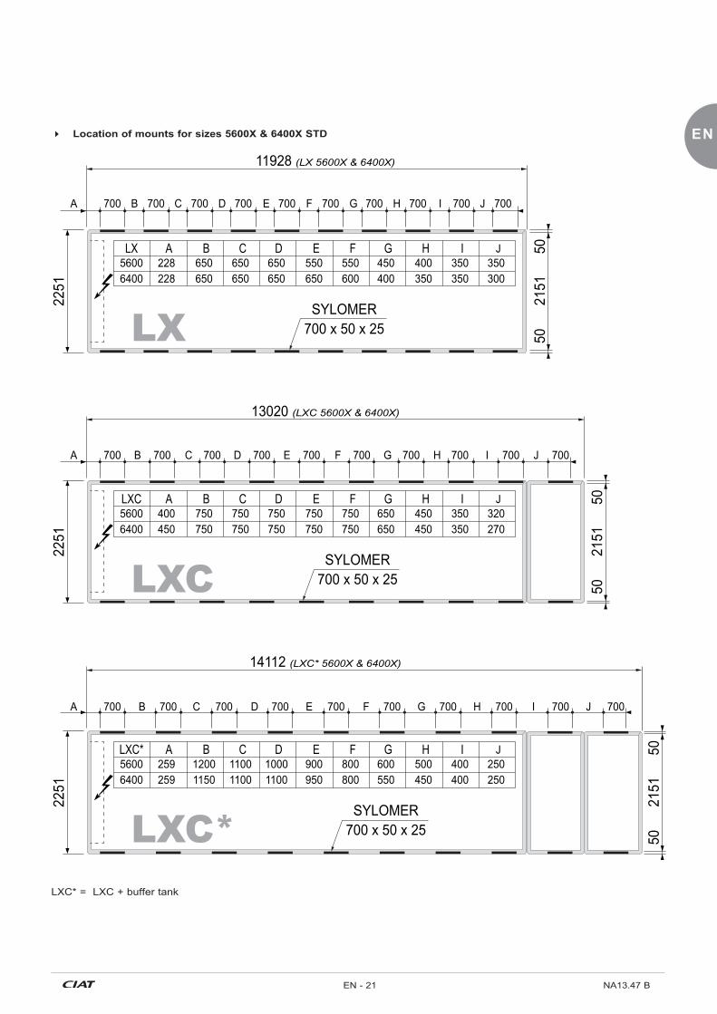
11928 (LX 5600X & 6400X)
2251
13020 (LXC 5600X & 6400X)
SYLOMER700 x 50 x 25
SYLOMER700 x 50 x 25
2151
5050
2151
5050
2251
14112 (LXC* 5600X & 6400X)
SYLOMER700 x 50 x 25
56006400
400450
750750
750750
750750
750750
750750
650650
450450
350350
320270
JLXC A B C D E F G H I
56006400
259259
12001150
11001100
10001100
900950
800800
600550
500450
400400
250250
JLXC* A B C D E F G H I
56006400
228228
650650
650650
650650
550650
550600
450400
400350
350350
350300
JLX A B C D E F G H I
700 B D FC E JIHG700 700 700 700 700 700 700 700 700A
700 B D FC E JIHG700 700 700 700 700 700 700 700 700A
700 B D FC E JIHG700 700 700 700 700 700 700 700 700A
LX
LXC
LXC*
� Location of mounts for sizes 5600X & 6400X STD
LXC* = LXC + buffer tank

NA13.47 B EN - 22
8.8 Anti-vibration mounts for HEE models (optional) � To limit the transmission of vibrations from the unit, install anti-vibration mounts underneath the unit in the locations provided
for this purpose. � CIAT accepts no responsibility for problems or damage to the unit, the structure or the building in the event of failure to use
the recommended mounts.
� Location of mounts for sizes 2500X HEE
LXC21
51
2251
5050
700258 700
6506 (LX 2500X)
700350700 700700 380 340420 410
2251
700201 700
7598 (LXC 2500X)
700650700 700700 650 400650 650
2151
5050
2151
5050
2251
700384 700
8690 (LXC* 2500X)
700650700 700700 650 150650 650 550 700
SYLOMER700 x 50 x 25
SYLOMER700 x 50 x 25
SYLOMER700 x 50 x 25LX
LXC*LXC* = LXC + buffer tank

EN
EN - 23 NA13.47 B
� Location of mounts for sizes 2800X & 3050X HEE
2151
2251
5050
7592 (LX 2800X & 3050X )
2251
8684 (LXC 2800X & 3050X)
SYLOMER700 x 50 x 25
SYLOMER700 x 50 x 25
2151
5050
2151
5050
2251
9776 (LXC* 2800X & 3050X)
SYLOMER700 x 50 x 25
LXC* A28003050
400100
B500500
C500500
D500500
E200500
F120120
G113113
H110110
I110110
J110110
LXC A28003050
650240
220 500 700 700750700700 700700 750450 450
A 700 F 700 700E700 700700 700B C
A 700 700 700 700 700 700700E700 700700 D F G H I JB C
LX
LXC
LXC*
B C650600
650600
D E650550
650450
F G600450 500
D G
LXC* = LXC + buffer tank

NA13.47 B EN - 24
� Location of mounts for sizes 3200X, 3400X, 3600X & 3900X HEE
2151
2251
5050
9756 (LX 3200X, 3400X, 3600X, 3900X)
2251
10848 (LXC 3200X, 3400X, 3600X, 3900X)
SYLOMER700 x 50 x 25
SYLOMER700 x 50 x 25
2151
5050
2151
5050
2251
11940 (LXC* 3200X, 3400X, 3600X, 3900X)
SYLOMER700 x 50 x 25
700
400
506 700 700 700 700700400
700 700700550 450 350 250650 700
164 700 700 700700 700400
700 700700 700400 300400 100 200650 550 550
700700 700 700700 700650
700 700700 700650 409650 125 50650 650 650
LX
LXC
LXC*LXC* = LXC + buffer tank

EN
EN - 25 NA13.47 B
� Location of mounts for sizes 4200X, 4500X & 4800X HEE
2151
2251
5050
11928 (LX 4200X, 4500X, 4800X)
2251
13020 (LXC 4200X, 4500X, 4800X)
SYLOMER700 x 50 x 25
SYLOMER700 x 50 x 25
2151
5050
2151
5050
2251
14112 (LXC* 4200X, 4500X, 4800X)
SYLOMER700 x 50 x 25
700 650 550 400550 400 450350350400700 700 700 700 700 700 700 700 700600
700 650 650 650650 650 120650650650700 700 700 700 700 700 700 700 700600
700 959 900 700950 900 350350510590700 700 700 700 700 700 700 700 700700
LX
LXC
LXC*LXC* = LXC + buffer tank

NA13.47 B EN - 26
9. CONNECTIONS9.1 Assembling the hydraulic module
9.2 Hydraulic connections � These must meet the following requirements:
- Respect the connection direction (inlet/outlet) indicated on the unit and the dimensional drawing.
- Install shut-off valves near the water inlets and outlets in order to isolate the exchangers.
- The water circuit must have as few bends and horizontal sections at different levels as possible.
- Thermally insulate the pipes and hoses to prevent heat loss and condensation.
- Install manual or automatic air bleed valves at the high points of the circuit(s). The bleed valves mounted on the machine are not designed to bleed the rest of the hydraulic circuit.
- We recommend installing flexible couplings between the water pipes and the exchangers to reduce the transmission of vibrations to the building as much as possible (essential when the unit is installed on anti-vibration mounts).
� The system pipework must be secured to the wall of the building and must not place any additional load on the unit.
� The installer must provide the necessary systems for filling and draining the energy transfer fluid.
� The piping must not transmit any force or vibrations to the evaporator.
� The pump(s) must be slaved to the unit (auxiliary operation switch of the pump to be wired). Stopping
the pumps will automatically cause the unit to stop to prevent any risk of freezing in the evaporator.
� Accessories essential to any hydraulic circuit (balancing valve, air bleed valves, low point connections for draining, expansion vessel, thermometer compartment, filter, etc.).
b1 b2
b2
b2
b2
b1
b1
b1
a1
a1
a1
a2
a2
a2a1
a1
a1
a2
a2
a2
Assembly on uprights:a1 = 6 M10 bolts + washersa2 = 6 M10 crimped sockets
Assembly on upper and lower cross members: b1 = 4 M10 bolts + washersb2 = 4 M10 crimped sockets on riveted spacers
9.3 LX - LXC series desuperheater exchangerPrinciple � Heat from gases released by the compressors can be recovered directly by a desuperheater heat exchanger on the unit to
produce free, additional hot water � This optional configuration requires assembly in our factories and is by order only � For heat recovery to be possible, the unit must be operating � For the same cooling or heating capacity, the desuperheater provides a source of free hot water and lowers the unit's electrical
power consumption.

EN
EN - 27 NA13.47 B
Diameter of hydraulic connections � The chilled water inlet and outlet connections are FLEXIBLE COLLARS.
POWERCIAT2LX LXC Desuperheater
(optional)Inlet Outlet Inlet Outlet2800 to 4800 STD/2500 to 3900 HEE DN 200 DN 200 DN 200 DN 200 DN50
5600 and 6400 STD/4200 to 4800 HEE DN 250 DN 250 DN 200 DN 200 DN50
HOSE CLAMP adapter kit (option) � "HOSE CLAMP + FLANGE" or "HOSE CLAMP + FLANGE + FLEXIBLE COUPLING" kits are supplied separately. � The kit and the system pipework must not transmit force to the unit's inlet and outlet pipes.
� "HOSE CLAMP + FLANGE" kit
� "HOSE CLAMP + FLANGE + FLEXIBLE COUPLING" kit A: to evaporator, pump or desuperheater B: to hydraulic system 1 - Hose clamp 2 - Flange adapter 3 - Flexible coupling
1
2
3
A
B
1
2
A
B 1 2
9.4 Specifications of the hydraulic connections
Hydraulic connections: configuration and precautionsTo ensure that the unit is commissioned and operates under the right conditions, the desuperheater water loop must be as short as possible. This will ensure that warm-up is gradual with a water flow rate of 10% of its nominal value, and that the nominal flow rate of the return waterat the desuperheater inlet is 50 °C.A hydraulic circuit which allows superheated water in the desuperheater to be produced very quickly (three-way valve + thermostat + sensor on desuperheater water inlet) is therefore recommendedThe thermostat setpoint must be at least +50°C.Note: special attention must be paid when selecting the
expansion vessel, as the temperature of the recovery water circuit can reach 115°C if the accelerator pump is off or if no hot water is consumed.
50°C
v3v
sm e
a
ds
50°C min.
Desuperheater option
domestic hot water
a: Shut-off valvee: Expansion vesselde: desuperheater
m: pressure gauges: safety valvev3v: three-way valve

NA13.47 B EN - 28
10.1 Control principle � The compressors are controlled by the Xtraconnect 2
control module based on the cold water return temperature. It activates or deactivates the compressors.
� In the standard configuration, the cold water control sensor is located on the evaporator water return.
� Condensation pressure control: - Activation or deactivation in series of the fans based on
the high pressure value monitored by the Xtraconnect 2 control console.
10.2 Xtraconnect 2 control module � All units in the POWERCIAT2 range are fitted with an
Xtraconnect 2 microprocessor-controlled electronic control and display module.
� Main functions: - Water temperature control. - There are four control options:
1. Water return difference.2. PID on the water outlet.3. Temperature difference according to the outdoor
temperature.4. Low temperature energy storage.
� In the standard configuration, the units use the chilled water return control: - Condensation pressure monitoring; - Compressor discharge temperature monitoring; - Safety device management; - Operating settings monitoring; - Management and equalisation of the compressor
operation times; - Unit weekly management; - Individualised diagnostic of each fault.
� For a detailed description of all these functions, refer to the Xtraconnect 2 practical manual.
10.3 Master/Slave control � Master/slave control enables two machines to be managed
in parallel. This requires the 2 machines to be connected using a bus link and one must be designated as the Master machine in control of the slave machine.
� However, these two machines must be configured separately as the Master machine does not impose its settings on the Slave machine. When a machine is configured as the Master, the settings for the Slave machine are fixed and cannot be accessed.
� The water law for the Master controls both machines.WARNING: the water laws should ideally be similar since, if there is a break in communication, each machine becomes independent (controlled by their own water law). � The "Master" machine sends the following information to
the "Slave" machine: - On/off; - Control temperature.
� The Master machine will not have access to detailed information about the Slave machine (fault details, operating readings, machine parameters, read only parameters, etc.) and vice versa.
� For more information, refer to the "Master/Slave management" section in the Xtraconnect 2 control manual.
10. CONTROL
9.5 Electrical connections � All wiring must be connected in accordance with the codes
and regulations that apply to the installation site (e.g. NFC 15100 in France).
� Always refer to the wiring diagram provided with the unit. � Observe the electrical supply specifications indicated on
the data plate. � The voltage must remain within the range indicated:
- Power circuit: 400 V (+/-10 %) - 3 ph - 50 Hz + Earth. - Control circuit: 230 V (+/-10 %) - 1 ph - 50 Hz + Earth.
� Phase unbalance must not exceed 2% and 10% for voltage and current, respectively.
� If any of the above conditions are not met, immediately contact your energy supplier and make sure the unit is not switched on until the necessary corrective actions have been taken. Failure to do so will automatically void the CIAT warranty.
� The cable sizes will be determined by the installer based on the installation site characteristics and regulations before any necessary adaptations are defined to facilitate connection on the site.
� Cable sizing criteria: - Maximum rated current (see § SPECIFICATIONS). - distance between the unit and its power source. - protection to be placed at the power source. - neutral mode.
- electrical connections (see wiring diagram supplied with the unit).
- temperature to which the wiring is exposed. - maximum cross section of the disconnect switch (see §
SPECIFICATIONS).
� Making the electrical connections:1. Connect the power circuit.2. Connect the protective conductor to the earth terminal.3. Connect the general fault display dry contact and
the automatic operation control dry contact (where applicable).
4. Interlock the compressors with the accelerator pump. � The automatic operation control must be connected using a
potential-free (dry) contact. � For the customer connection, refer to the unit's dimensional
drawing. � To prevent problems associated with accelerated corrosion,
earth the compressor via the screw on the casing.IMPORTANT: It is your responsibility to protect the unit from overvoltage coming from the mains or voltage spikes caused by lightning. Depending on the geographic location and the type of mains network (buried or overhead), you may need to install a lightning rod. Check your local electrical codes and regulations. Failure to comply with the requirements of standards in force in the country of installation (e.g. NF C 15100 in France) will void the CIAT warranty.

EN
EN - 29 NA13.47 B
10.4 Control and safety devices � All of the unit's safety devices are managed by the
electronic circuit board in the Xtraconnect 2 module. If a safety device trips and deactivates the unit, look for the fault, reset if necessary and clear the fault using the RESET button on the console.
� The unit will restart when the minimum time required by the short-cycle protection elapses.
� To find out the setting values of the various safety devices and the fault clearance procedures, refer to the manual for the Xtraconnect 2 control module.
� Low pressure (LP) sensorEach refrigeration circuit is equipped with an LP sensor. Located on the compressor intake, this sensor enables the user to view the LP value and allows the control module to provide a safety function by ensuring that the LP value does not fall below the fault threshold parameter. If it does fall below the setpoint value, the compressor for the refrigeration circuit concerned is powered off and an LED lights up on the console.Triggering: 0.3 bar (relative).
� High pressure (HP) sensorEach refrigeration circuit is equipped with an HP sensor. Located on the compressor discharge, it enables the user to view the HP value and allows the control module to provide a safety function by operating the fans.
� High pressure (HP) safety pressure switchThe HP safety pressure switch is the main safety device for the unit during operation. Each refrigeration circuit is equipped with two HP pressure switches connected in series. When the HP value exceeds the preset value of the pressure switch, power to the compressor in the refrigerating circuit concerned is cut off and the fault is indicated by an LED on the control console.The HP pressure switches are reset manually, thus any fault will be cleared by resetting the pressure switch and by pressing the RESET button on the console.Triggering: 20.5 bar (relative).
� Evaporator frost protection sensorThe evaporator is protected against freezing by two probes: - A sensor on the evaporator's chilled water outlet
monitors the temperature of the fluid to be cooled. If this temperature falls below the value set on the controller, the machine is powered off and the fault is indicated by an LED on the control console. This probe acts as a safety device and must therefore never be moved by the customer.
- A freon sensor monitors the temperature of the refrigerant at the evaporator inlet. If this temperature falls below the set value in the regulator, power to the compressor in the refrigerant circuit concerned is cut off and the fault is indicated by an LED on the regulator console.
The LP sensor and the exchanger water outlet sensor ensure permanent monitoring to prevent any damage to the exchanger. If the values of these two sensors become too divergent, the circuit concerned shuts down and the fault is indicated by a message and the illumination of a red LED on the console.
� Overpressure protectionEach refrigeration circuit in each unit is equipped with a device that protects it against the risk of overpressure resulting from fire: - Safety valves. These protect the HP and LP circuits
against overpressure caused by an increase in the external ���Q��������� ��� ���������Q����������?���??���������̀ ��! This valve is not considered to be a safety accessory ��� ��`��� �� ������� ^?@@� ��� ���� @� ��� � �� Q��������equipment directive.
- Maximum authorised pressure (PS) on the LP side: The LP value (indicated on the data plate) corresponds to the situation of the unit when powered off. This value is given according to the pressure/temperature ratio with an outdoor temperature of 65°C. This temperature corresponds to the least favourable situation to which the unit could be subjected, excluding ����������`��?
� Evaporator water circulation controllerThis component has a safety function. It is mounted on the chilled water outlet pipe and controls the circulation of the water in the evaporator.If this is not sufficient, the machine is shut down and an LED lights up on the console.
� Internal compressor protectionThe compressors are equipped as standard with the SE-E1 protection module. The module has 3 control functions.1. Temperature control for the motor (PTC sensor in the
winding), discharge gas and oil.2. Rotation direction control.3. Phase fault control.If there is a fault, the circuit concerned is shut down and an LED lights up on the console. The reset is performed manually (once the winding has cooled) by interrupting the L/N supply voltage for at least 5 seconds.
R1: Oil heatingR2: Oil temperature sensor (PTC)Wire colour: 1 = black, 2 = brown, 3 = blue
� Electronic expansion valveThe main controller is installed in the end cabinet.All the expansion valve operating parameters are preset, including evaporator superheating (7K). No adjustments can be made.The backup battery in this cabinet has a service life of 4 years. It allows the expansion valve to be closed in the event of a power failure.IMPORTANT: the valve must not be forced open when there is no refrigerant flow. When the system is powered off or evacuated, the start-up potential-free (dry) contact must remain open.
� Discharge sensorEach unit includes one discharge sensor per refrigerating circuit as standard. This sensor, which is located on the discharge piping, enables the user to view the discharge temperature value and allows the control module to provide a safety function.If the discharge temperature value exceeds the maximum temperature threshold set in the control module, the refrigeration circuit operates according to certain sequences or shuts down the circuit concerned, with an indication on the console.
� Setting the compressor capacityThe compressors are equipped with dual control. Continuous power control (pulsing of the magnetic valves to move the slide) is used to adjust the cooling power as required, and staged control is used to activate and deactivate the compressor.

NA13.47 B EN - 30
11.1 Preliminary checks � Check the following points:
1. Check that the network voltage matches the unit voltage and that its value remains within the authorised limits (+10% to -10% compared to rated voltage).
1. Check that the unit complies with the refrigeration and wiring diagrams.
2. Check that all components are as specified on the drawings.
3. Check that all documents and safety devices required by applicable European standards are present.
4. Check that there is sufficient clearance around the system for maintenance and emergency purposes.
5. Check that the clamps on all pipes are secure.6. Check that the welds and seals are in good condition.
Check there are no refrigerant leaks.7. Check that all mechanical guards are in place and
functional.8. Close the drain valve under the evaporator.9. After opening the water circuit valves, make sure that
water is flowing in the cooler while the pump is running.
11.2 Starting up the compressors � Before starting up, the hydraulic circuit must be drained.
For this operation, the pump(s) must have been started up. To enable operation without triggering the compressor(s), all our machines are delivered with the parameter "compressor on authorisation" set to "NO". The operation can therefore be carried out with no risk of starting up the compressors by setting the machine control to the "ON" position.
� Check that the discharge valves and liquid outlet valves are open.
� Power up the crankcase heaters for the compressors 6 hours before the compressors are to be started up.
� Once the hydraulic circuit has been drained, set the "compressor authorisation parameters" to "YES" to authorise start-up.
� Once the compressors have been started up, check:1. The operation of the water circulation controller.2. Touch the crankcases to make sure that the heaters are
operating correctly (they should be warm).
11.3 Starting up the unit � The system must have a heat load and water flowing in the
exchangers when it is started up and tested. - 1. Power up the main board
- 2. Check the configuration of the Xtraconnect 2 module.
- 3. Re-enter the setpoints.
- 4. Start the unit by pressing the On/Off button.
� The internal safety devices are activated. If one of these safety devices is triggered, trace the fault, reset the safety device if necessary and press the RESET button on the console to clear the fault.
� The unit will only start after 2 minutes (time required for inspection and acknowledgement of all safety devices). The control stages should operate in cascade mode, depending on the request.
� Use either of the following to switch off the unit in non-emergency situations: - The On/Off button on the console; - A dry contact on the automatic operation control.
� Do not use the master switch as the electrical cabinet must remain live (frost protection, crankcase heater).
11.4 Post-start-up checks
� Checking the compressors1. Ensure that each compressor is rotating in the correct
direction by checking that the discharge temperature rises quickly, the HP increases and the LP drops. If it is rotating in the wrong direction, the electric power supply is incorrectly wired (reversed phases). To restore rotation in the correct direction, swap the two power supply phases.
2. Check the direction of rotation of the fans.3. Check for any noise generated by the installation and
remedy if necessary.4. Check the compressor discharge temperature using a
contact sensor.5. Check that the absorbed current matches the values
indicated on the compressor's data plate.6. Check all safety devices to make sure they operate
correctly.7. During start-up and maintenance, the oil level must be
checked; it must be visible in the sight glass, both at full load and power reduction.
8. Only check the oil level in operation.
11. SYSTEM START-UP
The compressors are equipped with an automatic soft start system which reduces the starting torque and the acceleration times. This protects the mechanical parts and the motor, and substantially reduces the load on the system.
� Intake valve (option)The intake valve is used to isolate the compressor from the refrigerant when work is being carried out.IMPORTANT: - Make sure that the valves are fully open when the chiller
is started up. - Check the tightness of the valve locking lever and make
sure it is properly locked in order to ensure the valve is held in position.

EN
EN - 31 NA13.47 B
WARNING: Do not mix oil with other lubricants
� Checking the refrigerant charge � Each unit is shipped with an exact charge of refrigerant.
To make sure that the unit is filled with the correct charge of refrigerant, perform the following checks circuit by circuit with the system running at full capacity:1. Check that there are no bubbles in the liquid sight
glass. IMPORTANT: Do not rely on the sight glass on the electronic expansion valve.
2. Check the overheating value; it should be between 5 and 9°C.
3. Check the actual subcooling value at the condenser outlet. It must be between 5 and 10°C depending on the type of unit. NB: because the pressure drop in the micro-channel condensers is significant, the pressure measurement to calculate the subcooling must be taken at the condenser outlet. If the charge is too low, large bubbles will appear in the liquid sight glass, the suction pressure will drop and overheating on the compressor inlets will be high. Locate the leak, completely drain the refrigerant charge using a recovery machine, and fill the unit with a new charge. Repair the leak, pressure test the unit (do not exceed the maximum service pressure on the low pressure end) then refill the unit.
� The refrigerant must be liquid and charged via the liquid charging valve. The amounts of refrigerant indicated on the data plate must be added to each circuit in the unit.
� Repeat these steps if the subcooling temperature is below the specified values.
� NB: an excessively low suction pressure or an excessively high condensation pressure may sometimes be read when the unit is started up. There may be several reasons for this (see § "CORRECTIVE MAINTENANCE").
� Checking the hydraulics � As the exact total drop in system pressure is not known
at commissioning, adjust the flow of water with the control valve until the desired nominal rate is obtained. By causing the pressure in the hydraulic system to drop, this control valve aligns the System pressure/Flow curve with that of the pump so that the nominal flow rate corresponding to the desired operating point is obtained.
� The reading for the pressure drop in the exchanger will be used to monitor and adjust the installation's nominal flow rate.
� Follow the procedure described below:1. Open the control valve completely.2. Let the pump run for 2 hours to flush out any solid
particles in the circuit.3. Read the pressure drop in the exchanger when the
pump is switched on and then 2 hours afterwards.4. If the pressure drop has decreased, this means that
the screen filter is clogged. Remove and clean it.5. ��Q���������� ��`�����������Q�����_�����?6. If the system pressure drops far below the available
static pressure delivered by the pump, the resulting ������ ���� ����� ����� ��� ���� ��� � �� ���������� ��temperature between the exchanger inlet and outlet will be too high. This is why pressure drops must be minimised. Make sure that this difference is within the evaporator's application range (see technical manual).

NA13.47 B EN - 32
12.1 Recommendations for use � Noise
� While short-term exposure to a moderate noise level does not pose a risk, we recommend that persons working near to sources of significant noise wear hearing protection. However, this must not prevent the use of other essential protective equipment such as safety glasses and gas masks.
� Lubrication oil � The oils used in chillers pose very little risk to health
provided they are used correctly and under adequate industrial and personal hygiene conditions. However, always take the following precautions:1. As far as possible, avoid unnecessarily handling oily
components. Use protective creams.2. Oils are flammable and must be stored and handled
with care. Keep cleaning cloths away from sources of fire.
3. The oil contained in the compressor's lubrication system and the oil separator may cause burns, even after the system has been powered off.
4. If the system needs to be opened just after shutting down the compressor, e.g. to clean the oil strainer, be sure to let the oil cool down for long enough so that any oil splashes no longer pose a hazard (<35 °C).
5. Containers must be stored with their caps on. Avoid using oil from an opened container stored under incorrect conditions.
� Refrigerants - general � Refrigeration systems contain pressurised fluids and
gases. Take all the necessary precautions before opening a circuit.
� Always wear safety glasses, gloves and other protective equipment when opening pipes or tanks that may contain fluids.
� Partially opening the primary refrigeration circuit will release refrigerant into the atmosphere. It is essential to minimise the amount of lost refrigerant by pumping the charge and isolating it in another part of the system.
� The lubricating oil, and the low-temperature liquid refrigerant in particular, may cause inflammation similar to burns if they come into contact with skin or eyes. Store unused refrigerant in the appropriate containers and limit the amounts stored in mechanical rooms.
� Cylinders and tanks of refrigerant must be handled with care and signs warning users of the related poisoning, fire and explosion hazards must be clearly visible.
� Refrigerant that reaches the end of its life must be collected and recycled in accordance with applicable regulations.
� Hydrofluorocarbon refrigerants � Although non-toxic, vapours from hydrofluorocarbon
refrigerants are still hazardous because they are heavier than air and can force the latter out of the machine rooms.
� If refrigerant is accidentally released, ventilate the room with fans. Exposure levels in workplaces must be kept to a practical minimum and must never exceed the recognised limit of 1000 particles per million (ppm) for an 8-hour working day and a 40-hour working week.
� Although hydrofluorocarbon refrigerants are not flammable, keep them away from open flames (e.g. cigarettes) as temperatures of over 300°C cause their vapours to break down and form phosgene, hydrogen fluoride, hydrogen chloride and other toxic compounds. These compounds may produce severe physiological consequences if accidentally inhaled or swallowed.
12. USE
� Long stoppages can cause corrosion to develop or lead to its acceleration by differential aeration or bacterial development, mainly due to the presence of water. As soon as an installation is stopped for a few weeks (downtime, closing down for holidays, etc.) the water circuit must be carefully drained. If necessary, use compressed air to
remove any stagnant water, especially from inside pipes. � If the circuit is left without water for over a month, fill it with
nitrogen to prevent corrosion.
12.2 Prolonged stoppages

EN
EN - 33 NA13.47 B
13. MAINTENANCE13.1 Recommendations for maintenance � To ensure the unit operates correctly, we recommend that you
sign a maintenance contract with your installer or an approved maintenance company.
� All work on the unit's electrical or refrigerant systems must be performed by a qualified authorised technician.
� Perform operating inspections in accordance with national regulations.
� Do not work on any electrical components without first switching off the unit's main disconnect switch in the electrics box. Although the compressors are switched off, the power circuit remains live until the unit's disconnect switch is opened. Other components may remain energised by external controllers connected to the orange disconnect terminals on the main terminal strip. Disconnect the removable portion of these terminals before commencing any work.
� The surfaces of the compressor and pipes may reach temperatures of over 100°C and cause burns if touched. Likewise, the surfaces of the compressor may in some cases drop to freezing temperatures which can cause frostbite.
� Keep the unit clean. Retouch the paintwork if necessary. � To prevent accidents and ensure proper ventilation of the
condenser, keep the unit and the space around it clean and clear of clutter.
� Check the fouling level of the coil. If necessary, remove any dust, fibres or leaves using a soft brush or vacuum cleaner. It can be cleaned using a water spray: - at low pressure; - in the direction of the fins; - in the opposite direction to the air.
� Never climb on the machine or its copper refrigerant pipes. Use a platform when working at height.
� Any opening or closing of a shut-off valve must be performed with the unit off.
� The liquid valve (located just before the dryer) must be opened completely when there is refrigerant in the circuit.
The small size of the micro-channel condensers means that not all of the fluid can be stored in the HP section.
13.2 Preventive maintenance � Keep informed about current environmental standards
and applicable regulations concerning the site, particularly regarding regular inspections.
� The intervals for cleaning are given as a guide and should be adapted to each unit.
Weekly checks � With the unit running at full capacity, check the following
values: - look for traces of water or oil under or around the unit,
and listen for any unusual noises; - LP compressor suction pressure; - HP compressor discharge pressure; - the water inlet and outlet temperatures in the exchangers; - the charge via the liquid sight glass and the condition
of the charge using the coloured indicator on the sight glass;
- the oil level and its appearance. If the colour changes, check the quality;
- check whether the safety devices operate correctly.
Monthly checks � In addition to the weekly checks, you should also check:
- the operation of the compressor's capacity control system;
- for corrosion on all metal parts (base frame, casing, exchangers, electrics boxes, etc.).
- the condition of the insulating foam (detachment or tears);
- the energy transfer fluids for any impurities which could cause wear or corrosion in the exchanger;
- the sealing of the various circuits; - whether the safety devices and expansion valves
operate correctly.
Annual checks � In addition to the monthly checks, you should also check:
- that the intake valve locking lever operates correctly, as its position can change due to vibrations in the pipes. Actuate the intake valve (option) at least once a year.
- the sealing of the retaining valve on the compressor discharge/separator. Clean or replace this valve if necessary.
- the filter dryer for clogging (measure the difference in the temperature of the copper pipes at the filter dryer inlet and outlet).
- the electrical connections to ensure they are tight and in good condition.
- the insulation of the motor and the resistance of the coils. Disconnect all the cables.
- the condition of the contacts and the current at full load on all 3 phases.
- for the presence of moisture in the electrics box. - the operation of the water circulation controller. - the water quality or condition of the heat transfer fluid. - the concentration of the antifreeze solution (MEG or
PEG) - Clean the water filter and bleed air from the circuit. - Clean the exchangers and check the pressure drop in
the evaporator. � Take an oil sample from the separator every 5000 hours for
analysis. if acid, water or metal particles are found, replace the oil in the circuit concerned and the filter dryer. The oil should in principle be changed every three years.
� If the whole oil charge is being changed, use only new oil of the same grade as the original oil, which has been stored in a hermetically sealed container until charging. The same oil type must be used.
� Check the voltage of the expansion valve coils.Replace these if necessary (max. lifespan: 4 years).

NA13.47 B EN - 34
13.3 Corrective maintenance � Experience shows that common faults are often easy to fix. There are three such causes in particular:
1. Exchanger fouling.2. Problems with the hot or cold fluid circuits.3. Failures of electric components such as relay coils or electrical valves, etc.
� Maintenance of micro-channel condensers (§13): � You are recommended to only use water to clean the outer surface of the condenser. If another fluid is used, the following
recommendations must be observed: - The pH must be between 5 and 9. - The solution must not contain chlorides, sulphates, copper, iron, nickel or titanium. - The solution must have been tested to demonstrate it is compatible with aluminium.
� You may use a high-pressure cleaner provided that the following recommendations are observed: - Before cleaning the condensers, remove all soap or cleaning fluid from the unit. - Clean the condensers by spraying the jets perpendicular to the face area, in an even and regular motion from top to
bottom. - Do not exceed 900 Psig or a spray angle of 45°. - The nozzle must be at least 30 cm (12 ") from the condenser. - Remove any excess water from the condenser.
� Faults detected by the safety devices are not necessarily caused by a sudden change in the magnitude being monitored. Taken regularly, readings should make it possible to anticipate future trips.
� Perform the checks listed in the table below if you notice that a magnitude deviates from its normal value and gradually moves closer to the safety limit.
Faults Probable cause Solution
Suction pressure too low
- Presence of air in the cooled fluid circuit - Bleed the cooled circuit
- Insufficient cooled fluid flow rate - Check that the valves on the cooled fluid circuit open - Check the rotation direction of the pump and that there is no cavitation
- Sufficient cooled fluid flow rate but the unit is too powerful for the circuit load
- Recalculate the heat load - Check the operation of the capacity control system
- Compressor suction valve opening insufficient (option)
- Open the compressor suction valve fully
- Lack of refrigerant - Find the leak(s) and top up the charge
Excessive discharge pressure
- Poor ventilation (suction or discharge blocked), fans turning in wrong direction. - Suction air too hot (recirculation)
- Check the operation of the air condenser
- Insufficient opening of the compressor discharge valve
- Open the compressor discharge valve fully
Discharge temperature
too high - Problem on fluid injection system - Check the operation of the injection expansion valve
Oil level too low
- Oil not topped up after servicing - Top up with oil
Motor fault
- Circuit breakers faulty
- Insufficient power supply voltage
- Insufficient motor cooling
- Replace them
- Check the electrical installation and contact your energy supplier if necessary
- Make sure that nothing is preventing the motor from being cooled

EN
EN - 35 NA13.47 B
Faults Probable cause Solution
Cooling fluid outlet temperature
too high
a) The suction pressure is above the normal level:
- Controller setpoint incorrect
- Heat load higher than specified
- Water flow rate too high
- Electronic control inoperative
- Power variation system faulty
- Display the correct setpoint
- Check the reports (or install an additional unit if available)
- Adjust the flow rate to the specified value
- Check the operation of the temperature and power controllers
- Check the operation of the compressor control slide
b) The suction pressure is below the normal level:
- Lack of refrigerant
- Incorrect refrigerant supply to evaporator
- Find the leak(s) and top up the charge
- Check the electrical valve, the expansion valve and, if necessary, the filter dryer fouling level
14. PERMANENT SHUTDOWN
14.1 Decommissioning � Separate the units from their energy sources, allow them to
cool then drain them completely.
14.2 Dismantling recommendations � Use the original lifting equipment. � Sort the components according to their material for recycling
or disposal, in accordance with regulations in force. � Check whether any part of the unit can be recycled for
another purpose.
14.3 Fluids to be recovered for treatment - R134a refrigerant - Energy transfer fluid: depending on the installation,
water, glycol/water mix... - Compressor oil
14.4 Materials to be recovered for recycling - Steel - Copper - Aluminium - Plastics - Polyurethane foam (insulation)
14.5 Waste Electrical and Electronic Equipment (WEEE) � At the end of its life, this equipment must be disassembled
and contaminated fluids removed by professionals and processed via approved channels for electrical and electronic equipment (WEEE). - In France, CIAT has formed a partnership with ECOLOGIC
for the collection and recovery of professional waste governed by European Directive WEEE 2012/19/EU. This partnership simplifies the mandatory administrative procedures and ensures that old equipment is recovered via an official, structured channel. In terms of renovation work in France (mainland and overseas), for every CIAT unit installed, our partner will collect and dismantle your existing equipment (see conditions with Ecologic). To request collection, please contact Ecologic: 01 30 57 79 14 - [email protected]
- For other countries, please refer to the legislation in force and the specific solutions available to ensure your waste is processed legally.

NA13.47 B EN - 36
15. OPERATING READINGS
� Record the operating readings at least twice a year and at each start-up for units used seasonally.
Date/Time
Com
pres
sor
Intake pressure bar
Intake temperature °C
Condensation pressure bar
Discharge temperature °C
Air-
cool
ed
con
dens
er
Gas inlet temperature °C
Liquid outlet temperature °C
Air inlet temperature °C
Air outlet temperature °C
Evap
orat
or
Water inlet temperature °C
Water outlet temperature °C
Liquid inlet temperature °C
Evaporator outlet temperature °C
Date/Time
Nominal voltage V
Voltage at terminals V
Compressor input current A
Fan motor input current A
Pump motor input current (LXH) A
Oil pressure bar
Normal oil level
Antifreeze protection triggering temperature °C
Mechanical inspection: tubing, fastenings, etc.
Electrical connection tightness check
External coil cleaning
Control check

EN
EN - 37 NA13.47 B

NA13.47 B EN - 38


Registered addressAvenue Jean Falconnier B.P. 14
01350 Culoz - France Tel. : +33 (0)4 79 42 42 42Fax: +33 (0)4 79 42 42 [email protected] - www.ciat.com
Compagnie Industrielled’Applications Thermiques
Corporation with a capital of €26,728,480R.C.S. Bourg-en-Bresse B 545.620.114
Registered addressAvenue Jean Falconnier B.P. 14
01350 Culoz - France Tel. : +33 (0)4 79 42 42 42Fax: +33 (0)4 79 42 42 [email protected] - www.ciat.com
Compagnie Industrielled’Applications Thermiques
Corporation with a capital of €26,728,480R.C.S. Bourg-en-Bresse B 545.620.114
Document non contractuel. Dans le souci constant,d’améliorer son matériel, CIAT se réserve le droit de procéder
sans préavis à toutes modifications techniques.
Non contractual document. With the thought of materialimprovement always in mind, CIAT reserves the right,
without notice, to proceed with any technical modification.
Dieses Dokument ist keine Vertragsunterlage. Da wir ständig bemüht sind, unser Material noch weiter zu verbessern, behält sich CIAT das Recht vor, technische Änderungen ohne vorherige Ankündigung vorzunehmen.
Documento no contractual. En la preocupaciòn constante demejorar su material, CIAT se reserva el derecho de proceder,
sin previo aviso, a cualquier modificaciòn technica.
Documento non contrattuale. Nella preoccupazione costante dimigliorare il suo materiale, CIAT si riserva il diritto di procederesenza preavviso a tutte le modificazioni tecniche necessarie.
CIAT ServiceTel.: 08 11 65 98 98 - Fax: 08 26 10 13 63
(0.15 € / min)


![2019 ISDE apparatenlijst warmtepompen 20-3-2019...Meldcode Merk Type Vermogen [kW] Indicatief subsidiebedrag Lucht/water-warmtepompen ≤ 70 kW thermisch aansluitvermogen KA11189 Aermec](https://static.fdocuments.net/doc/165x107/5e9fc6419825de74b71ed2f8/2019-isde-apparatenlijst-warmtepompen-20-3-2019-meldcode-merk-type-vermogen.jpg)


