
03-VLAN and MAC Address Configuration
46
VLAN and MAC Address Configuration Content 1 Content CHAPTER 1 VLAN CONFIGURATION...................................... 1-1 1.1 VLAN CONFIGURATION ......................................................................... 1-1 1.1.1 Introduction to VLAN ..............................................................................1-1 1.1.2 VLAN Configuration Task List ...............................................................1-2 1.1.3 Typical VLAN Application.......................................................................1-5 1.1.4 Typical Application of Hybrid Port ........................................................1-6 1.2 GVRP CONFIGURATION ......................................................................... 1-8 1.2.1 Introduction to GVRP..............................................................................1-8 1.2.2 GVRP Configuration Task List ...............................................................1-9 1.2.3 Example of GVRP ..................................................................................1-10 1.2.4 GVRP Troubleshooting.........................................................................1-12 1.3 DOT1Q-TUNNEL CONFIGURATION ......................................................... 1-13 1.3.1 Introduction to Dot1q-tunnel ...............................................................1-13 1.3.2 Dot1q-tunnel Configuration .................................................................1-14 1.3.3 Typical Applications of the Dot1q-tunnel ...........................................1-14 1.3.4 Dot1q-tunnel Troubleshooting.............................................................1-16 1.4 VLAN- TRANSLATION CONFIGURATION ................................................. 1-16 1.4.1 Introduction to VLAN-translation ........................................................1-16 1.4.2 VLAN-translation Configuration ..........................................................1-16 1.4.3 Typical application of VLAN-translation .............................................1-17 1.4.4 VLAN-translation Troubleshooting .....................................................1-18 1.5 DYNAMIC VLAN CONFIGURATION ........................................................ 1-18 1.5.1 Introduction to Dynamic VLAN............................................................1-18 1.5.2 Dynamic VLAN Configuration..............................................................1-19 1.5.3 Typical Application of the Dynamic VLAN .........................................1-21 1.5.4 Dynamic VLAN Troubleshooting .........................................................1-22 1.6 VOICE VLAN CONFIGURATION ............................................................. 1-23 1.6.1 Introduction to Voice VLAN .................................................................1-23 1.6.2 Voice VLAN Configuration ...................................................................1-23 1.6.3 Typical Applications of the Voice VLAN .............................................1-24
-
Upload
salmanfarhad -
Category
Documents
-
view
79 -
download
2
description
VLAN
Transcript of 03-VLAN and MAC Address Configuration
VLAN and MAC Address Configuration Content
1
Content
CHAPTER 1 VLAN CONFIGURATION ...................................... 1-1
1.1 VLAN CONFIGURATION ......................................................................... 1-1
1.1.1 Introduction to VLAN ..............................................................................1-11.1.2 VLAN Configuration Task List ...............................................................1-21.1.3 Typical VLAN Application .......................................................................1-51.1.4 Typical Application of Hybrid Port ........................................................1-6
1.2 GVRP CONFIGURATION ......................................................................... 1-8
1.2.1 Introduction to GVRP ..............................................................................1-81.2.2 GVRP Configuration Task List ...............................................................1-91.2.3 Example of GVRP ..................................................................................1-101.2.4 GVRP Troubleshooting .........................................................................1-12
1.3 DOT1Q-TUNNEL CONFIGURATION ......................................................... 1-13
1.3.1 Introduction to Dot1q-tunnel ...............................................................1-131.3.2 Dot1q-tunnel Configuration .................................................................1-141.3.3 Typical Applications of the Dot1q-tunnel ...........................................1-141.3.4 Dot1q-tunnel Troubleshooting .............................................................1-16
1.4 VLAN-TRANSLATION CONFIGURATION ................................................. 1-16
1.4.1 Introduction to VLAN-translation ........................................................1-161.4.2 VLAN-translation Configuration ..........................................................1-161.4.3 Typical application of VLAN-translation .............................................1-171.4.4 VLAN-translation Troubleshooting .....................................................1-18
1.5 DYNAMIC VLAN CONFIGURATION ........................................................ 1-18
1.5.1 Introduction to Dynamic VLAN ............................................................1-181.5.2 Dynamic VLAN Configuration ..............................................................1-191.5.3 Typical Application of the Dynamic VLAN .........................................1-211.5.4 Dynamic VLAN Troubleshooting .........................................................1-22
1.6 VOICE VLAN CONFIGURATION ............................................................. 1-23
1.6.1 Introduction to Voice VLAN .................................................................1-231.6.2 Voice VLAN Configuration ...................................................................1-231.6.3 Typical Applications of the Voice VLAN .............................................1-24
VLAN and MAC Address Configuration Content
2
1.6.4 Voice VLAN Troubleshooting ...............................................................1-25
1.7 MULTI-TO-ONE VLAN TRANSLATION CONFIGURATION .......................... 1-26
1.7.1 Introduction to Multi-to-One VLAN Translation .................................1-261.7.2 Multi-to-One VLAN Translation Configuration ...................................1-261.7.3 Typical application of Multi-to-One VLAN Translation ......................1-271.7.4 Multi-to-One VLAN Translation Troubleshooting ..............................1-28
1.8 SUPER VLAN CONFIGURATION ............................................................ 1-28
1.8.1 Introduction to Super VLAN .................................................................1-281.8.2 Super VLAN Configuration ..................................................................1-301.8.3 Typical Application of Super VLAN .....................................................1-311.8.4 Super VLAN Troubleshooting ..............................................................1-33
CHAPTER 2 MAC TABLE CONFIGURATION ........................... 2-1
2.1 INTRODUCTION TO MAC TABLE .............................................................. 2-1
2.1.1 Obtaining MAC Table ..............................................................................2-12.1.2 Forward or Filter ......................................................................................2-3
2.2 MAC ADDRESS TABLE CONFIGURATION TASK LIST ................................. 2-4
2.3 TYPICAL CONFIGURATION EXAMPLES ..................................................... 2-5
2.4 MAC TABLE TROUBLESHOOTING ........................................................... 2-6
2.5 MAC ADDRESS FUNCTION EXTENSION ................................................... 2-6
2.5.1 MAC Address Binding ............................................................................2-6
2.6 MAC NOTIFICATION CONFIGURATION ..................................................... 2-8
2.6.1 Introduction to MAC Notification ..........................................................2-82.6.2 MAC Notification Configuration ............................................................2-92.6.3 MAC Notification Example ...................................................................2-102.6.4 MAC Notification Troubleshooting ...................................................... 2-11
VLAN and MAC Address Configuration Chapter 1 VLAN Configuration
1-1
Chapter 1 VLAN Configuration
1.1 VLAN Configuration
1.1.1 Introduction to VLAN
VLAN (Virtual Local Area Network) is a technology that divides the logical addresses
of devices within the network to separate network segments basing on functions,
applications or management requirements. By this way, virtual workgroups can be formed
regardless of the physical location of the devices. IEEE announced IEEE 802.1Q protocol
to direct the standardized VLAN implementation, and the VLAN function of switch is
implemented following IEEE 802.1Q.
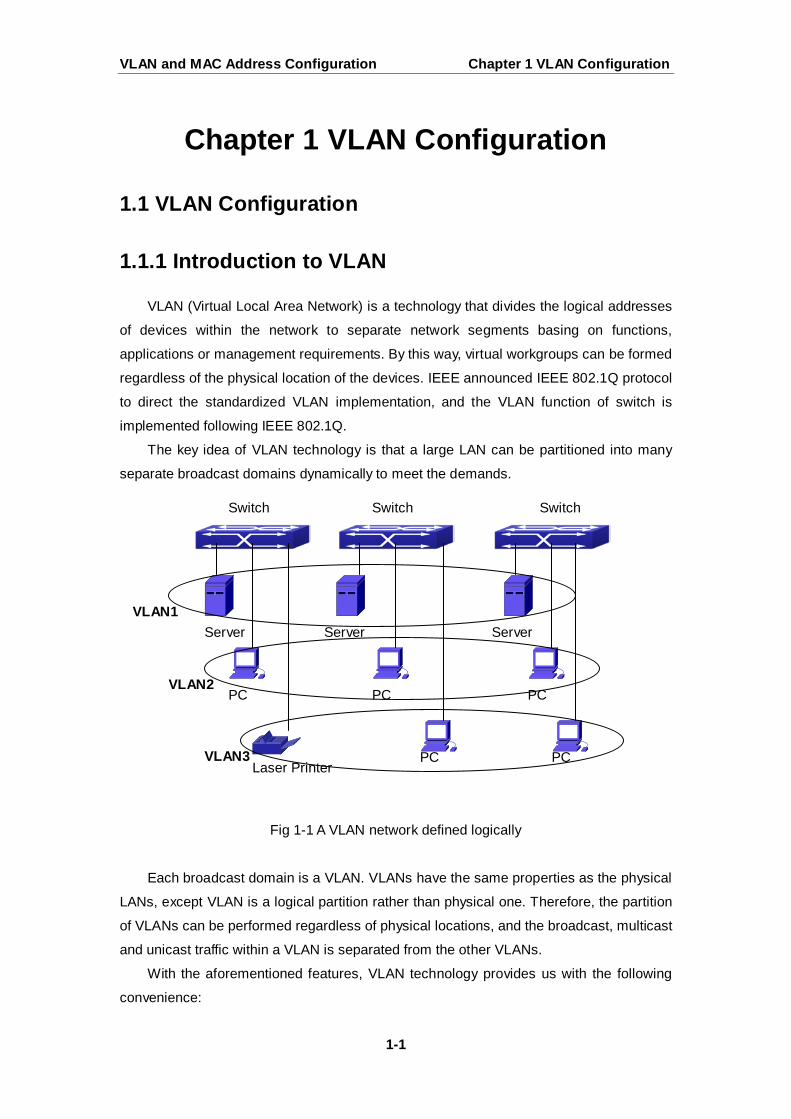
The key idea of VLAN technology is that a large LAN can be partitioned into many
separate broadcast domains dynamically to meet the demands.
Fig 1-1 A VLAN network defined logically
Each broadcast domain is a VLAN. VLANs have the same properties as the physical
LANs, except VLAN is a logical partition rather than physical one. Therefore, the partition
of VLANs can be performed regardless of physical locations, and the broadcast, multicast
and unicast traffic within a VLAN is separated from the other VLANs.
With the aforementioned features, VLAN technology provides us with the following
convenience:
Switch Switch Switch
Server Server Server
PC PC PC
PC PC Laser Printer
VLAN1
VLAN2
VLAN3
VLAN and MAC Address Configuration Chapter 1 VLAN Configuration
1-2
Improving network performance
Saving network resources
Simplifying network management
Lowering network cost
Enhancing network security
Switch Ethernet Ports can works in three kinds of modes: Access, Hybrid and Trunk,
each mode has a different processing method in forwarding the packets with tagged or
untagged.
The ports of Access type only belongs to one VLAN, usually they are used to connect
the ports of the computer.
The ports of Trunk type allow multi-VLANs to pass, can receive and send the packets
of multi-VLANs. Usually they are used to connect between the switches.
The ports of Hybrid type allow multi-VLANs to pass, can receive and send the
packets of multi-VLANs. They can be used to connect between the switches, or to a
computer of the user.
Hybrid ports and Trunk ports receive the data with the same process method, but
send the data with different method: Hybrid ports can send the packets of multi-VLANs
without the VLAN tag, while Trunk ports send the packets of multi-VLANs with the VLAN
tag except the port native VLAN.
The switch implements VLAN and GVRP (GARP VLAN Registration Protocol) which
are defined by 802.1Q. The chapter will explain the use and the configuration of VLAN
and GVRP in detail.
1.1.2 VLAN Configuration Task List
1. Create or delete VLAN
2. Set or delete VLAN name
3. Assign Switch ports for VLAN
4. Set the switch port type
5. Set Trunk port
6. Set Access port
7. Set Hybrid port
8. Enable/Disable VLAN ingress rules on ports
9. Configure Private VLAN
10. Set Private VLAN association
11. Specify internal VLAN ID
1. Create or delete VLAN
Command Explanation
VLAN and MAC Address Configuration Chapter 1 VLAN Configuration
1-3
2. Set or delete VLAN name
3. Assigning Switch ports for VLAN
4. Set the Switch Port Type
5. Set Trunk port
6. Set Access port
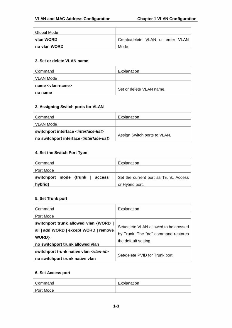
Global Mode
vlan WORD no vlan WORD
Create/delete VLAN or enter VLAN
Mode
Command Explanation
VLAN Mode
name <vlan-name> no name
Set or delete VLAN name.
Command Explanation
VLAN Mode
switchport interface <interface-list>
no switchport interface <interface-list> Assign Switch ports to VLAN.
Command Explanation
Port Mode
switchport mode {trunk | access |
hybrid}
Set the current port as Trunk, Access
or Hybrid port.
Command Explanation
Port Mode
switchport trunk allowed vlan {WORD | all | add WORD | except WORD | remove WORD} no switchport trunk allowed vlan
Set/delete VLAN allowed to be crossed
by Trunk. The “no” command restores
the default setting.
switchport trunk native vlan <vlan-id>
no switchport trunk native vlan Set/delete PVID for Trunk port.
Command Explanation
Port Mode
VLAN and MAC Address Configuration Chapter 1 VLAN Configuration
1-4
7. Set Hybrid port
8. Disable/Enable VLAN Ingress Rules
9. Configure Private VLAN
10. Set Private VLAN association
11. Specify internal VLAN ID
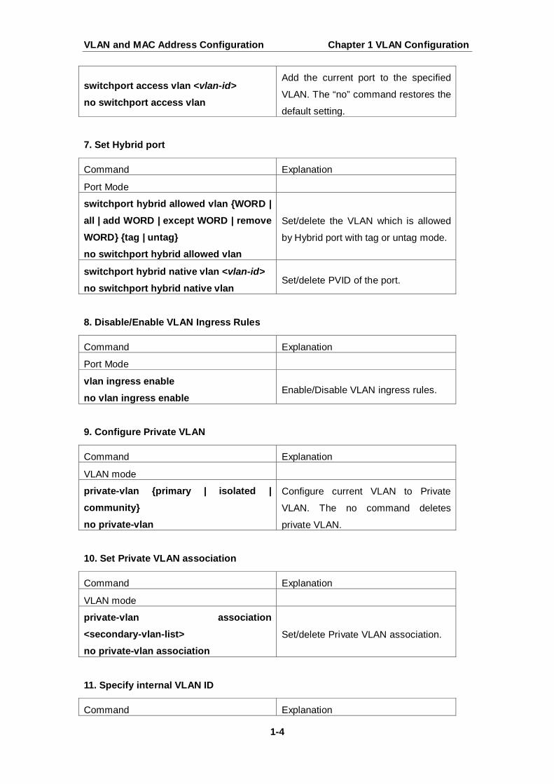
switchport access vlan <vlan-id>
no switchport access vlan
Add the current port to the specified
VLAN. The “no” command restores the
default setting.
Command Explanation
Port Mode
switchport hybrid allowed vlan {WORD | all | add WORD | except WORD | remove WORD} {tag | untag} no switchport hybrid allowed vlan
Set/delete the VLAN which is allowed
by Hybrid port with tag or untag mode.
switchport hybrid native vlan <vlan-id>
no switchport hybrid native vlan Set/delete PVID of the port.
Command Explanation
Port Mode
vlan ingress enable no vlan ingress enable
Enable/Disable VLAN ingress rules.
Command Explanation
VLAN mode
private-vlan {primary | isolated | community} no private-vlan
Configure current VLAN to Private
VLAN. The no command deletes
private VLAN.
Command Explanation
VLAN mode
private-vlan association <secondary-vlan-list> no private-vlan association
Set/delete Private VLAN association.
Command Explanation
VLAN and MAC Address Configuration Chapter 1 VLAN Configuration
1-5
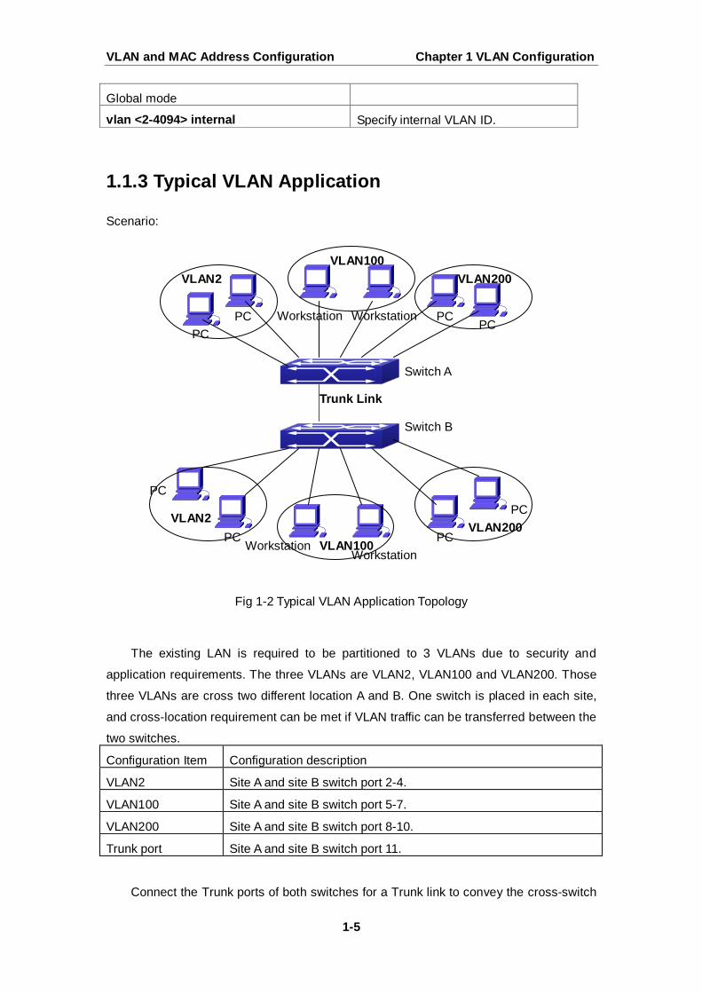
1.1.3 Typical VLAN Application
Scenario:
Fig 1-2 Typical VLAN Application Topology
The existing LAN is required to be partitioned to 3 VLANs due to security and
application requirements. The three VLANs are VLAN2, VLAN100 and VLAN200. Those
three VLANs are cross two different location A and B. One switch is placed in each site,
and cross-location requirement can be met if VLAN traffic can be transferred between the
two switches.
Configuration Item Configuration description
VLAN2 Site A and site B switch port 2-4.
VLAN100 Site A and site B switch port 5-7.
VLAN200 Site A and site B switch port 8-10.
Trunk port Site A and site B switch port 11.
Connect the Trunk ports of both switches for a Trunk link to convey the cross-switch
Global mode
vlan <2-4094> internal Specify internal VLAN ID.
VLAN2 VLAN100
VLAN200
VLAN2
VLAN100 VLAN200
Trunk Link
Switch A
Switch B
PC PC PC
PC
PC
PC
PC
PC
Workstation Workstation
Workstation Workstation
VLAN and MAC Address Configuration Chapter 1 VLAN Configuration
1-6
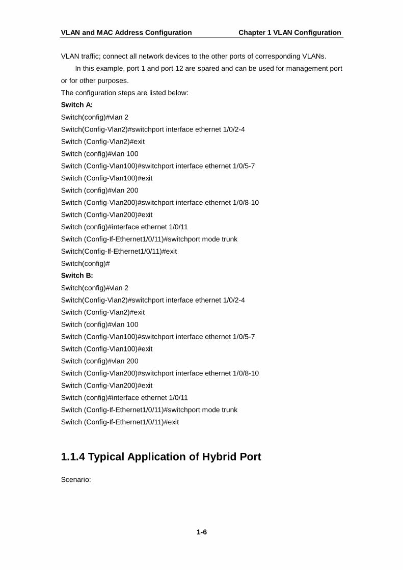
VLAN traffic; connect all network devices to the other ports of corresponding VLANs.
In this example, port 1 and port 12 are spared and can be used for management port
or for other purposes.
The configuration steps are listed below:
Switch A:
Switch(config)#vlan 2
Switch(Config-Vlan2)#switchport interface ethernet 1/0/2-4
Switch (Config-Vlan2)#exit
Switch (config)#vlan 100
Switch (Config-Vlan100)#switchport interface ethernet 1/0/5-7
Switch (Config-Vlan100)#exit
Switch (config)#vlan 200
Switch (Config-Vlan200)#switchport interface ethernet 1/0/8-10
Switch (Config-Vlan200)#exit
Switch (config)#interface ethernet 1/0/11
Switch (Config-If-Ethernet1/0/11)#switchport mode trunk
Switch(Config-If-Ethernet1/0/11)#exit
Switch(config)#
Switch B:
Switch(config)#vlan 2
Switch(Config-Vlan2)#switchport interface ethernet 1/0/2-4
Switch (Config-Vlan2)#exit
Switch (config)#vlan 100
Switch (Config-Vlan100)#switchport interface ethernet 1/0/5-7
Switch (Config-Vlan100)#exit
Switch (config)#vlan 200
Switch (Config-Vlan200)#switchport interface ethernet 1/0/8-10
Switch (Config-Vlan200)#exit
Switch (config)#interface ethernet 1/0/11
Switch (Config-If-Ethernet1/0/11)#switchport mode trunk
Switch (Config-If-Ethernet1/0/11)#exit
1.1.4 Typical Application of Hybrid Port
Scenario:
VLAN and MAC Address Configuration Chapter 1 VLAN Configuration
1-7
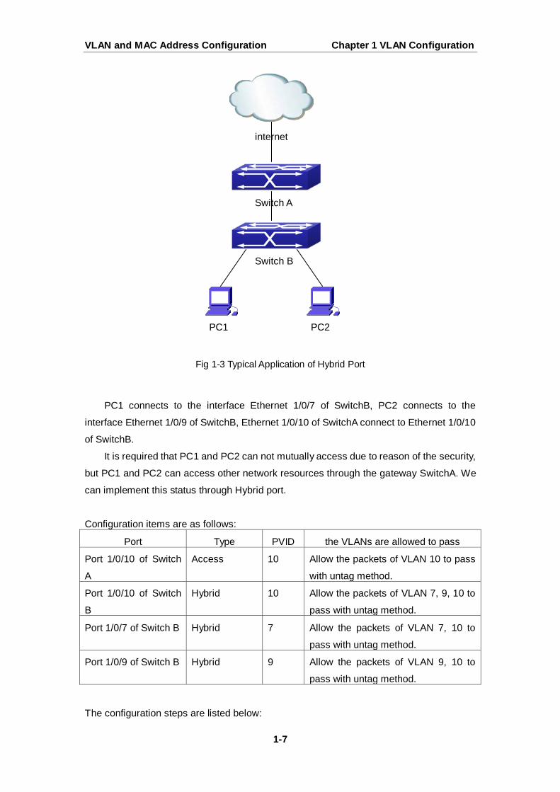
Fig 1-3 Typical Application of Hybrid Port
PC1 connects to the interface Ethernet 1/0/7 of SwitchB, PC2 connects to the
interface Ethernet 1/0/9 of SwitchB, Ethernet 1/0/10 of SwitchA connect to Ethernet 1/0/10
of SwitchB.
It is required that PC1 and PC2 can not mutually access due to reason of the security,
but PC1 and PC2 can access other network resources through the gateway SwitchA. We
can implement this status through Hybrid port.
Configuration items are as follows:
Port Type PVID the VLANs are allowed to pass
Port 1/0/10 of Switch
A
Access 10 Allow the packets of VLAN 10 to pass
with untag method.
Port 1/0/10 of Switch
B
Hybrid 10 Allow the packets of VLAN 7, 9, 10 to
pass with untag method.
Port 1/0/7 of Switch B Hybrid 7 Allow the packets of VLAN 7, 10 to
pass with untag method.
Port 1/0/9 of Switch B Hybrid 9 Allow the packets of VLAN 9, 10 to
pass with untag method.
The configuration steps are listed below:
Switch A
Switch B
PC1 PC2
internet
VLAN and MAC Address Configuration Chapter 1 VLAN Configuration
1-8
Switch A:
Switch(config)#vlan 10
Switch(Config-Vlan10)#switchport interface ethernet 1/0/10 Switch B:
Switch(config)#vlan 7;9;10
Switch(config)#interface ethernet 1/0/7
Switch(Config-If-Ethernet1/0/7)#switchport mode hybrid
Switch(Config-If-Ethernet1/0/7)#switchport hybrid native vlan 7
Switch(Config-If-Ethernet1/0/7)#switchport hybrid allowed vlan 7;10 untag
Switch(Config-If-Ethernet1/0/7)#exit
Switch(Config)#interface Ethernet 1/0/9
Switch(Config-If-Ethernet1/0/9)#switchport mode hybrid
Switch(Config-If-Ethernet1/0/9)#switchport hybrid native vlan 9
Switch(Config-If-Ethernet1/0/9)#switchport hybrid allowed vlan 9;10 untag
Switch(Config-If-Ethernet1/0/9)#exit
Switch(Config)#interface Ethernet 1/0/10
Switch(Config-If-Ethernet1/0/10)#switchport mode hybrid
Switch(Config-If-Ethernet1/0/10)#switchport hybrid native vlan 10
Switch(Config-If-Ethernet1/0/10)#switchport hybrid allowed vlan 7;9;10 untag
Switch(Config-If-Ethernet1/0/10)#exit
1.2 GVRP Configuration
1.2.1 Introduction to GVRP
GVRP, i.e. GARP VLAN Registration Protocol, is an application of GARP (Generic
Attribute Registration Protocol). GARP is mainly used to establish an attribute transmission
mechanism to transmit attributes, so as to ensure protocol entities registering and
deregistering the attribute. According to different transmission attributes, GARP can be
divided to many application protocols, such as GMRP and GVRP. Therefore, GVRP is a
protocol which transmits VLAN attributes to the whole layer 2 network through GARP
protocol.
VLAN and MAC Address Configuration Chapter 1 VLAN Configuration
1-9
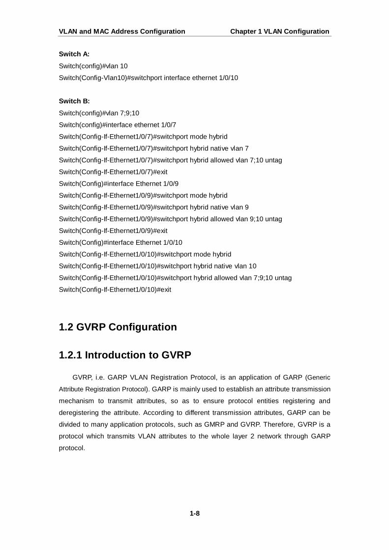
Fig 1-4 a typical application scene
A and G switches are not directly connected in layer 2 network; BCDEF are
intermediate switches connecting A and G. Switch A and G configure VLAN100-1000
manually while BCDEF switches do not. When GVRP is not enabled, A and G cannot
communicate with each other, because intermediate switches without relevant VLANs.
However, after GVRP is enabled on all switches, its VLAN attribute transmission
mechanism enables the intermediate switches registering the VLANs dynamically, and the
VLAN in VLAN100-1000 of A and G can communicate with each other. The VLANs
dynamically registered by intermediate switches will be deregistered when deregistering
VLAN100-1000 of A and G switches manually. So the same VLAN of two unadjacent
switches can communicate mutually through GVRP protocol instead of configuring each
intermediate switch manually for achieving the purpose of simplifying VLAN configuration.
1.2.2 GVRP Configuration Task List
GVRP configuration task list:
1. Configure GVRP timer
2. Configure port type
3. Enable GVRP function
1. Configure GVRP timer
Command Explanation
Global mode
VLAN and MAC Address Configuration Chapter 1 VLAN Configuration
1-10
2. Configure port type
3. Enable GVRP function
1.2.3 Example of GVRP
GVRP application:
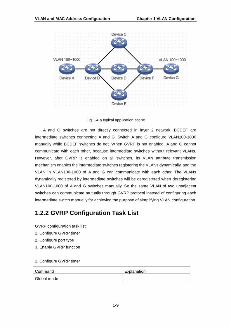
garp timer join <200-500> garp timer leave <500-1200> garp timer leaveall <5000-60000> no garp timer (join | leave | leaveAll)
Configure leaveall, join and leave
timer for GVRP.
Command Explanation
Port mode
gvrp no gvrp
Enable/ disable GVRP function of
port.
Command Explanation
Global mode
gvrp no gvrp
Enable/ disable the global GVRP
function of port.
VLAN and MAC Address Configuration Chapter 1 VLAN Configuration
1-11
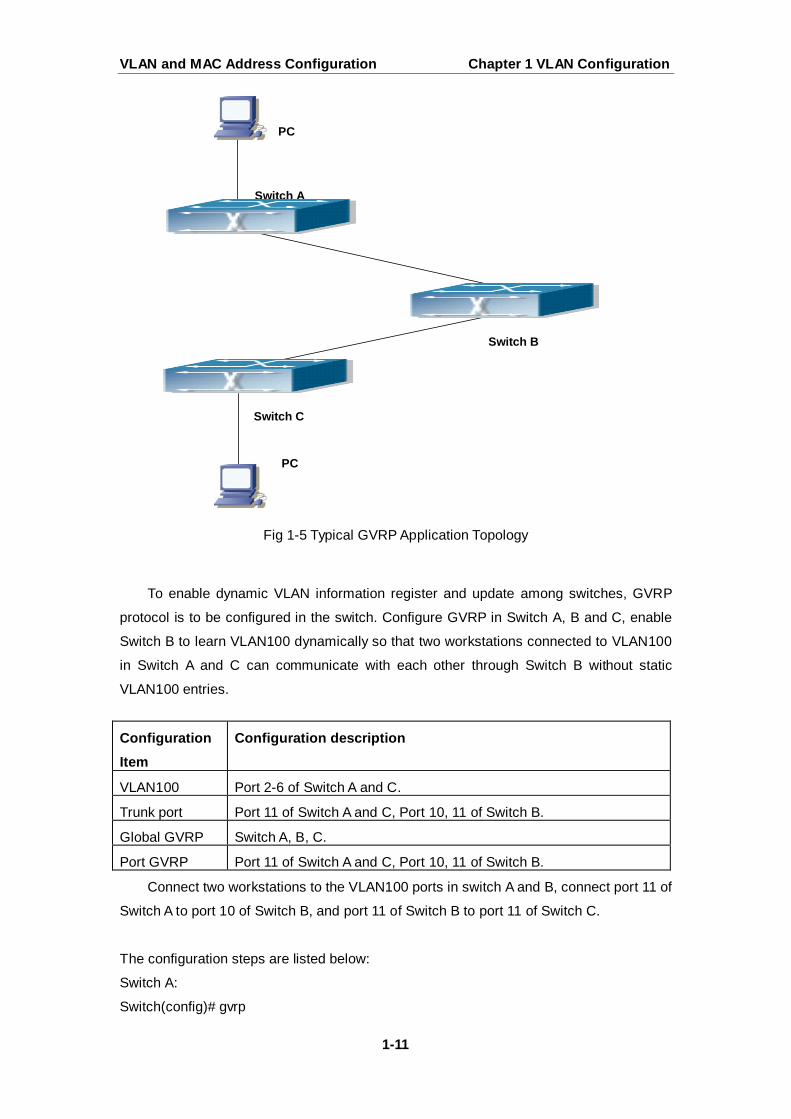
Fig 1-5 Typical GVRP Application Topology
To enable dynamic VLAN information register and update among switches, GVRP
protocol is to be configured in the switch. Configure GVRP in Switch A, B and C, enable
Switch B to learn VLAN100 dynamically so that two workstations connected to VLAN100
in Switch A and C can communicate with each other through Switch B without static
VLAN100 entries.
Configuration Item
Configuration description
VLAN100 Port 2-6 of Switch A and C.
Trunk port Port 11 of Switch A and C, Port 10, 11 of Switch B.
Global GVRP Switch A, B, C.
Port GVRP Port 11 of Switch A and C, Port 10, 11 of Switch B.
Connect two workstations to the VLAN100 ports in switch A and B, connect port 11 of
Switch A to port 10 of Switch B, and port 11 of Switch B to port 11 of Switch C.
The configuration steps are listed below:
Switch A: Switch(config)# gvrp
PC
PC
Switch A
Switch B
Switch C
VLAN and MAC Address Configuration Chapter 1 VLAN Configuration
1-12
Switch(config)#vlan 100
Switch(Config-Vlan100)#switchport interface ethernet 1/0/2-6
Switch(Config-Vlan100)#exit
Switch(config)#interface ethernet 1/0/11
Switch(Config-If-Ethernet1/0/11)#switchport mode trunk
Switch(Config-If-Ethernet1/0/11)# gvrp
Switch(Config-If-Ethernet1/0/11)#exit
Switch B: Switch(config)#gvrp
Switch(config)#interface ethernet 1/0/10
Switch(Config-If-Ethernet1/0/10)#switchport mode trunk
Switch(Config-If-Ethernet1/0/10)# gvrp
Switch(Config-If-Ethernet1/0/10)#exit
Switch(config)#interface ethernet 1/0/11
Switch(Config-If-Ethernet1/0/11)#switchport mode trunk
Switch(Config-If-Ethernet1/0/11)# gvrp
Switch(Config-If-Ethernet1/0/11)#exit
Switch C: Switch(config)# gvrp
Switch(config)#vlan 100
Switch(Config-Vlan100)#switchport interface ethernet 1/0/2-6
Switch(Config-Vlan100)#exit
Switch(config)#interface ethernet 1/0/11
Switch(Config-If-Ethernet1/0/11)#switchport mode trunk
Switch(Config-If-Ethernet1/0/11)# gvrp
Switch(Config-If-Ethernet1/0/11)#exit
1.2.4 GVRP Troubleshooting
The GARP counter setting for Trunk ports in both ends of Trunk link must be the
same, otherwise GVRP will not work normally. It is recommended to avoid enabling GVRP
and RSTP at the same time in switch. If GVRP needs to be enabled, RSTP function for the
ports must be disabled first.
VLAN and MAC Address Configuration Chapter 1 VLAN Configuration
1-13
1.3 Dot1q-tunnel Configuration
1.3.1 Introduction to Dot1q-tunnel
Dot1q-tunnel is also called QinQ (802.1Q-in-802.1Q), which is an expansion of
802.1Q. Its dominating idea is encapsulating the customer VLAN tag (CVLAN tag) to the
service provider VLAN tag (SPVLAN tag). Carrying the two VLAN tags the packet is
transmitted through the backbone network of the ISP internet, so to provide a simple
layer-2 tunnel for the users. It is simple and easy to manage, applicable only by static
configuration, and especially adaptive to small office network or small scale metropolitan
area network using layer-3 switch as backbone equipment.
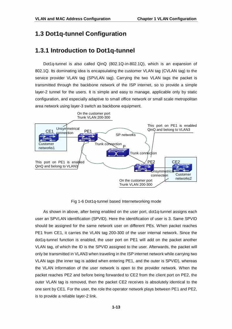
Fig 1-6 Dot1q-tunnel based Internetworking mode
As shown in above, after being enabled on the user port, dot1q-tunnel assigns each
user an SPVLAN identification (SPVID). Here the identification of user is 3. Same SPVID
should be assigned for the same network user on different PEs. When packet reaches
PE1 from CE1, it carries the VLAN tag 200-300 of the user internal network. Since the
dot1q-tunnel function is enabled, the user port on PE1 will add on the packet another
VLAN tag, of which the ID is the SPVID assigned to the user. Afterwards, the packet will
only be transmitted in VLAN3 when traveling in the ISP internet network while carrying two
VLAN tags (the inner tag is added when entering PE1, and the outer is SPVID), whereas
the VLAN information of the user network is open to the provider network. When the
packet reaches PE2 and before being forwarded to CE2 from the client port on PE2, the
outer VLAN tag is removed, then the packet CE2 receives is absolutely identical to the
one sent by CE1. For the user, the role the operator network plays between PE1 and PE2,
is to provide a reliable layer-2 link.
SP networks
P
PE1
PE2
CE1
CE2
Trunk connection
Trunk connection
Unsymmetrical connection
Unsymmetrical connection
Customer networks1
Customer networks2
On the customer port Trunk VLAN 200-300
This port on PE1 is enabled QinQ and belong to VLAN3
On the customer port Trunk VLAN 200-300
This port on PE1 is enabled QinQ and belong to VLAN3
VLAN and MAC Address Configuration Chapter 1 VLAN Configuration
1-14
The technology of Dot1q-tuunel provides the ISP internet the ability of supporting
many client VLANs by only one VLAN of theirselves. Both the ISP internet and the clients
can configure their own VLAN independently.
It is obvious that, the dot1q-tunnel function has got following characteristics:
Applicable through simple static configuration, no complex configuration or
maintenance to be needed.
Operators will only have to assign one SPVID for each user, which increases the
number of concurrent supportable users; while the users has got the ultimate
freedom in selecting and managing the VLAN IDs (select within 1~4096 at users’
will).
The user network is considerably independent. When the ISP internet is
upgrading their network, the user networks do not have to change their original
configuration.
Detailed description on the application and configuration of dot1q-tunnel will be
provided in this section.
1.3.2 Dot1q-tunnel Configuration
Configuration Task Sequence of Dot1q-Tunnel:
1. Configure the dot1q-tunnel function on port
2. Configure the protocol type (TPID) on port
1. Configure the dot1q-tunnel function on port
2. Configure the protocol type (TPID) on port
1.3.3 Typical Applications of the Dot1q-tunnel
Command Explanation
Port mode
dot1q-tunnel enable
no dot1q-tunnel enable Enter/exit the dot1q-tunnel mode on
the port.
Command Explanation
Port mode
dot1q-tunnel tpid {0x8100|0x9100|0x9200|<1-65535>}
Configure the protocol type on TRUNK
port.
VLAN and MAC Address Configuration Chapter 1 VLAN Configuration
1-15
Scenario:
Edge switch PE1 and PE2 of the ISP internet forward the VLAN200~300 data
between CE1 and CE2 of the client network with VLAN3. The port1 of PE1 is connected to
CE1, port10 is connected to public network, the TPID of the connected equipment is 9100;
port1 of PE2 is connected to CE2, port10 is connected to public network.
Configuration Item
Configuration Explanation
VLAN3 Port1 of PE1 and PE2.
dot1q-tunnel Port1 of PE1 and PE2.
tpid 9100
Configuration procedure is as follows:
PE1:
Switch(config)#vlan 3
Switch(Config-Vlan3)#switchport interface ethernet 1/0/1
Switch(Config-Vlan3)#exit
Switch(Config)#interface ethernet 1/0/1
Switch(Config-Ethernet1/0/1)# dot1q-tunnel enable
Switch(Config-Ethernet1/0/1)# exit
Switch(Config)#interface ethernet 1/0/10
Switch(Config-Ethernet1/0/10)#switchport mode trunk
Switch(Config-Ethernet1/0/10)#dot1q-tunnel tpid 0x9100
Switch(Config-Ethernet1/0/10)#exit
Switch(Config)#
PE2:
Switch(config)#vlan 3
Switch(Config-Vlan3)#switchport interface ethernet 1/0/1
Switch(Config-Vlan3)#exit
Switch(Config)#interface ethernet 1/0/1
Switch(Config-Ethernet1/0/1)# dot1q-tunnel enable
Switch(Config-Ethernet1/0/1)# exit
Switch(Config)#interface ethernet 1/0/10
Switch(Config-Ethernet1/0/10)#switchport mode trunk
Switch(Config-Ethernet1/0/10)#dot1q-tunnel tpid 0x9100
Switch(Config-Ethernet1/0/10)#exit
Switch(Config)#
VLAN and MAC Address Configuration Chapter 1 VLAN Configuration
1-16
1.3.4 Dot1q-tunnel Troubleshooting
Enabling dot1q-tunnel on Trunk port will make the tag of the data packet unpredictable
which is not required in the application. So it is not recommended to enable
dot1q-tunnel on Trunk port.
Enabled with STP/MSTP is not supported.
Enabled with PVLAN is not supported.
1.4 VLAN-translation Configuration
1.4.1 Introduction to VLAN-translation
VLAN translation, as one can tell from the name, which translates the original VLAN
ID to new VLAN ID according to the user requirements so to exchange data across
different VLANs. VLAN translation is classified to ingress translation and egress
translation, this switch only supports switchover of ingress for VLAN ID.
Application and configuration of VLAN translation will be explained in detail in this
section.
1.4.2 VLAN-translation Configuration
Configuration task sequence of VLAN-translation:
1. Configure the VLAN-translation function on the port
2. Configure the VLAN-translation relations on the port
3. Configure whether the packet is dropped when checking VLAN-translation is failing
4. Show the related configuration of vlan-translation
1. Configure the VLAN-translation of the port
2. Configure the VLAN-translation relation of the port
Command Explanation
Port mode
vlan-translation enable no vlan-translation enable
Enter/exit the port VLAN-translation
mode.
Command Explanation
Port mode
vlan-translation <old-vlan-id> to Add/delete a VLAN-translation relation.
VLAN and MAC Address Configuration Chapter 1 VLAN Configuration
1-17
3. Configure whether the packet is dropped when checking VLAN-translation is failing
4. Show the related configuration of vlan-translation
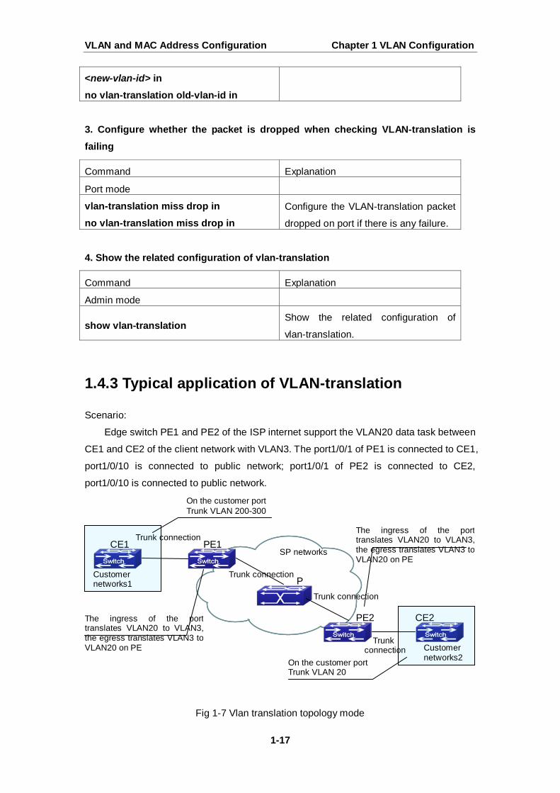
1.4.3 Typical application of VLAN-translation
Scenario:
Edge switch PE1 and PE2 of the ISP internet support the VLAN20 data task between
CE1 and CE2 of the client network with VLAN3. The port1/0/1 of PE1 is connected to CE1,
port1/0/10 is connected to public network; port1/0/1 of PE2 is connected to CE2,
port1/0/10 is connected to public network.
Fig 1-7 Vlan translation topology mode
<new-vlan-id> in no vlan-translation old-vlan-id in
Command Explanation
Port mode
vlan-translation miss drop in no vlan-translation miss drop in
Configure the VLAN-translation packet
dropped on port if there is any failure.
Command Explanation
Admin mode
show vlan-translation Show the related configuration of
vlan-translation.
SP networks
P
PE1
PE2
CE1
CE2
Trunk connection
Trunk connection
Trunk connection
Trunk connection
Customer networks1
Customer networks2
On the customer port Trunk VLAN 200-300
The ingress of the port translates VLAN20 to VLAN3, the egress translates VLAN3 to VLAN20 on PE
On the customer port Trunk VLAN 20
The ingress of the port translates VLAN20 to VLAN3, the egress translates VLAN3 to VLAN20 on PE

VLAN and MAC Address Configuration Chapter 1 VLAN Configuration
1-18
Configuration Item
Configuration Explanation
VLAN-translation Port1/0/1 of PE1 and PE2.
Trunk port Port1/0/1 and Port1/0/10 of PE1 and PE2.
Configuration procedure is as follows: PE1、PE2:
switch(Config)#interface ethernet 1/0/1
switch(Config-Ethernet1/0/1)#switchport mode trunk
switch(Config-Ethernet1/0/1)# vlan-translation enable
switch(Config-Ethernet1/0/1)# vlan-translation 20 to 3 in
switch(Config-Ethernet1/0/1)# vlan-translation 3 to 20 out
switch(Config-Ethernet1/0/1)# exit
switch(Config)#interface ethernet 1/0/10
switch(Config-Ethernet1/0/10)#switchport mode trunk
switch(Config-Ethernet1/0/10)#exit
switch(Config)#
1.4.4 VLAN-translation Troubleshooting
Normally the VLAN-translation is applied on trunk ports.
Priority of vlan translation and vlan ingress filtering for processing packets is: vlan
translation > vlan ingress filtering
1.5 Dynamic VLAN Configuration
1.5.1 Introduction to Dynamic VLAN
The dynamic VLAN is named corresponding to the static VLAN (namely the port
based VLAN). Dynamic VLAN supported by the switch includes MAC-based VLAN,
IP-subnet-based VLAN and Protocol-based VLAN. Detailed description is as follows:
The MAC-based VLAN division is based on the MAC address of each host, namely
every host with a MAC address will be assigned to certain VLAN. By the means, the
network user will maintain his membership in his belonging VLAN when moves from a
physical location to another. As we can see the greatest advantage of this VLAN division
is that the VLAN does not have to be re-configured when the user physic location change,
namely shift from one switch to another, which is because it is user based, not switch port
VLAN and MAC Address Configuration Chapter 1 VLAN Configuration
1-19
based.
The IP subnet based VLAN is divided according to the source IP address and its
subnet mask of every host. It assigns corresponding VLAN ID to the data packet
according to the subnet segment, leading the data packet to specified VLAN. Its
advantage is the same as that of the MAC-based VLAN: the user does not have to change
configuration when relocated.
The VLAN is divided by the network layer protocol, assigning different protocol to
different VLANs. This is very attractive to the network administrators who wish to organize
the user by applications and services. Moreover the user can move freely within the
network while maintaining his membership. Advantage of this method enables user to
change physical position without changing their VLAN residing configuration, while the
VLAN can be divided by types of protocols which is important to the network
administrators. Further, this method has no need of added frame label to identify the
VLAN which reduce the network traffic.
Notice: Dynamic VLAN needs to associate with Hybrid attribute of the ports to work,
so the ports that may be added to a dynamic VLAN must be configured as Hybrid port.
1.5.2 Dynamic VLAN Configuration
Dynamic VLAN Configuration Task Sequence:
1. Configure the MAC-based VLAN function on the port
2. Set the VLAN to MAC VLAN
3. Configure the correspondence between the MAC address and the VLAN
4. Configure the IP-subnet-based VLAN function on the port
5. Configure the correspondence between the IP subnet and the VLAN
6. Configure the correspondence between the Protocols and the VLAN
7. Adjust the priority of the dynamic VLAN
1. Configure the MAC-based VLAN function on the port
2. Set the VLAN to MAC VLAN
Command Explanation
Port Mode
switchport mac-vlan enable no switchport mac-vlan enable
Enable/disable the MAC-based VLAN
function on the port.
Command Explanation
Global Mode
VLAN and MAC Address Configuration Chapter 1 VLAN Configuration
1-20
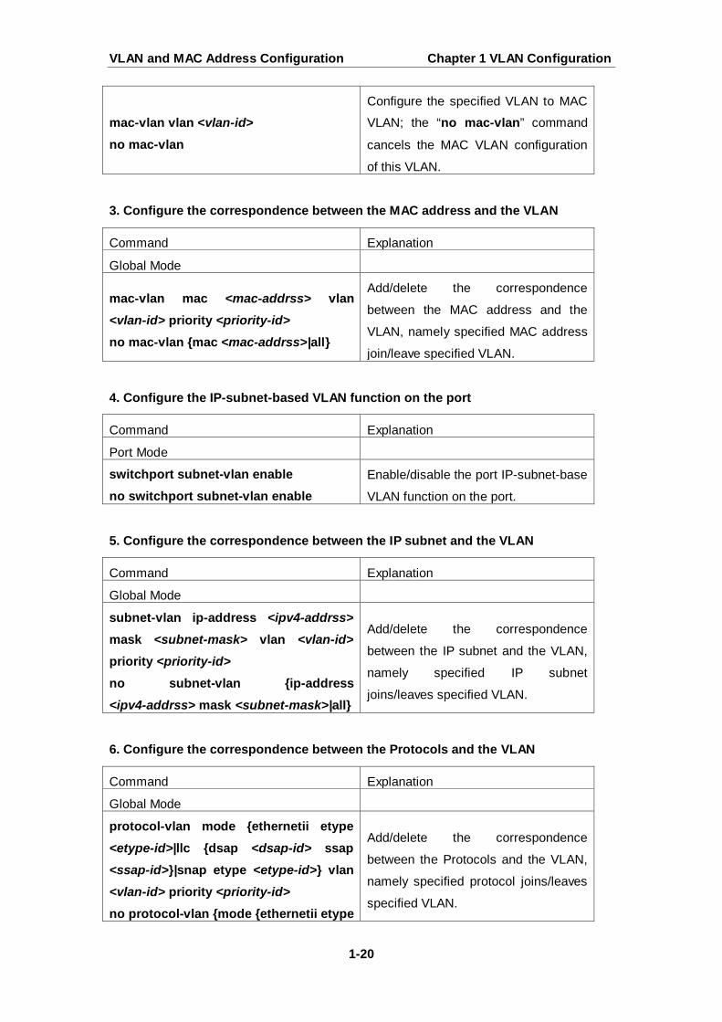
3. Configure the correspondence between the MAC address and the VLAN
4. Configure the IP-subnet-based VLAN function on the port
5. Configure the correspondence between the IP subnet and the VLAN
6. Configure the correspondence between the Protocols and the VLAN
mac-vlan vlan <vlan-id> no mac-vlan
Configure the specified VLAN to MAC
VLAN; the “no mac-vlan” command
cancels the MAC VLAN configuration
of this VLAN.
Command Explanation
Global Mode
mac-vlan mac <mac-addrss> vlan <vlan-id> priority <priority-id> no mac-vlan {mac <mac-addrss>|all}
Add/delete the correspondence
between the MAC address and the
VLAN, namely specified MAC address
join/leave specified VLAN.
Command Explanation
Port Mode
switchport subnet-vlan enable no switchport subnet-vlan enable
Enable/disable the port IP-subnet-base
VLAN function on the port.
Command Explanation
Global Mode
subnet-vlan ip-address <ipv4-addrss> mask <subnet-mask> vlan <vlan-id> priority <priority-id> no subnet-vlan {ip-address <ipv4-addrss> mask <subnet-mask>|all}
Add/delete the correspondence
between the IP subnet and the VLAN,
namely specified IP subnet
joins/leaves specified VLAN.
Command Explanation
Global Mode
protocol-vlan mode {ethernetii etype <etype-id>|llc {dsap <dsap-id> ssap <ssap-id>}|snap etype <etype-id>} vlan <vlan-id> priority <priority-id>
no protocol-vlan {mode {ethernetii etype
Add/delete the correspondence
between the Protocols and the VLAN,
namely specified protocol joins/leaves
specified VLAN.

VLAN and MAC Address Configuration Chapter 1 VLAN Configuration
1-21
7. Adjust the priority of the dynamic VLAN
1.5.3 Typical Application of the Dynamic VLAN
Scenario:
In the office network Department A belongs to VLAN100. Several members of this
department often have the need to move within the whole office network. It is also
required to ensure the resource for other members of the department to access VLAN 100.
Assume one of the members is M, the MAC address of his PC is 00-03-0f-11-22-33, when
M moves to VLAN200 or VLAN300, the port connecting M is configured as Hybrid mode
and belongs to VLAN100 with untag mode. In this way, the data of VLAN100 will be
forwarded to the port connecting M, and implement the communication requirement in
VLAN100.
Fig 1-8 Typical topology application of dynamic VLAN
<etype-id>|llc {dsap <dsap-id> ssap <ssap-id>}|snap etype <etype-id>}|all}
Command Explanation
Global Mode
dynamic-vlan mac-vlan prefer dynamic-vlan subnet-vlan prefer
Configure the priority of the dynamic
VLAN.
SwitchA SwitchB SwitchC
VLAN100
VLAN200
VLAN300 M
VLAN and MAC Address Configuration Chapter 1 VLAN Configuration
1-22
Configuration Items
Configuration Explanation
MAC-based
VLAN
Global configuration on Switch A, Switch B, Switch C.
For example, M at E1/0/1 of SwitchA, then the configuration procedures are as follows:
Switch A, Switch B, Switch C:
SwitchA (Config)#mac-vlan mac 00-03 -0f-11-22-33 vlan 100 priority 0
SwitchA (Config)#interface ethernet 1/0/1
SwitchA (Config-Ethernet1/0/1)# swportport mode hybrid
SwitchA (Config-Ethernet1/0/1)# swportport hybrid allowed vlan 100 untagged
SwitchB (Config)#mac-vlan mac 00-03-0f-11-22-33 vlan 100 priority 0
SwitchB (Config)#exit
SwitchB#
SwitchC (Config)#mac-vlan mac 00-03-0f-11-22-33 vlan 100 priority 0
SwitchC (Config)#exit
SwitchC#
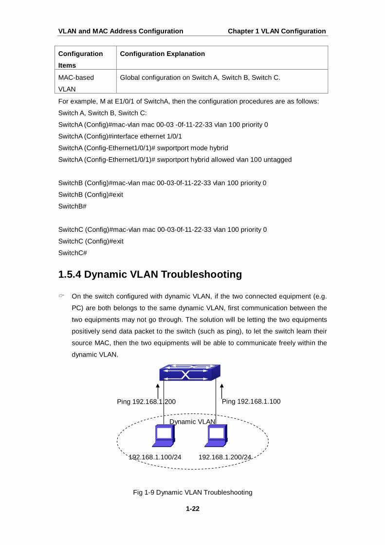
1.5.4 Dynamic VLAN Troubleshooting
On the switch configured with dynamic VLAN, if the two connected equipment (e.g.
PC) are both belongs to the same dynamic VLAN, first communication between the
two equipments may not go through. The solution will be letting the two equipments
positively send data packet to the switch (such as ping), to let the switch learn their
source MAC, then the two equipments will be able to communicate freely within the
dynamic VLAN.
Fig 1-9 Dynamic VLAN Troubleshooting
192.168.1.100/24 192.168.1.200/24
Ping 192.168.1.100 Ping 192.168.1.200
Dynamic VLAN
VLAN and MAC Address Configuration Chapter 1 VLAN Configuration
1-23
Priority of dynamic vlan and vlan ingress filtering for processing packets is: dynamic
vlan> vlan ingress filtering
1.6 Voice VLAN Configuration
1.6.1 Introduction to Voice VLAN
Voice VLAN is specially configured for the user voice data traffic. By setting a Voice
VLAN and adding the ports of the connected voice equipments to the Voice VLAN, the
user will be able to configure QoS (Quality of service) service for voice data, and improve
the voice data traffic transmission priority to ensure the calling quality.
The switch can judge if the data traffic is the voice data traffic from specified
equipment according to the source MAC address field of the data packet entering the port.
The packet with the source MAC address complying with the system defined voice
equipment OUI (Organizationally Unique Identifier) will be considered the voice data traffic
and transmitted to the Voice VLAN.
The configuration is based on MAC address, acquiring a mechanism in which every
voice equipment transmitting information through the network has got its unique MAC
address. VLAN will trace the address belongs to specified MAC. By This means, VLAN
allows the voice equipment always belong to Voice VLAN when relocated physically. The
greatest advantage of the VLAN is the equipment can be automatically placed into Voice
VLAN according to its voice traffic which will be transmitted at specified priority. Meanwhile,
when voice equipment is physically relocated, it still belongs to the Voice VLAN without
any further configuration modification, which is because it is based on voice equipment
other than switch port.
Notice: Voice VLAN needs to associate with Hybrid attribute of the ports to work, so
the ports that may be added to Voice VLAN must be configured as Hybrid port.
1.6.2 Voice VLAN Configuration
Voice VLAN Configuration Task Sequence:
1. Set the VLAN to Voice VLAN
2. Add a voice equipment to Voice VLAN
3. Enable the Voice VLAN on the port
1. Configure the VLAN to Voice VLAN
Command Explanation
Global Mode
VLAN and MAC Address Configuration Chapter 1 VLAN Configuration
1-24
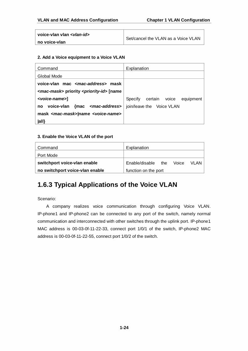
2. Add a Voice equipment to a Voice VLAN
3. Enable the Voice VLAN of the port
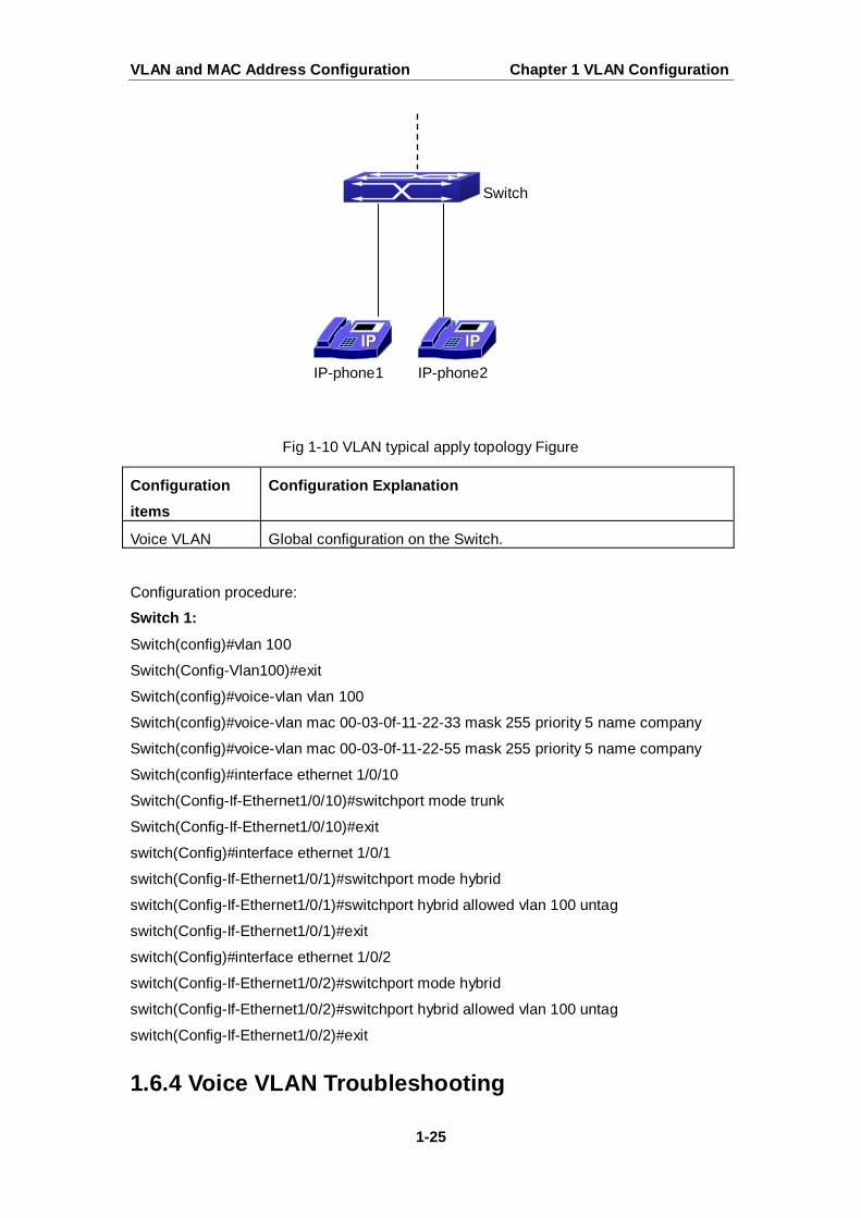
1.6.3 Typical Applications of the Voice VLAN
Scenario:
A company realizes voice communication through configuring Voice VLAN.
IP-phone1 and IP-phone2 can be connected to any port of the switch, namely normal
communication and interconnected with other switches through the uplink port. IP-phone1
MAC address is 00-03-0f-11-22-33, connect port 1/0/1 of the switch, IP-phone2 MAC
address is 00-03-0f-11-22-55, connect port 1/0/2 of the switch.
voice-vlan vlan <vlan-id> no voice-vlan
Set/cancel the VLAN as a Voice VLAN
Command Explanation
Global Mode
voice-vlan mac <mac-address> mask <mac-mask> priority <priority-id> [name <voice-name>] no voice-vlan {mac <mac-address> mask <mac-mask>|name <voice-name> |all}
Specify certain voice equipment
join/leave the Voice VLAN
Command Explanation
Port Mode
switchport voice-vlan enable no switchport voice-vlan enable
Enable/disable the Voice VLAN
function on the port
VLAN and MAC Address Configuration Chapter 1 VLAN Configuration
1-25
Fig 1-10 VLAN typical apply topology Figure
Configuration items
Configuration Explanation
Voice VLAN Global configuration on the Switch.
Configuration procedure:
Switch 1:
Switch(config)#vlan 100
Switch(Config-Vlan100)#exit
Switch(config)#voice-vlan vlan 100
Switch(config)#voice-vlan mac 00-03-0f-11-22-33 mask 255 priority 5 name company
Switch(config)#voice-vlan mac 00-03-0f-11-22-55 mask 255 priority 5 name company
Switch(config)#interface ethernet 1/0/10
Switch(Config-If-Ethernet1/0/10)#switchport mode trunk
Switch(Config-If-Ethernet1/0/10)#exit
switch(Config)#interface ethernet 1/0/1
switch(Config-If-Ethernet1/0/1)#switchport mode hybrid
switch(Config-If-Ethernet1/0/1)#switchport hybrid allowed vlan 100 untag
switch(Config-If-Ethernet1/0/1)#exit
switch(Config)#interface ethernet 1/0/2
switch(Config-If-Ethernet1/0/2)#switchport mode hybrid
switch(Config-If-Ethernet1/0/2)#switchport hybrid allowed vlan 100 untag
switch(Config-If-Ethernet1/0/2)#exit
1.6.4 Voice VLAN Troubleshooting
IP-phone1 IP-phone2
Switch
VLAN and MAC Address Configuration Chapter 1 VLAN Configuration
1-26
Voice VLAN can not be applied concurrently with MAC-base VLAN.
The Voice VLAN on the port is enabled by default. If the configured data can no
longer enter the Voice VLAN during operation, please check if the Voice VLAN
function has been disabled on the port.
1.7 Multi-to-One VLAN Translation Configuration
1.7.1 Introduction to Multi-to-One VLAN Translation
Multi-to-One VLAN translation, it translates the original VLAN ID into the new VLAN
ID according to user’s requirement on uplink traffic, and restores the original VLAN ID on
downlink traffic.
Application and configuration of Multi-to-One VLAN translation will be explained in
detail in this section.
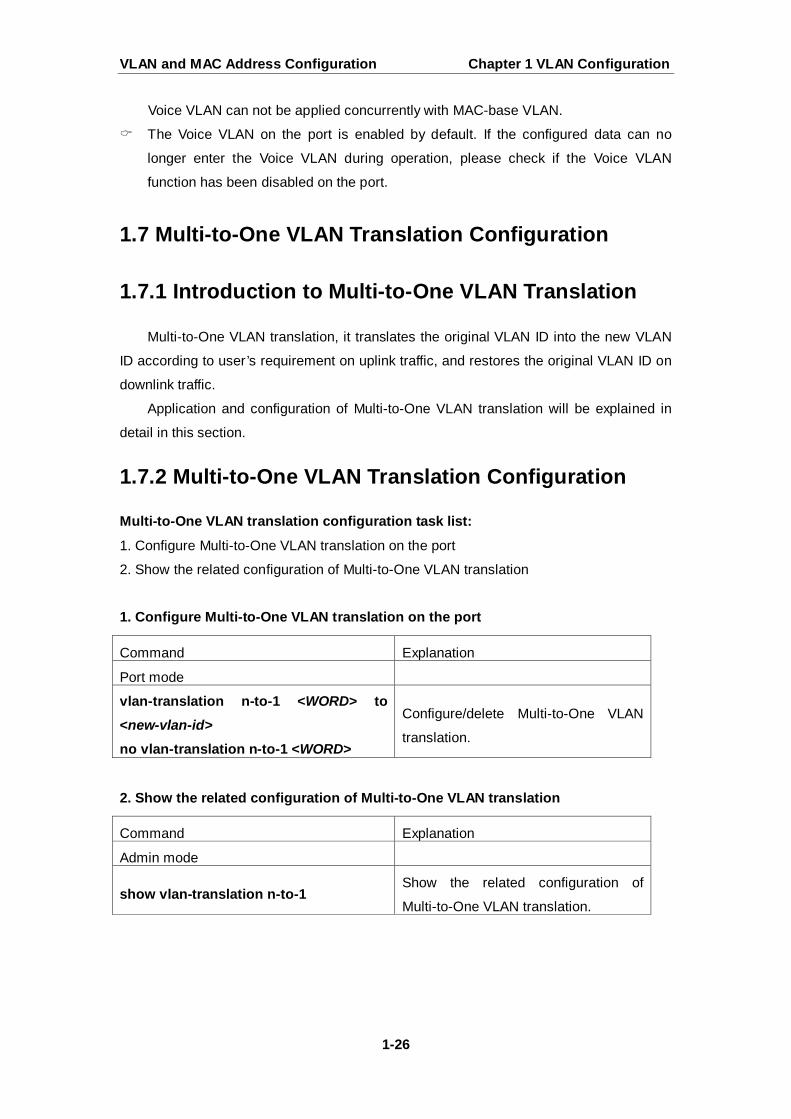
1.7.2 Multi-to-One VLAN Translation Configuration
Multi-to-One VLAN translation configuration task list:
1. Configure Multi-to-One VLAN translation on the port
2. Show the related configuration of Multi-to-One VLAN translation
1. Configure Multi-to-One VLAN translation on the port
2. Show the related configuration of Multi-to-One VLAN translation
Command Explanation
Port mode
vlan-translation n-to-1 <WORD> to <new-vlan-id> no vlan-translation n-to-1 <WORD>
Configure/delete Multi-to-One VLAN
translation.
Command Explanation
Admin mode
show vlan-translation n-to-1 Show the related configuration of
Multi-to-One VLAN translation.

VLAN and MAC Address Configuration Chapter 1 VLAN Configuration
1-27
1.7.3 Typical application of Multi-to-One VLAN
Translation
Scenario: UserA, userB and userC belong to VLAN1, VLAN2, VLAN3 respectively. Before
entering the network layer, data traffic of userA, userB and userC is translated into VLAN
100 by Ethernet1/0/1 of edge switch1. Contrarily, data traffic of userA, userB and userC
will be translated into VLAN1, VLAN2, VLAN3 by Ethernet1/0/1 of edge switch1 from
network layer respectively. In the same way, it implements multi-to-one translation for
userD, userE and userF on Ethernet1/0/1 of edge switch2.
Fig 1-11 VLAN-translation typical application
Configuration Item Configuration Explanation
VLAN Switch1、Switch2
Trunk Port Downlink port 1/0/1 and uplink port 1/0/5 of Switch1 and Switch
2
Multi-to-One
VLAN-translation
Downlink port 1/0/1 of Switch1 and Switch2
peixn
图章
VLAN and MAC Address Configuration Chapter 1 VLAN Configuration
1-28
Configuration procedure is as follows: Switch1、Switch2:
switch(Config)# vlan 1-3;100
switch(Config-Ethernet1/0/1)#switchport mode trunk
switch(Config-Ethernet1/0/1)# vlan-translation n-to-1 1-3 to 100
switch(Config)#interface ethernet 1/0/5
switch(Config-Ethernet1/0/5)#switchport mode trunk
switch(Config-Ethernet1/0/5)#exit
1.7.4 Multi-to-One VLAN Translation Troubleshooting
Do not be used with Dot1q-tunnel at the same time.
Do not be used with VLAN-translation at the same time.
The same MAC address should not exist in the original and the translated VLAN.
Check whether the hardware resource of the chip is able to ensure all clients to work
normally.
Limit learning of MAC address may affect Multi-to-One VLAN Translation.
Multi-to-One VLAN Translation should be enabled after MAC learning.
1.8 Super VLAN Configuration
1.8.1 Introduction to Super VLAN
Super VLAN, also called VLAN aggregation, we introduce the notion of super VLAN
and sub VLAN. One or more sub VLANs belong to a super VLAN, and sub VLAN does not
occupy an absolute subnet segment any more. However, in the same super VLAN,
whether host belongs to any sub VLAN, its IP address is within the subnet segment
associated with super VLAN.
In LanSwitch network, VLAN technique is applied widely for advantages (flexible
control of broadcast domain and deploy convenience). However, in generic layer-3 switch,
it implements communication between broadcast domains through a method that a VLAN
correspond to a layer-3 interface, it results in IP address waste.
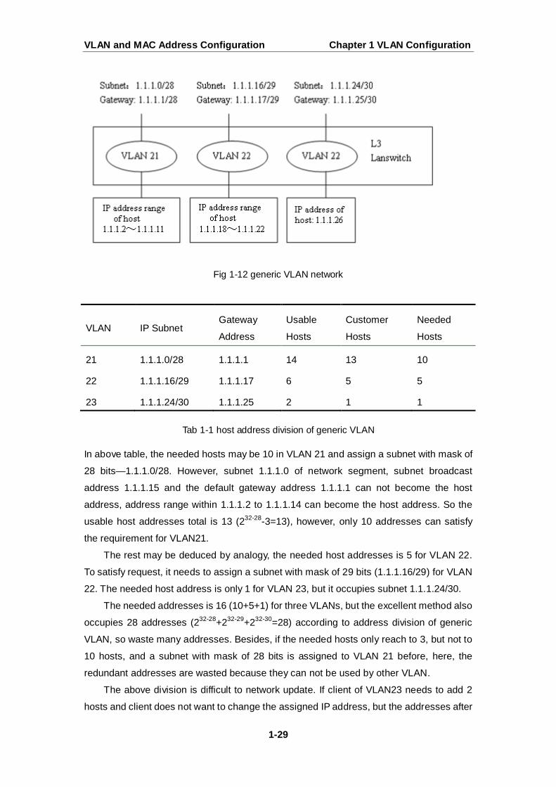
For example, VLAN division of device is shown in the figure.
VLAN and MAC Address Configuration Chapter 1 VLAN Configuration
1-29
Fig 1-12 generic VLAN network
VLAN IP Subnet Gateway
Address
Usable
Hosts
Customer
Hosts
Needed
Hosts
21 1.1.1.0/28 1.1.1.1 14 13 10
22 1.1.1.16/29 1.1.1.17 6 5 5
23 1.1.1.24/30 1.1.1.25 2 1 1
Tab 1-1 host address division of generic VLAN
In above table, the needed hosts may be 10 in VLAN 21 and assign a subnet with mask of
28 bits—1.1.1.0/28. However, subnet 1.1.1.0 of network segment, subnet broadcast
address 1.1.1.15 and the default gateway address 1.1.1.1 can not become the host
address, address range within 1.1.1.2 to 1.1.1.14 can become the host address. So the
usable host addresses total is 13 (232-28-3=13), however, only 10 addresses can satisfy
the requirement for VLAN21.
The rest may be deduced by analogy, the needed host addresses is 5 for VLAN 22.
To satisfy request, it needs to assign a subnet with mask of 29 bits (1.1.1.16/29) for VLAN
22. The needed host address is only 1 for VLAN 23, but it occupies subnet 1.1.1.24/30.
The needed addresses is 16 (10+5+1) for three VLANs, but the excellent method also
occupies 28 addresses (232-28+232-29+232-30=28) according to address division of generic
VLAN, so waste many addresses. Besides, if the needed hosts only reach to 3, but not to
10 hosts, and a subnet with mask of 28 bits is assigned to VLAN 21 before, here, the
redundant addresses are wasted because they can not be used by other VLAN.
The above division is difficult to network update. If client of VLAN23 needs to add 2
hosts and client does not want to change the assigned IP address, but the addresses after
VLAN and MAC Address Configuration Chapter 1 VLAN Configuration
1-30
1.1.1.24 are assigned to others, so we should assign a subnet with mask of 29 bits and a
new VLAN to this client. Here, there are 3 hosts for client of VLAN23 only, but this client is
assigned two subnets (they are not in the same VLAN), therefore, it is difficult to
management.
We can see that the number of the wasting IP address (such as subnet number,
broadcast address, default gateway address) is considerable and badly reduce the
addressing flexility that waste many addresses. Therefore, Super VLAN is developed for
solving the problem.
Super VLAN advantages are shown in the following:
Reduce IP address number about subnet number, default gateway address and broadcast
address
Implement that the different broadcast domains use addresses of the same subnet
segment
Enhance addressing flexility
Reduce the address waste
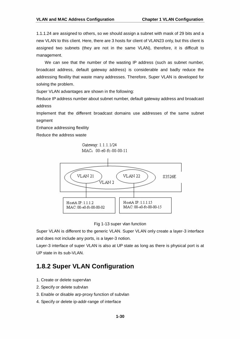
Fig 1-13 super vlan function
Super VLAN is different to the generic VLAN. Super VLAN only create a layer-3 interface
and does not include any ports, is a layer-3 notion.
Layer-3 interface of super VLAN is also at UP state as long as there is physical port is at
UP state in its sub-VLAN.
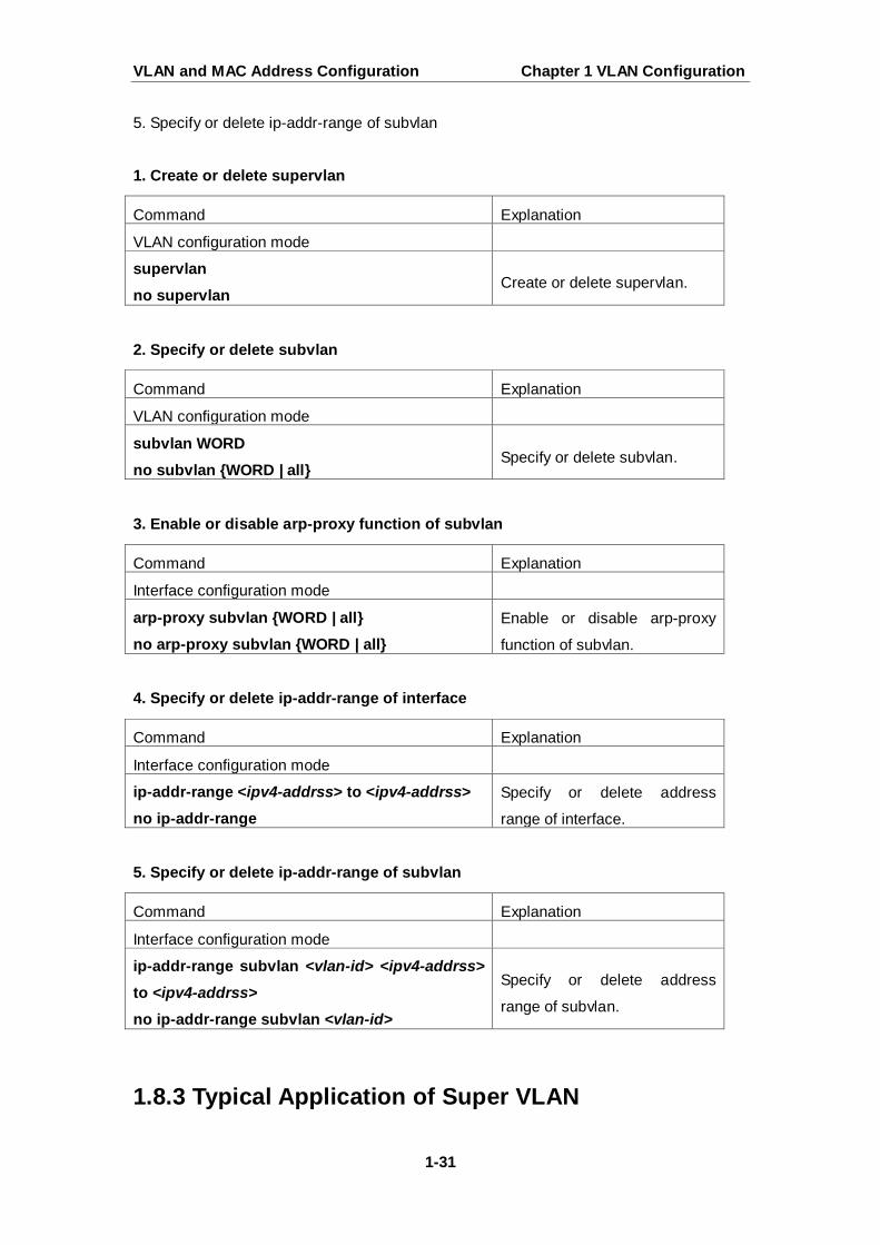
1.8.2 Super VLAN Configuration
1. Create or delete supervlan
2. Specify or delete subvlan
3. Enable or disable arp-proxy function of subvlan
4. Specify or delete ip-addr-range of interface
VLAN and MAC Address Configuration Chapter 1 VLAN Configuration
1-31
5. Specify or delete ip-addr-range of subvlan
1. Create or delete supervlan
2. Specify or delete subvlan
3. Enable or disable arp-proxy function of subvlan
4. Specify or delete ip-addr-range of interface
5. Specify or delete ip-addr-range of subvlan
1.8.3 Typical Application of Super VLAN
Command Explanation
VLAN configuration mode
supervlan no supervlan
Create or delete supervlan.
Command Explanation
VLAN configuration mode
subvlan WORD no subvlan {WORD | all}
Specify or delete subvlan.
Command Explanation
Interface configuration mode
arp-proxy subvlan {WORD | all} no arp-proxy subvlan {WORD | all}
Enable or disable arp-proxy
function of subvlan.
Command Explanation
Interface configuration mode
ip-addr-range <ipv4-addrss> to <ipv4-addrss> no ip-addr-range
Specify or delete address
range of interface.
Command Explanation
Interface configuration mode
ip-addr-range subvlan <vlan-id> <ipv4-addrss>
to <ipv4-addrss> no ip-addr-range subvlan <vlan-id>
Specify or delete address
range of subvlan.
VLAN and MAC Address Configuration Chapter 1 VLAN Configuration
1-32
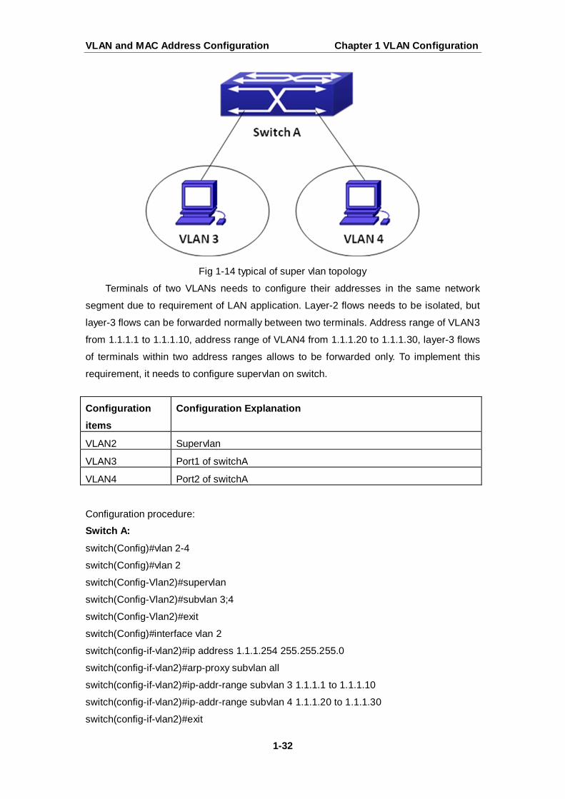
Fig 1-14 typical of super vlan topology
Terminals of two VLANs needs to configure their addresses in the same network
segment due to requirement of LAN application. Layer-2 flows needs to be isolated, but
layer-3 flows can be forwarded normally between two terminals. Address range of VLAN3
from 1.1.1.1 to 1.1.1.10, address range of VLAN4 from 1.1.1.20 to 1.1.1.30, layer-3 flows
of terminals within two address ranges allows to be forwarded only. To implement this
requirement, it needs to configure supervlan on switch.
Configuration items
Configuration Explanation
VLAN2 Supervlan
VLAN3 Port1 of switchA
VLAN4 Port2 of switchA
Configuration procedure:
Switch A:
switch(Config)#vlan 2-4
switch(Config)#vlan 2
switch(Config-Vlan2)#supervlan
switch(Config-Vlan2)#subvlan 3;4
switch(Config-Vlan2)#exit
switch(Config)#interface vlan 2
switch(config-if-vlan2)#ip address 1.1.1.254 255.255.255.0
switch(config-if-vlan2)#arp-proxy subvlan all
switch(config-if-vlan2)#ip-addr-range subvlan 3 1.1.1.1 to 1.1.1.10
switch(config-if-vlan2)#ip-addr-range subvlan 4 1.1.1.20 to 1.1.1.30
switch(config-if-vlan2)#exit
VLAN and MAC Address Configuration Chapter 1 VLAN Configuration
1-33
1.8.4 Super VLAN Troubleshooting
Supervlan and these functions (VRRP, dynamic VLAN, private VLAN, multicast VLAN,
etc.) are mutually exclusive, so they should not be used at the same time.
arp-proxy of subvlan takes effect to only one subvlan. Flow received by VLAN with
arp-proxy can be forwarded to other VLAN. When two devices send flows to each
other at different subvlan, please enable arp-proxy function on two subvlans.
Sub vlan can not set layer-3 interface.
When creating/deleting supervlan, VLAN needs to ensure no layer-3 interface, if not,
it will result in error.
If interface of supervlan specifies IP address range, but do not specify address range
of subvlan, address range set by interface is standard. If both interface and subvlan
specify IP address range, please check whether packets are within subvlan address
range firstly, second, check whether packets are within interface address range. After
that, packets can be processed other operations.
When setting supervlan or subvlan, VLAN must be exist, it can be set.
When port mode is set as trunk, it will automatically filter supervlan from allow-vlan.
VLAN and MAC Address Configuration Chapter 2 MAC Table Configuration
2-1
Chapter 2 MAC Table Configuration
2.1 Introduction to MAC Table
MAC table is a table identifies the mapping relationship between destination MAC
addresses and switch ports. MAC addresses can be categorized as static MAC addresses
and dynamic MAC addresses. Static MAC addresses are manually configured by the user,
have the highest priority and are permanently effective (will not be overwritten by dynamic
MAC addresses); dynamic MAC addresses are entries learnt by the switch in data frame
forwarding, and is effective for a limited period. When the switch receives a data frame to
be forwarded, it stores the source MAC address of the data frame and creates a mapping
to the destination port. Then the MAC table is queried for the destination MAC address, if
hit, the data frame is forwarded in the associated port, otherwise, the switch forwards the
data frame to its broadcast domain. If a dynamic MAC address is not learnt from the data
frames to be forwarded for a long time, the entry will be deleted from the switch MAC
table.
There are two MAC table operations:
1. Obtain a MAC address.
2. Forward or filter data frame according to the MAC table.
2.1.1 Obtaining MAC Table
The MAC table can be built up statically and dynamically. Static configuration is to set
up a mapping between the MAC addresses and the ports; dynamic learning is the process
in which the switch learns the mapping between MAC addresses and ports, and updates
the MAC table regularly. In this section, we will focus on the dynamic learning process of
MAC table.
VLAN and MAC Address Configuration Chapter 2 MAC Table Configuration
2-2
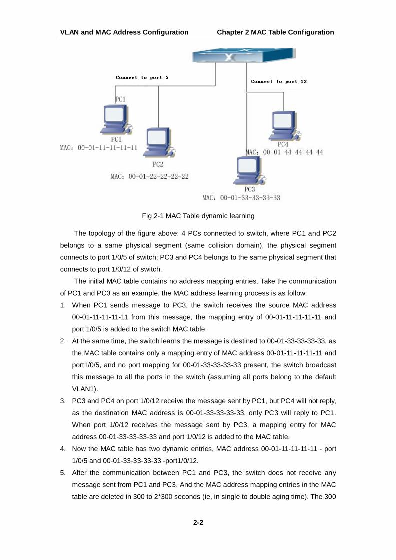
Fig 2-1 MAC Table dynamic learning
The topology of the figure above: 4 PCs connected to switch, where PC1 and PC2
belongs to a same physical segment (same collision domain), the physical segment
connects to port 1/0/5 of switch; PC3 and PC4 belongs to the same physical segment that
connects to port 1/0/12 of switch.
The initial MAC table contains no address mapping entries. Take the communication
of PC1 and PC3 as an example, the MAC address learning process is as follow:
1. When PC1 sends message to PC3, the switch receives the source MAC address
00-01-11-11-11-11 from this message, the mapping entry of 00-01-11-11-11-11 and
port 1/0/5 is added to the switch MAC table.
2. At the same time, the switch learns the message is destined to 00-01-33-33-33-33, as
the MAC table contains only a mapping entry of MAC address 00-01-11-11-11-11 and
port1/0/5, and no port mapping for 00-01-33-33-33-33 present, the switch broadcast
this message to all the ports in the switch (assuming all ports belong to the default
VLAN1).
3. PC3 and PC4 on port 1/0/12 receive the message sent by PC1, but PC4 will not reply,
as the destination MAC address is 00-01-33-33-33-33, only PC3 will reply to PC1.
When port 1/0/12 receives the message sent by PC3, a mapping entry for MAC
address 00-01-33-33-33-33 and port 1/0/12 is added to the MAC table.
4. Now the MAC table has two dynamic entries, MAC address 00-01-11-11-11-11 - port
1/0/5 and 00-01-33-33-33-33 -port1/0/12.
5. After the communication between PC1 and PC3, the switch does not receive any
message sent from PC1 and PC3. And the MAC address mapping entries in the MAC
table are deleted in 300 to 2*300 seconds (ie, in single to double aging time). The 300
VLAN and MAC Address Configuration Chapter 2 MAC Table Configuration
2-3
seconds here is the default aging time for MAC address entry in switch. Aging time
can be modified in switch.
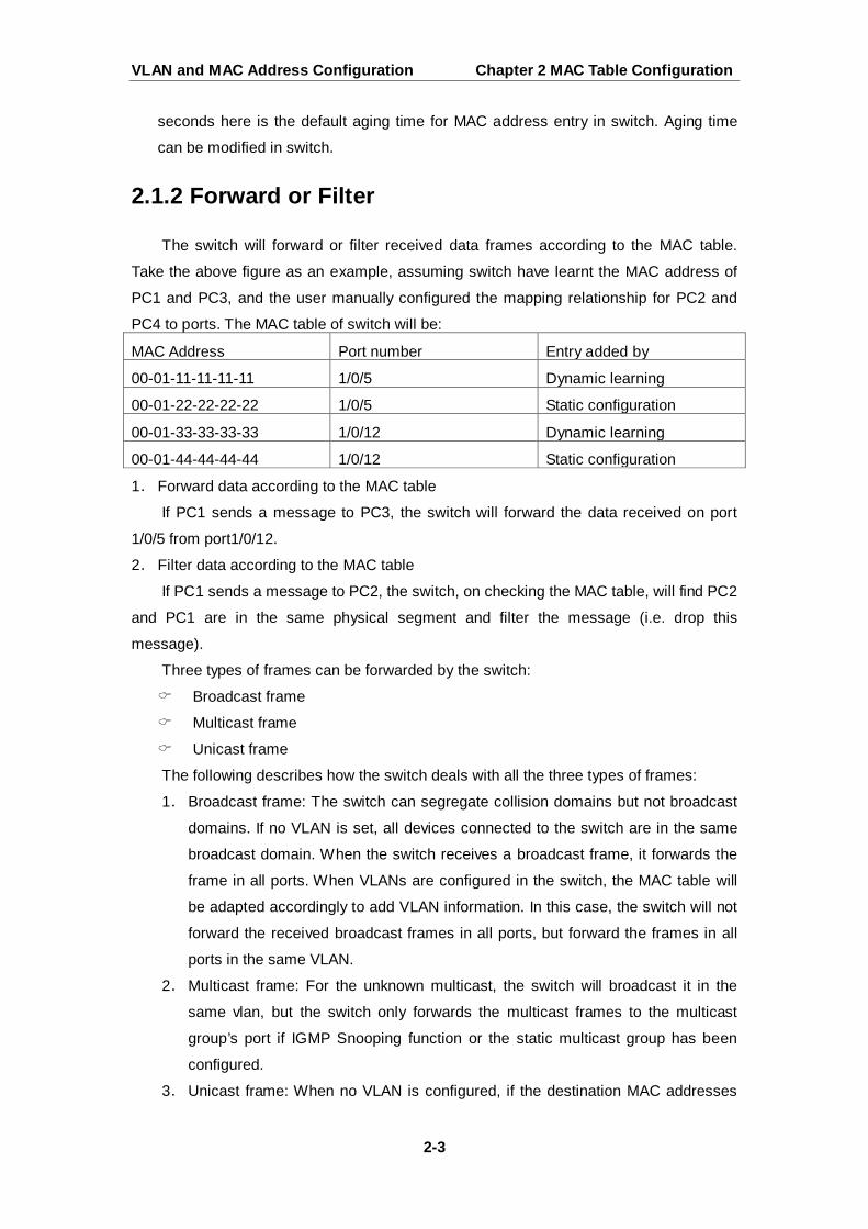
2.1.2 Forward or Filter
The switch will forward or filter received data frames according to the MAC table.
Take the above figure as an example, assuming switch have learnt the MAC address of
PC1 and PC3, and the user manually configured the mapping relationship for PC2 and
PC4 to ports. The MAC table of switch will be:
MAC Address Port number Entry added by
00-01-11-11-11-11 1/0/5 Dynamic learning
00-01-22-22-22-22 1/0/5 Static configuration
00-01-33-33-33-33 1/0/12 Dynamic learning
00-01-44-44-44-44 1/0/12 Static configuration
1. Forward data according to the MAC table
If PC1 sends a message to PC3, the switch will forward the data received on port
1/0/5 from port1/0/12.
2. Filter data according to the MAC table
If PC1 sends a message to PC2, the switch, on checking the MAC table, will find PC2
and PC1 are in the same physical segment and filter the message (i.e. drop this
message).
Three types of frames can be forwarded by the switch:
Broadcast frame
Multicast frame
Unicast frame
The following describes how the switch deals with all the three types of frames:
1. Broadcast frame: The switch can segregate collision domains but not broadcast
domains. If no VLAN is set, all devices connected to the switch are in the same
broadcast domain. When the switch receives a broadcast frame, it forwards the
frame in all ports. When VLANs are configured in the switch, the MAC table will
be adapted accordingly to add VLAN information. In this case, the switch will not
forward the received broadcast frames in all ports, but forward the frames in all
ports in the same VLAN.
2. Multicast frame: For the unknown multicast, the switch will broadcast it in the
same vlan, but the switch only forwards the multicast frames to the multicast
group’s port if IGMP Snooping function or the static multicast group has been
configured.
3. Unicast frame: When no VLAN is configured, if the destination MAC addresses
VLAN and MAC Address Configuration Chapter 2 MAC Table Configuration
2-4
are in the switch MAC table, the switch will directly forward the frames to the
associated ports; when the destination MAC address in a unicast frame is not
found in the MAC table, the switch will broadcast the unicast frame. When VLANs
are configured, the switch will forward unicast frame within the same VLAN. If the
destination MAC address is found in the MAC table but belonging to different
VLANs, the switch can only broadcast the unicast frame in the VLAN it belongs
to.
2.2 Mac Address Table Configuration Task List
1. Configure the MAC address aging-time
2. Configure static MAC forwarding or filter entry
3. Clear dynamic address table
4. Configure MAC learning through CPU control
1. Configure the MAC aging-time
Command Explanation
Global Mode
mac-address-table aging-time <0|aging-time> no mac-address-table aging-time
Configure the MAC address
aging-time.
2. Configure static MAC forwarding or filter entry
3. Clear dynamic address table
Command Explanation
Global Mode
mac-address-table {static | static-multicast | blackhole} address <mac-addr> vlan <vlan-id > [interface
[ethernet | portchannel] <interface-name>] | [source|destination|both] no mac-address-table {static | static-multicast | blackhole | dynamic} [address <mac-addr>] [vlan <vlan-id>] [interface [ethernet | portchannel] <interface-name>]
Configure static MAC entries, static
multicast MAC entries, filter address
entires.
VLAN and MAC Address Configuration Chapter 2 MAC Table Configuration
2-5
Command Explanation
Admin Mode
clear mac-address-table dynamic [address <mac-addr>] [vlan <vlan-id>] [interface [ethernet | portchannel] <interface-name>]
Clear the dynamic address table.
4. Configure MAC learning through CPU control
Command Explanation
Global Mode
mac-address-learning cpu-control no mac-address-learning cpu-control
Enable MAC learning through CPU
control, the no command restores that
the chip automatically learn MAC
address.
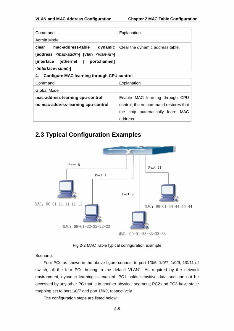
2.3 Typical Configuration Examples
Fig 2-2 MAC Table typical configuration example
Scenario:
Four PCs as shown in the above figure connect to port 1/0/5, 1/0/7, 1/0/9, 1/0/11 of
switch, all the four PCs belong to the default VLAN1. As required by the network
environment, dynamic learning is enabled. PC1 holds sensitive data and can not be
accessed by any other PC that is in another physical segment; PC2 and PC3 have static
mapping set to port 1/0/7 and port 1/0/9, respectively.
The configuration steps are listed below:
VLAN and MAC Address Configuration Chapter 2 MAC Table Configuration
2-6
1. Set the MAC address 00-01-11-11-11-11 of PC1 as a filter address.
Switch(config)#mac-address-table static 00-01-11-11-11-11 discard vlan 1.
2.Set the static mapping relationship for PC2 and PC3 to port 1/0/7 and port 1/0/9,
respectively.
Switch(config)#mac-address-table static address 00-01-22-22-22-22 vlan 1 interface
ethernet 1/0/7
Switch(config)#mac-address-table static address 00-01-33-33-33-33 vlan 1 interface
ethernet 1/0/9
2.4 MAC Table Troubleshooting
Using the show mac-address-table command, a port is found to be failed to learn the
MAC of a device connected to it. Possible reasons:
The connected cable is broken.
Spanning Tree is enabled and the port is in “discarding” status; or the device is
just connected to the port and Spanning Tree is still under calculation, wait until
the Spanning Tree calculation finishes, and the port will learn the MAC address.
If not the problems mentioned above, please check for the switch portand
contact technical support for solution.
2.5 MAC Address Function Extension
2.5.1 MAC Address Binding
2.5.1.1 Introduction to MAC Address Binding
Most switches support MAC address learning, each port can dynamically learn
several MAC addresses, so that forwarding data streams between known MAC addresses
within the ports can be achieved. If a MAC address is aged, the packet destined for that
entry will be broadcasted. In other words, a MAC address learned in a port will be used for
forwarding in that port, if the connection is changed to another port, the switch will learn
the MAC address again to forward data in the new port.
However, in some cases, security or management policy may require MAC
addresses to be bound with the ports, only data stream from the binding MAC are allowed
to be forwarded in the ports. That is to say, after a MAC address is bound to a port, only
the data stream destined for that MAC address can flow in from the binding port, data
stream destined for the other MAC addresses that not bound to the port will not be
VLAN and MAC Address Configuration Chapter 2 MAC Table Configuration
2-7
allowed to pass through the port.
2.5.1.2 MAC Address Binding Configuration Task List
1. Enable MAC address binding function for the ports
2. Lock the MAC addresses for a port
3. MAC address binding property configuration
4. mac-notification trap configuration
1. Enable MAC address binding function for the ports
Command Explanation
Port Mode
switchport port-security no switchport port-security
Enable MAC address binding function for
the port and lock the port. When a port is
locked, the MAC address learning
function for the port will be disabled: the
“no switchport port-security”
command disables the MAC address
binding function for the port, and restores
the MAC address learning function for
the port.
2. Lock the MAC addresses for a port
Command Explanation
Port Mode
switchport port-security lock no switchport port-security lock
Lock the port, then MAC addresses
learned will be disabled. The “no switchport port-security lock”
command restores the function.
switchport port-security convert Convert dynamic secure MAC addresses
learned by the port to static secure MAC
addresses.
switchport port-security timeout <value>
no switchport port-security timeout
Enable port locking timer function; the
“no switchport port-security timeout”
restores the default setting.
switchport port-security mac-address <mac-address> no switchport port-security mac-address <mac-address>
Add static secure MAC address; the
“no switchport port-security mac-address” command deletes static
secure MAC address.
VLAN and MAC Address Configuration Chapter 2 MAC Table Configuration
2-8
Admin Mode
clear port-security dynamic [address <mac-addr> | interface <interface-id>]
Clear dynamic MAC addresses learned
by the specified port.
3. MAC address binding property configuration
Command Explanation
Port Mode
switchport port-security maximum <value> no switchport port-security maximum <value>
Set the maximum number of secure
MAC addresses for a port; the “no switchport port-security maximum”
command restores the default value.
switchport port-security violation {protect | shutdown} [recovery <30-3600>] no switchport port-security violation
Set the violation mode for the port; the
“no switchport port-security violation”
command restores the default setting.
4. mac-notification trap configuration
Command Explanation
Global Mode
mac-address-table periodic-monitor-time <5-86400>
Set the MAC monitor interval to count the
added and deleted MAC in time, and
send out them with trap message.
2.5.1.3 Binding MAC Address Binding Troubleshooting
Enabling MAC address binding for ports may fail in some occasions. Here are some
possible causes and solutions:
If MAC address binding cannot be enabled for a port, make sure the port is not
enabling port aggregation and is not configured as a Trunk port. MAC address binding
is exclusive to such configurations. If MAC address binding is to be enabled, the
functions mentioned above must be disabled first.
If a secure address is set as static address and deleted, that secure address will be
unusable even though it exists. For this reason, it is recommended to avoid static
address for ports enabling MAC address.
2.6 MAC Notification Configuration
2.6.1 Introduction to MAC Notification
MAC Notification function depends on the notification. Add or remove the MAC
VLAN and MAC Address Configuration Chapter 2 MAC Table Configuration
2-9
address, namely, when the device is added or removed, it will notify administrator about
the changing by the trap function of snmp.
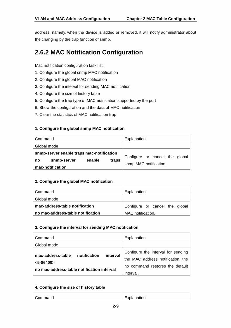
2.6.2 MAC Notification Configuration
Mac notification configuration task list:
1. Configure the global snmp MAC notification
2. Configure the global MAC notification
3. Configure the interval for sending MAC notification
4. Configure the size of history table
5. Configure the trap type of MAC notification supported by the port
6. Show the configuration and the data of MAC notification
7. Clear the statistics of MAC notification trap
1. Configure the global snmp MAC notification
2. Configure the global MAC notification
3. Configure the interval for sending MAC notification
4. Configure the size of history table
Command Explanation
Global mode
snmp-server enable traps mac-notification no snmp-server enable traps mac-notification
Configure or cancel the global
snmp MAC notification.
Command Explanation
Global mode
mac-address-table notification no mac-address-table notification
Configure or cancel the global
MAC notification.
Command Explanation
Global mode
mac-address-table notification interval <5-86400> no mac-address-table notification interval
Configure the interval for sending
the MAC address notification, the
no command restores the default
interval.
Command Explanation
VLAN and MAC Address Configuration Chapter 2 MAC Table Configuration
2-10
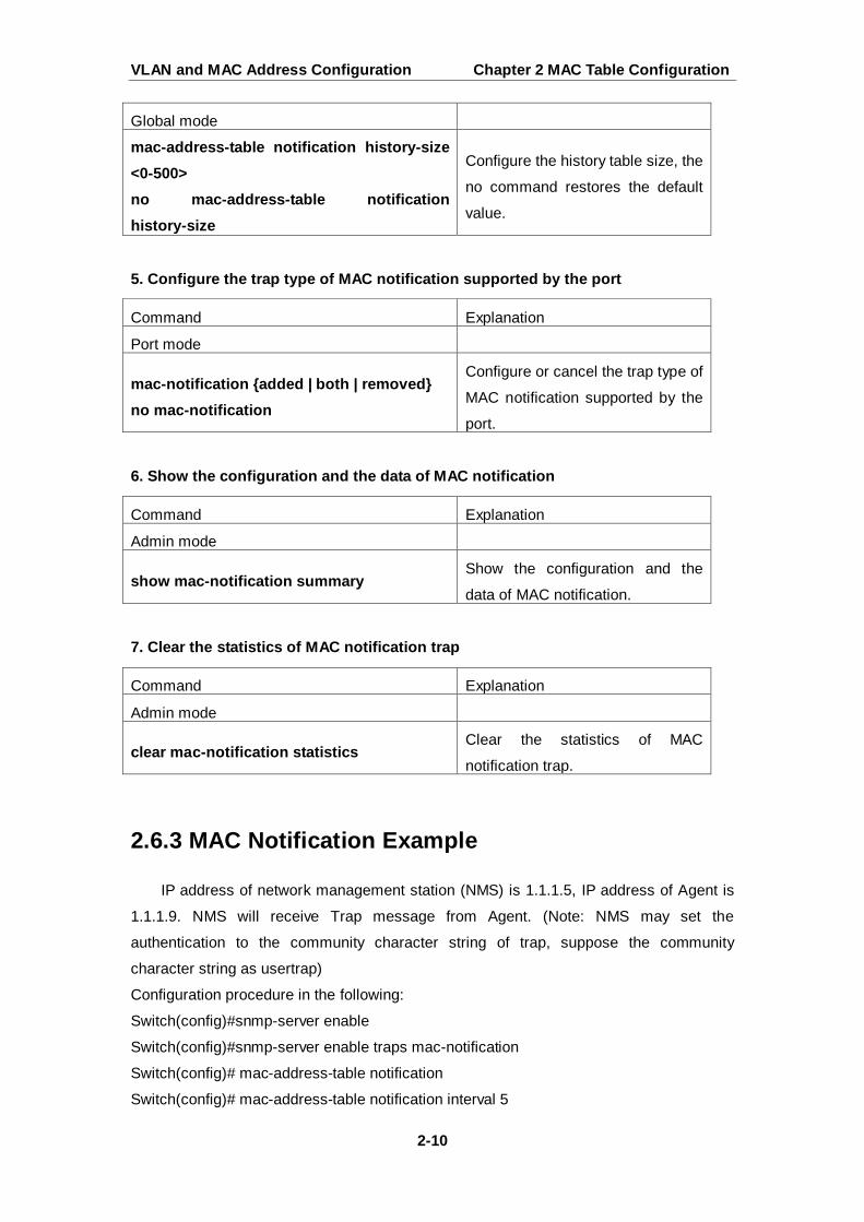
5. Configure the trap type of MAC notification supported by the port
6. Show the configuration and the data of MAC notification
7. Clear the statistics of MAC notification trap
2.6.3 MAC Notification Example
IP address of network management station (NMS) is 1.1.1.5, IP address of Agent is
1.1.1.9. NMS will receive Trap message from Agent. (Note: NMS may set the
authentication to the community character string of trap, suppose the community
character string as usertrap)
Configuration procedure in the following:
Switch(config)#snmp-server enable
Switch(config)#snmp-server enable traps mac-notification
Switch(config)# mac-address-table notification
Switch(config)# mac-address-table notification interval 5
Global mode
mac-address-table notification history-size <0-500> no mac-address-table notification history-size
Configure the history table size, the
no command restores the default
value.
Command Explanation
Port mode
mac-notification {added | both | removed} no mac-notification
Configure or cancel the trap type of
MAC notification supported by the
port.
Command Explanation
Admin mode
show mac-notification summary Show the configuration and the
data of MAC notification.
Command Explanation
Admin mode
clear mac-notification statistics Clear the statistics of MAC
notification trap.

VLAN and MAC Address Configuration Chapter 2 MAC Table Configuration
2-11
Switch(config)# mac-address-table notification history-size 100
Switch(Config-If-Ethernet1/0/4)# mac-notification both
2.6.4 MAC Notification Troubleshooting
Check whether trap message is sent successfully by show command and debug
command of snmp.


