02 RA45312EN05GLA0 Flexi WCDMA BTS Module Installation
62
1 © Nokia Siemens Networks RA45312EN05GLA0 Flexi WCDMA BTS Module Installation RU10
-
Upload
ahmed-bouri -
Category
Documents
-
view
229 -
download
10
Transcript of 02 RA45312EN05GLA0 Flexi WCDMA BTS Module Installation

1 © Nokia Siemens Networks RA45312EN05GLA0
Flexi WCDMA BTS Module Installation RU10

2 © Nokia Siemens Networks RA45312EN05GLA0
Nokia Siemens Networks Academy
Legal notice
Intellectual Property RightsAll copyrights and intellectual property rights for Nokia Siemens Networks training documentation, product documentation and slide presentation material, all of which are forthwith known as NSN training material, are the exclusive property of NSN. NSN owns the rights to copying, modification, translation, adaptation or derivatives including any improvements or developments. NSN has the sole right to copy, distribute, amend, modify, develop, license, sublicense, sell, transfer and assign the NSN training material. Individuals can use the NSN training material for their own personal self-development only, those same individuals cannot subsequently pass on that same Intellectual Property to others without the prior written agreement of NSN. The NSN training material cannot be used outside of an agreed NSN training session for development of groups without the prior written agreement of NSN .
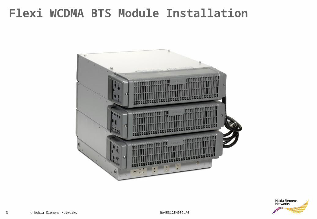
3 © Nokia Siemens Networks RA45312EN05GLA0
Flexi WCDMA BTS Module Installation
4 © Nokia Siemens Networks RA45312EN05GLA0
Flexi WCDMA BTS Module Installation
After completing this module, the participant will be able to:
Practical:
Examine for correctly installed NSN Flexi WCDMA BTS modules

5 © Nokia Siemens Networks RA45312EN05GLA0
Flexi WCDMA BTS Module Installation
AC/DC Power Module
System Module
RF Modules 1-3
6 © Nokia Siemens Networks RA45312EN05GLA0
Flexi WCDMA BTS Module Installation
After completing this module, the participant will be able to:
Theory:
Describe installation options for NSN Flexi WCDMA BTS
Practical:
Install NSN Flexi WCDMA BTS modules
7 © Nokia Siemens Networks RA45312EN05GLA0
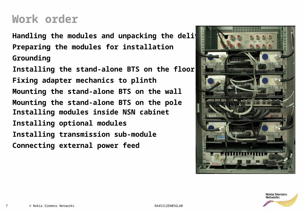
Handling the modules and unpacking the delivery
Preparing the modules for installation
Grounding
Installing the stand-alone BTS on the floor
Fixing adapter mechanics to plinth
Mounting the stand-alone BTS on the wall
Mounting the stand-alone BTS on the pole Installing modules inside NSN cabinet
Installing optional modules
Installing transmission sub-module
Connecting external power feed
Work order

8 © Nokia Siemens Networks RA45312EN05GLA0
Handling the modules and unpacking the delivery
When handling the modules, always use the antistatic wrist strap as shown in the figure below. The cabinet must be grounded, otherwise the antistatic wrist strap will not work. Refer to Grounding the BTS section.
ESD ANTI-STATIC WRIST STRAPS SHOULD BE WORN WHEN HANDLING ANY UNIT WHICH DISPLAYS THE ESD
LOGO
ESD ANTI-STATIC WRIST STRAPS SHOULD BE WORN WHEN HANDLING ANY UNIT WHICH DISPLAYS THE ESD
LOGO

9 © Nokia Siemens Networks RA45312EN05GLA0
Unpack and check the delivery System Module
Delivery contains module, cable entries, ESD wrist strap, cable clamps, screws.

10 © Nokia Siemens Networks RA45312EN05GLA0
Unpack and check the delivery RF Module
Delivery contains module with cabling, cable entries, optical cable assembly, Power cable assembly, 2 optical transceivers (SFP), screws.
11 © Nokia Siemens Networks RA45312EN05GLA0
Flexi WCDMA BTS Standalone Installation

12 © Nokia Siemens Networks RA45312EN05GLA0
Preparing the modules for a stand-alone installation 1/2
• Module rear cover must be attached first to protect moving parts
• Safety catch should be installed for wall and pole installation

13 © Nokia Siemens Networks RA45312EN05GLA0
Preparing the modules for a stand-alone installation 2/2

14 © Nokia Siemens Networks RA45312EN05GLA0
There are two options as to how to lift a stand-alone BTS:
• A stand-alone BTS can be lifted stacked (max. two modules per plinth) and cabled. When lifting a stacked BTS, the lifting points on the plinth must be used.
• The plinth can be lifted and mounted first and then each module lifted separately. When lifting a single module, a lifting bag must be used.
Attach the hoisting belt or rope so that the angle between the belt or rope and the plinth is minimum 60°. The distance between the plinth and the belt or rope is minimum 400 mm.
Lifting the stand-alone BTS
The equipment is heavy. Take care when lifting it.

15 © Nokia Siemens Networks RA45312EN05GLA0
Grounding principle of the stand-alone BTS
16 © Nokia Siemens Networks RA45312EN05GLA0
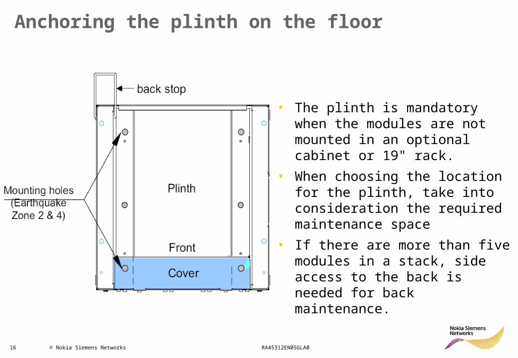
Anchoring the plinth on the floor
• The plinth is mandatory when the modules are not mounted in an optional cabinet or 19" rack.
• When choosing the location for the plinth, take into consideration the required maintenance space
• If there are more than five modules in a stack, side access to the back is needed for back maintenance.
17 © Nokia Siemens Networks RA45312EN05GLA0
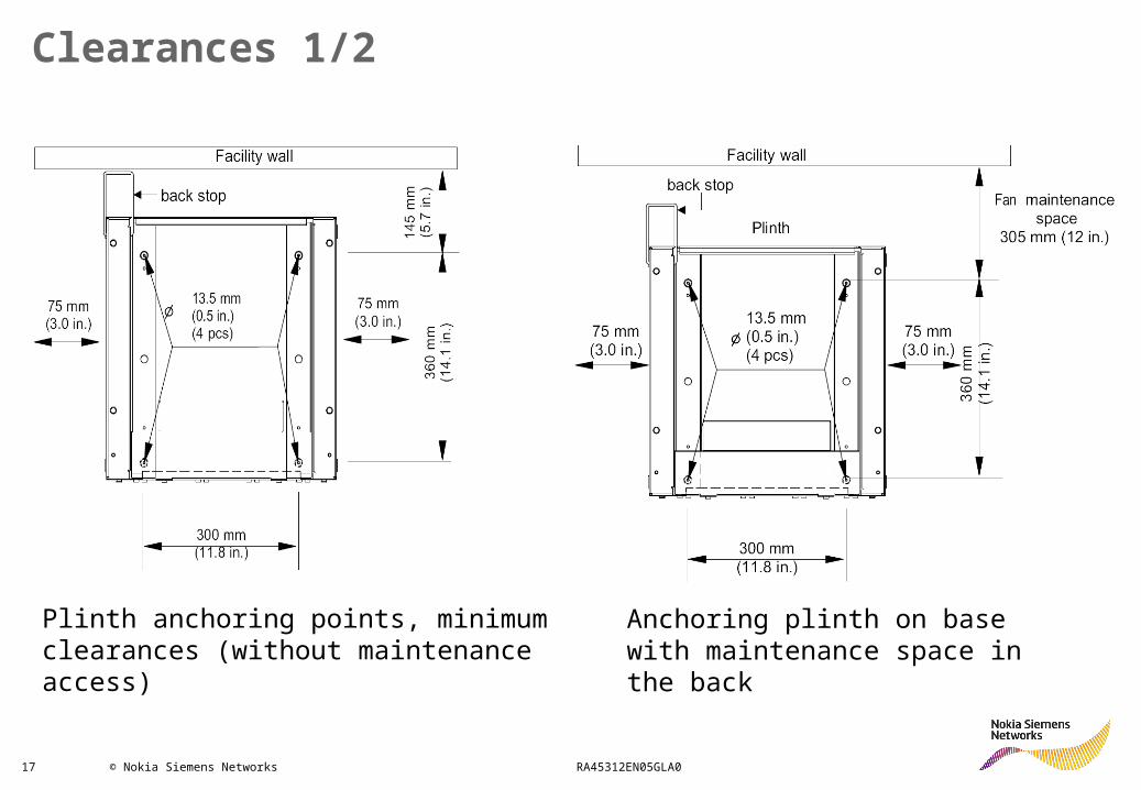
Clearances 1/2
Plinth anchoring points, minimum clearances (without maintenance access)
Anchoring plinth on base with maintenance space in the back
18 © Nokia Siemens Networks RA45312EN05GLA0
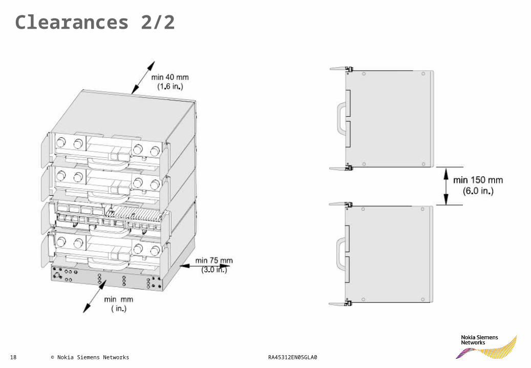
Clearances 2/2

19 © Nokia Siemens Networks RA45312EN05GLA0
Installing modules on the floor
• The stand-alone BTS (without a cabinet) can be installed on the floor in a stack of up to nine modules (maximum height 27U).
• To meet the earthquake requirement for Zone 4, no more than five modules (maximum height 15U) can be installed in one stack. More than six modules in a stack meets the vibrational requirements for earthquake Zone 2.
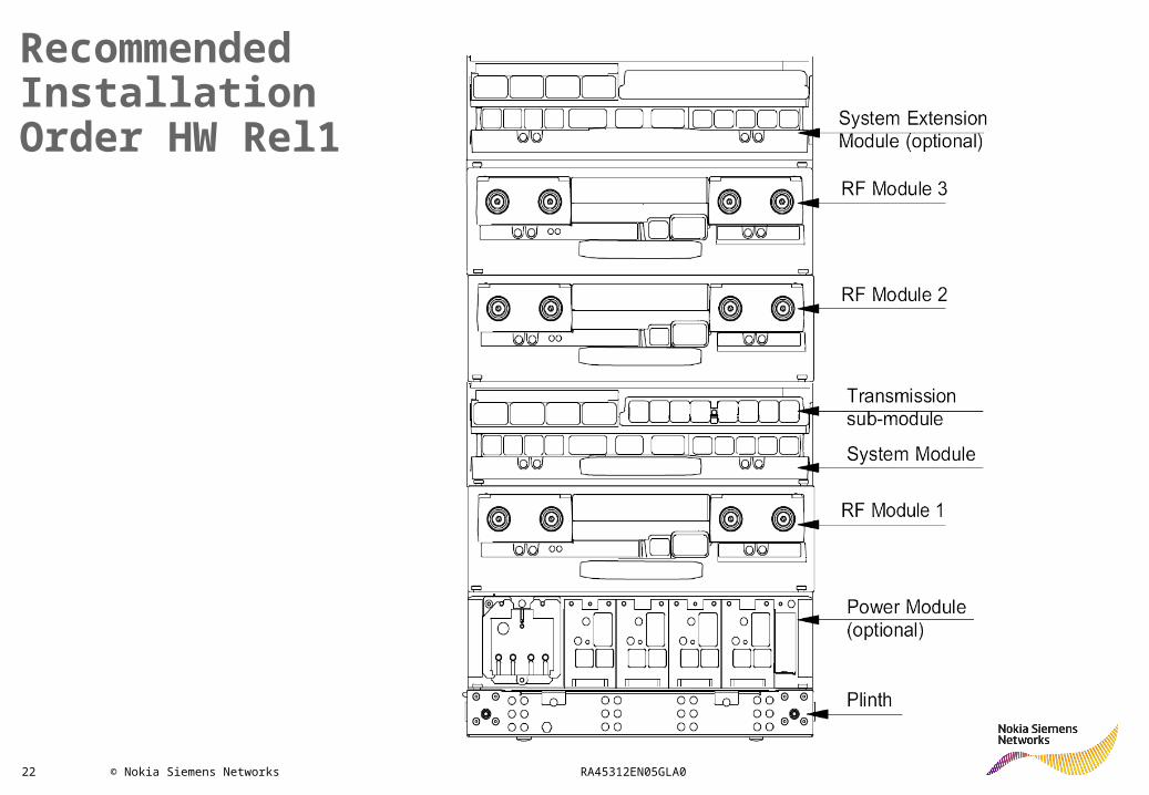
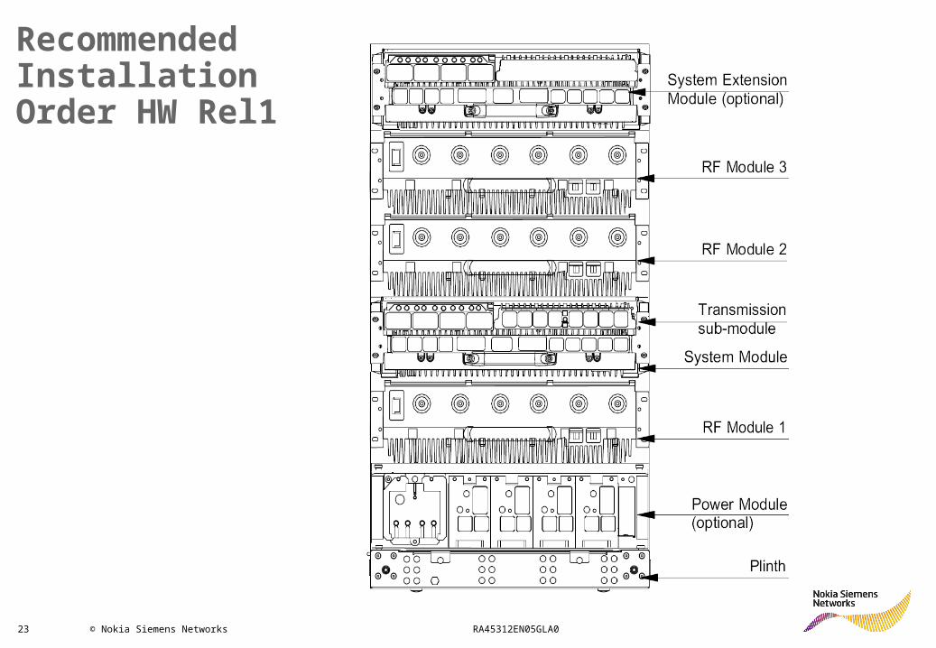
• If Flexi Power Module (FPMA) is used, its recommended position is at the bottom of the module stack

20 © Nokia Siemens Networks RA45312EN05GLA0
Installing modules on the floor
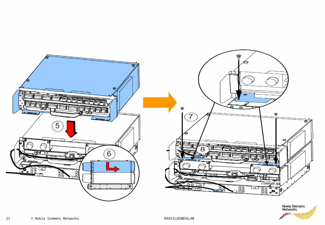
21 © Nokia Siemens Networks RA45312EN05GLA0
22 © Nokia Siemens Networks RA45312EN05GLA0
Recommended Installation Order HW Rel1
23 © Nokia Siemens Networks RA45312EN05GLA0
Recommended Installation Order HW Rel1

24 © Nokia Siemens Networks RA45312EN05GLA0
Flexi WCDMA BTS Wall and Pole Installation
25 © Nokia Siemens Networks RA45312EN05GLA0
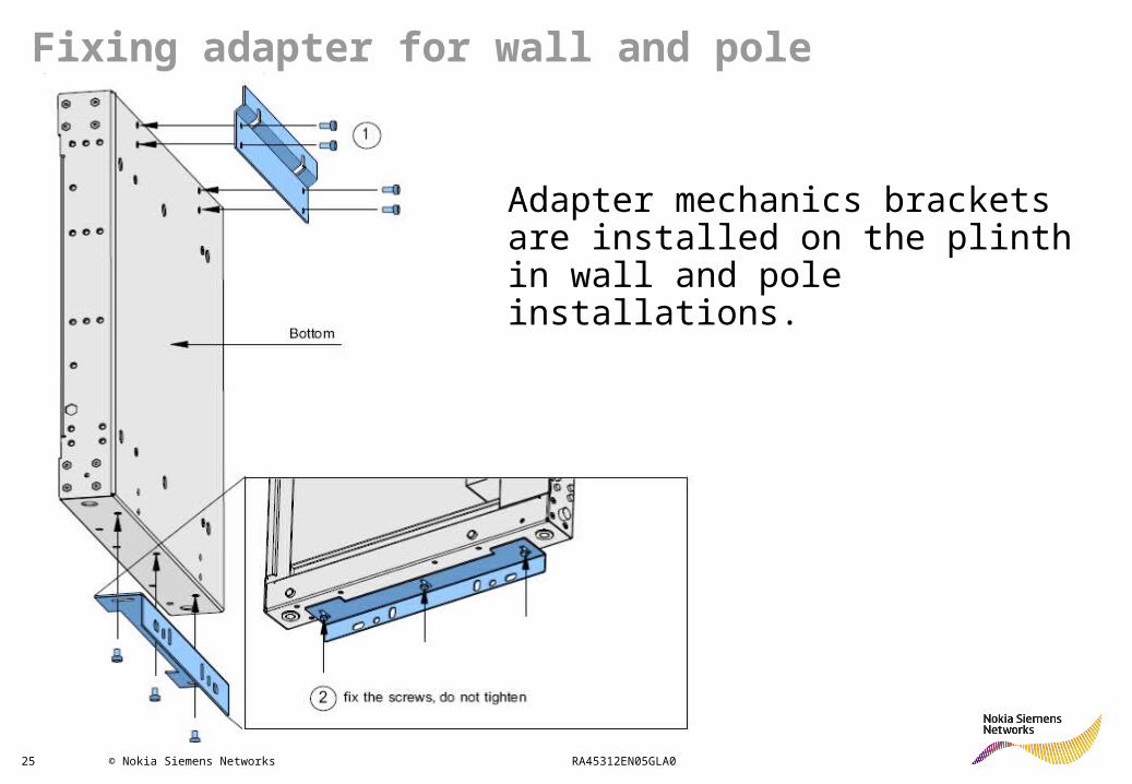
Fixing adapter for wall and pole installations
Adapter mechanics brackets are installed on the plinth in wall and pole installations.
26 © Nokia Siemens Networks RA45312EN05GLA0
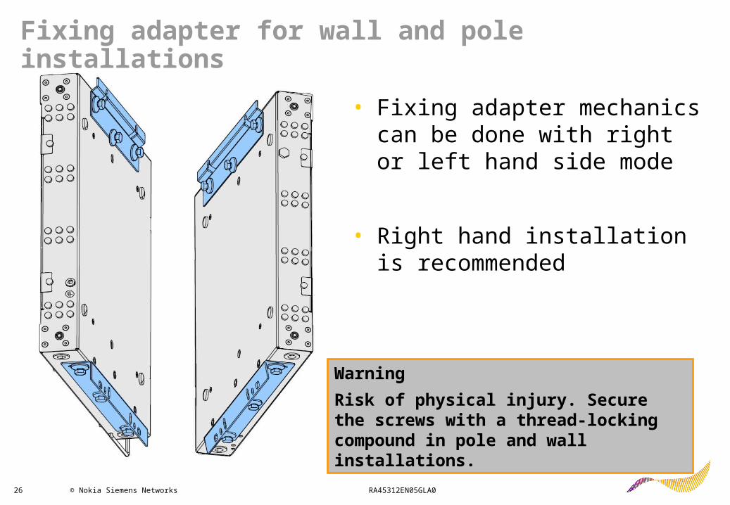
Fixing adapter for wall and pole installations
• Fixing adapter mechanics can be done with right or left hand side mode
• Right hand installation is recommended
Warning
Risk of physical injury. Secure the screws with a thread-locking compound in pole and wall installations.
27 © Nokia Siemens Networks RA45312EN05GLA0
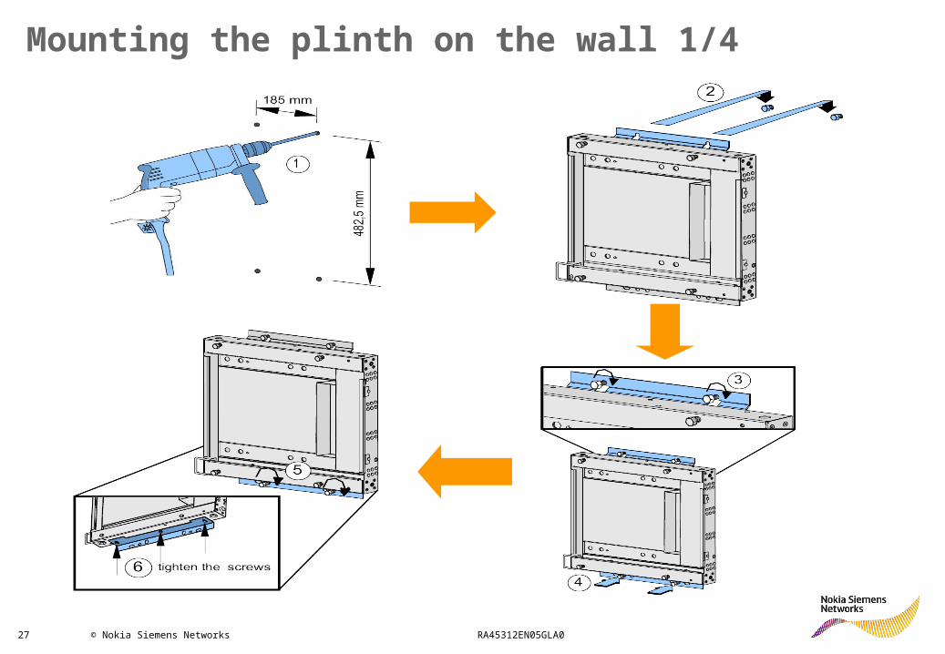
Mounting the plinth on the wall 1/4

28 © Nokia Siemens Networks RA45312EN05GLA0
Mounting the plinth on the wall 2/4

29 © Nokia Siemens Networks RA45312EN05GLA0
Mounting the modules on the wall 3/4

30 © Nokia Siemens Networks RA45312EN05GLA0
Mounting the modules on the wall 4/4
The stand-alone BTS can be installed on a wall. The maximum number of modules per plinth is two.
If Flexi Power Module (FPMA) is used, it should be installed on the same plinth as the System Module
Excess torsion damages the casings. In wall and pole installation, do not install more than two modules per plinth

31 © Nokia Siemens Networks RA45312EN05GLA0
Caution
Incorrect installation may lead to damage to the modules.
The modulesmust be installed with the front panels facing left or right.
Do not installthe modules with the front panels facing up or down.

32 © Nokia Siemens Networks RA45312EN05GLA0
Mounting the plinth on a pole with VMPB
Pole mounting brackets bolt lengths, hole numbers and torque values
Pole mounting bracket hole numbering
There are three different lengths of bolts available and four places for the
bolts in the pole mounting brackets. When attaching the brackets to the
pole, use the shortest possible bolts and the holes whose distance is the
closest to the pole diameter. See the following table and figure for more
details.
Pole Diameter Bolt length Hole Number* Torque value
60 - 90 mm 120 mm 1 29 Nm
95 - 125 mm 120 mm 2 29 Nm
126 - 165 mm 200 mm 1 29 Nm
166 - 210 mm 200 mm 2 29 Nm
211 - 255 mm 300 mm 3 29 Nm
256 - 300 mm 300 mm 4 29 Nm
*Hole numbering is presented in the following figure
33 © Nokia Siemens Networks RA45312EN05GLA0
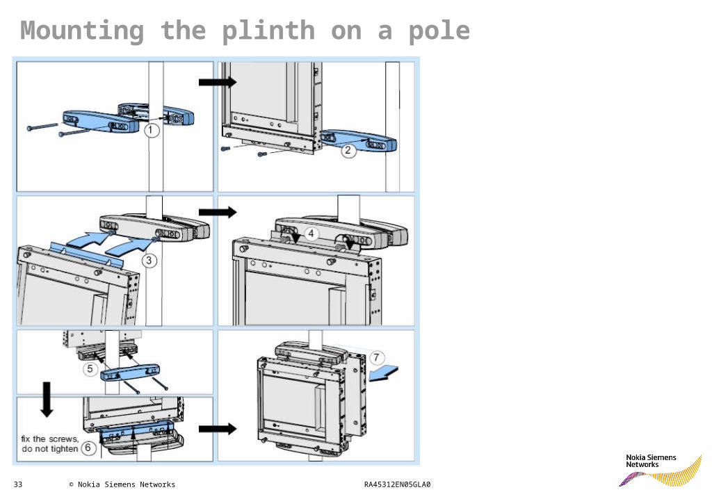
Mounting the plinth on a pole
34 © Nokia Siemens Networks RA45312EN05GLA0
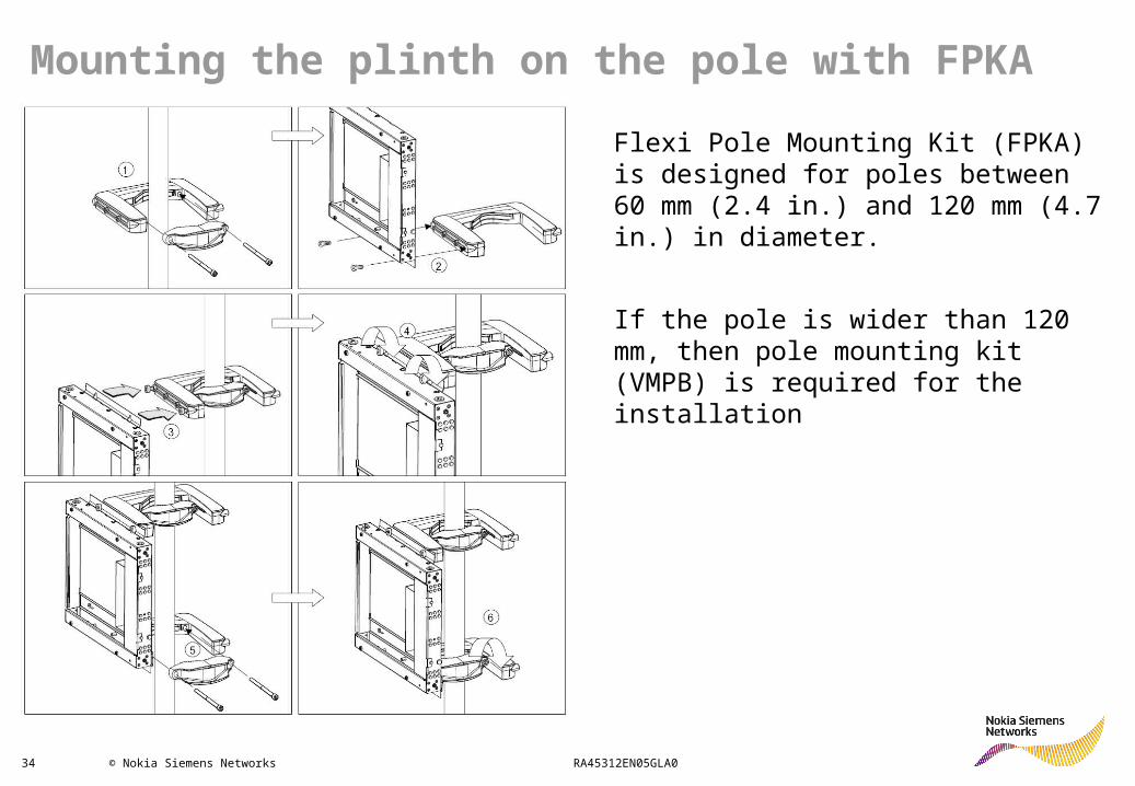
Mounting the plinth on the pole with FPKA
Flexi Pole Mounting Kit (FPKA) is designed for poles between 60 mm (2.4 in.) and 120 mm (4.7 in.) in diameter.
If the pole is wider than 120 mm, then pole mounting kit (VMPB) is required for the installation
35 © Nokia Siemens Networks RA45312EN05GLA0
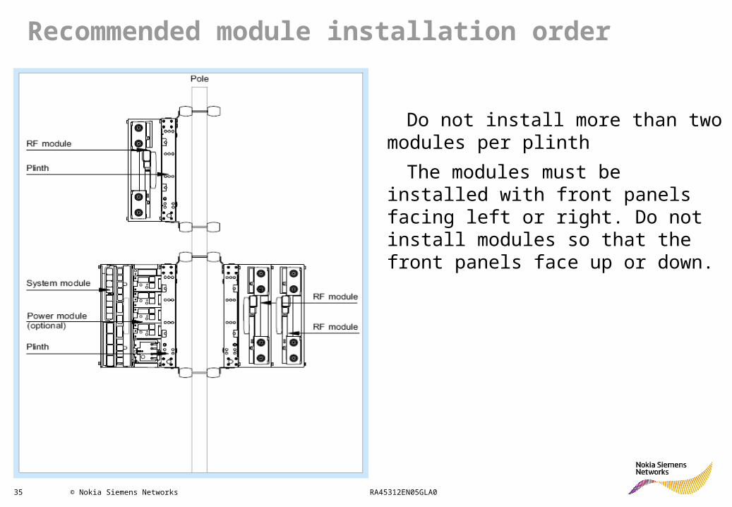
Recommended module installation order
Do not install more than two modules per plinth
The modules must be installed with front panels facing left or right. Do not install modules so that the front panels face up or down.
36 © Nokia Siemens Networks RA45312EN05GLA0
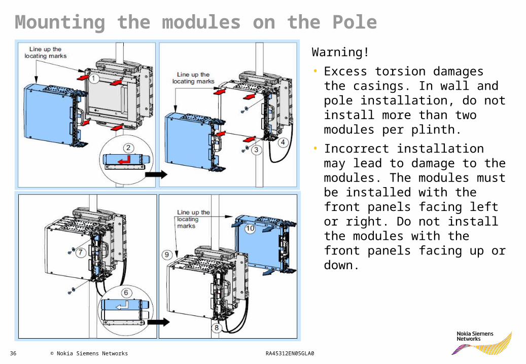
Mounting the modules on the Pole
Warning!
• Excess torsion damages the casings. In wall and pole installation, do not install more than two modules per plinth.
• Incorrect installation may lead to damage to the modules. The modules must be installed with the front panels facing left or right. Do not install the modules with the front panels facing up or down.
37 © Nokia Siemens Networks RA45312EN05GLA0
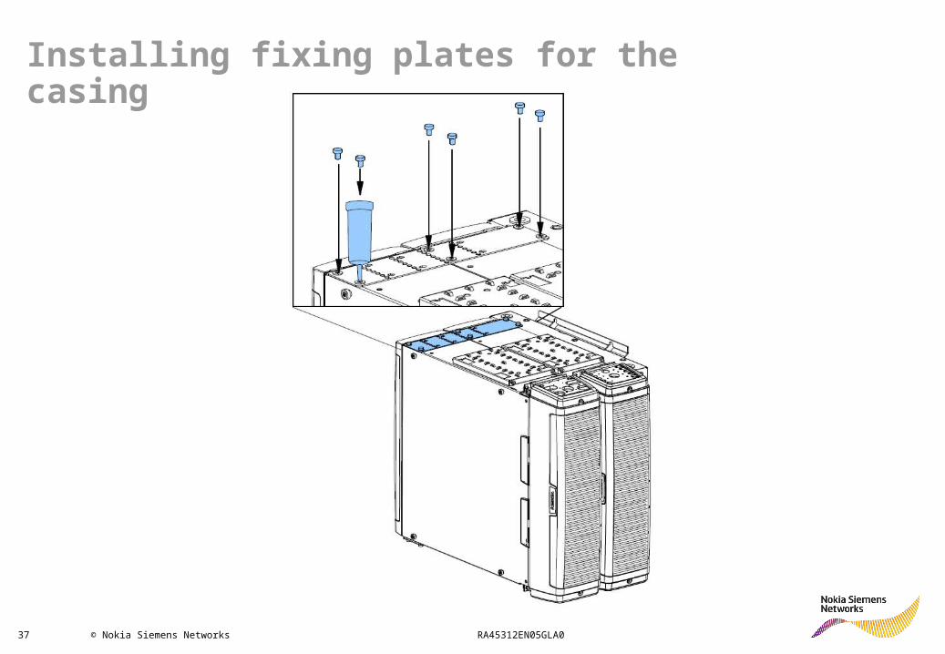
Installing fixing plates for the casing
38 © Nokia Siemens Networks RA45312EN05GLA0
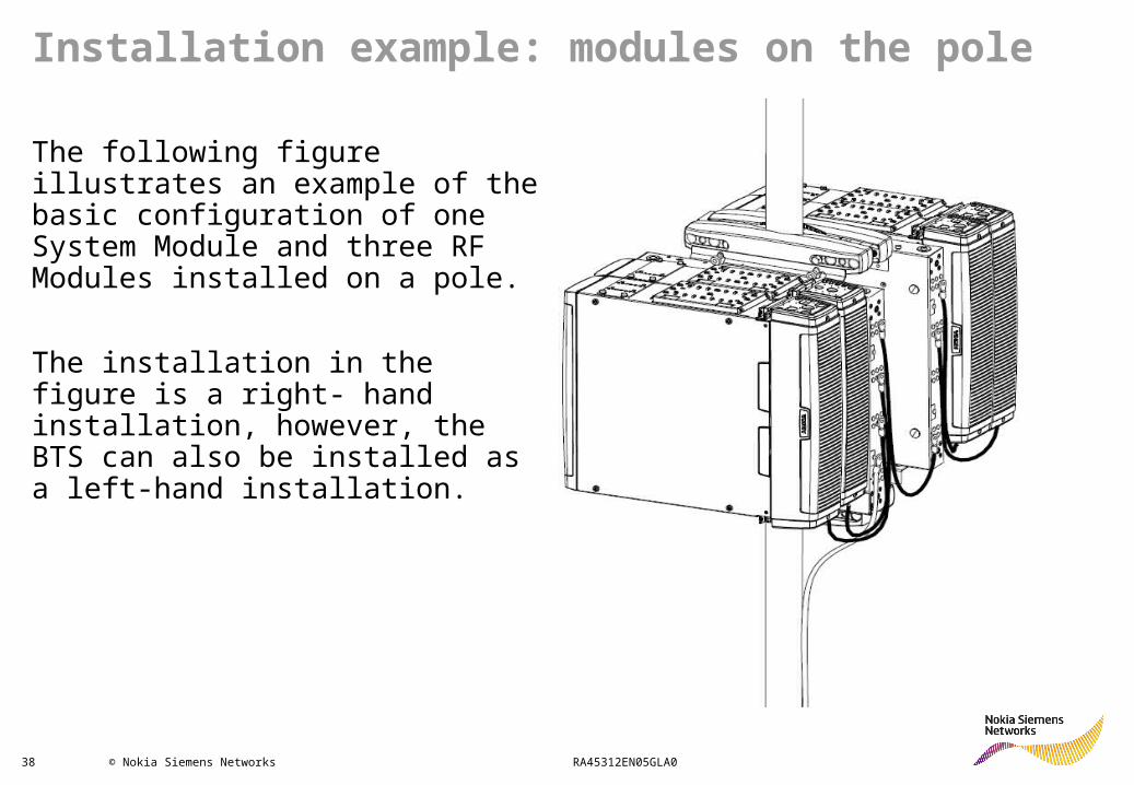
Installation example: modules on the pole
The following figure illustrates an example of the basic configuration of one System Module and three RF Modules installed on a pole.
The installation in the figure is a right- hand installation, however, the BTS can also be installed as a left-hand installation.

39 © Nokia Siemens Networks RA45312EN05GLA0
Transmission sub-module installation
40 © Nokia Siemens Networks RA45312EN05GLA0
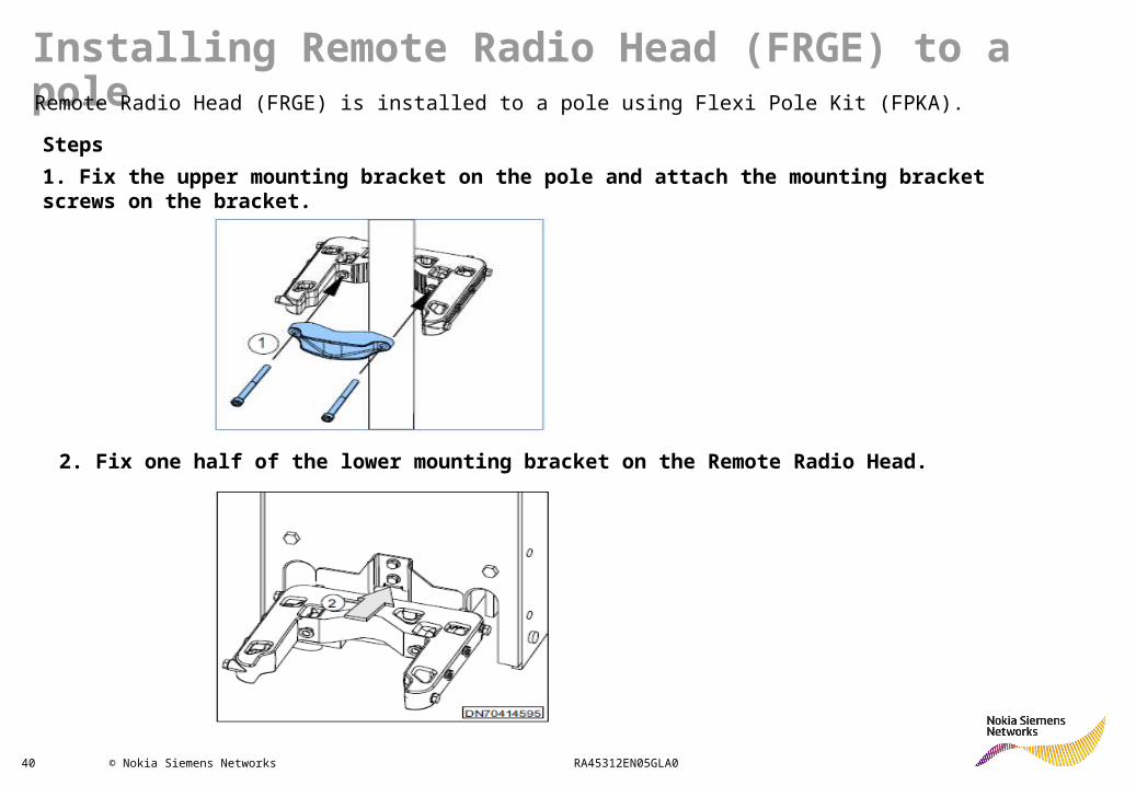
Installing Remote Radio Head (FRGE) to a poleRemote Radio Head (FRGE) is installed to a pole using Flexi Pole Kit (FPKA).
Steps
1. Fix the upper mounting bracket on the pole and attach the mounting bracket screws on the bracket.
2. Fix one half of the lower mounting bracket on the Remote Radio Head.
41 © Nokia Siemens Networks RA45312EN05GLA0
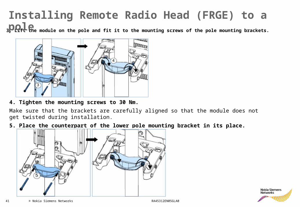
3. Lift the module on the pole and fit it to the mounting screws of the pole mounting brackets.
4. Tighten the mounting screws to 30 Nm.
Make sure that the brackets are carefully aligned so that the module does not get twisted during installation.
5. Place the counterpart of the lower pole mounting bracket in its place.
Installing Remote Radio Head (FRGE) to a pole
42 © Nokia Siemens Networks RA45312EN05GLA0
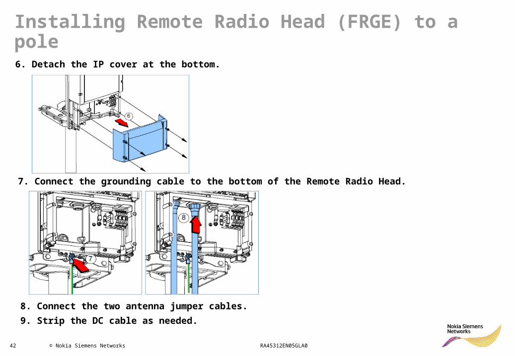
6. Detach the IP cover at the bottom.
7. Connect the grounding cable to the bottom of the Remote Radio Head.
8. Connect the two antenna jumper cables.
9. Strip the DC cable as needed.
Installing Remote Radio Head (FRGE) to a pole

43 © Nokia Siemens Networks RA45312EN05GLA0
10. Connect the DC cable.Connect the black wire to the terminal marked with a plus sign (+) and the blue wire to the terminal marked with a minus sign (-).
11. Install the SFP
Installing Remote Radio Head (FRGE) to a pole
44 © Nokia Siemens Networks RA45312EN05GLA0
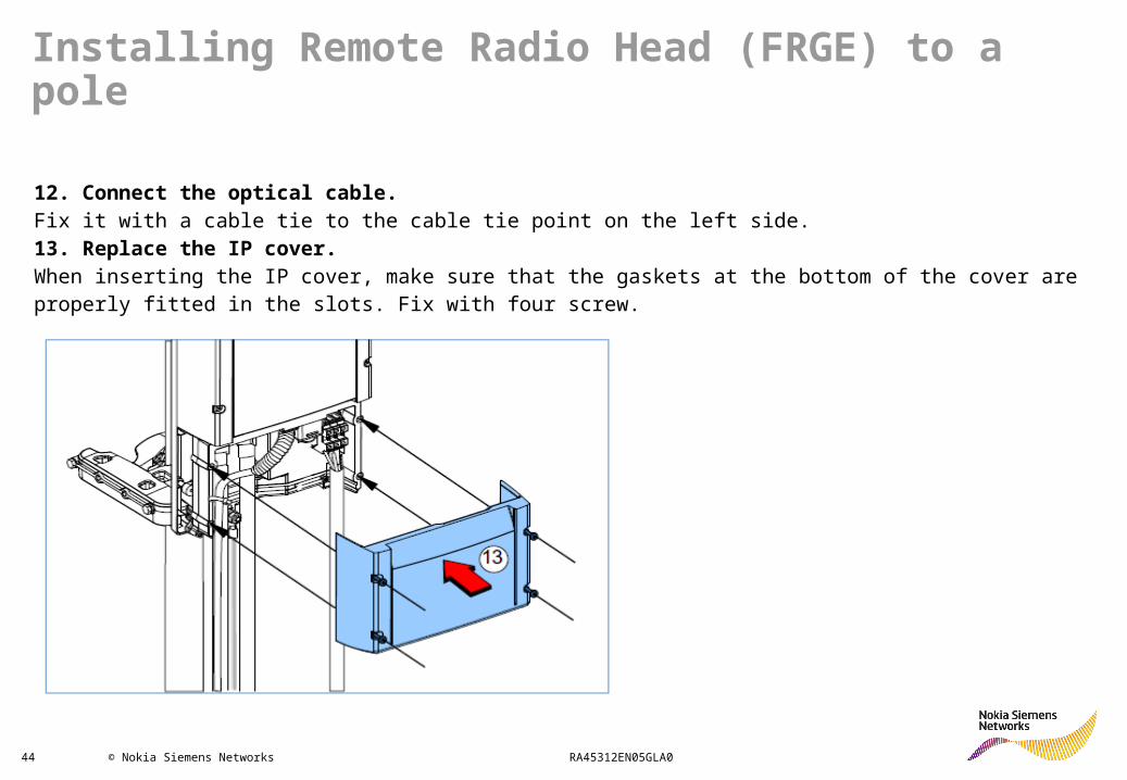
12. Connect the optical cable.Fix it with a cable tie to the cable tie point on the left side.13. Replace the IP cover.When inserting the IP cover, make sure that the gaskets at the bottom of the cover are properly fitted in the slots. Fix with four screw.
Installing Remote Radio Head (FRGE) to a pole

45 © Nokia Siemens Networks RA45312EN05GLA0
Installing Remote Radio Head (FRGE) to a wall
Steps
1. Mark the mounting hole locations on the wall and drill the holes for the screws (or any other fixing method).
2. Fix the upper mounting screws to the wall.
3. Lift the Remote Radio Head on the wall and fit it to the mounting
screws.
Tighten the screws.

46 © Nokia Siemens Networks RA45312EN05GLA0
4. Insert the lower mounting screws.
5. Tighten the screws.
6. Detach the IP cover at the bottom.
Installing Remote Radio Head (FRGE) to a wall

47 © Nokia Siemens Networks RA45312EN05GLA0
7. Connect the grounding cable to the bottom of the Remote Radio head
8. Connect the two antenna jumper cables.
9. Strip the DC cable as needed.
Installing Remote Radio Head (FRGE) to a wall
48 © Nokia Siemens Networks RA45312EN05GLA0
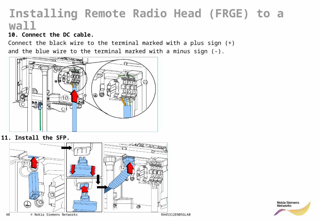
10. Connect the DC cable.
Connect the black wire to the terminal marked with a plus sign (+)
and the blue wire to the terminal marked with a minus sign (-).
11. Install the SFP.
Installing Remote Radio Head (FRGE) to a wall
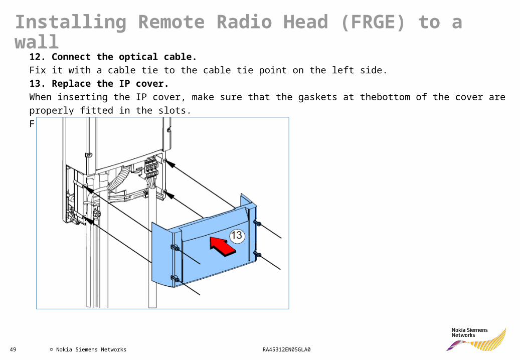
49 © Nokia Siemens Networks RA45312EN05GLA0
12. Connect the optical cable.
Fix it with a cable tie to the cable tie point on the left side.
13. Replace the IP cover.
When inserting the IP cover, make sure that the gaskets at thebottom of the cover are properly fitted in the slots.
Fix with four screw.
Installing Remote Radio Head (FRGE) to a wall
50 © Nokia Siemens Networks RA45312EN05GLA0
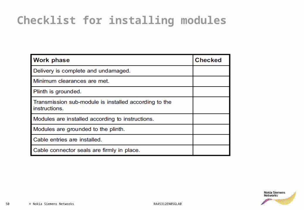
Checklist for installing modules
51 © Nokia Siemens Networks RA45312EN05GLA0
Flexi WCDMA BTS Delivery Package

52 © Nokia Siemens Networks RA45312EN05GLA0
Delivery contents of the System Module
The System Module delivery contains the following items:
• System Module
• 2 x System Module cable entries
• ESD wrist strap
• 2 x cable clamps
• Stress relief plate for the power cable
• 4 x M5 screws for fixing cable entries to the casing
• 4 x K30 screws for the cable clamps
• 2 x M5 screws for fixing the casing to another casing or plinth
• 20 x cable ties
• Flexi WCDMA BTS Quick Guide

53 © Nokia Siemens Networks RA45312EN05GLA0
Contents of the RF Module delivery
The RF Module delivery contains the following items:
• RF Module
• 2 x RF Module cable entries
• Optical cable
• Power cable
• 2 x optical transceivers
• 4 x M5 screws for fixing cable entries to the casing
• 2 x M5 screws for fixing the casing to another casing or plinth
• 10 x cable ties
54 © Nokia Siemens Networks RA45312EN05GLA0
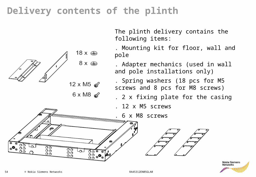
Delivery contents of the plinth
The plinth delivery contains the following items:
. Mounting kit for floor, wall and pole
. Adapter mechanics (used in wall and pole installations only)
. Spring washers (18 pcs for M5 screws and 8 pcs for M8 screws)
. 2 x fixing plate for the casing
. 12 x M5 screws
. 6 x M8 screws
55 © Nokia Siemens Networks RA45312EN05GLA0
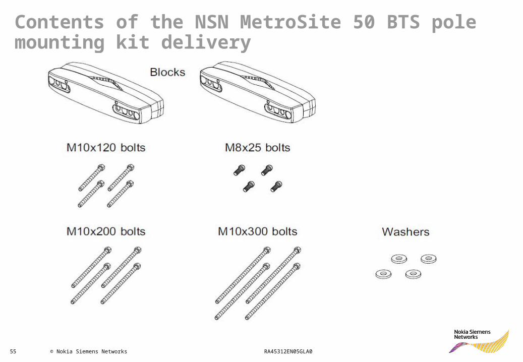
Contents of the NSN MetroSite 50 BTS pole mounting kit delivery
56 © Nokia Siemens Networks RA45312EN05GLA0
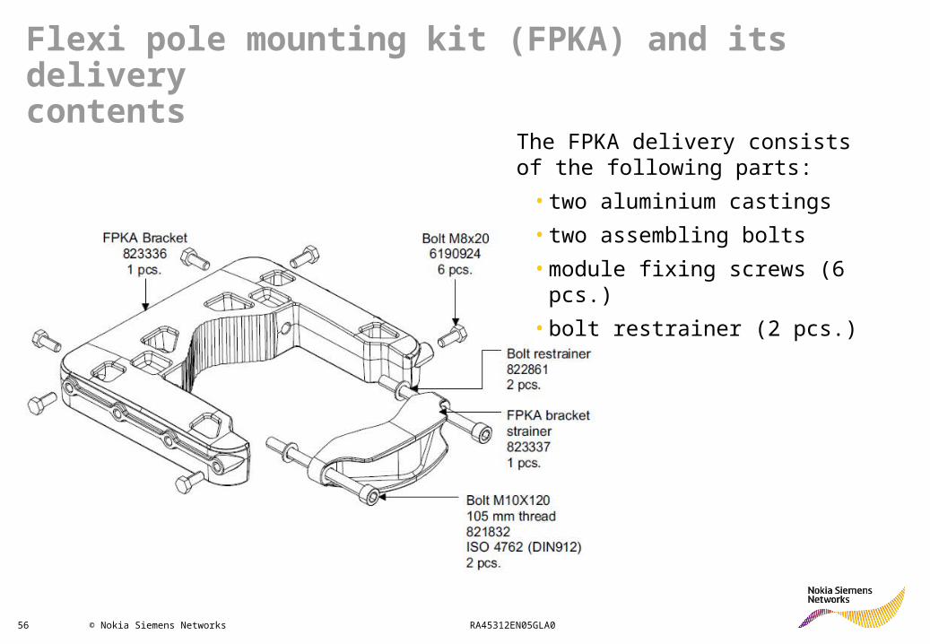
Flexi pole mounting kit (FPKA) and its deliverycontents
The FPKA delivery consists of the following parts:
• two aluminium castings
• two assembling bolts
• module fixing screws (6 pcs.)
• bolt restrainer (2 pcs.)
57 © Nokia Siemens Networks RA45312EN05GLA0
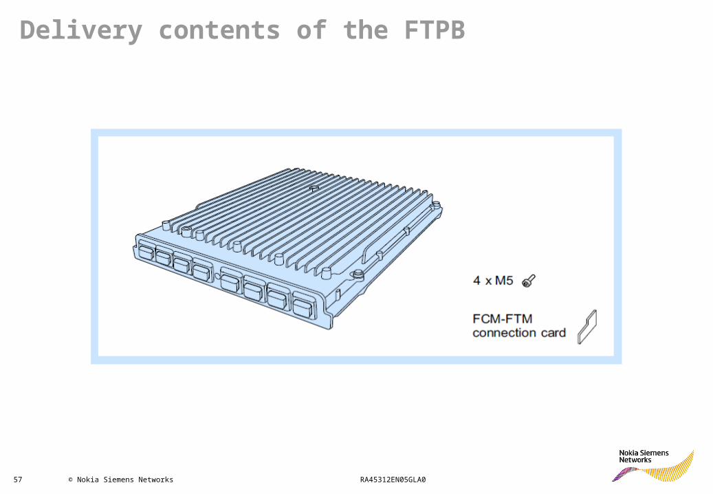
Delivery contents of the FTPB
58 © Nokia Siemens Networks RA45312EN05GLA0
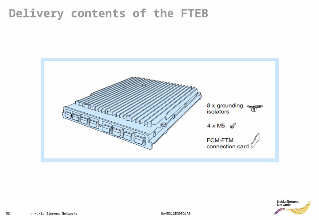
Delivery contents of the FTEB
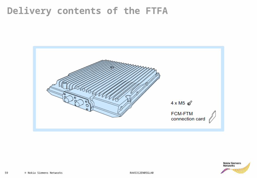
59 © Nokia Siemens Networks RA45312EN05GLA0
Delivery contents of the FTFA

60 © Nokia Siemens Networks RA45312EN05GLA0
Delivery contents of the FTIA
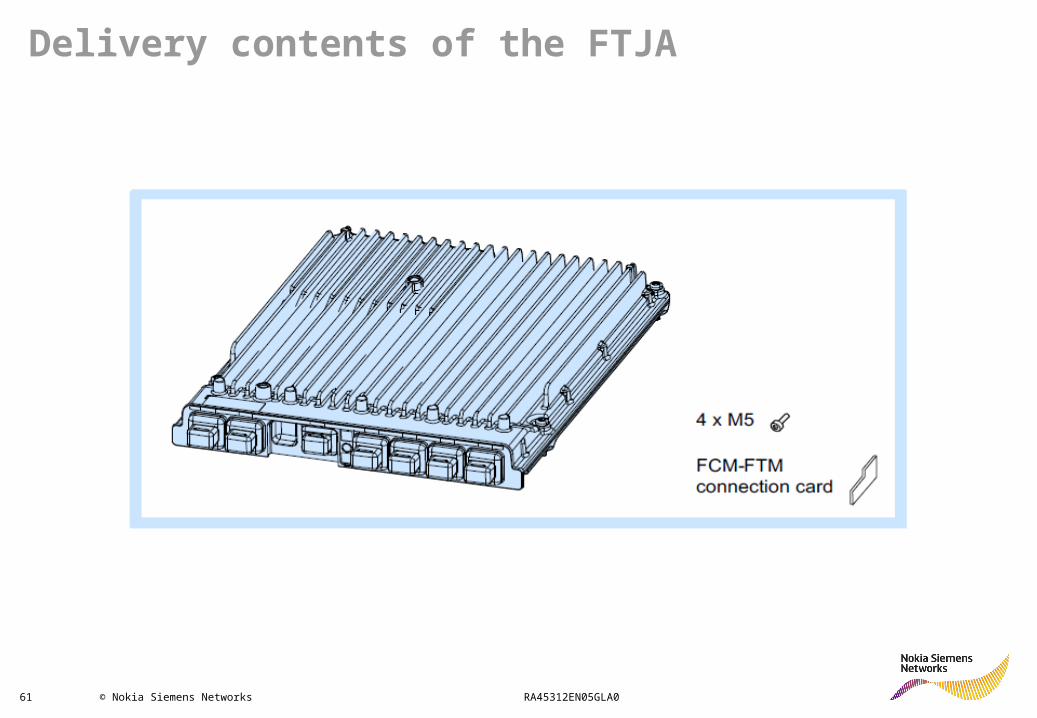
61 © Nokia Siemens Networks RA45312EN05GLA0
Delivery contents of the FTJA

62 © Nokia Siemens Networks RA45312EN05GLA0
Delivery contents of the FTOA