01 prelims 7. - macmillanihe.com · 6.3 Calculation of deflection 142 ... 6.5 Thermal and shrinkage...
27
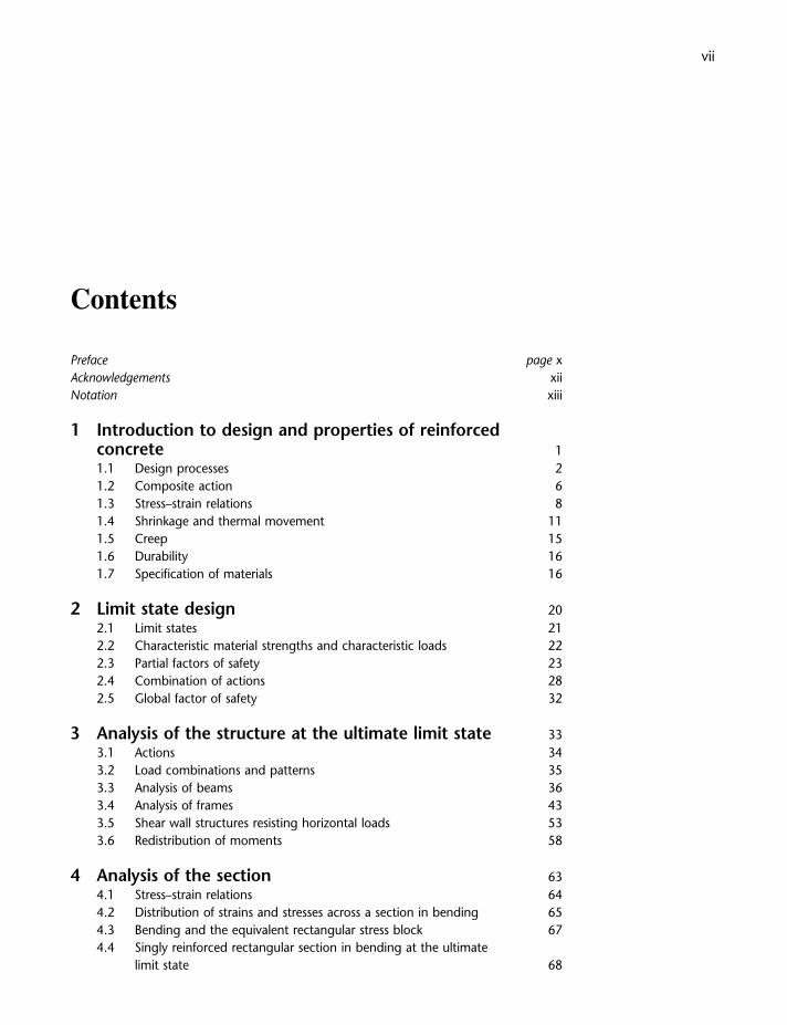
vii Contents Preface page x Acknowledgements xii Notation xiii 1 Introduction to design and properties of reinforced concrete 1 1.1 Design processes 2 1.2 Composite action 6 1.3 Stress–strain relations 8 1.4 Shrinkage and thermal movement 11 1.5 Creep 15 1.6 Durability 16 1.7 Specification of materials 16 2 Limit state design 20 2.1 Limit states 21 2.2 Characteristic material strengths and characteristic loads 22 2.3 Partial factors of safety 23 2.4 Combination of actions 28 2.5 Global factor of safety 32 3 Analysis of the structure at the ultimate limit state 33 3.1 Actions 34 3.2 Load combinations and patterns 35 3.3 Analysis of beams 36 3.4 Analysis of frames 43 3.5 Shear wall structures resisting horizontal loads 53 3.6 Redistribution of moments 58 4 Analysis of the section 63 4.1 Stress–strain relations 64 4.2 Distribution of strains and stresses across a section in bending 65 4.3 Bending and the equivalent rectangular stress block 67 4.4 Singly reinforced rectangular section in bending at the ultimate limit state 68
Transcript of 01 prelims 7. - macmillanihe.com · 6.3 Calculation of deflection 142 ... 6.5 Thermal and shrinkage...
vii
Contents
Preface page xAcknowledgements xiiNotation xiii
1 Introduction to design and properties of reinforcedconcrete 11.1 Design processes 21.2 Composite action 61.3 Stress–strain relations 81.4 Shrinkage and thermal movement 111.5 Creep 151.6 Durability 161.7 Specification of materials 16
2 Limit state design 202.1 Limit states 212.2 Characteristic material strengths and characteristic loads 222.3 Partial factors of safety 232.4 Combination of actions 282.5 Global factor of safety 32
3 Analysis of the structure at the ultimate limit state 333.1 Actions 343.2 Load combinations and patterns 353.3 Analysis of beams 363.4 Analysis of frames 433.5 Shear wall structures resisting horizontal loads 533.6 Redistribution of moments 58
4 Analysis of the section 634.1 Stress–strain relations 644.2 Distribution of strains and stresses across a section in bending 654.3 Bending and the equivalent rectangular stress block 674.4 Singly reinforced rectangular section in bending at the ultimate
limit state 68
viii Contents
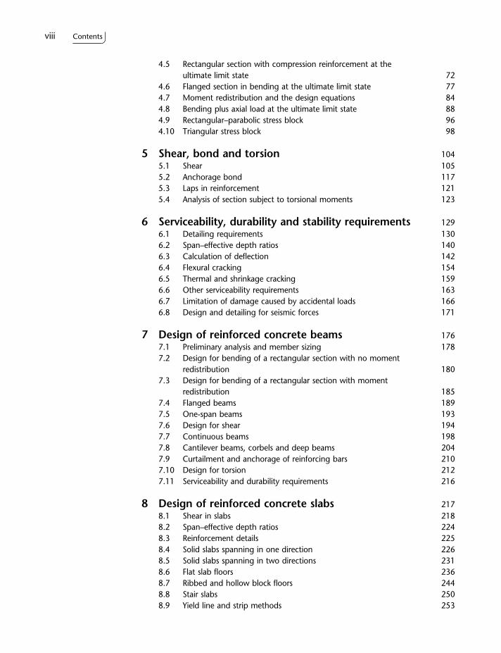
4.5 Rectangular section with compression reinforcement at theultimate limit state 72
4.6 Flanged section in bending at the ultimate limit state 774.7 Moment redistribution and the design equations 844.8 Bending plus axial load at the ultimate limit state 884.9 Rectangular–parabolic stress block 964.10 Triangular stress block 98
5 Shear, bond and torsion 1045.1 Shear 1055.2 Anchorage bond 1175.3 Laps in reinforcement 1215.4 Analysis of section subject to torsional moments 123
6 Serviceability, durability and stability requirements 1296.1 Detailing requirements 1306.2 Span–effective depth ratios 1406.3 Calculation of deflection 1426.4 Flexural cracking 1546.5 Thermal and shrinkage cracking 1596.6 Other serviceability requirements 1636.7 Limitation of damage caused by accidental loads 1666.8 Design and detailing for seismic forces 171
7 Design of reinforced concrete beams 1767.1 Preliminary analysis and member sizing 1787.2 Design for bending of a rectangular section with no moment
redistribution 1807.3 Design for bending of a rectangular section with moment
redistribution 1857.4 Flanged beams 1897.5 One-span beams 1937.6 Design for shear 1947.7 Continuous beams 1987.8 Cantilever beams, corbels and deep beams 2047.9 Curtailment and anchorage of reinforcing bars 2107.10 Design for torsion 2127.11 Serviceability and durability requirements 216
8 Design of reinforced concrete slabs 2178.1 Shear in slabs 2188.2 Span–effective depth ratios 2248.3 Reinforcement details 2258.4 Solid slabs spanning in one direction 2268.5 Solid slabs spanning in two directions 2318.6 Flat slab floors 2368.7 Ribbed and hollow block floors 2448.8 Stair slabs 2508.9 Yield line and strip methods 253
Contents ix
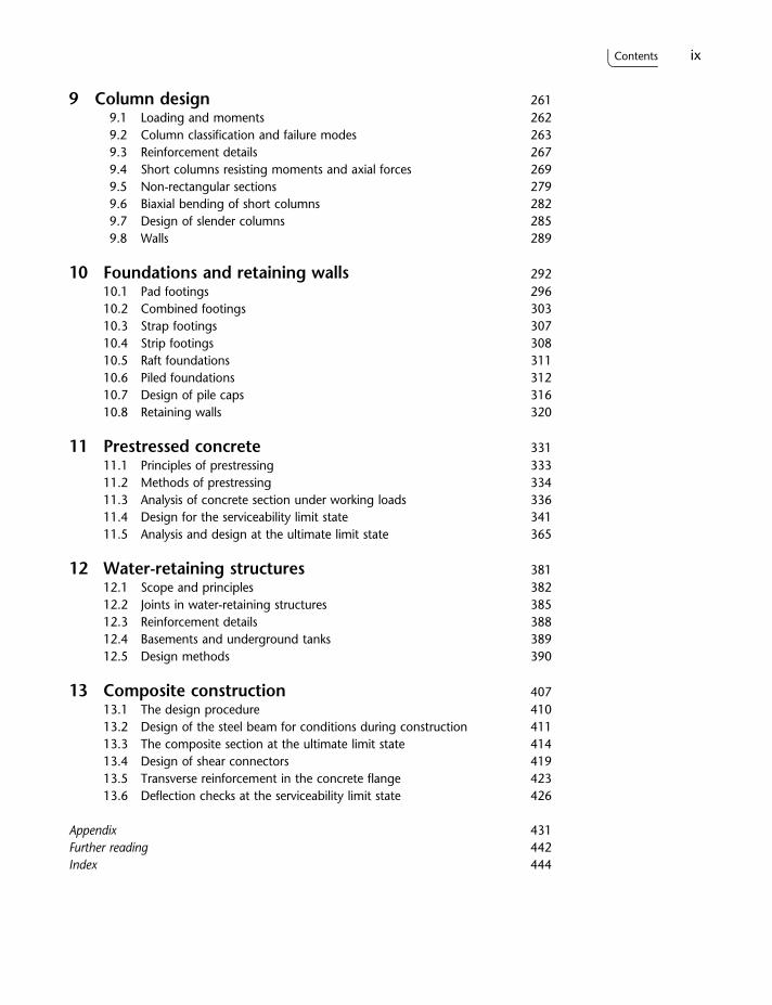
9 Column design 2619.1 Loading and moments 2629.2 Column classification and failure modes 2639.3 Reinforcement details 2679.4 Short columns resisting moments and axial forces 2699.5 Non-rectangular sections 2799.6 Biaxial bending of short columns 2829.7 Design of slender columns 2859.8 Walls 289
10 Foundations and retaining walls 29210.1 Pad footings 29610.2 Combined footings 30310.3 Strap footings 30710.4 Strip footings 30810.5 Raft foundations 31110.6 Piled foundations 31210.7 Design of pile caps 31610.8 Retaining walls 320
11 Prestressed concrete 33111.1 Principles of prestressing 33311.2 Methods of prestressing 33411.3 Analysis of concrete section under working loads 33611.4 Design for the serviceability limit state 34111.5 Analysis and design at the ultimate limit state 365
12 Water-retaining structures 38112.1 Scope and principles 38212.2 Joints in water-retaining structures 38512.3 Reinforcement details 38812.4 Basements and underground tanks 38912.5 Design methods 390
13 Composite construction 40713.1 The design procedure 41013.2 Design of the steel beam for conditions during construction 41113.3 The composite section at the ultimate limit state 41413.4 Design of shear connectors 41913.5 Transverse reinforcement in the concrete flange 42313.6 Deflection checks at the serviceability limit state 426
Appendix 431Further reading 442Index 444

1
1Introduction to design and propertiesof reinforced concrete
Chapter introductionStructural design may be considered as a series of interrelated and overlappingstages. In their simplest forms these consist of:
Conceptual design in which a range of potential structural forms and materialswill be considered.
Preliminary design which will typically involve simple and approximate handcalculations to assess the viability of a range of alternative conceptualsolutions.
Detailed design to include full analysis and calculations for the selectedscheme(s).
Reinforced concrete is a strong durable building material which can be formedinto many varied shapes and sizes, ranging from a simple rectangular beam orcolumn to a slender curved dome or shell. Its utility and versatility are achievedby combining the best features of concrete and steel.
This chapter can present only a brief introduction to the major issues to beconsidered in design, and the basic properties of concrete and its steelreinforcement. For a more comprehensive study it is recommended that referenceshould be made to the specialised texts and websites listed in Further Reading atthe end of the book.
2 Reinforced Concrete Design
1.1 Design processes
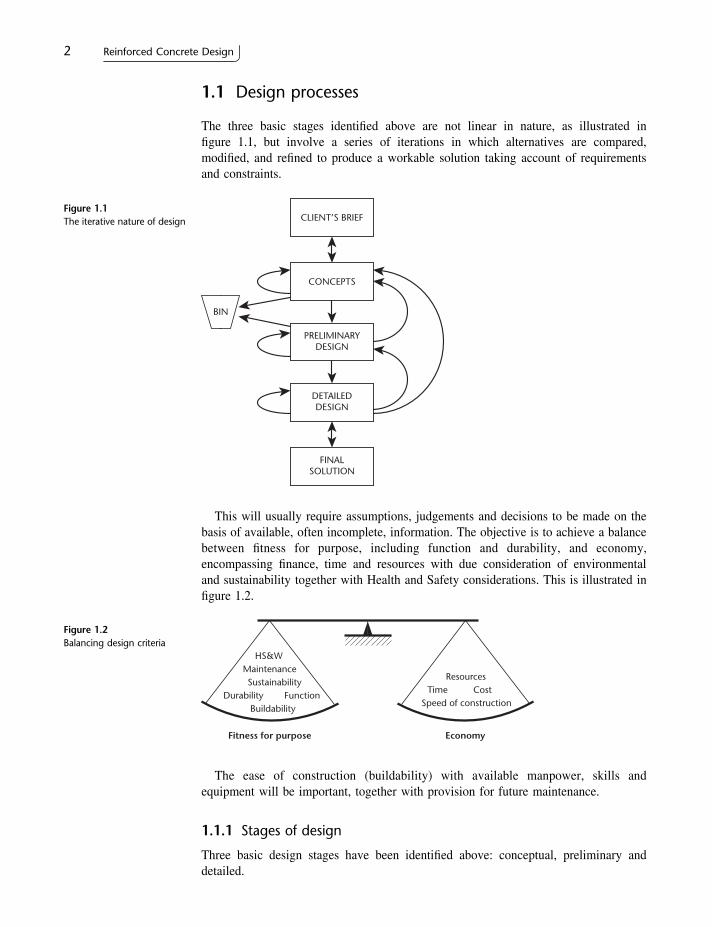
The three basic stages identified above are not linear in nature, as illustrated infigure 1.1, but involve a series of iterations in which alternatives are compared,modified, and refined to produce a workable solution taking account of requirementsand constraints.
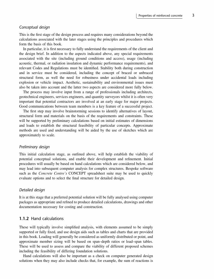
This will usually require assumptions, judgements and decisions to be made on thebasis of available, often incomplete, information. The objective is to achieve a balancebetween fitness for purpose, including function and durability, and economy,encompassing finance, time and resources with due consideration of environmentaland sustainability together with Health and Safety considerations. This is illustrated infigure 1.2.
The ease of construction (buildability) with available manpower, skills andequipment will be important, together with provision for future maintenance.
1.1.1 Stages of design
Three basic design stages have been identified above: conceptual, preliminary anddetailed.
Figure 1.1The iterative nature of design CLIENT’S BRIEF
CONCEPTS
PRELIMINARYDESIGN
DETAILEDDESIGN
FINALSOLUTION
BIN
Figure 1.2Balancing design criteria
Fitness for purpose
HS&WMaintenanceSustainability
Durability FunctionBuildability
Economy
ResourcesTime
Speed of constructionCost
Conceptual design
This is the first stage of the design process and requires many considerations beyond thecalculations associated with the later stages using the principles and procedures whichform the basis of this book.
In particular, it is first necessary to fully understand the requirements of the client andthe design brief. In addition to the aspects indicated above, any special requirementsassociated with the site (including ground conditions and access), usage (includingacoustic, thermal, or radiation insulation and dynamic performance requirements), andrelevant Codes and Regulations must be identified. Stability both during constructionand in service must be considered, including the concept of braced or unbracedstructural form, as well the need for robustness under accidental loads includingexplosion or vehicle impact. Aesthetic, sustainability and environmental issues mustalso be taken into account and the latter two aspects are considered more fully below.
The process may involve input from a range of professionals including architects,geotechnical engineers, services engineers, and quantity surveyors whilst it is often veryimportant that potential contractors are involved at an early stage for major projects.Good communications between team members is a key feature of a successful project.
The first step may involve brainstorming sessions to identify alternatives of layout,structural form and materials on the basis of the requirements and constraints. Thesewill be supported by preliminary calculations based on initial estimates of dimensionsand loads to establish the structural feasibility of particular concepts. Approximatemethods are used and understanding will be aided by the use of sketches which areapproximately to scale.
Preliminary design
This initial calculation stage, as outlined above, will help establish the viability ofpotential conceptual solutions, and enable their development and refinement. Initialprocedures will usually be based on hand calculations which are considered below, andmay lead into subsequent computer analysis for complex structures. Bespoke softwaresuch as the Concrete Centre’s CONCEPT spreadsheet suite may be used to quicklyevaluate options and to select the final structure for detailed design.
Detailed design
It is at this stage that a preferred potential solution will be fully analysed using computerpackages as appropriate and refined to produce detailed calculations, drawings and otherdocumentation necessary for costing and construction.
1.1.2 Hand calculations
These will typically involve simplified analysis, with elements assumed to be simplysupported or fully fixed, and use design aids such as tables and charts that are providedin this book. Loading will generally be considered as uniformly distributed or point, andapproximate member sizing will be based on span–depth ratios or load–span tables.These will be used to assess and compare the viability of different proposed schemesincluding the feasibility of differing foundation solutions.
Hand calculations will also be important as a check on computer generated designsolutions when they may also include checks that, for example, the sum of reactions is
Properties of reinforced concrete 3
equal to the applied load both at element and overall structure levels. Other usefulchecks include confirming that the increase in column loads at a floor level matches theload on the floor area supported and that the sum of (support + span) moments in a beamtotal wl 2=8 when carrying a uniformly distributed load (UDL) over the whole span.
Throughout this book are worked examples that emphasise the use of handcalculations such that the reader can gain a sound understanding of the fundamentalprinciples of reinforced and prestressed concrete design and the ability to carry out thoseroutine and non-routine design calculations that would be expected of a competentengineer.
1.1.3 Role of computers
In modern design offices the use of computer software is an accepted and intrinsic partof the design process and there are, indeed, many sophisticated packages andspreadsheet systems that are used to rapidly explore conceptual design options and tofinalise the detailed design. Such software is often linked to 2- and 3-dimensionalmodelling packages that aid visualisation and allow the electronic production ofaccurate construction and reinforcement detailing drawings. Through common databasesystems they can also facilitate the sharing of information between all parties involvedin the design and this may include engineers, architects and planners working indifferent offices in different parts of the world who can access, check and share eachothers’ work.
The ability to effectively use such software is a high-level skill in itself but it isgenerally recognised that it is unsafe practice for engineers to use sophisticated softwareif they themselves do not understand the fundamental engineering principles on whichthe software is based and cannot recognise, check and challenge computer output thatmay not be correct. For this reason this text focuses on the understanding andapplication of the engineering principles that underpin the design of reinforced andprestressed concrete such that, through gaining this understanding, the reader candevelop as a competent engineer who may or may not subsequently use sophisticatedcommercial software in their design work.
When using any form of computerised design system a competent designer willtherefore look for and check the following to ensure that reliable results are achieved:
Suitability of software to provide the required results for the particular problem mustbe established, including the effects of torsion and structural form. There must becompliance with appropriate Codes of Practice and any assumptions relating to thedetailed design procedures must be identified and approved. It may also be necessaryto check the relevance of stiffness values to ultimate or serviceability limit states.
Input data must be accurate including dimensions, materials properties, appliedloadings and member restraints.
Verification of output involving qualitative judgements such as:
are load paths sensible?is the deflected shape sensible?is there symmetry of output (e.g. reactions and moments) where there should be?based on experience, does the quantity and distribution of reinforcement, the sizeof members and so on seem sensible?
This will be supported by simple quantitative hand calculation checks as discussed insection 1.1.2.
4 Reinforced Concrete Design
Quality Systems that ensure calculations and designs are third-party checked and thatall parties who have access to the design data-base are aware of the consequences ofany design changes that have been made by any party.
1.1.4 Sustainability and environmental considerations.
Sustainable development is widely quoted as that which ‘meets the needs of the presentwithout compromising the ability of future generations to meet their own needs’.Engineers have a responsibility to contribute to the sustainability agenda by promotingsustainable methods of construction and, indeed, the Institution of Civil Engineers (ICE)promotes the concept that engineers are ‘at the heart of society, delivering sustainabledevelopment through knowledge, skills and professional expertise.’ It is, therefore, aresponsibility of the designer to embrace design methodologies that promote sustainablemethods of construction and the use of sustainable materials.
The choice of structural form and appropriate construction materials will be adecision that will balance many factors. However, choosing reinforced concreteconstruction will contribute significantly to the sustainability agenda. Concrete isgenerally locally sourced, requiring short travel distances to site, and can utilise wasteby-product materials of other industries such as fly ash. As a material it has a highthermal mass and reinforced concrete walls and floors can absorb, retain and releaseheat in domestic and commercial buildings, leading to a reduced requirement forheating and ventilating systems with reduced energy demands and associated CO2
emissions.Concrete is also a robust material, requiring little maintenance and providing good
fire, flood and sound resistance. The mass of reinforced concrete can ensure thatvibration effects are minimised; essential in buildings where there may be equipmentthat is sensitive to small movements. Concrete buildings can also be readily adapted foralternative use other than that for which originally intended and at the end of thestructure’s life the concrete can be crushed and recycled for other usages. Furtherinformation on sustainable concrete construction can be found in references 27 and 36.
1.1.5 Health, Safety and Welfare
The construction industry is, by its very nature, a dangerous place to work and it isgenerally recognised that each year there are many fatalities and major injuries thatcould be reduced in number and impact if appropriate action were taken by all parties tothe construction process.
As a result, in the UK and in many other parts of the world, issues of Health, Safetyand Welfare (HS&W) are given a high priority both at the Design and Constructionstages and throughout the in-service life of the structure. Indeed, the legal requirementto address such issues is defined in legislation which in the UK is partially driven by aEuropean Directive which specifies minimum health and safety requirements fortemporary or mobile construction sites.
The consequence of this Directive has been the introduction in 2007 of theConstruction Design and Management (CDM) regulations. The regulations aresupported by an Approved Code of Practice (ACoP) which has a special legal statusand gives advice to those involved in construction work such that, by following theadvice, compliance with the law may be assured.
The aim of CDM (2007) is to improve standards of HS&W through simplificationand clarification of regulations; improved co-operation and co-ordination of all parties
Properties of reinforced concrete 5
to the construction process and the planning and managing of work. The regulationsdefine and articulate the responsibility of all parties including the Client, the Designer,the Principal Contractor, other contractors, workers and the CDM coordinators.
The regulations also clearly define the responsibilities of the designer and, althoughthis text focuses on the principles of design of reinforced and prestressed concreteelements, the reader should be aware that when engaged in a design role they should benot only applying sound engineering judgements based on a knowledge of the principlesof design but should be designing in a way that is compliant with the CDM regulations.
A clear requirement of the regulations is that the designer should eliminate hazardsand reduce risks during design. The regulations are explicit that foreseeable risks shouldbe avoided although the designer cannot be held responsible for unforeseeable risks.Hence the designer must carry out a risk assessment through, for example, inspectingthe site to identify hazards, seeking relevant H&S information from the client, such asthe presence of buried contaminated materials, and co-ordinating their work with othersinvolved in the project to consider the H&S implications of the chosen design and theconsequential buildability issues.
Such buildability issues may include consideration of temporary works and detailedconstruction procedures such as sequence, pouring rates and prop removal, taking intoaccount access and equipment requirements. They must also take into account the safetyof the construction workforce which may influence, for example, the choice offoundation types where a deep foundation may necessitate work in potentiallyhazardous deep excavations whereas a shallow or piled foundation would be lesshazardous to the workforce. The final choice of foundation will, however, be ajudgement taking into account possible engineering solutions and cost together withbuildability issues linked to H&S considerations. Consideration must be given to H&Sissues arising from construction, maintenance and demolition and from the intendedusage of the building, excepting future usage that cannot reasonably be anticipated.
It is also a designer’s responsibility to provide information about any identified butremaining risks and communicate with all parties who may be affected by such risks.This must be communicated in an appropriate way, often in the form of annotation onthe designer’s drawings or in a written Designer’s Risk Assessment. While the designeris not expected to specify construction methods, when a design is based on theassumption of, for example, a particular sequence of construction then this informationmust be advised to the Contractor or a serious H&S issue may arise.
When a project is deemed to be notifiable the designer is also required to provideinformation for the project’s Health & Safety File, a statutory document held andmaintained by the Client in which health and safety information is recorded and kept forfuture reference when a project is completed.
1.2 Composite action
Concrete and steel have widely differing properties, some of which are listed below:
Concrete SteelStrength in tension poor goodStrength in compression good good, but slender bars will buckleStrength in shear fair goodDurability good corrodes if unprotectedFire resistance good poor – suffers rapid loss of strength at
high temperatures
6 Reinforced Concrete Design
It can be seen from this list that the materials are more or less complementary. Thus,when they are combined, the steel is able to provide the tensile strength and probablysome of the shear strength while the concrete, strong in compression, protects the steelto give it durability and fire resistance.
The tensile strength of concrete is only about 10 per cent of the compressive strength.Because of this, nearly all reinforced concrete structures are designed on the assumptionthat the concrete does not resist any tensile forces. Reinforcement is designed to carrythese tensile forces, which are transferred by bond between the interface of the twomaterials. If this bond is not adequate, the reinforcing bars will just slip within theconcrete and there will not be a composite action. Thus members should be detailedso that the concrete can be well compacted around the reinforcement duringconstruction. In addition, bars are normally ribbed so that there is an extramechanical grip.
In the analysis and design of the composite reinforced concrete section, it is assumedthat there is a perfect bond, so that the strain in the reinforcement is identical to thestrain in the adjacent concrete. This ensures that there is what is known as ‘compatibilityof strains’ across the cross-section of the member.
The coefficients of thermal expansion for steel and for concrete are of the order of10� 10�6 per 8C and 7–12�10�6 per 8C respectively. These values are sufficientlyclose that problems with bond seldom arise from differential expansion between the twomaterials over normal temperature ranges.
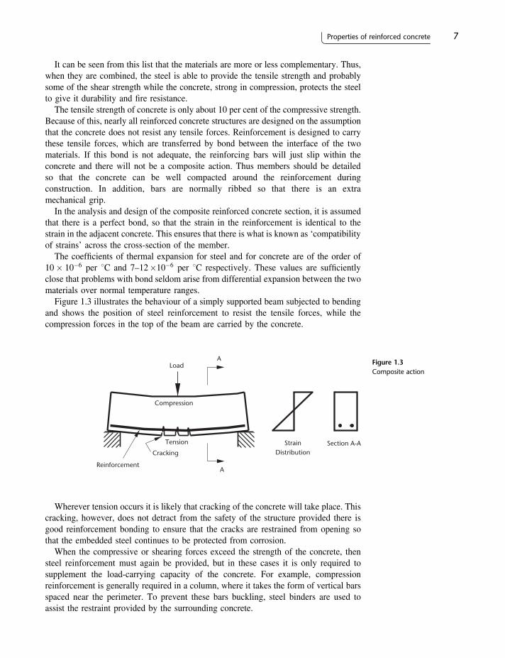
Figure 1.3 illustrates the behaviour of a simply supported beam subjected to bendingand shows the position of steel reinforcement to resist the tensile forces, while thecompression forces in the top of the beam are carried by the concrete.
Wherever tension occurs it is likely that cracking of the concrete will take place. Thiscracking, however, does not detract from the safety of the structure provided there isgood reinforcement bonding to ensure that the cracks are restrained from opening sothat the embedded steel continues to be protected from corrosion.
When the compressive or shearing forces exceed the strength of the concrete, thensteel reinforcement must again be provided, but in these cases it is only required tosupplement the load-carrying capacity of the concrete. For example, compressionreinforcement is generally required in a column, where it takes the form of vertical barsspaced near the perimeter. To prevent these bars buckling, steel binders are used toassist the restraint provided by the surrounding concrete.
Properties of reinforced concrete 7
Compression
Tension
Reinforcement
A
A
Cracking
Load
StrainDistribution
Section A-A
Figure 1.3Composite action
1.3 Stress–strain relations
The loads on a structure cause distortion of its members with resulting stresses andstrains in the concrete and the steel reinforcement. To carry out the analysis and designof a member it is necessary to have a knowledge of the relationship between thesestresses and strains. This knowledge is particularly important when dealing withreinforced concrete which is a composite material; for in this case the analysis of thestresses on a cross-section of a member must consider the equilibrium of the forces inthe concrete and steel, and also the compatibility of the strains across the cross-section.
1.3.1 Concrete
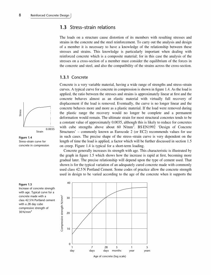
Concrete is a very variable material, having a wide range of strengths and stress–straincurves. A typical curve for concrete in compression is shown in figure 1.4. As the load isapplied, the ratio between the stresses and strains is approximately linear at first and theconcrete behaves almost as an elastic material with virtually full recovery ofdisplacement if the load is removed. Eventually, the curve is no longer linear and theconcrete behaves more and more as a plastic material. If the load were removed duringthe plastic range the recovery would no longer be complete and a permanentdeformation would remain. The ultimate strain for most structural concretes tends to bea constant value of approximately 0.0035, although this is likely to reduce for concreteswith cube strengths above about 60 N/mm2. BS EN1992 ‘Design of ConcreteStructures’ – commonly known as Eurocode 2 (or EC2) recommends values for usein such cases. The precise shape of the stress–strain curve is very dependent on thelength of time the load is applied, a factor which will be further discussed in section 1.5on creep. Figure 1.4 is typical for a short-term loading.
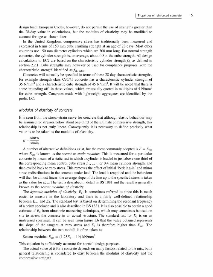
Concrete generally increases its strength with age. This characteristic is illustrated bythe graph in figure 1.5 which shows how the increase is rapid at first, becoming moregradual later. The precise relationship will depend upon the type of cement used. Thatshown is for the typical variation of an adequately cured concrete made with commonlyused class 42.5 N Portland Cement. Some codes of practice allow the concrete strengthused in design to be varied according to the age of the concrete when it supports the
8 Reinforced Concrete DesignSt
ress
Strain0.0035
Figure 1.4Stress–strain curve forconcrete in compression
Figure 1.5Increase of concrete strengthwith age. Typical curve for aconcrete made with aclass 42.5 N Portland cementwith a 28 day cubecompressive strength of30 N/mm2
40
30
20
10
01
day7
days28
days3
months1
year5
years
Com
pre
ssiv
e st
reng
th N
/mm
2
Age of concrete (log scale)
Properties of reinforced concrete 9
design load. European Codes, however, do not permit the use of strengths greater thanthe 28-day value in calculations, but the modulus of elasticity may be modified toaccount for age as shown later.
In the United Kingdom, compressive stress has traditionally been measured andexpressed in terms of 150 mm cube crushing strength at an age of 28 days. Most othercountries use 150 mm diameter cylinders which are 300 mm long. For normal strengthconcretes, the cylinder strength is, on average, about 0:8� the cube strength. All designcalculations to EC2 are based on the characteristic cylinder strength fck as defined insection 2.2.1. Cube strengths may however be used for compliance purposes, with thecharacteristic strength identified as fck; cube.
Concretes will normally be specified in terms of these 28-day characteristic strengths,for example strength class C35/45 concrete has a characteristic cylinder strength of35 N/mm2 and a characteristic cube strength of 45 N/mm2. It will be noted that there issome ‘rounding off’ in these values, which are usually quoted in multiples of 5 N/mm2
for cube strength. Concretes made with lightweight aggregates are identified by theprefix LC.
Modulus of elasticity of concrete
It is seen from the stress–strain curve for concrete that although elastic behaviour maybe assumed for stresses below about one-third of the ultimate compressive strength, thisrelationship is not truly linear. Consequently it is necessary to define precisely whatvalue is to be taken as the modulus of elasticity.
E ¼ stressstrain
A number of alternative definitions exist, but the most commonly adopted is E ¼ Ecm
where Ecm is known as the secant or static modulus. This is measured for a particularconcrete by means of a static test in which a cylinder is loaded to just above one-third ofthe corresponding mean control cube stress fcm; cube, or 0.4 mean cylinder strength, andthen cycled back to zero stress. This removes the effect of initial ‘bedding-in’ and minorstress redistributions in the concrete under load. The load is reapplied and the behaviourwill then be almost linear; the average slope of the line up to the specified stress is takenas the value for Ecm. The test is described in detail in BS 1881 and the result is generallyknown as the secant modulus of elasticity.
The dynamic modulus of elasticity, Ed, is sometimes referred to since this is mucheasier to measure in the laboratory and there is a fairly well-defined relationshipbetween Ecm and Ed. The standard test is based on determining the resonant frequencyof a prism specimen and is also described in BS 1881. It is also possible to obtain a goodestimate of Ed from ultrasonic measuring techniques, which may sometimes be used onsite to assess the concrete in an actual structure. The standard test for Ed is on anunstressed specimen. It can be seen from figure 1.6 that the value obtained representsthe slope of the tangent at zero stress and Ed is therefore higher than Ecm. Therelationship between the two moduli is often taken as
Secant modulus Ecm ¼ ð1:25Ed � 19Þ kN/mm2
This equation is sufficiently accurate for normal design purposes.The actual value of E for a concrete depends on many factors related to the mix, but a
general relationship is considered to exist between the modulus of elasticity and thecompressive strength.

Typical values of Ecm for various concrete classes using gravel aggregates which aresuitable for design are shown in table 1.1. For limestone aggregates these values shouldbe reduced by a factor of 0.9, or for basalt increased by a factor of 1.2. The magnitude ofthe modulus of elasticity is required when investigating the deflection and cracking of astructure. When considering short-term effects, member stiffness will be based on thestatic modulus Ecm defined above. If long-term effects are being considered, it can beshown that the effect of creep can be represented by modifying the value of Ecm to aneffective value Ec; eff , and this is discussed in section 6.3.2.
The elastic modulus at an age other than 28 days may be estimated from this table byusing the anticipated strength value at that age. If a typical value of Poisson’s ratio isneeded, this should be taken as 0.2 for regions which are not subject to tension cracking.
1.3.2 Steel
Figure 1.7 shows typical stress–strain curves for (a) hot rolled high yield steel, and(b) cold-worked high yield steel. Mild steel behaves as an elastic material, with thestrain proportional to the stress up to the yield, at which point there is a sudden increasein strain with no change in stress. After the yield point, this becomes a plastic materialand the strain increases rapidly up to the ultimate value. High yield steel, which is mostcommonly used for reinforcement, may behave in a similar manner or may, on the other
10 Reinforced Concrete Design
Figure 1.6Moduli of elasticity ofconcrete
tangent or dynamic modulus
secant or static modulusSt
ress
0.4fcm
Strain
Table 1.1 Short-term modulus of elasticity of normal-weight gravel concrete
28 day characteristic strength (N/mm2)fck=fck; cube (cylinder/cube)
Static (secant) modulusEcm (kN/mm2)
Mean
20/25 3025/30 3130/37 3335/45 3440/50 3545/55 3650/60 3760/75 3970/85 4180/95 4290/105 44

Properties of reinforced concrete 11
hand, not have such a definite yield point but may show a more gradual change fromelastic to plastic behaviour and reduced ductility depending on the manufacturingprocess. All materials have a similar slope of the elastic region with elastic modulusEs ¼ 200 kN/mm2 approximately.
The specified strength used in design is based on either the yield stress or a specifiedproof stress. A 0.2 per cent proof stress is defined in figure 1.7 by the broken line drawnparallel to the linear part of the stress–strain curve.
Removal of the load within the plastic range would result in the stress–strain diagramfollowing a line approximately parallel to the loading portion – see line BC in figure 1.8.The steel will be left with a permanent strain AC, which is known as ‘slip’. If the steel isagain loaded, the stress–strain diagram will follow the unloading curve until it almostreaches the original stress at B and then it will curve in the direction of the first loading.Thus, the proportional limit for the second loading is higher than for the initial loading.This action is referred to as ‘strain hardening’ or ‘work hardening’.
The load deformation of the steel is also dependent on the length of time the load isapplied. Under a constant stress the strains will gradually increase – this phenomenon isknown as ‘creep’ or ‘relaxation’. The amount of creep that takes place over a period oftime depends on the grade of steel and the magnitude of the stress. Creep of the steel isof little significance in normal reinforced concrete work, but it is an important factor inprestressed concrete where the prestressing steel is very highly stressed.
1.4 Shrinkage and thermal movement
As concrete hardens there is a reduction in volume. This shrinkage is liable to causecracking of the concrete, but it also has the beneficial effect of strengthening the bondbetween the concrete and the steel reinforcement. Shrinkage begins to take place assoon as the concrete is mixed, and is caused initially by the absorption of the water bythe concrete and the aggregate. Further shrinkage is caused by evaporation of the waterwhich rises to the concrete surface. During the setting process the hydration of thecement causes a great deal of heat to be generated, and as the concrete cools, furthershrinkage takes place as a result of thermal contraction. Even after the concrete hashardened, shrinkage continues as drying out persists over many months, and anysubsequent wetting and drying can also cause swelling and shrinkage. Thermalshrinkage may be reduced by restricting the temperature rise during hydration, whichmay be achieved by the following procedures:
1. Use a mix design with a low cement content or suitable cement replacement e.g. flyash (pulverised fuel ash) or ground granulated blast furnace slag.
0.002
Stre
ss
0.2% proofstress
Strain Strain
Stre
ssYield stress
(a) Hot rolled steel (b) Cold worked steel
Figure 1.7Stress–strain curves for highyield reinforcing steel
Stre
ss
A
B
C Strain
Figure 1.8Strain hardening

12 Reinforced Concrete Design
2. Avoid rapid hardening and finely ground cement if possible.
3. Keep aggregates and mixing water cool.
4. Use steel shuttering and cool with a water spray.
5. Strike the shuttering early to allow the heat of hydration to dissipate.
A low water–cement ratio will help to reduce drying shrinkage by keeping to aminimum the volume of moisture that can be lost.
If the change in volume of the concrete is allowed to take place freely and withoutrestraint, there will be no stress change within the concrete. Restraint of the shrinkage,on the other hand, will cause tensile strains and stresses. The restraint may be causedexternally by fixity with adjoining members or friction against an earth surface, andinternally by the action of the steel reinforcement. For a long wall or floor slab, therestraint from adjoining concrete may be reduced by constructing successive baysinstead of alternate bays. This allows the free end of every bay to contract before thenext bay is cast.
Day-to-day thermal expansion of the concrete can be greater than the movementscaused by shrinkage. Thermal stresses and strains may be controlled by the correctpositioning of movement or expansion joints in a structure. For example, the jointsshould be placed at an abrupt change in cross-section and they should, in general, passcompletely through the structure in one plane.
When the tensile stresses caused by shrinkage or thermal movement exceed thestrength of the concrete, cracking will occur. To control the crack widths, steelreinforcement must be provided close to the concrete surface; the codes of practicespecify minimum quantities of reinforcement in a member for this purpose.
Calculation of stresses induced by shrinkage
(a) Shrinkage restrained by the reinforcement
The shrinkage stresses caused by reinforcement in an otherwise unrestrained membermay be calculated quite simply. The member shown in figure 1.9 has a free shrinkagestrain of "cs if made of plain concrete, but this overall movement is reduced by theinclusion of reinforcement, giving a compressive strain "sc in the steel and causing aneffective tensile strain "ct the concrete.
Figure 1.9Shrinkage strains
εcs
εct
εct
Original member –as cast
Plain concrete –unrestrained
Reinforced concrete –unrestrained
Reinforced concrete –fully restrained
ε sc
Properties of reinforced concrete 13
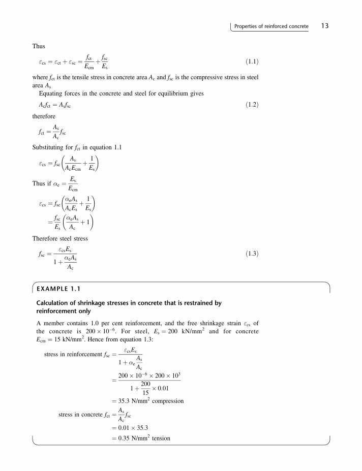
Thus
"cs ¼ "ct þ "sc ¼fct
Ecmþ fsc
Esð1:1Þ
where fct is the tensile stress in concrete area Ac and fsc is the compressive stress in steelarea As
Equating forces in the concrete and steel for equilibrium gives
Acfct ¼ Asfsc ð1:2Þtherefore
fct ¼As
Acfsc
Substituting for fct in equation 1.1
"cs ¼ fscAs
AcEcmþ 1
Es
� �
Thus if �e ¼Es
Ecm
"cs ¼ fsc�eAs
AcEsþ 1
Es
� �
¼ fscEs
�eAs
Acþ 1
� �
Therefore steel stress
fsc ¼"csEs
1þ �eAs
Ac
ð1:3Þ
EXAMPLE 1.1
Calculation of shrinkage stresses in concrete that is restrained byreinforcement only
A member contains 1.0 per cent reinforcement, and the free shrinkage strain "cs ofthe concrete is 200� 10�6. For steel, Es ¼ 200 kN/mm2 and for concreteEcm ¼ 15 kN/mm2. Hence from equation 1.3:
stress in reinforcement fsc ¼"csEs
1þ �eAs
Ac
¼ 200� 10�6 � 200� 103
1þ 20015� 0:01
¼ 35:3 N/mm2 compression
stress in concrete fct ¼As
Acfsc
¼ 0:01� 35:3
¼ 0:35 N/mm2 tension
14 Reinforced Concrete Design
The stresses produced in members free from external restraint are generally small asin example 1.1, and can be easily withstood both by the steel and the concrete.
(b) Shrinkage fully restrained
If the member is fully restrained, then the steel cannot be in compression since "sc ¼ 0and hence fsc ¼ 0 (figure 1.9). In this case the tensile strain induced in the concrete "ct
must be equal to the free shrinkage strain "cs, and the corresponding stress will probablybe high enough to cause cracking in immature concrete.
EXAMPLE 1.2
Calculation of fully restrained shrinkage stresses
If the member in example 1.1 were fully restrained, the stress in the concrete would begiven by
fct ¼ "ctEcm
where
"ct ¼ "cs ¼ 200� 10�6
then
fct ¼ 200� 10�6 � 15� 103
¼ 3:0N/mm2
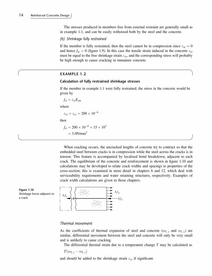
When cracking occurs, the uncracked lengths of concrete try to contract so that theembedded steel between cracks is in compression while the steel across the cracks is intension. This feature is accompanied by localised bond breakdown, adjacent to eachcrack. The equilibrium of the concrete and reinforcement is shown in figure 1.10 andcalculations may be developed to relate crack widths and spacings to properties of thecross-section; this is examined in more detail in chapters 6 and 12, which deal withserviceability requirements and water retaining structures, respectively. Examples ofcrack width calculations are given in those chapters.
Thermal movement
As the coefficients of thermal expansion of steel and concrete (�T; s and �T; c) aresimilar, differential movement between the steel and concrete will only be very smalland is unlikely to cause cracking.
The differential thermal strain due to a temperature change T may be calculated as
Tð�T; c � �T; sÞand should be added to the shrinkage strain "cs if significant.
Figure 1.10Shrinkage forces adjacent toa crack
Asfst
Acfct
Asfsc

Properties of reinforced concrete 15
The overall thermal contraction of concrete is, however, frequently effective inproducing the first crack in a restrained member, since the required temperature changescould easily occur overnight in a newly cast member, even with good control of the heatgenerated during the hydration processes.
EXAMPLE 1.3
Thermal shrinkage
Find the fall in temperature required to cause cracking in a restrained member if ultimatetensile strength of the concrete fct; eff ¼ 2 N/mm2, Ecm ¼ 16 kN/mm2 and�T; c ¼ �T; s ¼ 10� 10�6 per 8C.
Ultimate tensile strain of concrete
"ult ¼fct; effEcm
¼ 216� 103
¼ 125� 10�6
Minimum temperature drop to cause cracking
¼ "ult
�T; c¼ 125
10¼ 12:58C
It should be noted that full restraint, as assumed in this example, is unlikely to occurin practice; thus the temperature change required to cause cracking is increased. Amaximum ‘restraint factor’ of 0.5 is often used, with lower values where externalrestraint is likely to be small. The temperature drop required would then be given by thetheoretical minimum divided by the ‘restraint factor’. i.e. 12:5=0:5 ¼ 258C in thisexample. Restraint factors and their use are considered more fully in chapters 6 and 12.
1.5 Creep
Creep is the continuous deformation of a member under sustained load. It is aphenomenon associated with many materials, but it is particularly evident with concrete.The precise behaviour of a particular concrete depends on the aggregates and the mixdesign as well as the ambient humidity, member cross-section, and age at first loading,but the general pattern is illustrated by considering a member subjected to axialcompression. For such a member, a typical variation of deformation with time is shownby the curve in figure 1.11.
The characteristics of creep are
1. The final deformation of the member can be three to four times the short-termelastic deformation.
2. The deformation is roughly proportional to the intensity of loading and to theinverse of the concrete strength.
3. If the load is removed, only the instantaneous elastic deformation will recover – theplastic deformation will not.
4. There is a redistribution of load between the concrete and any steel present.
Def
orm
atio
n
1 2 3 4 5Time – years
Short-termelastic
Creep
Figure 1.11Typical increase ofdeformation with time forconcrete
16 Reinforced Concrete Design
The redistribution of load is caused by the changes in compressive strains beingtransferred to the reinforcing steel. Thus the compressive stresses in the steel areincreased so that the steel takes a larger proportion of the load.
The effects of creep are particularly important in beams, where the increaseddeflections may cause the opening of cracks, damage to finishes, and the non-alignmentof mechanical equipment. Redistribution of stress between concrete and steel occursprimarily in the uncracked compressive areas and has little effect on the tensionreinforcement other than reducing shrinkage stresses in some instances. The provisionof reinforcement in the compressive zone of a flexural member, however, often helps torestrain the deflections due to creep.
1.6 Durability
Concrete structures, properly designed and constructed, are long lasting and shouldrequire little maintenance. The durability of the concrete is influenced by
1. the exposure conditions;
2. the cement type;
3. the concrete quality;
4. the cover to the reinforcement;
5. the width of any cracks.
Concrete can be exposed to a wide range of conditions such as the soil, sea water,de-icing salts, stored chemicals or the atmosphere. The severity of the exposure governsthe type of concrete mix required and the minimum cover to the reinforcing steel.Whatever the exposure, the concrete mix should be made from impervious andchemically inert aggregates. A dense, well-compacted concrete with a low water–cement ratio is all important and for some soil conditions it is advisable to use a sulfate-resisting cement. Air entrainment is usually specified where it is necessary to cater forrepeated freezing and thawing.
Adequate cover is essential to prevent corrosive agents reaching the reinforcementthrough cracks and pervious concrete. The thickness of cover required depends on theseverity of the exposure and the quality of the concrete (as shown in table 6.2). Thecover is also necessary to protect the reinforcement against a rapid rise in temperatureand subsequent loss of strength during a fire. Part 1.2 of EC2 provides guidance on thisand other aspects of fire design. Durability requirements with related design calculationsto check and control crack widths and depths are described in more detail in chapter 6.
1.7 Specification of materials
1.7.1 Concrete
The selection of the type of concrete is frequently governed by the strength required,which in turn depends on the intensity of loading and the form and size of the structuralmembers. For example, in the lower columns of a multi-storey building a higher-strength concrete may be chosen in preference to greatly increasing the size of thecolumn section with a resultant loss in clear floor space.
Properties of reinforced concrete 17
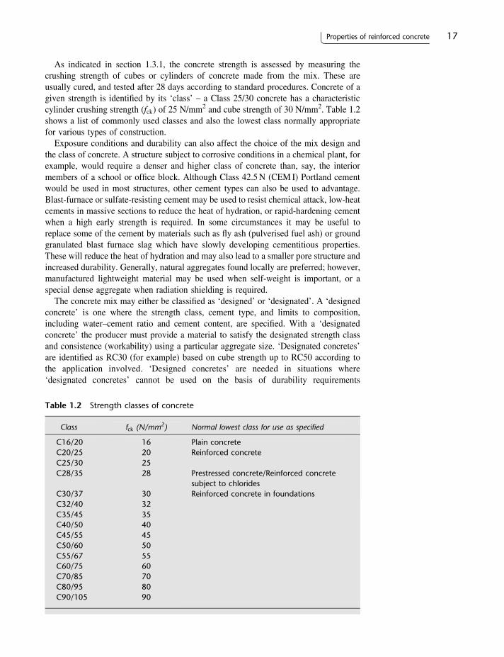
As indicated in section 1.3.1, the concrete strength is assessed by measuring thecrushing strength of cubes or cylinders of concrete made from the mix. These areusually cured, and tested after 28 days according to standard procedures. Concrete of agiven strength is identified by its ‘class’ – a Class 25/30 concrete has a characteristiccylinder crushing strength (fck) of 25 N/mm2 and cube strength of 30 N/mm2. Table 1.2shows a list of commonly used classes and also the lowest class normally appropriatefor various types of construction.
Exposure conditions and durability can also affect the choice of the mix design andthe class of concrete. A structure subject to corrosive conditions in a chemical plant, forexample, would require a denser and higher class of concrete than, say, the interiormembers of a school or office block. Although Class 42.5N (CEM I) Portland cementwould be used in most structures, other cement types can also be used to advantage.Blast-furnace or sulfate-resisting cement may be used to resist chemical attack, low-heatcements in massive sections to reduce the heat of hydration, or rapid-hardening cementwhen a high early strength is required. In some circumstances it may be useful toreplace some of the cement by materials such as fly ash (pulverised fuel ash) or groundgranulated blast furnace slag which have slowly developing cementitious properties.These will reduce the heat of hydration and may also lead to a smaller pore structure andincreased durability. Generally, natural aggregates found locally are preferred; however,manufactured lightweight material may be used when self-weight is important, or aspecial dense aggregate when radiation shielding is required.
The concrete mix may either be classified as ‘designed’ or ‘designated’. A ‘designedconcrete’ is one where the strength class, cement type, and limits to composition,including water–cement ratio and cement content, are specified. With a ‘designatedconcrete’ the producer must provide a material to satisfy the designated strength classand consistence (workability) using a particular aggregate size. ‘Designated concretes’are identified as RC30 (for example) based on cube strength up to RC50 according tothe application involved. ‘Designed concretes’ are needed in situations where‘designated concretes’ cannot be used on the basis of durability requirements
Table 1.2 Strength classes of concrete
Class fck (N/mm2) Normal lowest class for use as specified
C16/20C20/25C25/30C28/35
C30/37C32/40C35/45C40/50C45/55C50/60C55/67C60/75C70/85C80/95C90/105
16202528
3032354045505560708090
Plain concreteReinforced concrete
Prestressed concrete/Reinforced concretesubject to chloridesReinforced concrete in foundations

18 Reinforced Concrete Design
(e.g. chloride-induced corrosion). Detailed requirements for mix specification andcompliance are given by BS EN206 ‘Concrete – Performance, Production, Placing andCompliance Criteria’ and BS8500 ‘Concrete – Complementary British Standard toBS EN206’.
1.7.2 Reinforcing steel
Table 1.3 lists the characteristic design strengths of some of the more common types ofreinforcement currently used in the UK. Grade 500 (500N/mm2 characteristic strength)has replaced Grade 250 and Grade 460 reinforcing steel. EC2 permits the use ofreinforcement of up to Grade 600. The nominal size of a bar is the diameter of anequivalent circular area.
Grade 250 bars are hot-rolled mild-steel bars which usually have a smooth surface sothat the bond with the concrete is by adhesion only. This type of bar can be more readilybent, so they have in the past been used where small radius bends are necessary, such aslinks in narrow beams or columns, but plain bars are not now recognised in theEuropean Union and they are no longer available for general use in the UK.
High-yield bars are manufactured with a ribbed surface or in the form of a twistedsquare. Square twisted bars have inferior bond characteristics and have been used in thepast, although they are now obsolete. Deformed bars have a mechanical bond with theconcrete, thus enhancing ultimate bond stresses as described in section 5.2. The bendingof high-yield bars through a small radius is liable to cause tension cracking of the steel,and to avoid this the radius of the bend should not be less than two times the nominalbar size for small bars (�16 mm) or 3½ times for larger bars (see figure 5.11). Theductility of reinforcing steel is also classified for design purposes. Ribbed high yieldbars may be classified as:
Class A – which is normally associated with small diameter (�12 mm) cold-workedbars used in mesh and fabric. This is the lowest ductility category and will includelimits on moment redistribution which can be applied (see section 4.7) and higherquantities for fire resistance.Class B – which is most commonly used for reinforcing bars.Class C – high ductility which may be used in earthquake design or similar situations.
Floor slabs, walls, shells and roads may be reinforced with a welded fabric ofreinforcement, supplied in rolls and having a square or rectangular mesh. This can givelarge economies in the detailing of the reinforcement and also in site labour costs ofhandling and fixing. Prefabricated reinforcement bar assemblies are also becoming
Table 1.3 Strength of reinforcement
Designation Normal sizes (mm)Specified characteristicstrength fyk (N/mm2)
Hot-rolled high yield(BS4449)Cold-worked high yield(BS4449)
All sizes
Up to and including 12
500
500
BS4449 should be used in conjunction with BS EN10080.
Properties of reinforced concrete 19
increasingly popular for similar reasons. Welded fabric mesh made of ribbed wiregreater than 6 mm diameter may be of any of the ductility classes listed above.
The cross-sectional areas and perimeters of various sizes of bars, and the cross-sectional area per unit width of slabs are listed in the Appendix. Reinforcing bars in amember should either be straight or bent to standard shapes. These shapes must be fullydimensioned and listed in a schedule of the reinforcement which is used on site for thebending and fixing of the bars. Standard bar shapes and a method of scheduling arespecified in BS8666. The bar types as previously described are commonly identified bythe following codes: H for high yield steel, irrespective of ductility class or HA, HB, HCwhere a specific ductility class is required; this notation is generally used throughoutthis book.
Index
Actionscharacteristic 23combination 28, 35, 293, 322–3,
325design values 29–32frequent 28,permanent 24, 34quasi-permanent 28, 392typical values 431, 432variable 28, 34
Age factors 10Analysis of structures
beams 36–42column moments 49, 53damaged structure 166, 170frames 43–53lateral loads 50retaining walls 320–30
Analysis of the sectionbending 65–88elastic 98, 336–40flanged 77–84uncracked 101with axial load 88–96
Anchorage bond 117–21bond lengths 117, 210, 435
Areas of bars 137–9, 432–4
Balanced failure 69, 91Bars see ReinforcementBasements 389Bases see FootingsBasic control perimeter 219, 299Beams
analysis of moments and shears 36analysis of sections 63–103cantilever 204
continuous 38–42, 198–204deep 209deflections 142–52design 68, 176–216design charts 69, 75doubly reinforced 72, 183–5,
187–9effective spans 178flanged 189–93one-span 37, 181–94prestressed 331–80seismic design 171reinforcement details 195–8,
210–12singly reinforced 68, 181–3, 186sizing 178–80, 344
Bearing pressures 295–8, 324Bending moments
coefficients 42, 218, 232, 235, 238envelopes, 41, 48redistribution 58–62, 84, 185–9
Bending with axial load 88–96,269–77
Bends and hooks 120Bent-up bars 113–14, 198Biaxial bending 282–4Bond, anchorage 117Bond lengths 117–21Braced columns 262Bundled bars 137, 140
Cantilever beams 204Cantilever retaining walls 321–3,
326–30Characteristic actions, 23Characteristic material strengths 17,
18, 22, 366
444
Circumference of bars 432Coefficients of bending moments and
shears 42, 218, 232, 235, 238Columns
analysis of section 88–96axially loaded 88, 262biaxial bending 282–4braced 262design 261–89design charts 90, 269–74effective height 263–4loading arrangements 49, 262moments 49, 262non-rectangular section 279–82non-sway 262reinforcement details 267–9short 263–6, 269–84simplified design 277–9, 280slender 263–7, 285–9substitute frame 43–4, 49, 272–3unsymmetrically reinforced 274–9
Combined footings 303–6Composite construction
design 407–30serviceability limit state 411–12, 414,
426–30shear connectors 419–26transverse reinforcement 423types 407–9ultimate limit state 410–12, 414–18
Compression reinforcement 72–7, 187–9Conceptual design 1–3Computers, role of 4–5Concrete
age factor 10characteristic strength 17class 17, 132, 296, 383cover 130–6, 296, 383, 389cracking 12–15, 154–63, 382–3, 390–4creep 15, 145–6, 356durability 16, 216elastic modulus 9,shrinkage 11, 146, 159, 356, 393–5strength class 17, 132, 296, 383stress–strain curve 8, 64tensile strength 144thermal expansion 14, 159–60
Continuous beamsanalysis 38–42curtailment of bars 210–12design 198–204envelopes 42–8loading arrangements 35moment and shear coefficients 42
Corbels 205–8Counterfort retaining walls 321Cover to reinforcement 130–6, 296, 383,
389Cracking
control 159, 384–5direct tensile 392flexural 154–9, 391–2thermal and shrinkage 159, 393–5
Creep 15, 145, 356Creep coefficients 146Critical section 111, 299, 317Curtailment of bars 210–12Curvatures 143, 145
Deep beams 209Deflections 142–52, 359–62Design charts
beams 69, 75, 437columns 90, 269–74, 439
Design stagesconceptual 1–3detailed 1–3preliminary 1–3
Diagonal tension 105Distribution steel 225, 226Doubly reinforced beams 72, 183–5,
187–9Dowels 298Ductility 18, 172Durability 16, 163, 216, 383
Earth-bearing pressures 295–7, 324Effective depth 66, 178Effective flange width 189–90Effective height of a column 263–4Effective span 178Elastic analysis of a section 98, 336–40Elastic modulus
concrete 9–10steel 11
End blocks 363–5Envelopes, bending moment and shear
force 42, 48Equivalent rectangular stress block 66
Factors of safetyglobal 32partial 23, 31, 293, 294, 383, 390,
392Fire resistance 133–6, 165, 237, 290Flanged section see T-beamsFlat slab 236–44Floors see Slabs
Index 445
Footingsallowable soil pressures 295combined 303–6factors of safety 293–4horizontal loads 315on rock 298pad 296–303piled 312–20plain concrete 296raft 311–12seismic forces 173–4strap 307–8strip 308–11
Foundations see FootingsFrames
analysis 43–53braced 43–9laterally loaded 50–3loading arrangements 43, 44, 50non-sway 43unbraced 50
Gravity retaining walls 320, 322
Hand calculations 3–4Health, safety and welfare 2, 5–6, 336,
385Hooks and bends 120
Jointsconstruction 385–6contraction and expansion 386–8
Lap lengths 121–3, 435Laps 121–3L-beams 189–90Lever arm 68Lever-arm curve 69, 182, 437Limit state design 20–32Limit states
serviceability 21ultimate 21
Links 105, 109–11, 194–6, 268–9, 373–6Loads see ActionsLoading arrangements 35, 262Long-term deflection 142–5, 361Loss of prestress 354–9
Magnel diagram 349–51Material properties 6–18, 22Maximum bar sizes 139, 392Maximum bar spacing 136, 225, 267, 389,
393
Maximum steel areas 138, 225, 267–8,435
Minimum bar spacing 137, 225, 267–8Minimum cover 130–6, 296, 383Minimum member dimensions 133Minimum steel areas 137, 225, 267–8,
436Modular ratio 13, 99–103, 145, 355Modulus of elasticity see Elastic modulusMoment coefficients 42, 218, 232, 235,
238Moment envelopes 42, 48Moment redistribution 58–62, 84, 185–9Moments in columns 262–89
Neutral-axis depth 66–9, 86Nominal reinforcement 111, 137, 195,
436Non-rectangular section 279–82
Overturning 26, 322–33
Pad footings 296–303Parabola, properties of 97Partial safety factors 23, 24 , 64, 293, 294,
383, 390, 392Permissible bearing pressures 295Permissible stresses 20, 335, 405Piled foundations 312–20Plain concrete footings 296Prestressed concrete
analysis and design 331–80cable zone 352–4deflections 359–62end block 363–5losses 354–9Magnel diagram 349–51post-tensioning 336pretensioning 334–5shear 371–80transfer stress 342–3ultimate strength 365–71
Punching shear 219–24, 239, 299–303,318, 438
Raft foundations 311–12Rectangular stress block 67Rectangular–parabolic stress block 66, 96Redistribution of moments 58–62, 84,
185–9Reinforcement
areas 137–9, 432–4bond lengths 117–21, 435characteristic strengths 18
446 Index
circumference 432lap lengths 121–3, 435maximum and minimum areas 137,
138, 225, 267–8, 435, 436properties 10, 18side face 139spacing 136, 137, 225, 268, 290, 389,
393, 397surface 139torsion 123–8, 212–15untensioned 369–71
Restraint factors 15, 161Retaining walls
analysis and design 322–30cantilever 321, 323–30counterfort 321gravity 320–2
Seismic forces, design and detailingfor 171–5
Serviceability limit statecracking 154–9, 341–2, 384–5, 390–5deflections 142–52, 359–62durability 16, 163, 216, 383factors of safety 31–2fire resistance 133–6, 165, 237, 290
Shearadditional longitudinal force 110, 196,
391beams 105, 194–204, 438concrete stresses 219flanged sections 115, 189–92, 423footings 299–302prestressed beams 371–80punching 219–24, 239, 299–303, 318,
438reinforcement 109, 195–8, 221–4,
373–80, 433slabs 218–24torsion 127, 212–15variable strut inclination
method 106–14Shear wall structures
coupling beams 57, 174reinforcement design 289–90resisting horizontal loads 53–7with openings 57with structural frames 57–8
Short columns 263–6, 269–84Shrinkage 11, 145, 159, 356, 393–5Slabs
continuous, spanning onedirection 229–31
flat 236–44
hollow block 244–50one span, spanning one direction 226–9ribbed 244–50seismic design 175spanning two directions 231–6stair 250–3strip method 253, 259–60yield lines 253–8
Slender columns 263–7, 285–9Spacing of reinforcement 136, 137, 225,
268, 290, 389, 393, 436Span–effective depth ratios 140, 152,
224–5, 436Stability 166–70, 322Stairs 250–3Steel
characteristic stresses 18stress–strain curve 10, 65, 366yield strains 11, 65
Stirrups see LinksStrap footings 307–8Stress blocks 66, 96, 99Stresses
anchorage 117, 363–5bond 118concrete, characteristic 17permissible 20, 335, 405shear 219steel, characteristic 18
Stress–strain curves 8, 10, 11, 64, 65,366
Strip footings 308–11Strip method 253, 259–60Substitute frame
braced 44column 49continuous beam 43–8
Sustainability 2, 5
T-beamsanalysis 77–84design 189–93flange reinforcement 115, 190–2flange width 189span–effective depth ratio 140
Tendons 333–5Thermal cracking 159, 383–4, 393–5Thermal movement 11, 14, 384–5Tie forces 166–70Torsion
analysis 123–8complex shapes 126design 212–15, 438with bending and shear 127, 212–15
Index 447
Transfer stresses 342–3Transmission length 335Triangular stress block 93
Ultimate limit statefactors of safety 24, 293, 383loading arrangements 26–30, 322–3,
325prestressed concrete 365–71stability 322–3, 383, 385
Uncracked section 101, 144, 372Untensioned steel in prestressed
concrete 369–71
Walls 289–91Water-retaining structures
basements 389–90buoyancy 383classes 382design methods 390–406factors of safety 383, 390, 392joints 385–8reinforcement details 388–9, 394underground tanks 389–90
Weights of materials 431Wind loading 30, 35, 50
Yield lines 253–8Yield strains 11, 65
448 Index