0.1 MM RESOLUTION · mt50s13a0604b ORDER CODES (NOT ALL COMBINATION AVALIABLE) Nivelco reserves the...
6
MAGNETOSTRICTIVE LEVEL TRANSMITTERS LEVEL TRANSMITTERS 0.1 MM RESOLUTION
Transcript of 0.1 MM RESOLUTION · mt50s13a0604b ORDER CODES (NOT ALL COMBINATION AVALIABLE) Nivelco reserves the...
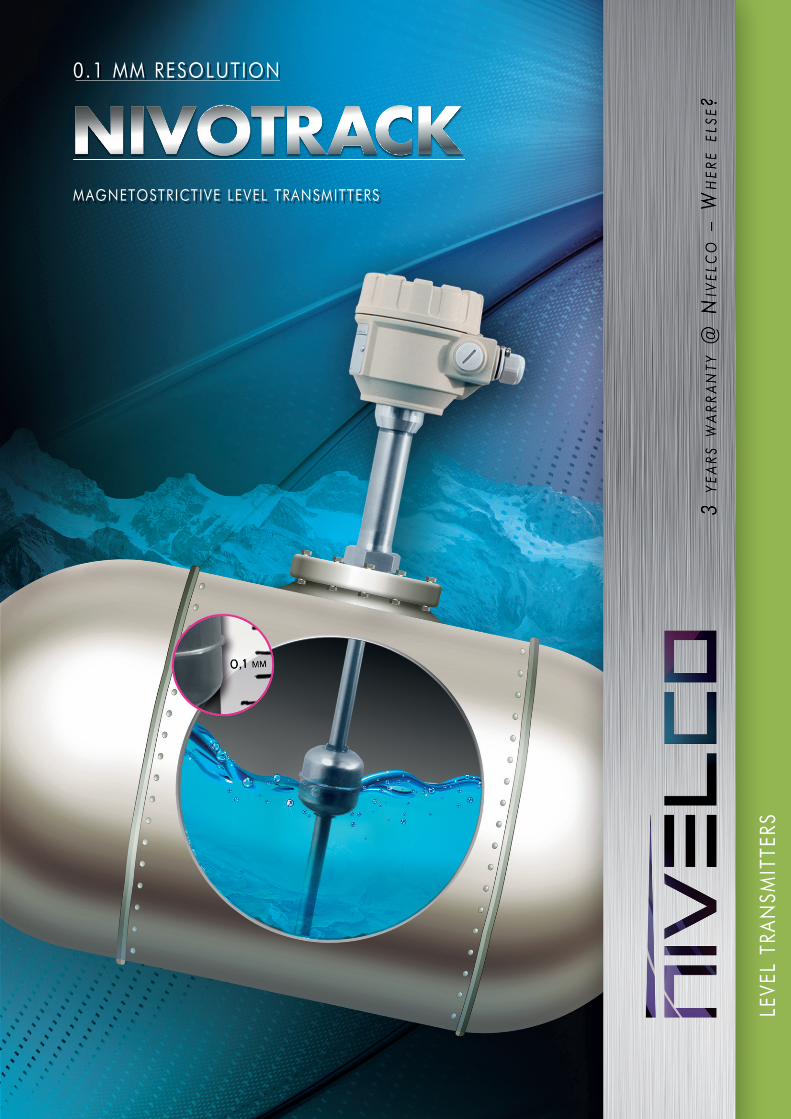
MAGNETOSTRICTIVE LEVEL TRANSMITTERS
LEVE
L TR
AN
SMIT
TERS
0 .1 MM RESOLUTION

NIVOTRACK MAGNETOSTRICTIVE LEVEL TRANSMITTERS
MAIN FEATURES APPLICATIONS ■ Custody transfer measurement ■ Oil and gas industry ■ Fuels and gasoline products ■ Pharmaceutical industry ■ Chemical industry ■ Food industry ■ Alcohols and beverages ■ Installation in bypass tubes feasible ■ Supplementary level transmitter for
NIVOFLIP magnetic flip indicator
■ 0.1 mm or 1 mm resolution ■ Insertion length maximum 15 m ■ Rigid or flexible guide tube ■ Plastic coated version for chemicals ■ 4-20 mA and HART output ■ Graphical display ■ 99 point linearization table ■ Measurement optimalisation ■ Volume measurement ■ Robbanásbiztos kivitel ■ Volume measurement ■ OIML R85 certification
GENERAL DESCRIPTIONNIVOTRACK magnetostrictive transmitters are an ideal solution for high accuracy measurement of clean fluids. Its high precision renders the NIVOTRACK suitable for custody transfer measurement of liquids such as fuels, solvents, alcohol derivatives etc. Units with flexible tube do not only make this accurate measurement for higher tanks possible, but offer a more convenient way for shipment and installation. Plastic coated versions of the NIVOTRACK substantially expand the field of application by a wide range of aggressive materials.Integrating the transmitter into a process control system is easy thanks to the intelligent signal processing and communication software as well as the wide of range of accessories offered.
OPERATING PRINCIPLEA float containing a magnetic disc moves along a guide tube with the specific magnetostrictive wire in it. A pulse generated by the electronics travels along the magnetostrictive wire. At the point the pulse reaches the float’s magnetic field, a torsion develops. Reflected from the torsion point, the pulse creates an acoustic wave that travels back along the wire. The 4-20 mA output of the transmitter is proportional to the elapsed time between the excitation and detection.
POSITION OF THE DISPLAYVertical and horizontal display position is offered for optimal mounting in your application.
„A” position „B” position
O U R P R O F E S S I O N
Current impulse
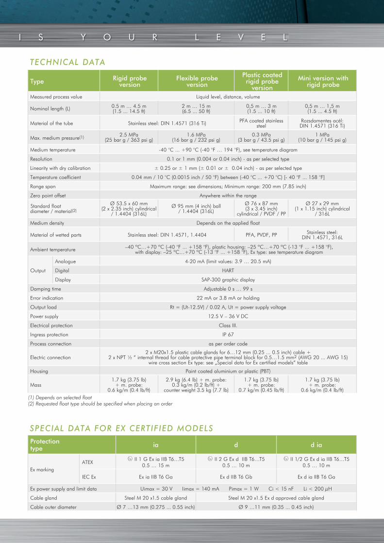
TECHNICAL DATA
SPECIAL DATA FOR EX CERTIFIED MODELS
(1) Depends on selected float(2) Requested float type should be specified when placing an order
Protectiontype ia d d ia
Ex markingATEX
II 1 G Ex ia IIB T6…T5 0.5 … 15 m
II 2 G Ex d IIB T6…T50.5 … 10 m
II 1/2 G Ex d ia IIB T6…T50.5 … 10 m
IEC Ex Ex ia IIB T6 Ga Ex d IIB T6 Gb Ex d ia IIB T6 Ga
Ex power supply and limit data Uimax = 30 V Iimax = 140 mA Pimax = 1 W Ci < 15 nF Li < 200 μH
Cable gland Steel M 20 x1.5 cable gland Steel M 20 x1.5 Ex d approved cable gland
Cable outer diameter Ø 7 …13 mm (0.275 ... 0.55 inch) Ø 9 …11 mm (0.35 ... 0.45 inch)
Type Rigid probeversion
Flexible probeversion
Plastic coated rigid probe
version
Mini version with rigid probe
Measured process value Liquid level, distance, volume
Nominal length (L) 0.5 m … 4.5 m(1.5 ... 14.5 ft)
2 m … 15 m(6.5 ... 50 ft)
0,5 m … 3 m(1.5 ... 10 ft)
0,5 m … 1,5 m(1.5 ... 4.5 ft)
Material of the tube Stainless steel: DIN 1.4571 (316 Ti) PFA coated stainless steel
Rozsdamentes acél:DIN 1.4571 (316 Ti)
Max. medium pressure(1) 2.5 MPa (25 bar g / 363 psi g)
1.6 MPa (16 bar g / 232 psi g)
0.3 MPa (3 bar g / 43.5 psi g)
1 MPa (10 bar g / 145 psi g)
Medium temperature -40 °C ... +90 °C (-40 °F … 194 °F), see temperature diagram
Resolution 0.1 or 1 mm (0.004 or 0.04 inch) - as per selected type
Linearity with dry calibration ± 0.25 or ± 1 mm (± 0.01 or ± 0.04 inch) - as per selected type
Temperature coefficient 0.04 mm / 10 °C (0.0015 inch / 50 °F) between (-40 °C ... +70 °C) [- 40 °F ... 158 °F]
Range span Maximum range: see dimensions; Minimum range: 200 mm (7.85 inch)
Zero point offset Anywhere within the range
Standard floatdiameter / material(2)
Ø 53.5 x 60 mm (2 x 2.35 inch) cylindrical
/ 1.4404 (316L)
Ø 95 mm (4 inch) ball / 1.4404 (316L)
Ø 76 x 87 mm (3 x 3.45 inch)
cylindrical / PVDF / PP
Ø 27 x 29 mm (1 x 1.15 inch) cylindrical
/ 316L
Medium density Depends on the applied float
Material of wetted parts Stainless steel: DIN 1.4571, 1.4404 PFA, PVDF, PP Stainless steel: DIN 1.4571, 316L
Ambient temperature –40 ºC…+70 ºC (-40 °F ... +158 °F), plastic housing: –25 ºC…+70 ºC (-13 °F ... +158 °F), with display: –25 ºC…+70 ºC (-13 °F ... +158 °F), Ex type: see temperature diagram
Output
Analogue 4-20 mA (limit values: 3.9 … 20.5 mA)
Digital HART
Display SAP-300 graphic display
Damping time Adjustable 0 s … 99 s
Error indication 22 mA or 3.8 mA or holding
Output load Rt = (Ut-12.5V) / 0.02 A, Ut = power supply voltage
Power supply 12.5 V – 36 V DC
Electrical protection Class III.
Ingress protection IP 67
Process connection as per order code
Electric connection2 x M20x1.5 plastic cable glands for 6…12 mm (0.25 ... 0.5 inch) cable +
2 x NPT ½ ” internal thread for cable protective pipe terminal block for 0.5…1.5 mm2 (AWG 20 ... AWG 15) wire cross section Ex type: see „Special data for Ex certified models” table
Housing Paint coated aluminium or plastic (PBT)
Mass1.7 kg (3.75 lb)
+ m. probe: 0.6 kg/m (0.4 lb/ft)
2.9 kg (6.4 lb) + m. probe: 0.3 kg/m (0.2 lb/ft) +
counter weight 3.5 kg (7.7 lb)
1.7 kg (3.75 lb)+ m. probe:
0.7 kg/m (0.45 lb/ft)
1.7 kg (3.75 lb)+ m. probe:
0.6 kg/m (0.4 lb/ft)
I S Y O U R L E V E L
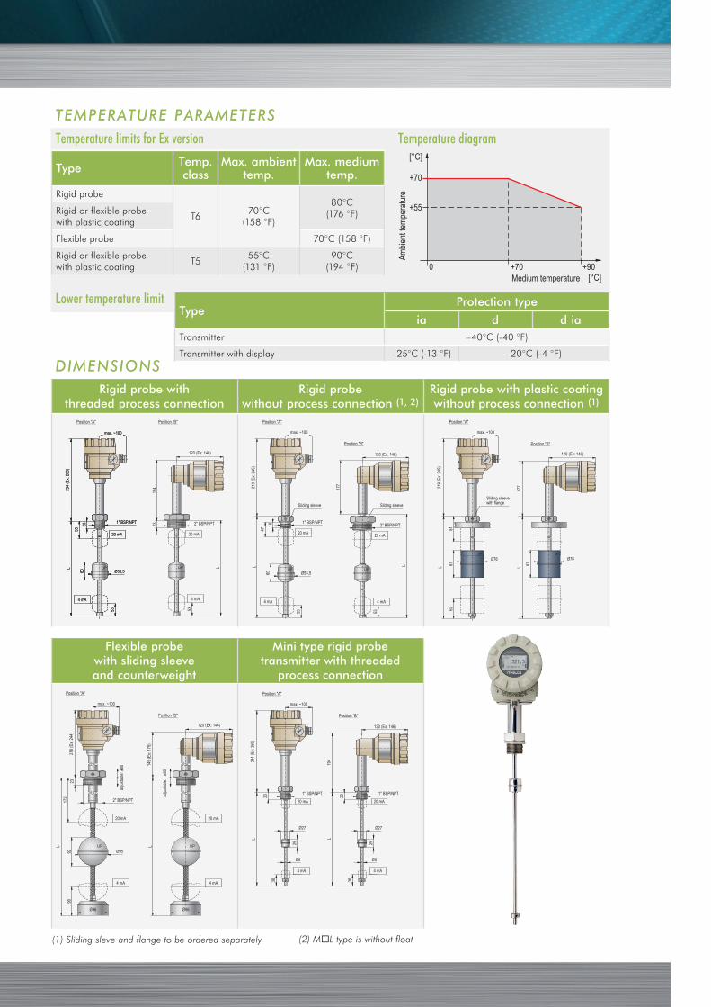
Temperature limits for Ex version Temperature diagram
TEMPERATURE PARAMETERS
Type Temp.class
Max. ambient temp.
Max. mediumtemp.
Rigid probe
T670°C
(158 °F)
80°C(176 °F)Rigid or flexible probe
with plastic coating
Flexible probe 70°C (158 °F)
Rigid or flexible probewith plastic coating
T555°C
(131 °F)90°C
(194 °F)
Lower temperature limit
Rigid probe withthreaded process connection
Rigid probewithout process connection (1, 2)
Rigid probe with plastic coatingwithout process connection (1)
Flexible probewith sliding sleeveand counterweight
Mini type rigid probetransmitter with threaded
process connection
(1) Sliding sleve and flange to be ordered separately (2) ML type is without float
TypeProtection type
ia d d iaTransmitter –40°C (-40 °F)
Transmitter with display –25°C (-13 °F) –20°C (-4 °F)
DIMENSIONS
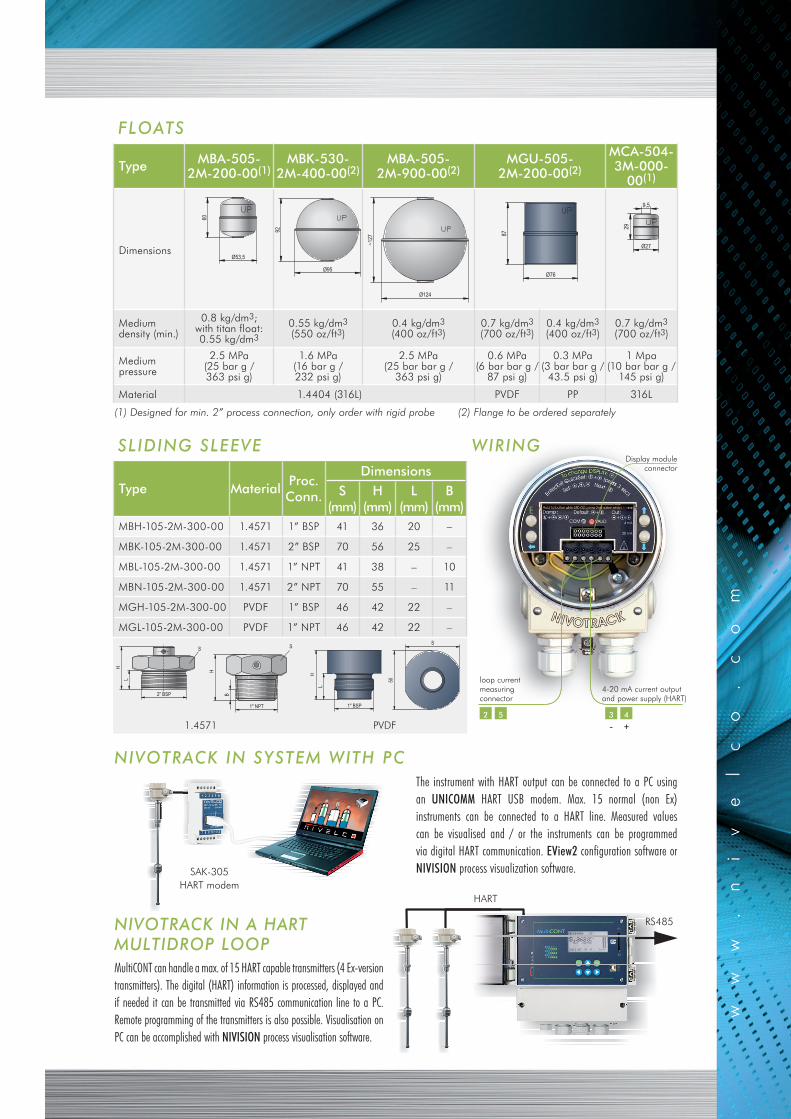
FLOATS
Type MBA-505-2M-200-00(1)
MBK-530-2M-400-00(2)
MBA-505-2M-900-00(2)
MGU-505-2M-200-00(2)
MCA-504-3M-000-
00(1)
Dimensions
Medium density (min.)
0.8 kg/dm3;with titan float: 0.55 kg/dm3
0.55 kg/dm3
(550 oz/ft3)0.4 kg/dm3
(400 oz/ft3)0.7 kg/dm3
(700 oz/ft3)0.4 kg/dm3
(400 oz/ft3)0.7 kg/dm3
(700 oz/ft3)
Mediumpressure
2.5 MPa (25 bar g / 363 psi g)
1.6 MPa (16 bar g / 232 psi g)
2.5 MPa (25 bar bar g /
363 psi g)
0.6 MPa (6 bar bar g /
87 psi g)
0.3 MPa (3 bar bar g /
43.5 psi g)
1 Mpa (10 bar bar g /
145 psi g)
Material 1.4404 (316L) PVDF PP 316L
(1) Designed for min. 2” process connection, only order with rigid probe (2) Flange to be ordered separately
MultiCONT can handle a max. of 15 HART capable transmitters (4 Ex-version transmitters). The digital (HART) information is processed, displayed and if needed it can be transmitted via RS485 communication line to a PC. Remote programming of the transmitters is also possible. Visualisation on PC can be accomplished with NIVISION process visualisation software.
RS485
HART
The instrument with HART output can be connected to a PC using an UNICOMM HART USB modem. Max. 15 normal (non Ex) instruments can be connected to a HART line. Measured values can be visualised and / or the instruments can be programmed via digital HART communication. EView2 configuration software or NIVISION process visualization software.
NIVOTRACK IN SYSTEM WITH PC
NIVOTRACK IN A HARTMULTIDROP LOOP
SAK-305HART modem
WIRING
loop current measuring connector
2 5 3 4
-
Display moduleconnector
4-20 mA current output and power supply (HART)
SLIDING SLEEVE
Type MaterialProc.Conn.
DimensionsS
(mm)H
(mm)L
(mm)B
(mm)MBH-105-2M-300-00 1.4571 1” BSP 41 36 20 –
MBK-105-2M-300-00 1.4571 2” BSP 70 56 25 –
MBL-105-2M-300-00 1.4571 1” NPT 41 38 – 10
MBN-105-2M-300-00 1.4571 2” NPT 70 55 – 11
MGH-105-2M-300-00 PVDF 1” BSP 46 42 22 –
MGL-105-2M-300-00 PVDF 1” NPT 46 42 22 –
1.4571 PVDF +

mt5
0s13
a060
4b
Nive
lco re
serv
es th
e righ
t to c
hang
e tec
hnica
l data
with
out n
otice
!
ORDER CODES (NOT ALL COMBINAT ION AVAL IABLE)NIVOTRACK magnetostrictive level transmitters
Output / Resolution / Ex Code
4-20 mA / 0.1 mm 1
4-20 mA / 1 mm 2
4-20 mA + HART / 0.1 mm 3
4-20 mA + HART / 1 mm 4
4-20 mA / 0.1 mm / Ex ia 5
4-20 mA / 1 mm / Ex ia 6
4-20 mA + HART / 0.1 mm / Ex ia 7
4-20 mA + HART / 1 mm / Ex ia 8
4-20 mA / 0.1 mm / Ex d (6) A
4-20 mA + HART / 0.1 mm / Ex d (6) B
4-20 mA / 0.1 mm / Ex d+Ex ia (6) C
4-20 mA + HART / 0.1 mm / Ex d+Ex ia (6) D
Probe type /Process connection Code
Rigid / 1” BSP A
Rigid / 2” BSP C
Rigid / 1” NPT D
Rigid / 2” NPT G
Rigid / w/o process conn.(4) U
Rigid / for NIVOFLIP,w/o process conn. & float L
Flexible / 2“ BSP K
Flexible / 2“ NPT N
Flexible / w/o process conn.(5) Z
NIVOTRACK M – –(1)
Type Code
Transmitter T
Transmitter + display(2) B
Transmitter withplastic coated probe E
Transmitter + display with plastic coated probe(2) G
Transmitter mini(7) M
Transmitter mini + display(7) C
Housing Code
Aluminium 5
Plastic(3) 6
(1) The order code of an Ex version should end in „Ex”(2) The position of the display (A or B) should be specified in the order(3) Not available in Ex version(4) Threaded sliding sleeve should be ordered separately(5) Sliding sleeve with flange should be ordered separately(6) Insertion length max. 10 m(7) Insertion length max. 1.5 m
ACCESSORIESFlanges
Pressure Code
PN16 / 150 psi 1
PN25 / 300 psi 2
Instr. connection Code
1” BSP 2
2” BSP 3
1” NPT 5
2” NPT 6
Sliding sleeve A(8)
MFT –
Standard / Material Code
DIN / A38 1
DIN / 1.4571 2
DIN / PP 3
DIN / A38 +, PTFE 4
ANSI / A38 5
ANSI / 1.4571 6
ANSI / PP 7
ANSI / A38 +, PTFE 8
Type Process connection
MBH-105-2M-300-00 1” BSP
MBK-105-2M-300-00 2” BSP
MBL-105-2M-300-00 1” NPT
MBN-105-2M-300-00 2” NPT
MGH-105-2M-300-00 1” BSP / PVDF, for plastic coated version
MGL-105-2M-300-00 1” NPT / PVDF, for plastic coated version
SizeCode
DIN ANSI
DN50 2” 0
DN65 2 1/2” 1
DN80 3” 2
DN100 4” 3
DN125 5” 4
DN150 6” 5
DN200 8” 6
Threaded sliding sleeve
Floats
Type Diameter / Material
MBA-505-2M-200-00 Ø 53.5 mm / 1.4571
MBA-505-2M-800-00 Ø 53.5 mm / Titan
MBK-530-2M-400-00 Ø 95 mm / 1.4571
MGU-505-2M-200-00 Ø 76 mm / PVDF / PP
MBA-505-2M-900-00 Ø 124 mm / 1.4571
MCA-504-3M-000-00 Ø 27 mm / 316L
Other accessories
Type Description
SAP-300 Plug-in display module
SAT-304 / SAK-305 HART-USB / RS485 modem
SAS-303 EView2 software
Code Probe length Code
0 0 m 0 m 0
1 1 m 0.1 m 1
2 2 m 0.2 m 2•••
•••
•••
•••
9 9 m 0.9 m 9
A 10 m
B 11 m
C 12 m
D 13 m
E 14 m
F 15 m
(8) Only for MZ types
Specifi
cation
s in m
etric &
US un
its!
N I V E L C O P R O C E S S C O N T R O L C O .H - 1 0 4 3 B U D A P E S T , D U G O N I C S U . 1 1.TEL. : (36-1 ) 889-0100 ▪ FAX: (36-1) 889-0200 E-mail : [email protected] http:/ /www.nivelco.com