01 Construction Code of Practice - Method of Statement
32
1 | Page CODE OF PRACTICE Method Statement National Polytechnic Institute of Cambodia Project Detailed procedure of Namcong’s post -tensioning construction Construction
-
Upload
sopheap-chek -
Category
Documents
-
view
490 -
download
1
Transcript of 01 Construction Code of Practice - Method of Statement
1 | P a g e
CODE OF PRACTICE Method Statement
National Polytechnic Institute of Cambodia Project
Detailed procedure of Namcong’s post-tensioning construction
Construction

2 | P a g e
Submission | National Polytechnic
Institute of Cambodia Prepared by Namcong www.namcong.com.kh
3 | P a g e
B
A
0 First submission
Revision Date Description Prepared Approved
PROJECT
NATIONAL POLYTECHNIC
INSTITUTE CAMBODIA
ADDRESS
PHNOM PENH - CAMBODIA
TITLE:
CODE OF PRACTICE POST-TENSIONING METHOD OF STATEMENT
DOCUMENT N°
02-PT/NPIC/NCC
Prepared Checked Date
Checked Checked Approved
NAMCONG ENGINEERING CORPORATION
Our Offices:
Ho Chi Minh:
Add.: R.3-S5, 3nd Fl., No. 31-33 Phan Huy Ich Str., Ward 15, Tan Binh Dist., Ho Chi Minh City, Vietnam.
Da Nang:
Add.: 3th Fl., No. 4 - 6 Tran Nhan Tong Str., Tho Quang Ward, Son Tra Dist., Da Nang City, Vietnam.
Hanoi:
Add.: Room 706, 7th Fl, Kim Anh Building, A2A Duy Tan Street, Dich Vong Hau Ward, Cau Giay Dist., Hanoi
City, Vietnam.
Phnom Penh:
Add.: Room 4D - No. 148ABC- Street 63, Sangkat Chaktomok, Khan Doun Penh, Phnom Penh, Cambodia
In case Namcong does not receive any official response from Main Contractor / Consultant /
Client in within 7 working days from submission date, this method statement is considered as
approved by all relevant patties involve to this project.

4 | P a g e
COMPANY
APPROVAL
THE OWNER
CONSULTANT
MAIN CONTRACTOR
5 | P a g e
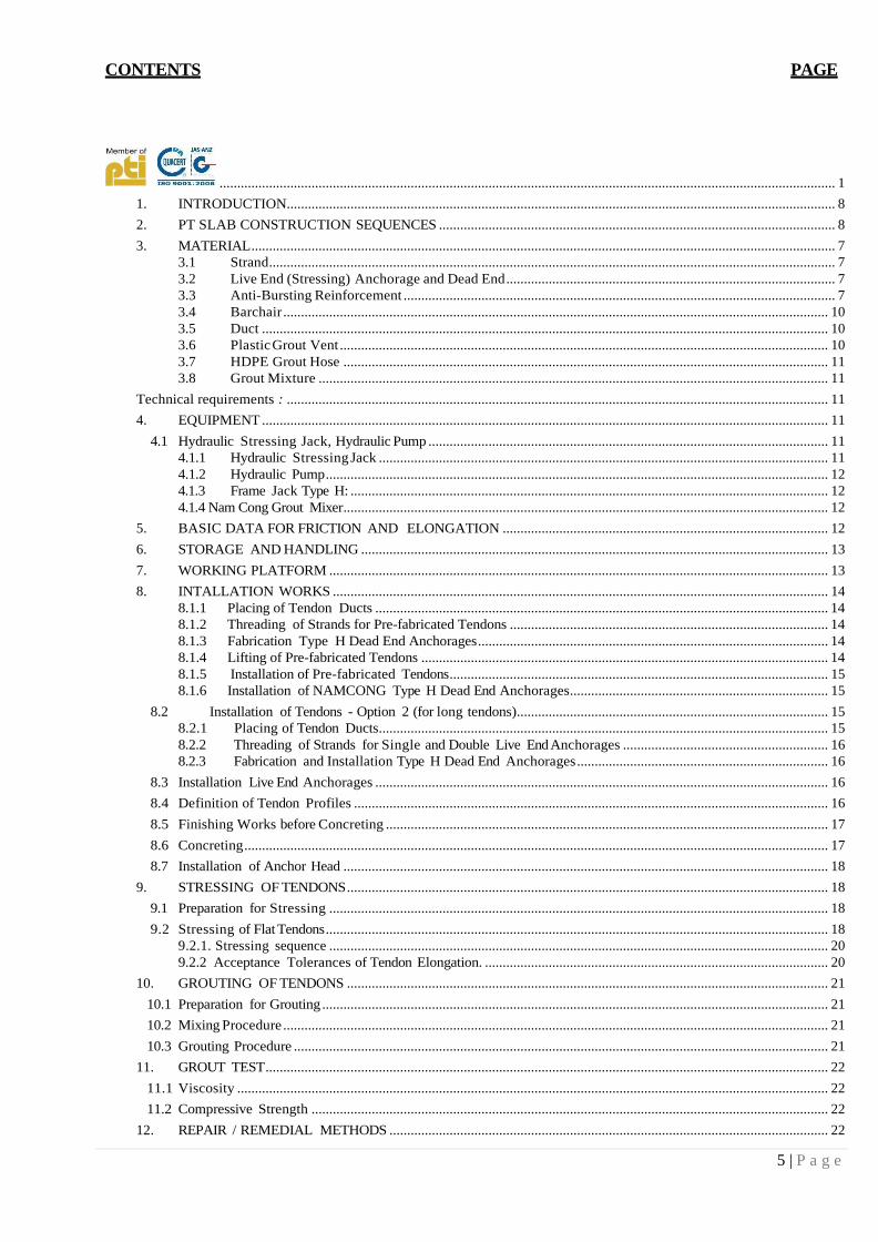
CONTENTS PAGE
.............................................................................................................................................................................. 1
1. INTRODUCTION........................................................................................................................................................... 8
2. PT SLAB CONSTRUCTION SEQUENCES ................................................................................................................ 8
3. MATERIAL ..................................................................................................................................................................... 7 3.1 Strand ................................................................................................................................................................ 7 3.2 Live End (Stressing) Anchorage and Dead End ............................................................................................. 7 3.3 Anti-Bursting Reinforcement .......................................................................................................................... 7 3.4 Barchair .......................................................................................................................................................... 10 3.5 Duct ................................................................................................................................................................ 10 3.6 Plastic Grout Vent .......................................................................................................................................... 10 3.7 HDPE Grout Hose ......................................................................................................................................... 11 3.8 Grout Mixture ................................................................................................................................................ 11
Technical requirements : ......................................................................................................................................................... 11
4. EQUIPMENT ................................................................................................................................................................ 11
4.1 Hydraulic Stressing Jack, Hydraulic Pump ................................................................................................................. 11 4.1.1 Hydraulic Stressing Jack ............................................................................................................................... 11 4.1.2 Hydraulic Pump .............................................................................................................................................. 12 4.1.3 Frame Jack Type H: ....................................................................................................................................... 12 4.1.4 Nam Cong Grout Mixer ......................................................................................................................................... 12
5. BASIC DATA FOR FRICTION AND ELONGATION ............................................................................................ 12
6. STORAGE AND HANDLING .................................................................................................................................... 13
7. WORKING PLATFORM ............................................................................................................................................. 13
8. INTALLATION WORKS ............................................................................................................................................ 14 8.1.1 Placing of Tendon Ducts ................................................................................................................................ 14
8.1.2 Threading of Strands for Pre-fabricated Tendons .......................................................................................... 14
8.1.3 Fabrication Type H Dead End Anchorages ................................................................................................... 14
8.1.4 Lifting of Pre-fabricated Tendons ................................................................................................................... 14
8.1.5 Installation of Pre-fabricated Tendons ........................................................................................................... 15 8.1.6 Installation of NAMCONG Type H Dead End Anchorages......................................................................... 15
8.2 Installation of Tendons - Option 2 (for long tendons) ........................................................................................ 15 8.2.1 Placing of Tendon Ducts ............................................................................................................................... 15 8.2.2 Threading of Strands for Single and Double Live End Anchorages .......................................................... 16 8.2.3 Fabrication and Installation Type H Dead End Anchorages ....................................................................... 16
8.3 Installation Live End Anchorages ................................................................................................................................ 16
8.4 Definition of Tendon Profiles ...................................................................................................................................... 16
8.5 Finishing Works before Concreting ............................................................................................................................. 17
8.6 Concreting ..................................................................................................................................................................... 17
8.7 Installation of Anchor Head ......................................................................................................................................... 18
9. STRESSING OF TENDONS ........................................................................................................................................ 18
9.1 Preparation for Stressing ............................................................................................................................................. 18
9.2 Stressing of Flat Tendons .............................................................................................................................................. 18 9.2.1. Stressing sequence ............................................................................................................................................. 20 9.2.2 Acceptance Tolerances of Tendon Elongation. ................................................................................................. 20
10. GROUTING OF TENDONS ........................................................................................................................................ 21
10.1 Preparation for Grouting ............................................................................................................................................... 21
10.2 Mixing Procedure .......................................................................................................................................................... 21
10.3 Grouting Procedure ....................................................................................................................................................... 21
11. GROUT TEST ............................................................................................................................................................... 22
11.1 Viscosity ....................................................................................................................................................................... 22
11.2 Compressive Strength .................................................................................................................................................. 22
12. REPAIR / REMEDIAL METHODS ............................................................................................................................ 22
6 | P a g e
12.1 Installation & pouring concrete problems .................................................................................................................... 22
12.2 Stressing problem: Broken strand, slippage strand… ................................................................................................. 22
12.3 Grouting problem: stuck at grout hose, tendon blocked… ......................................................................................... 23
13. SPECIFIC SAFETY REQUIREMENTS & PRECAUTION MEASURES .............................................................. 23
13.1 General requirement ...................................................................................................................................................... 23
13.2 Lifting of Material and Equipment ............................................................................................................................... 23
13.3 PT Tendon Installation .................................................................................................................................................. 23
13.4 PT Tendon Stressing .................................................................................................................................................... 23
13.5 Grouting ...................................................................................................................................................................... 24
14. EQUIPMENT & MANPOWER LIST ........................................................................................................................ 24
15. ORGANISATION CHART .......................................................................................................................................... 24
16. APPENDIX A: PARTICULARS FOR GROUT MIX ............................................................................................... 25
16.1 Technical Data for Holcim Cement PCB 40 ........................................................................................................... 25
16.2 Technical Data for Grout Additive Sikament NN ................................................................................................... 26
17. APPENDIX B: CARE OF DUCTS AND TENDONS DURING CONCRETING .................................................. 28
18. APPENDIX C – SAMPLE WORKING PLATFORM ............................................................................................... 29
19. APPENDIX D - EQUIPMENT LIST .......................................................................................................................... 33
20. APPENDIX E – MANPOWER LIST ......................................................................................................................... 34
Construction Code of Practice / Method Statement
Construction Submission | NPIC – Phnom Penh
1. INTRODUCTION
This Method Statement describes Namcong’s post-tensioning operations, namely tendon installation, stressing
and grouting of the tendons, for the project National Polytechnic Institute Cambodia at Phnom Penh -
Cambodia.
The construction procedure shall follow the description shown on this method statement and the shop drawings.
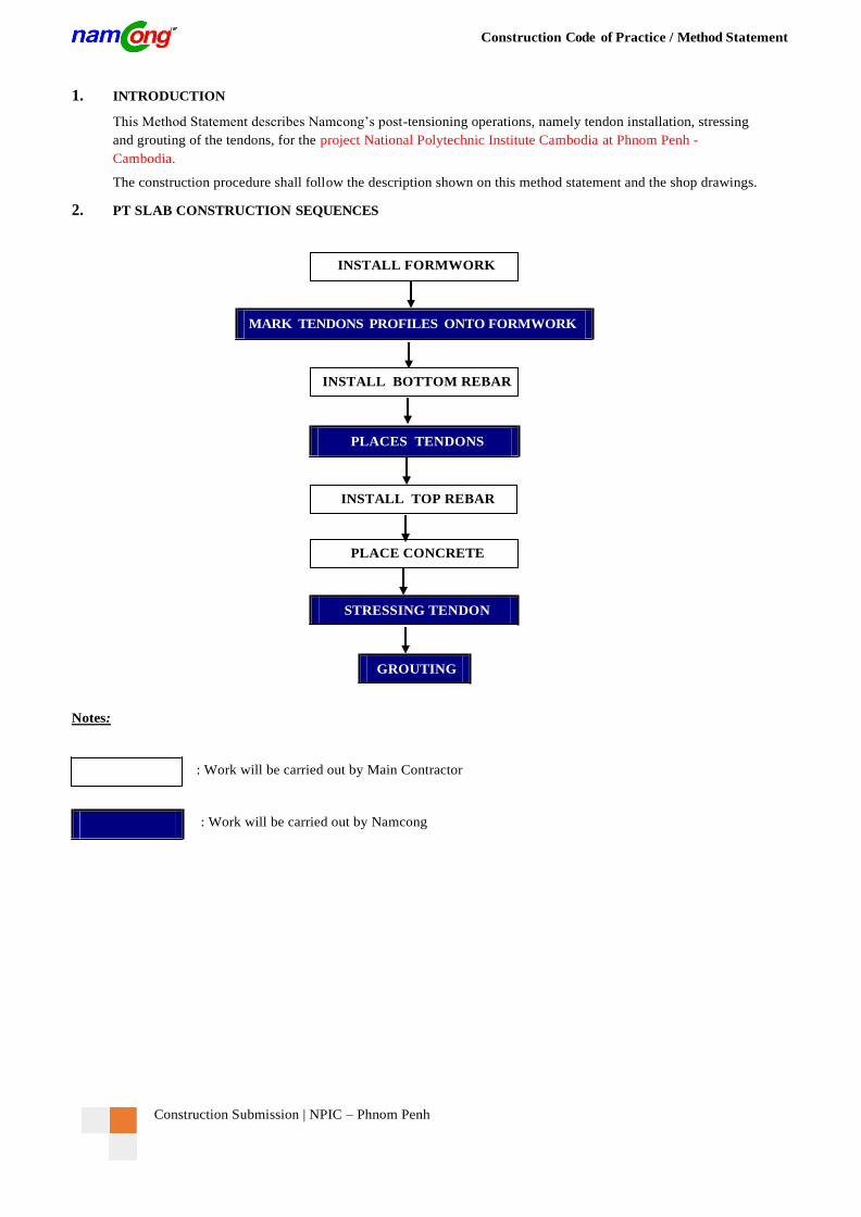
2. PT SLAB CONSTRUCTION SEQUENCES
Notes:
: Work will be carried out by Main Contractor
: Work will be carried out by Namcong
STRESSING TENDON
GROUTING
INSTALL FORMWORK
PLACE CONCRETE
MARK TENDONS PROFILES ONTO FORMWORK
INSTALL BOTTOM REBAR
PLACES TENDONS
INSTALL TOP REBAR
Construction Code of Practice / Method Statement
Construction Submission | NPIC – Phnom Penh
3. MATERIAL
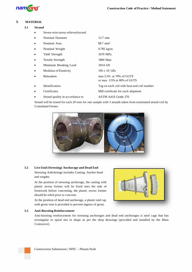
3.1 Strand
Seven-wire stress-relieved strand
Nominal Diameter 12.7 mm
Nominal Area 98.7 mm2
Nominal Weight 0.785 kg/m
Yield Strength 1670 MPa
Tensile Strength 1860 Mpa
Minimum Breaking Load 183.6 kN
Modulus of Elasticity 195 ± 10 GPa
Relaxation max 2.5% at 70% of GUTS
or max 3.5% at 80% of GUTS
Identification Tag on each coil with heat and coil number
Certificates Mill certificate for each shipment
Strand quality in accordance to ASTM A416 Grade 270
Strand will be tested for each 20 tons for one sample with 3 strands taken from nominated strand coil by
Consultant/Owner.
3.2 Live End (Stressing) Anchorage and Dead End
Stressing Anhchorage includes Casting, Anchor head
and wegdes
At the position of stressing anchorage, the casting with
plastic recess former will be fixed onto the side of
formwork before concreting, the plastic recess former
should be oiled prior to concrete.
At the position of dead end anchorage, a plastic end cap
with grout vent is provided to prevent ingress of grout.
3.3 Anti-Bursting Reinforcement
Anti-bursting reinforcement for stressing anchorages and dead end anchorages is steel cage that has
rectangular or spiral ties in shape as per the shop drawings (provided and installed by the Main
Contractor).

Construction Submission | NPIC – Phnom Penh
Construction Code of Practice / Method Statement
3.4 Barchair
The tendon profile is achieved by
using barchair supported at 800 mm
up to 1000 mm intervals to the
underside of the tendon unless
noted otherwise.
Bar chairs with height varies should
be made by steel like strand. The
bottom part of the steel bar chair is
painted for corrosion protection.
At beam location, tendons can be normally supported on horizontal bars (supplied by MC) fixed to
stirrups or suspended to the top reinforcement with tie wire where appropriate.
At the highest and lowest points, the tendon can be fixed to top and bottom layer of rebar to achieve their
profile without bar chair.
3.5 Duct
The sheathing consists of corrugated spiral type ducts made from galvanized steel strip width by 0.23 -
0.30 mm thickness.
Plastic/Steel duct coupler is provided at the end of every duct for intermediate connection. Coupler should
be properly sealed with tape to avoid ingress of grout. The duct coupler consists of the larger dimension
of duct so that the regular duct can be passed through the coupler. Length of coupler is usually 150-200
mm.
3.6 Plastic Grout Vent
Intermediate plastic grout vents are provided at highest points along the tendon allowing water and air
to flow outside. NC recommends avoiding installing grout vents at lowest points since the outlet here is
difficult to seal and may cause blockage. A distance between vents varies with duct type and size, tendon
profile, grouting procedures and equipment used, normally 30m of maximum is applied.
A hole is drilled/cut through the top surface of the duct at each vent location for the passage of the grout
from the duct through the vent. The plastic vent is fixed by tie wire and sealed using tape.

Construction Submission | NPIC – Phnom Penh
Construction Code of Practice / Method Statement
3.7 HDPE Grout Hose
HDPE grout hose with 14mm ID is provided
at all casting inlets and at the outlets of the end
caps for dead end anchorages and all
intermediate grout vents where water and air
can accumulate. Vent hose should be
extended 300mm outside the concrete surface
for future grouting and sealing.
In case the grout vent is located at the column
or core wall position, the HDPE grout hose
should be so aligned such that the hose outlet
can be avoided from damages due to
formwork erection.
3.8 Grout Mixture
The grout mixture consists of:
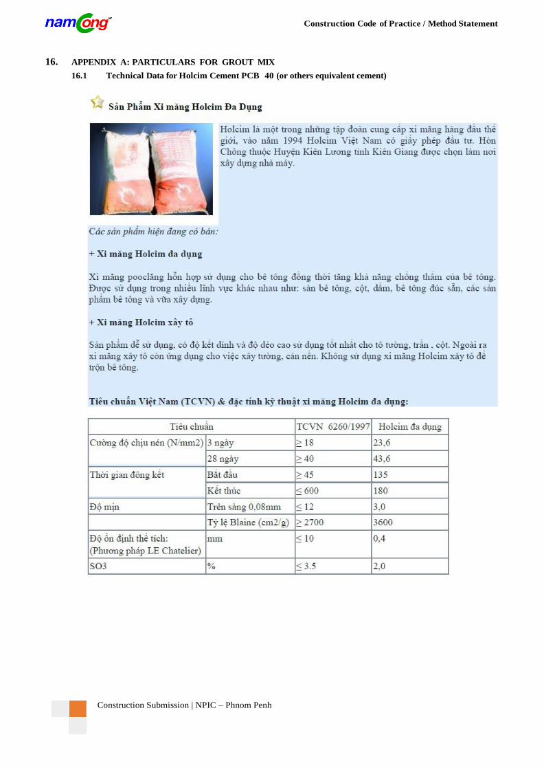
Portland Cement PCB-40 in 50 kg bag - Holcim (or others equivalent cement)
Potable Water
Grout Additive Expanfluid or Sika Intraplast Z-HV
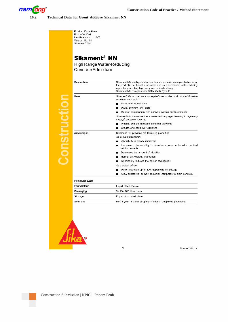
Grout Additive Sikament NN
Grout mix trials should be performed prior to grouting of tendons in order to establish the most suitable
mix.
Proposed grout mix proportion:
Cement Water Sika Intraplast
Z-HV Sikament NN
100kg 34 lit 0.6 kg 1.0 lit
Technical requirements :
Viscosity ≤ 25 sec.
Compressive cube strength shall be not less than 30 N/mm2 at 28 days or 27 N/ mm2 at 7 days if it is
proposed to estimate the likely 28 day strength at 7 days. (BS EN 447-2007)
Temperature 50C ÷ 350C
Mixing time min. 4 minutes
For more information on additive type, please refer to “PARTICULARS FOR GROUT MIX” in Appendix A.
4. EQUIPMENT
4.1 Hydraulic Stressing Jack, Hydraulic Pump
4.1.1. Hydraulic Stressing Jack
Hydraulic Stressing Jacks are used to stressing tendons. The calibration certificate of hydraulic
stressing jacks must be valid prior to construction.
Hydraulic Stressing Jacks for Flat Duct / Capacity: 256 k N.
Construction Submission | NPIC – Phnom Penh
Construction Code of Practice / Method Statement
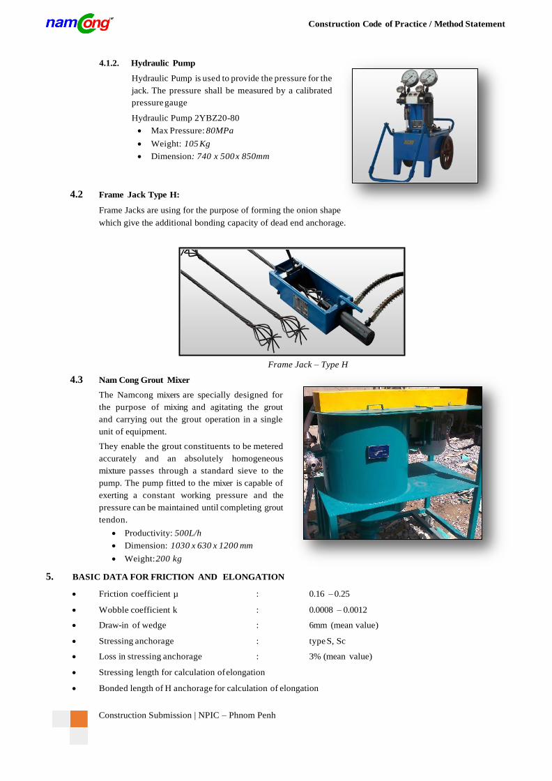
4.1.2. Hydraulic Pump
Hydraulic Pump is used to provide the pressure for the
jack. The pressure shall be measured by a calibrated
pressure gauge
Hydraulic Pump 2YBZ20-80
Max Pressure: 80MPa
Weight: 105 Kg
Dimension: 740 x 500 x 850mm
4.2 Frame Jack Type H:
Frame Jacks are using for the purpose of forming the onion shape
which give the additional bonding capacity of dead end anchorage.
4.3 Nam Cong Grout Mixer
Frame Jack – Type H
The Namcong mixers are specially designed for
the purpose of mixing and agitating the grout
and carrying out the grout operation in a single
unit of equipment.
They enable the grout constituents to be metered
accurately and an absolutely homogeneous
mixture passes through a standard sieve to the
pump. The pump fitted to the mixer is capable of
exerting a constant working pressure and the
pressure can be maintained until completing grout
tendon.
Productivity: 500L/h
Dimension: 1030 x 630 x 1200 mm
Weight: 200 kg
5. BASIC DATA FOR FRICTION AND ELONGATION
Friction coefficient µ : 0.16 – 0.25
Wobble coefficient k : 0.0008 – 0.0012
Draw-in of wedge : 6mm (mean value)
Stressing anchorage : type S, Sc
Loss in stressing anchorage : 3% (mean value)
Stressing length for calculation of elongation
Bonded length of H anchorage for calculation of elongation
Construction Submission | NPIC – Phnom Penh
Construction Code of Practice / Method Statement
6. STORAGE AND HANDLING
(Items marked “by MC” should be done by the Main Contractor)
A storage yard should be prepared in advance and sufficient enough to accommodate all the required material
for the project. Ideally, the storage yard should be able to prevent the stored material from damage, vandalism,
heat causing deformation of plastic elements and moisture induced rusting process of steel components.
(by MC)
Unloading, storing and transportation operations inside the site should be the responsibility of Namcong with
tower crane or mobile crane, forklift, elevator, covered and secure storage area and storage facilities should be
supplied by the Main Contractor. (by MC, Namcong)
All material should be stored off the ground (with underlay, e.g. timber), covered and not exposed to the weather.
(by Namcong)
Wedges and anchor heads should be stored in a room or container whereas for the other material, a temporary
cover is adequate. (by Namcong)
All materials should be periodically examined, say at 10 monthly intervals or anytime if required.
(by MC, Namcong)
Care should be taken during handling to avoid mechanical damages. (by Namcong)
These main elements are to be considered when setting up a storage yard capacity:
Strand coil
Duct
Casting
Anchor head
Wedge
Materials for grouting (cement, Sika Intraplast Z-HV, Sika NN)
Other material (plastic production, mastic, tape...)
Equipment (pushing machine, stressing jack, hydraulic pump, grouting mixer, frame jack...)
Hand tools and other temporary equipment.
7. WORKING PLATFORM
(Items marked “by MC” should be done by the Main Contractor)
A safety working platform system is needed for installation (casting installation, threading strands...), stressing
and grouting works. (by MC)
The installation, stressing and grouting works of tendons are to be done from a working platform. (by MC)
The working platform should be able to carry the load of working personnel and equipment (approx. 300
kg). (by MC)

Construction Submission | NPIC – Phnom Penh
Construction Code of Practice / Method Statement
8. INTALLATION WORKS
(Items marked “by MC” should be done by the Main Contractor)
There are three options of tendons installation on site as following:
Option 1: Pre-fabricated tendons on ground before lifting to installation position.
Option 2: Pre-cut strand on ground and form the onion dead end before lifting to installation position.
Option 3: Install tendons directly from strand coils to installation position.
In this project, due to height, Namcong proposes to use option 1 or 2 for easier, quicker and safer. However, we
still show the option 3 as reference.
8.1 Installation of Tendons - Option 1 (For short Tendon)
8.1.1 Placing of Tendon Ducts
The tendon ducts are placed on the ground by manpower and connected with plastic duct couplers
to meet the required length as per the shop drawing. (by Namcong)
8.1.2 Threading of Strands for Pre-fabricated Tendons
Each tendon should be formed by strands from the same batch as far as practical.
(by Namcong)
The strands should be pulled from strand coils and threaded one by one into the tendon duct by
means of manpower and/or pushing machine on the ground. (by Namcong)
Cut the strand when its length meets required length (including stressing length). It is not allowed
to cut the strands by oxy-acetylene fire or equivalent heating method. Disk cutting machine is
recommended. (by Namcong)
8.1.3 Fabrication Type H Dead End Anchorages
Type H dead end anchorage should be used for every tendon with single live end anchorage unless
noted otherwise.
Fabrication type H dead end anchorage should be done as soon as the tendon duct is installed and
the strands are threaded. (by Namcong)
At the position of dead end anchorage, a plastic end cap with grout vent is provided to prevent
ingress of grout. (by Namcong)
Form the onion shape at the dead end using H frame jack. (by Namcong)
8.1.4 Lifting of Pre-fabricated Tendons
After threading of strands, the pre-fabricated tendons should be lifted to installation position by
using special lifting frame with the help of tower crane supplied by the Main Contractor.
(by MC, Namcong)
Loading the pre-fabricated tendons to the lifting frame by means of manpower making sure that
tendons are not damaged during lift ing operations. (by Namcong)
Lift up the lifting frame with pre-fabricated tendons slowly to the installation position. (by MC)
Unload the pre-fabricated tendons to the installation position by means of manpower.
(by Namcong)
Construction Submission | NPIC – Phnom Penh
Construction Code of Practice / Method Statement
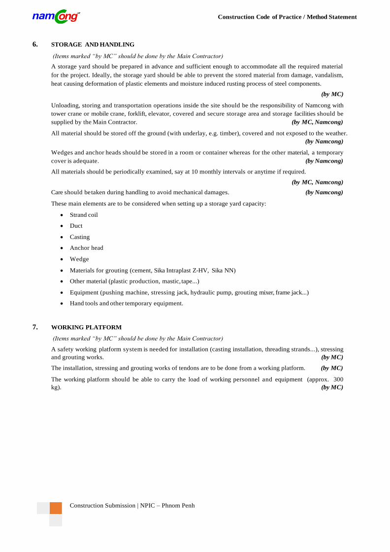
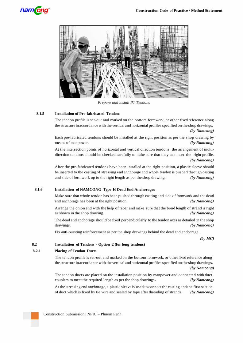
Prepare and install PT Tendons
8.1.5 Installation of Pre-fabricated Tendons
The tendon profile is set-out and marked on the bottom formwork, or other fixed reference along
the structure in accordance with the vertical and horizontal profiles specified on the shop drawings.
(by Namcong)
Each pre-fabricated tendons should be installed at the right position as per the shop drawing by
means of manpower. (by Namcong)
At the intersection points of horizontal and vertical direction tendons, the arrangement of multi-
direction tendons should be checked carefully to make sure that they can meet the right profile.
(by Namcong)
After the pre-fabricated tendons have been installed at the right position, a plastic sleeve should
be inserted to the casting of stressing end anchorage and whole tendon is pushed through casting
and side of formwork up to the right length as per the shop drawing. (by Namcong)
8.1.6 Installation of NAMCONG Type H Dead End Anchorages
Make sure that whole tendon has been pushed through casting and side of formwork and the dead
end anchorage has been at the right position. (by Namcong)
Arrange the onion end with the help of rebar and make sure that the bond length of strand is right
as shown in the shop drawing. (by Namcong)
The dead end anchorage should be fixed perpendicularly to the tendon axes as detailed in the shop
drawings. (by Namcong)
Fix anti-bursting reinforcement as per the shop drawings behind the dead end anchorage.
(by MC)
8.2 Installation of Tendons - Option 2 (for long tendons)
8.2.1 Placing of Tendon Ducts
The tendon profile is set-out and marked on the bottom formwork, or other fixed reference along
the structure in accordance with the vertical and horizontal profiles specified on the shop drawings.
(by Namcong)
The tendon ducts are placed on the installation position by manpower and connected with duct
couplers to meet the required length as per the shop drawings . (by Namcong)
At the stressing end anchorage, a plastic sleeve is used to connect the casting and the first section
of duct which is fixed by tie wire and sealed by tape after threading of strands. (by Namcong)
Construction Submission | NPIC – Phnom Penh
Construction Code of Practice / Method Statement
8.2.2 Threading of Strands for Single and Double Live End Anchorages
Threading of strands for either single or double live end anchorages should be done before
concreting as soon as the live end anchorage and the tendon duct are installed. (by Namcong)
Each tendon should be formed by strands from the same batch as far as practical.
(by Namcong)
The strands should be pulled from strand coils and threaded one by one into the tendon duct by
means of manpower or pushing machine located front of anchorage.
(by Namcong)
Cut the strand when its length meets required length (including stressing length). It is not allowed
to cut the strands by oxy-acetylene fire or equivalent heating method. Disk cutting machine is
recommended. (by Namcong)
8.2.3 Fabrication and Installation Type H Dead End Anchorages
After threading strands into duct, forming union shape at dead end by using H-frame jack
(by Namcong)
Further e xecutions are similar to statement in section 8.1.4-6 (by Namcong)
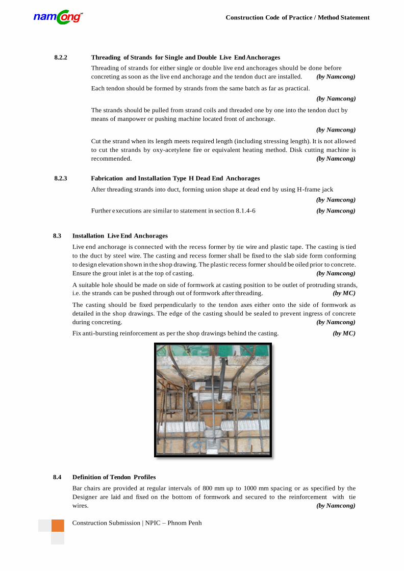
8.3 Installation Live End Anchorages
Live end anchorage is connected with the recess former by tie wire and plastic tape. The casting is tied
to the duct by steel wire. The casting and recess former shall be fixed to the slab side form conforming
to design elevation shown in the shop drawing. The plastic recess former should be oiled prior to concrete.
Ensure the grout inlet is at the top of casting. (by Namcong)
A suitable hole should be made on side of formwork at casting position to be outlet of protruding strands,
i.e. the strands can be pushed through out of formwork after threading. (by MC)
The casting should be fixed perpendicularly to the tendon axes either onto the side of formwork as
detailed in the shop drawings. The edge of the casting should be sealed to prevent ingress of concrete
during concreting. (by Namcong)
Fix anti-bursting reinforcement as per the shop drawings behind the casting. (by MC)
8.4 Definition of Tendon Profiles
Bar chairs are provided at regular intervals of 800 mm up to 1000 mm spacing or as specified by the
Designer are laid and fixed on the bottom of formwork and secured to the reinforcement with tie
wires. (by Namcong)
Construction Submission | NPIC – Phnom Penh
Construction Code of Practice / Method Statement
The ducts should be fastened properly to the bar chairs by tie wire in order to avoid displacement during
concreting. Do not fasten so tight that any damage occurs. (by Namcong)
Deviation from the theoretical cable axis (placing tolerance of duct) should not exceed ±5 mm vertically
and ±100 mm horizontally. (by Namcong)
The Main Contractor should ensure that all rebar works has been finished correctly with in acceptable
tolerances, especially highest and lowest points. The incorrect rebar arrangement may cause the
e xceeding deviation of PT tendons. (by MC)
Check visually axis of tendons and fixation at supports before concreting. Repair any damages with tape
and tie wire. (by MC, Namcong)
8.5 Finishing Works before Concreting
The grout inlet or outlet hole is provided at each live end and dead end anchorages for grouting operation.
(by Namcong)
Provide grout vents at all grout inlets of intermediate highest along the tendons with 30m maximu m of
intervals, fix by tie wires and seal by tape. (by Namcong)
All grout hoses should be closed after installation immediately to prevent any water, dust or concrete can
come inside duct during other work. These hoses can be opened before grouting only. (by Namcong)
The edge of the casting and between side of formwork and recess former should be sealed to prevent
ingress of concrete during concreting. (by Namcong)
Fix the connection between casting and plastic sleeve by tie wire and seal by tape to prevent ingress of
concrete during concreting. (by Namcong)
Seal the connection between casting and duct by tape to prevent ingress of concrete during
concreting. (by Namcong)
Cover the strand bundles by nylon strip to prevent any dust, corrosion or slurry during concreting.
(by Namcong)
Check again everything to ensure the quality, repair any damages with tape and tie wire and record in
Form “Tendon Installation & Pre -pour Inspection”. (by MC, Namcong)
The good co-operation & co-ordination between the Main-Contractor and the PT Contractor is needed due to
complicatedness of arrangement for Rebar works and Post-tensioning works on site. (by MC, Namcong)
For reference in other projects, the co-ordination between the Main-Contractor and PT Sub-Contractor
shall be:
Installation of Bottom Formwork (by MC)
Hand-over to Namcong for marking of tendon profile on formwork (by Namcong)
Installation of Bottom Rebar layers (by MC)
Hand-over to Namcong for installation of PT Tendons (by Namcong)
Installation of top rebar layers (by MC)
The hand-over work can be done area-by-area to achieve planning and schedule as required by the Client.
(by MC/Namcong)
8.6 Concreting
Pour concrete carefully and avoid any damage of duct by vibrators. (by MC)
Vibration at stressing end and dead end anchorages should be carefully performed to protect voids
or honeycomb after concrete. (by MC)
During Pour concrete, Namcong will on site in order to checking and repairing.
(by Namcong)
Construction Submission | NPIC – Phnom Penh
Construction Code of Practice / Method Statement
8.7 Installation of Anchor Head
When the concrete has attained its specified strength and the side of formwork is removed, the recess
former can be taken out and re-use for ne xt pour (Namcong recommend within 24 hours).
(by Namcong)
Arrange the protruding strand in the correct pattern to facilitate anchor block installation. It is not
necessary to cut the cable accurately to length; it is only necessary to ensure that the length is
adequate. (by Namcong)
It is important for the installation of anchor block to be carried out after concreting so that the anchorage
is not fouled by cement slurry. (by Namcong)
Check and clean the surface of the casting by removing any cement slurry adhered to it during concreting
(by Namcong)
Check and clean strands if necessary. (by Namcong)
Install anchor block onto the casting by manpower and place wedges to hold the anchor block in position
and ready for stressing. A special pipe should be used to knock the wedges to ensure the gripping of
wedges on strands. (by Namcong)
9. STRESSING OF TENDONS
(Items marked “by MC” should be done by the Main Contractor)
9.1 Preparation for Stressing
Check the validity of the jack and gauge calibration certificate. If it is over 10 months, the jacks and
gauges should be calibrated before sending to the job site for stressing operation. The jack should be
recalibrated every 10 months. (by Namcong)
Check whether the access facilities and working platforms for the stressing anchorages and dead -end
anchorages have been erected. (by MC)
Check that the bearing plates and block-outs have been cleaned of residual concrete
(by Namcong)
Verify that any damaged pockets at the anchorages have already been rectified. (by MC)
Check how the jack can be fitted up to the tendon; by hand, by crane or with special lifting
equipment. (by MC, Namcong)
Stressing can begin after the concrete has attained its specified strength shown in the design drawing and
NamCong receive the order in written from the Main Contractor.
(by MC, Namcong)
The stressing force and stressing sequence as specified on the shop drawings should be followed.
(by Namcong)
9.2 Stressing of Flat Tendons
Stressing is carried out one-by-one of strands in each tendon. (by Namcong)
Carefully check the working condition of hydraulic pump, stressing jack and gauge, power source,
hydraulic hoses connection and so on to ensure a good working for whole system.
(by Namcong)
A reference point for extension measurement is marked on every strand by painting and using a template
(Ruler). (by Namcong)
Construction Submission | NPIC – Phnom Penh
Construction Code of Practice / Method Statement
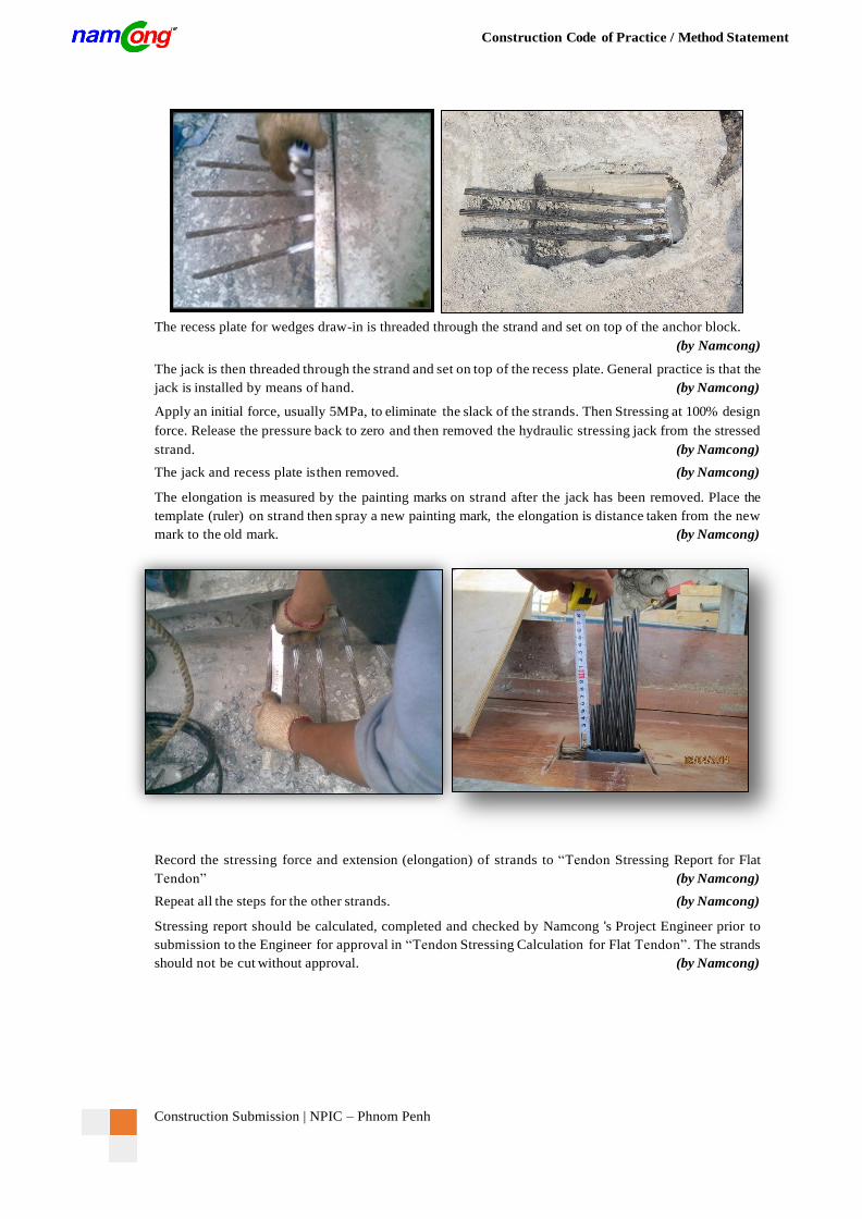
The recess plate for wedges draw-in is threaded through the strand and set on top of the anchor block.
(by Namcong)
The jack is then threaded through the strand and set on top of the recess plate. General practice is that the
jack is installed by means of hand. (by Namcong)
Apply an initial force, usually 5MPa, to eliminate the slack of the strands. Then Stressing at 100% design
force. Release the pressure back to zero and then removed the hydraulic stressing jack from the stressed
strand. (by Namcong)
The jack and recess plate is then removed. (by Namcong)
The elongation is measured by the painting marks on strand after the jack has been removed. Place the
template (ruler) on strand then spray a new painting mark, the elongation is distance taken from the new
mark to the old mark. (by Namcong)
Record the stressing force and extension (elongation) of strands to “Tendon Stressing Report for Flat
Tendon” (by Namcong)
Repeat all the steps for the other strands. (by Namcong)
Stressing report should be calculated, completed and checked by Namcong 's Project Engineer prior to
submission to the Engineer for approval in “Tendon Stressing Calculation for Flat Tendon”. The strands
should not be cut without approval. (by Namcong)
Construction Submission | NPIC – Phnom Penh
Construction Code of Practice / Method Statement
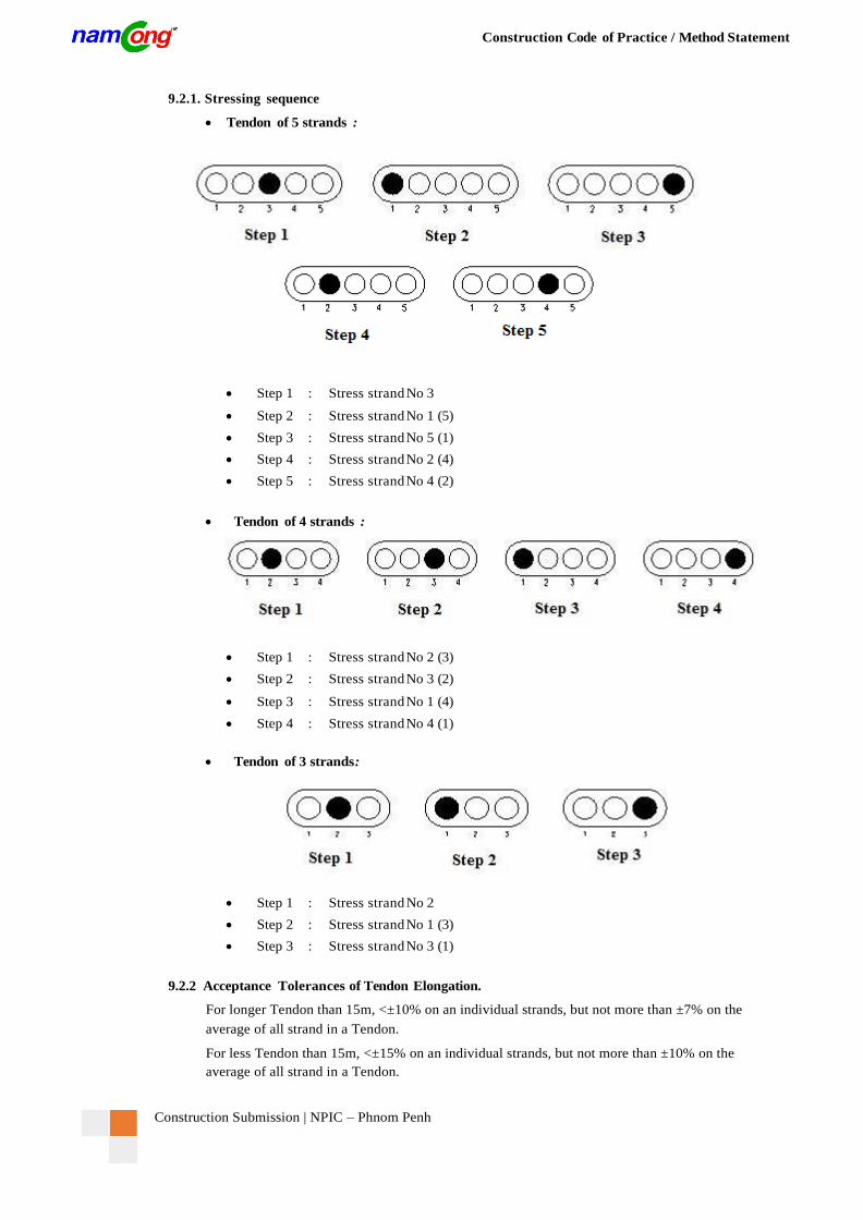
9.2.1. Stressing sequence
Tendon of 5 strands :
Step 1 : Stress strand No 3
Step 2 : Stress strand No 1 (5)
Step 3 : Stress strand No 5 (1)
Step 4 : Stress strand No 2 (4)
Step 5 : Stress strand No 4 (2)
Tendon of 4 strands :
Step 1 : Stress strand No 2 (3)
Step 2 : Stress strand No 3 (2)
Step 3 : Stress strand No 1 (4)
Step 4 : Stress strand No 4 (1)
Tendon of 3 strands :
Step 1 : Stress strand No 2
Step 2 : Stress strand No 1 (3)
Step 3 : Stress strand No 3 (1)
9.2.2 Acceptance Tolerances of Tendon Elongation.
For longer Tendon than 15m, <±10% on an individual strands, but not more than ±7% on the
average of all strand in a Tendon.
For less Tendon than 15m, <±15% on an individual strands, but not more than ±10% on the
average of all strand in a Tendon.
Construction Submission | NPIC – Phnom Penh
Construction Code of Practice / Method Statement
10. GROUTING OF TENDONS
(Items marked “by MC” should be done by the Main Contractor)
10.1 Preparation for Grouting
To provide the equipment for mortar testing on site:. (by Namcong)
Cube 100x100x100 mould: 6 set
Viscosity funnel: 1 set
Upon receipt of approval of the stressing result, protruding strands outside the anchor block are cut at
a distance measured from the anchor block of approximately two times the strand diameter or 20mm,
which ever is the bigger. (by Namcong)
For small anchorage sizes such as used for Post-tensioned slab, the recess can be patched up with
cement mortar (cement/sand ratio 1:2) instead with concrete 24 hours before grouting to prevent grout
leakage through the wedges. (by MC)
The grouting equipment should be positioned as near as possible to the grout points in order to avoid
unnecessary pressure looses in the lines. (by Namcong)
Cement and admixtures should be made available in sufficient quantities in the immediate vicinity of
the grouting equipment and be protected from moisture (splashing from the mixer, rain...) and the
water supply should be assured, if necessary by means of a water tank. (by Namcong)
10.2 Mixing Procedure
Carefully check an operation state of grout mixer before grouting to ensure that it is ready for
operation. (by Namcong)
Pour the required volume of water into the grout mixer. (by Namcong)
Turn on the grout mixer and add the pre-determined amount of grout additive Sikament NN.
(by Namcong)
Add the pre-determined amount of grout additive Expanfluid or SikaIntraplast Z-HV and mix for
another approximately 2 minutes. (by Namcong)
Then add the pre-determined amount of cement, bag by bag, to the grout pump and then mix for
approximately 2 minutes until a consistent grout mix is formed. (by Namcong)
A screen should be provided in the path of the grout circulation in order to catch cement lump (if any).
(by Namcong)
All grout tests should be carried out as in accordance with Section 11. (by Namcong)
As soon as the necessary quality control tests have been made, pumping can commence.
(by Namcong)
10.3 Grouting Procedure
Grout is pumped from one end of tendon and grout expelled from the grout hoses should be checked
until no more air bubble and the consistency of the grout is similar to that in the mixer before closing
off the hoses. (by Namcong)
Grouting of each tendon should be carried out in one continuous operation. If grouting is interrupted
for more than 30 minutes, the tendon should be flushed with water in order to clear the grout before
resuming the grouting operation. (by Namcong)
After the grout is seen flowing from the other end of the tendon, i.e. the entire tendon is filled, the
grout hoses are closed. Maintenance the pressure inside tendon about 10-15 second. (by Namcong)
The grouting nozzle should be transferred to the next already filled hose and grouting should be
continued from there. (by Namcong)
The grout hose can be cutted after 24hours Grouting. (by Namcong)
Record the grouting procedure in “Tendon Grouting Report”. (by Namcong)
Construction Submission | NPIC – Phnom Penh
Construction Code of Practice / Method Statement
11. GROUT TEST
(Items marked “by MC” should be done by the Main Contractor)
11.1 Viscosity
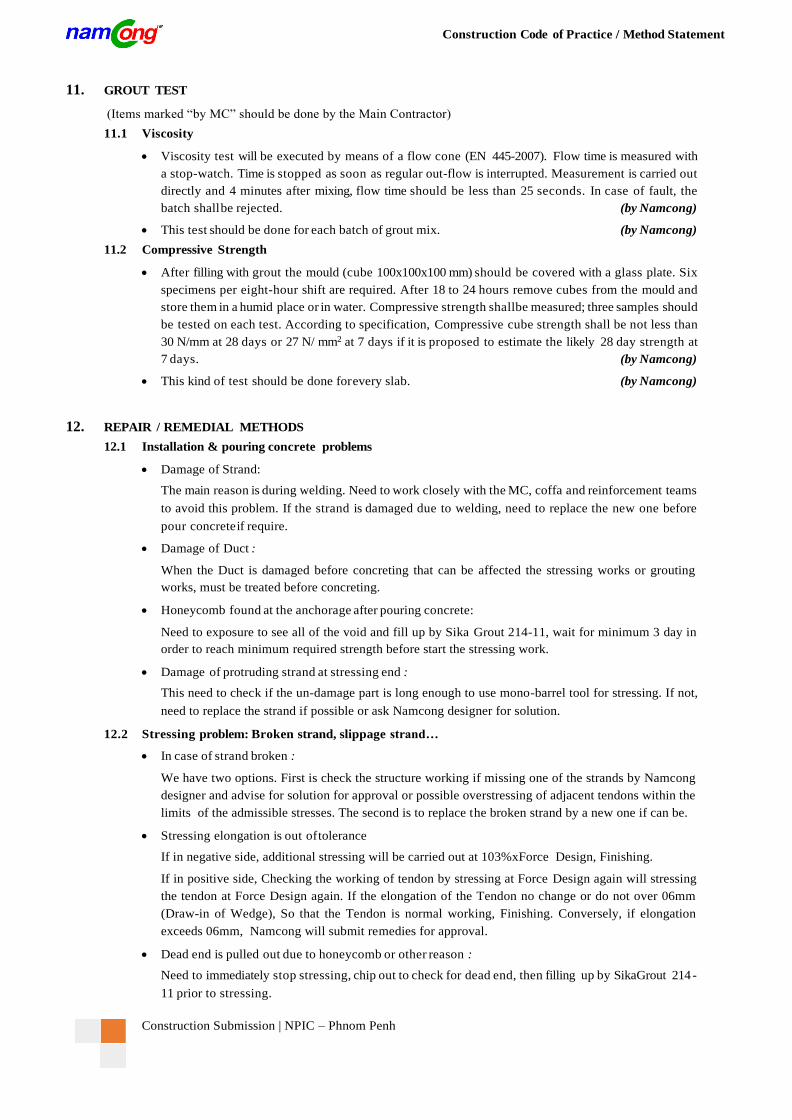
Viscosity test will be executed by means of a flow cone (EN 445-2007). Flow time is measured with
a stop-watch. Time is stopped as soon as regular out-flow is interrupted. Measurement is carried out
directly and 4 minutes after mixing, flow time should be less than 25 seconds. In case of fault, the
batch shall be rejected. (by Namcong)
This test should be done for each batch of grout mix. (by Namcong)
11.2 Compressive Strength
After filling with grout the mould (cube 100x100x100 mm) should be covered with a glass plate. Six
specimens per eight-hour shift are required. After 18 to 24 hours remove cubes from the mould and
store them in a humid place or in water. Compressive strength shallbe measured; three samples should
be tested on each test. According to specification, Compressive cube strength shall be not less than
30 N/mm at 28 days or 27 N/ mm2 at 7 days if it is proposed to estimate the likely 28 day strength at
7 days. (by Namcong)
This kind of test should be done for every slab. (by Namcong)
12. REPAIR / REMEDIAL METHODS
12.1 Installation & pouring concrete problems
Damage of Strand:
The main reason is during welding. Need to work closely with the MC, coffa and reinforcement teams
to avoid this problem. If the strand is damaged due to welding, need to replace the new one before
pour concrete if require.
Damage of Duct :
When the Duct is damaged before concreting that can be affected the stressing works or grouting
works, must be treated before concreting.
Honeycomb found at the anchorage after pouring concrete:
Need to exposure to see all of the void and fill up by Sika Grout 214-11, wait for minimum 3 day in
order to reach minimum required strength before start the stressing work.
Damage of protruding strand at stressing end :
This need to check if the un-damage part is long enough to use mono-barrel tool for stressing. If not,
need to replace the strand if possible or ask Namcong designer for solution.
12.2 Stressing problem: Broken strand, slippage strand…
In case of strand broken :
We have two options. First is check the structure working if missing one of the strands by Namcong
designer and advise for solution for approval or possible overstressing of adjacent tendons within the
limits of the admissible stresses. The second is to replace the broken strand by a new one if can be.
Stressing elongation is out of tolerance
If in negative side, additional stressing will be carried out at 103%xForce Design, Finishing.
If in positive side, Checking the working of tendon by stressing at Force Design again will stressing
the tendon at Force Design again. If the elongation of the Tendon no change or do not over 06mm
(Draw-in of Wedge), So that the Tendon is normal working, Finishing. Conversely, if elongation
exceeds 06mm, Namcong will submit remedies for approval.
Dead end is pulled out due to honeycomb or other reason :
Need to immediately stop stressing, chip out to check for dead end, then filling up by SikaGrout 214 -
11 prior to stressing.

Construction Submission | NPIC – Phnom Penh
Construction Code of Practice / Method Statement
Stuck at stressing end due to vibration damage anchorage sealing, hence concrete leaks into tendon.
This need to clear out all of debris concrete inside the anchorage before stressing.
12.3 Grouting problem: stuck at grout hose, tendon blocked…
If stuck found at any hose, need to clear it out before start grouting on that tendon.
Outlet hose stuck during grouting process need to use drilling machine directly at stuck point, or try
to inject grout from other inlet hose to blow out the stuck object. Need to report to Consultant for
approval before repairing.
Grout is leaking during grouting process, pressure is dropped down, need to use quick setting Sika
material to close the leaking point, keep continue grouting work.
13. SPECIFIC SAFETY REQUIREMENTS & PRECAUTION MEASURES
13.1 General requirement
All the construction site engineers should be responsible for safety coordination on site.
All the employees of NAMCONG shall be equipped with personal protective equipment.
Appropriate safety belt should be worn for person working at height, outside the protection of safety
bars, on scaffolding.
Any accident must be reported to the Safety Officer of the Main Contractor as soon as possible.
Scaffolding should be correctly assembled, with safety bars on each side opening on the void.
13.2 Lifting of Material and Equipment
Items to be lifted should be suspended from designated lifting points or at points such that the item being
lifted hangs in a balanced condition. (by MC, Namcong)
No person should stand or work under the load being lifted. (by MC, Namcong)
Care should be taken when stacking items in more than one layer to ensure the pile is stable.
(by MC, Namcong)
13.3 PT Tendon Installation
The working area for strand threading should be identified as an exclusion zone where only Namcong's
personnel and the representatives of the Engineer and Contractor are allowed to enter with prior
notification. (by MC, Namcong)
A warning sign should be erected at the stressing and non-stressing ends whenever stressing is in progress.
(by Namcong)
When site personnel are working beyond an exclusion zone, a plywood board should be provided in front
of the tendon at both the stressing and non-stressing ends to stop the strand in case of strand
breakage. (by Namcong)
13.4 PT Tendon Stressing
The working area for stressing should be identified as exclusion zone where only Namcong's personnel
and the representatives of the Engineer and Contractor are allowed to enter with prior notification.
(by MC, Namcong)
A warning sign should be erected at the stressing and non-stressing ends whenever stressing is in progress.
(by Namcong)
When site personnelare working beyond an exclusion zone, a plywood board should be provided in front
of the tendon at both the stressing and non-stressing ends to stop the strand in case of strand
breakage. (by Namcong)
DO NOT ALLOW ANYBODY TO STAND BEHIND THE JACK
DURING ALL STRESSING OPERATIONS
SAFETY FIRST ON CONSTRUCTION SITE

Construction Submission | NPIC – Phnom Penh
Construction Code of Practice / Method Statement
13.5 Grouting
The working area for grouting should be identified as exclusion zone where only Namcong's
personnel and the representatives of the Engineer and Contractor are allowed to enter with
prior notification. (by MC, Namcong)
Plastic gloves, dust mask and potective eye goggles should be worn when handling cement
and grout. (by Namcong)
14. EQUIPMENT & MANPOWER LIST
Refer appendix E&F for more information
15. ORGANISATION CHART
Refer appendix G for more information
Construction Submission | NPIC – Phnom Penh
Construction Code of Practice / Method Statement
16. APPENDIX A: PARTICULARS FOR GROUT MIX
16.1 Technical Data for Holcim Cement PCB 40 (or others equivalent cement)
Construction Submission | NPIC – Phnom Penh
Construction Code of Practice / Method Statement
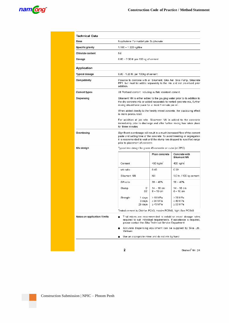
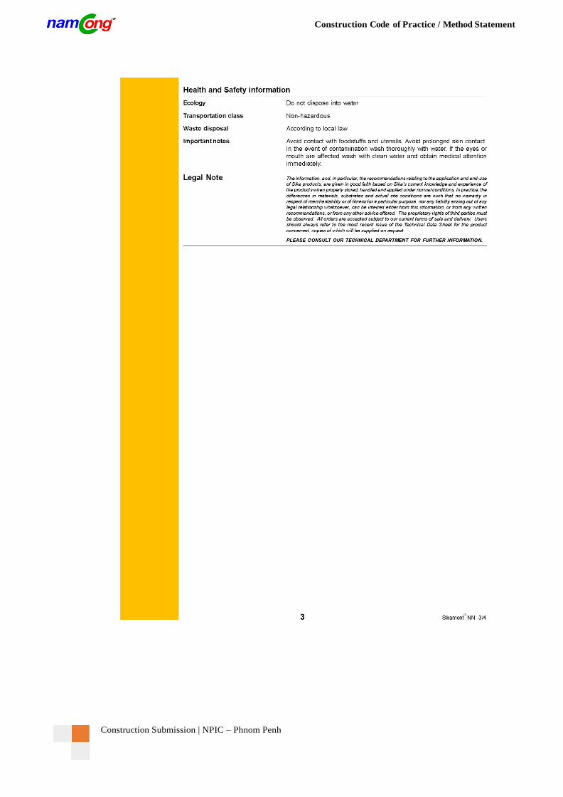
16.2 Technical Data for Grout Additive Sikament NN
Construction Submission | NPIC – Phnom Penh
Construction Code of Practice / Method Statement
Construction Submission | NPIC – Phnom Penh
Construction Code of Practice / Method Statement
Construction Submission | NPIC – Phnom Penh
Construction Code of Practice / Method Statement
17. APPENDIX B: CARE OF DUCTS AND TENDONS DURING CONCRETING
For the purposes of avoiding potential problem areas that may occur on site the main contractor is reminded of his
responsibilities in the care of NamCong ducts or tendons during the concreting phase of works.
This Appendix is extremely important as for the interest of the contract as an attempt to prevent problems occurring
during the concreting phase and prior to or during the stressing operation.
The following steps should be taken to minimize the Main Contractor’s risk of untimely site problems:
Prior to concreting, the supervisor must familiarize himself with the layout of cables and advice the
concretors of critical areas where the reinforcement and cable arrangement is particularly congested.
Throughout the concreting operation adequate chairs and planking should be used to bridge over the
prestressing ducts and prevent construction loads from damaging the ducts. Typical construction loads
include concrete pumping equipment, hand tools and treading of workers.
Vibrators of suitable diameters should be used in areas having limited spacing, especially in between
ducts and reinforcement, otherwise indentation of ducts will occur.
All poker vibrators should be labeled with color marks for the gauging of depth of penetration. This
will enable the supervisor to monitor, control and ensure correct placing and compaction of concrete
around the post - tensioning components.
Concrete should be poured layer by layer. This will increase the visibility and worker awareness of
cables and ducts.
If the ducts are covered by a thin layer of concrete, compaction of concrete can be performed reasonably
well without damaging the adjacent ducts.
Rigorous or abrupt dipping / pulling of poker vibrator should be avoided. This will cause the poker
vibrator to bounce off the reinforcement, and puncture or dent the ducts. The golden rule for dipping /
pulling the poker vibrator is “fade in” and “fade out”.
Furthermore, the poker vibrator should not be blindly submerged into the concrete without knowing
where the cables are located.
Concrete should not be discharged directly onto the duct.
Construction Submission | NPIC – Phnom Penh
Construction Code of Practice / Method Statement
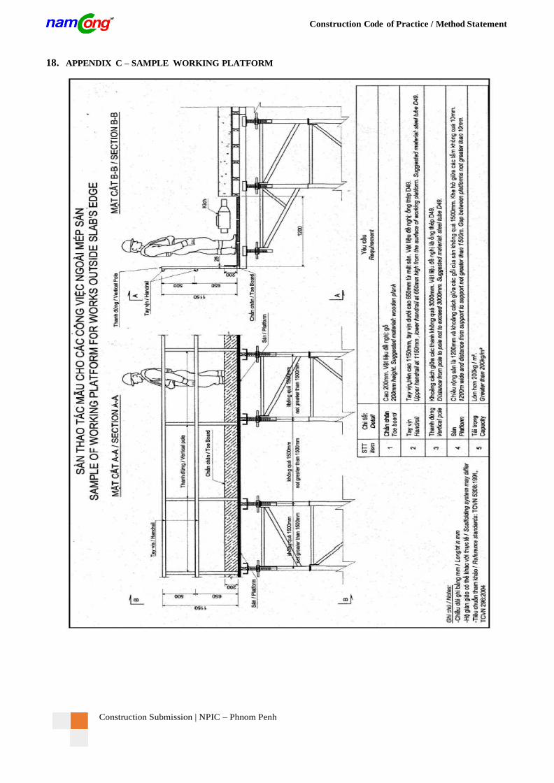
18. APPENDIX C – SAMPLE WORKING PLATFORM
Construction Submission | NPIC – Phnom Penh
Construction Code of Practice / Method Statement
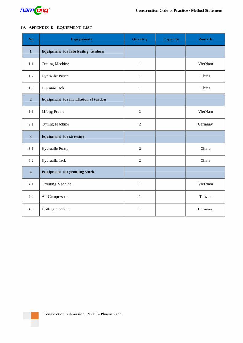
19. APPENDIX D - EQUIPMENT LIST
No Equipments Quantity Capacity Remark
1 Equipment for fabricating tendons
1.1 Cutting Machine 1
VietNam
1.2 Hydraulic Pump 1
China
1.3 H Frame Jack 1
China
2 Equipment for installation of tendon
2.1 Lifting Frame 2
VietNam
2.1 Cutting Machine 2
Germany
3 Equipment for stressing
3.1 Hydraulic Pump 2
China
3.2 Hydraulic Jack 2
China
4 Equipment for grouting work
4.1 Grouting Machine 1
VietNam
4.2 Air Compressor 1
Taiwan
4.3 Drilling machine 1
Germany
Construction Submission | NPIC – Phnom Penh
Construction Code of Practice / Method Statement
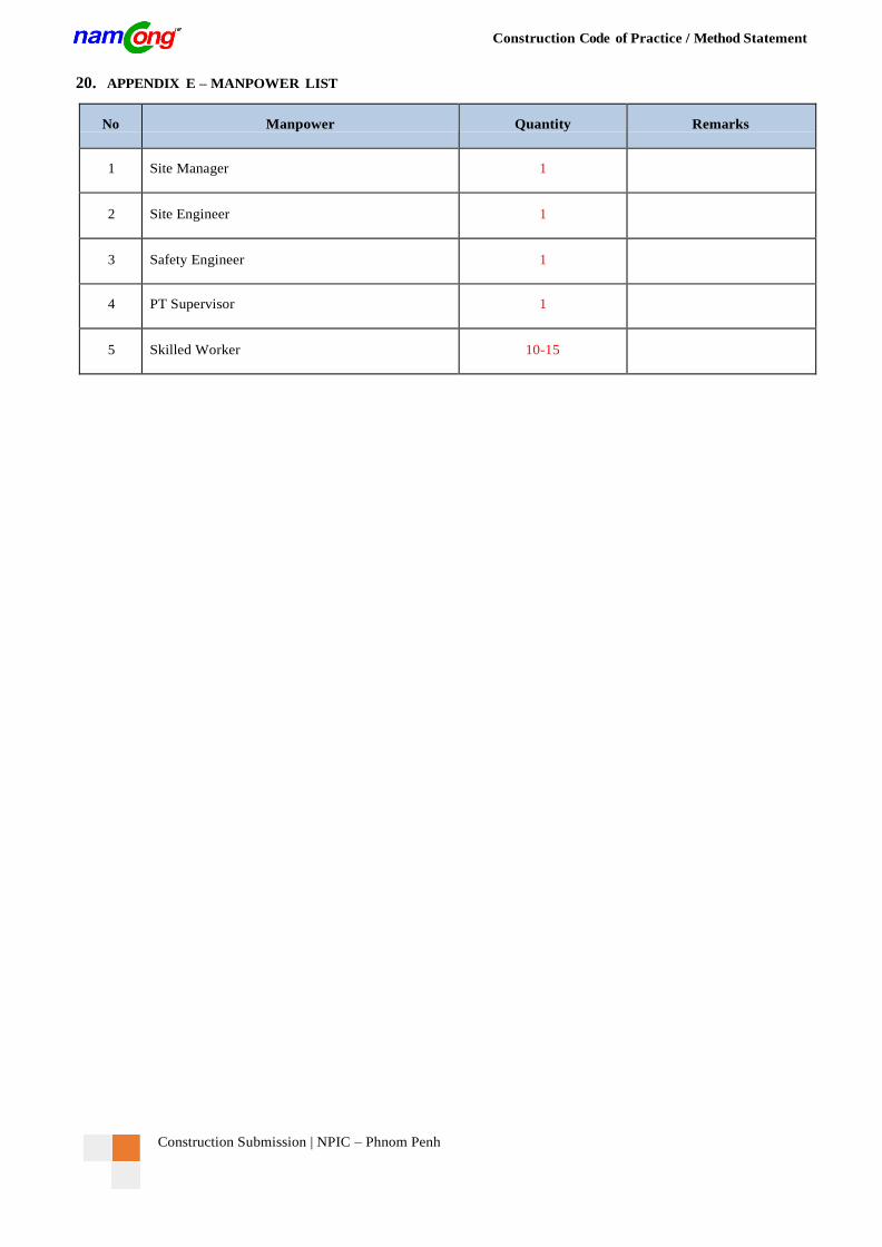
20. APPENDIX E – MANPOWER LIST
No Manpower Quantity Remarks
1 Site Manager 1
2 Site Engineer 1
3 Safety Engineer 1
4 PT Supervisor 1
5 Skilled Worker 10-15
Construction Submission | NPIC – Phnom Penh
Construction Code of Practice / Method Statement
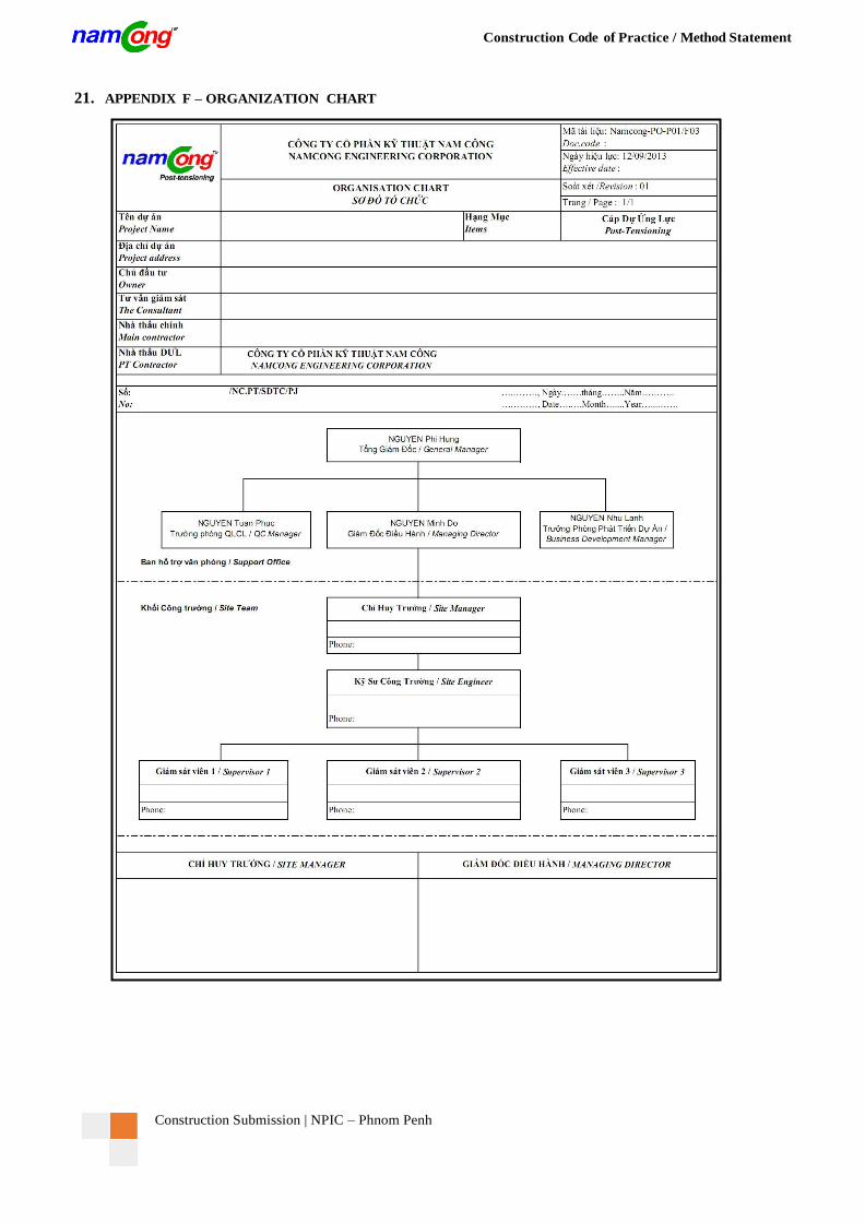
21. APPENDIX F – ORGANIZATION CHART