00908 Litchfield Geotechnical Report (09-12-17)
81
CT DOT Bridge No. 00908 Geotechnical Report Route 202 over Bantam River, Litchfield, Connecticut Submitted to: Parsons Transportation Group 100 High Street, 4 th Floor Boston, MA 02110 Prepared by: GEI Consultants, Inc. 455 Winding Brook Drive, Suite 201 Glastonbury, CT 06033 September 12, 2017 GEI Project 1328830 Matthew Glunt, P.E. Anna Hernberg, P.E. Senior Geotechnical Engineer Geotechnical Engineer Consulting Engineers and Scientists
Transcript of 00908 Litchfield Geotechnical Report (09-12-17)
CT DOT Bridge No. 00908
Geotechnical Report Route 202 over Bantam River, Litchfield, Connecticut
Submitted to: Parsons Transportation Group 100 High Street, 4th Floor Boston, MA 02110
Prepared by: GEI Consultants, Inc. 455 Winding Brook Drive, Suite 201 Glastonbury, CT 06033
September 12, 2017
GEI Project 1328830
Matthew Glunt, P.E. Anna Hernberg, P.E. Senior Geotechnical Engineer Geotechnical Engineer
Consulting Engineers and Scientists
CT DOT Bridge No. 00908 Route 202 Over Bantam River Litchfield, Connecticut September 12, 2017
GEI Consultants, Inc. i
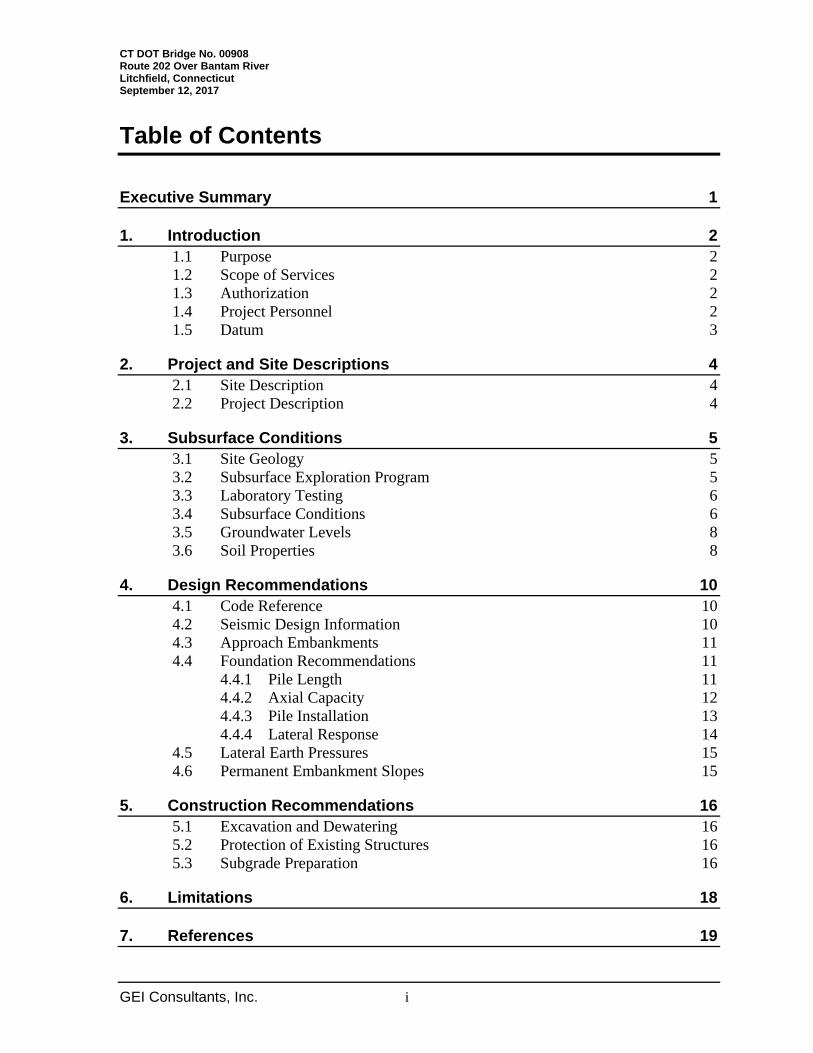
Table of Contents
Executive Summary 1
1. Introduction 2 1.1 Purpose 2 1.2 Scope of Services 2 1.3 Authorization 2 1.4 Project Personnel 2 1.5 Datum 3
2. Project and Site Descriptions 4 2.1 Site Description 4 2.2 Project Description 4
3. Subsurface Conditions 5 3.1 Site Geology 5 3.2 Subsurface Exploration Program 5 3.3 Laboratory Testing 6 3.4 Subsurface Conditions 6 3.5 Groundwater Levels 8 3.6 Soil Properties 8
4. Design Recommendations 10 4.1 Code Reference 10 4.2 Seismic Design Information 10 4.3 Approach Embankments 11 4.4 Foundation Recommendations 11
4.4.1 Pile Length 11 4.4.2 Axial Capacity 12 4.4.3 Pile Installation 13 4.4.4 Lateral Response 14
4.5 Lateral Earth Pressures 15 4.6 Permanent Embankment Slopes 15
5. Construction Recommendations 16 5.1 Excavation and Dewatering 16 5.2 Protection of Existing Structures 16 5.3 Subgrade Preparation 16
6. Limitations 18
7. References 19
CT DOT Bridge No. 00908 Route 202 Over Bantam River Litchfield, Connecticut September 12, 2017
GEI Consultants, Inc. ii
Appendices A. Figures and Tables B. Boring Logs C. Laboratory Test Results D. Geotechnical Calculations
Figures 1. Site Location Map 2. Boring Location Plan 3. Subsurface Profile
Tables A-1 Boring Locations A-2 Exploration Data A-3 Laboratory Testing Results A-4 Corrected Standard Penetration Test N-Values
CT DOT Bridge No. 00908 Route 202 over Bantam River Litchfield, Connecticut September 12, 2017
GEI Consultants, Inc. 1
Executive Summary
This report presents the results of the subsurface exploration and our geotechnical recommendations regarding replacement of ConnDOT Bridge No. 00908 carrying Route 202 over the Bantam River in Litchfield, Connecticut. Current plans call for replacement of the bridge with a new two-span structure supported by cast-in-place abutments and a center pier. The bridge width will be increased by approximately 4 feet on each side, which will also require 350 feet of roadway construction on the tapering approaches. Demolition and construction of the bridge will be conducted in two stages, utilizing alternating one-way traffic to maintain flow. Cofferdams and temporary excavation support will be required. New England Boring Contractors, Inc. drilled five borings between November 13 and November 19, 2013. Two additional borings were offset and drilled after shallow refusals occurred. Soil conditions generally consist of granular embankment fill overlying alluvial sands and silts, native sands and gravels, and dense glacial tills. Some of the fill contains cobbles and boulders. Groundwater was encountered approximately 6 feet to 10 feet below the roadway surface. The abutments and center pier will be founded on steel H-piles driven to bedrock. A resistance factor of 0.65 should be used, in conjunction with PDA and CAPWAP testing of one pile at each abutment. The center pier piles and a portion of the abutment piles may be battered as shown on the plans to provide added lateral resistance. We estimate a factored geotechnical resistance of 278 kips will be available for HP 14x73 piles driven to bedrock at the Strength Limit state. Piles should be fitted with driving pile points to protect the tips and improve penetration. The depth to bedrock, as measured by the borings, varied by up to 2 feet transversely across each proposed structure, and up to 7 feet along the full length of the bridge.
There is a business about 150 feet north of the bridge that maintains large compressed gas tanks set on elevated concrete piers. As such, we recommend conducting vibration monitoring during pile installation near the north abutment. A limiting peak particle velocity (PPV) of 0.5 inches/second may be assumed for preliminary discussion, with the final limiting value determined in conjunction with the owner. Per the ConnDOT Bridge Design Manual, this bridge will be required to be analyzed and designed for seismic forces. Based on Standard Penetration Test N-values, the bridge site should be classified as Site Class D. We did not evaluate the potential for liquefaction because the bridge is in Seismic Zone 1, per AASHTO specifications.
CT DOT Bridge No. 00908 Route 202 Over Bantam River Litchfield, Connecticut September 12, 2017
GEI Consultants, Inc. 2
1. Introduction
1.1 Purpose
The project consists of replacement of the Route 202 (Torrington Road) bridge over the Bantam River (Bridge No. 00908) in Litchfield, Connecticut. The project location and proposed structures are shown on Figures 1 and 3. GEI Consultants, Inc. (GEI) was retained by Parsons Transportation Group (Parsons) to perform a subsurface exploration and prepare this Geotechnical Report in support of the design effort. This report presents the results of the subsurface explorations, our evaluation of the existing subsurface conditions, and our recommendations for foundation support.
1.2 Scope of Services
GEI’s scope of work for this project included the following:
1. Reviewed available published geologic data, existing bridge plans, and proposed bridge design information provided to us.
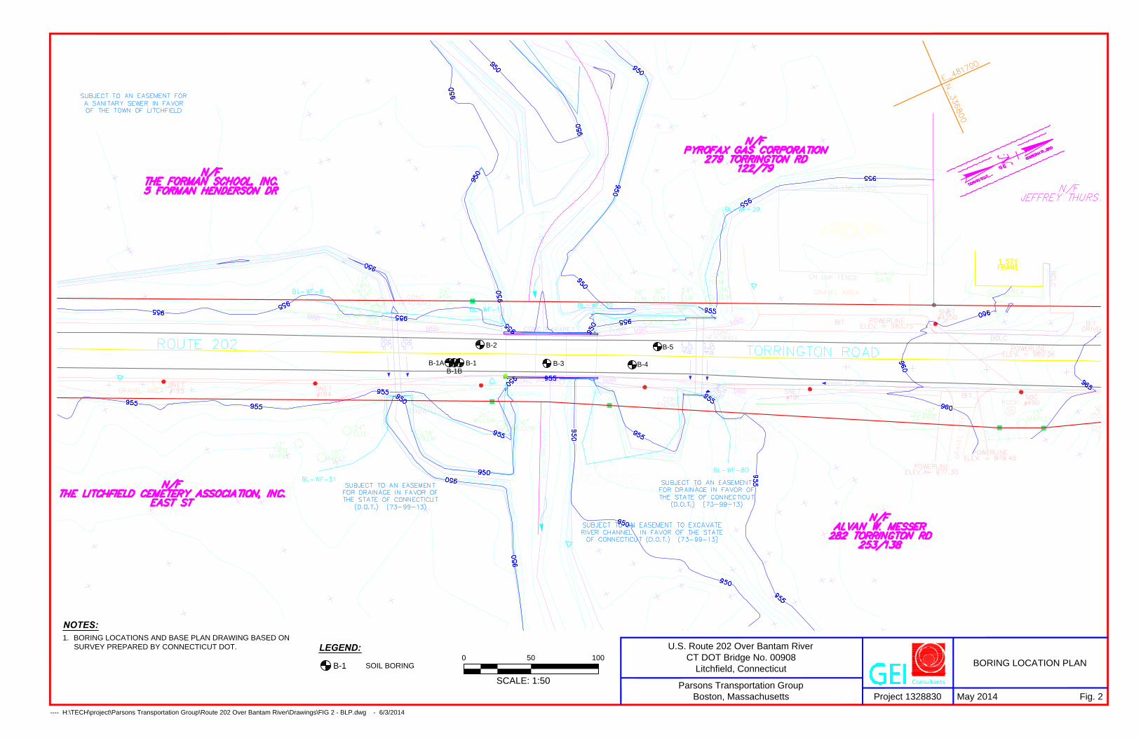
2. Developed a subsurface exploration program with Parsons, consisting of five borings, two for each abutment and one at the center of the bridge deck.
3. Provided full-time observation of the test borings and classified recovered samples in general accordance with ConnDOT Geotechnical Engineering Manual.
4. Assigned and coordinated laboratory testing on samples collected from the test borings.
5. Reviewed the results of the test borings, prepared a subsurface profile, and developed soil properties for analyses.
6. Evaluated alternate foundation types for the bridge and provided foundation recommendations. Evaluated the axial and lateral capacity of deep foundation elements.
1.3 Authorization
Our work was performed in accordance with the terms and conditions of our Professional Services Agreement with Parsons dated September 3, 2013.
1.4 Project Personnel
The following personnel at GEI were involved with this project:

CT DOT Bridge No. 00908 Route 202 Over Bantam River Litchfield, Connecticut September 12, 2017
GEI Consultants, Inc. 3
Matthew Glunt, P.E. Project Manager Peter Heynen, P.E. In-House Technical Review Anna Hernberg, P.E. Geotechnical Engineer Russell Morang Engineering Technician
1.5 Datum
The elevations and State Plane coordinates shown on Table A-1 and referenced in this report for the test boring locations were surveyed by ConnDOT and provided to GEI. Northing and easting coordinates are referenced to NAD 83 (2011) while elevations are referenced to NAVD 1988.
CT DOT Bridge No. 00908 Route 202 Over Bantam River Litchfield, Connecticut September 12, 2017
GEI Consultants, Inc. 4
2. Project and Site Descriptions
2.1 Site Description
Bridge No. 00908, built in 1931, is a three-span bridge with a reinforced concrete deck. The bridge carries two lanes of traffic along Route 202 (Torrington Road) over the Bantam River, approximately 0.75 miles northeast of the Route 202 intersection with Route 63 in the Town of Litchfield, as shown on Figure 1.
GEI was provided a copy of the September 2010 Rehabilitation Study Report (RSR) prepared by BL Companies. The bridge substructure consists of two unreinforced concrete abutments, four unreinforced concrete flared wingwalls, and two unreinforced concrete piers. The substructure supports reinforced concrete slabs. Pile foundations are shown on the record plans for the north abutment and pier; however, no piles were actually driven. The as-built plans indicate that steel sheet piling was driven and used as forms for the concrete foundations.
The total structure length is 68 feet and the span length is 20 feet. The existing roadway approaches consist of two 12-foot travel lanes and two 8-foot shoulders. However, the road narrows to match the existing bridge width of 32 feet.
2.2 Project Description
As stated in the RSR, the bridge was found to be structurally deficient and functionally obsolete principally due to insufficient travel width, hydraulic capacity, and structural deficiencies in the deck. The bridge is also listed as “scour critical” due to localized scour at the west end of Pier 1. Plans provided by Parsons dated September 19, 2014, for the Semi-Final design review indicate full replacement of the bridge with a new approximately 93-foot, two-span structure. A simply supported, pre-stressed concrete deck will be supported by cast-in-place reinforced abutments and a center pier. The existing concrete abutments and north pier will be cut off as shown on the plans to serve as scour protection. The bridge width will be increased by approximately 4 feet on each side, which will also require 350 feet of roadway construction on the tapering approaches. Demolition and construction of the bridge will be conducted in two stages, utilizing alternating one-way traffic to maintain flow. Cofferdams and temporary excavation support will be required to construct the new bridge.

CT DOT Bridge No. 00908 Route 202 Over Bantam River Litchfield, Connecticut September 12, 2017
GEI Consultants, Inc. 5
3. Subsurface Conditions
3.1 Site Geology
Mapped surficial geology (CTDEEP, 2010) near the bridge site is described as un-differentiated glacial meltwater deposits and post-glacial floodplain alluvium and swamp deposits. The meltwater deposits are prevalent in the valleys and lowlands of Connecticut where sediments were laid down in glacial lakes, streams, and ponds as the ice sheet melted north. Floodplain alluvium and swamp deposits are common in low-lying inland areas and waterways and overlie the glacial meltwater deposits. Bedrock is mapped as part of the Rowe Schist formation (Rodgers, 1985).
3.2 Subsurface Exploration Program
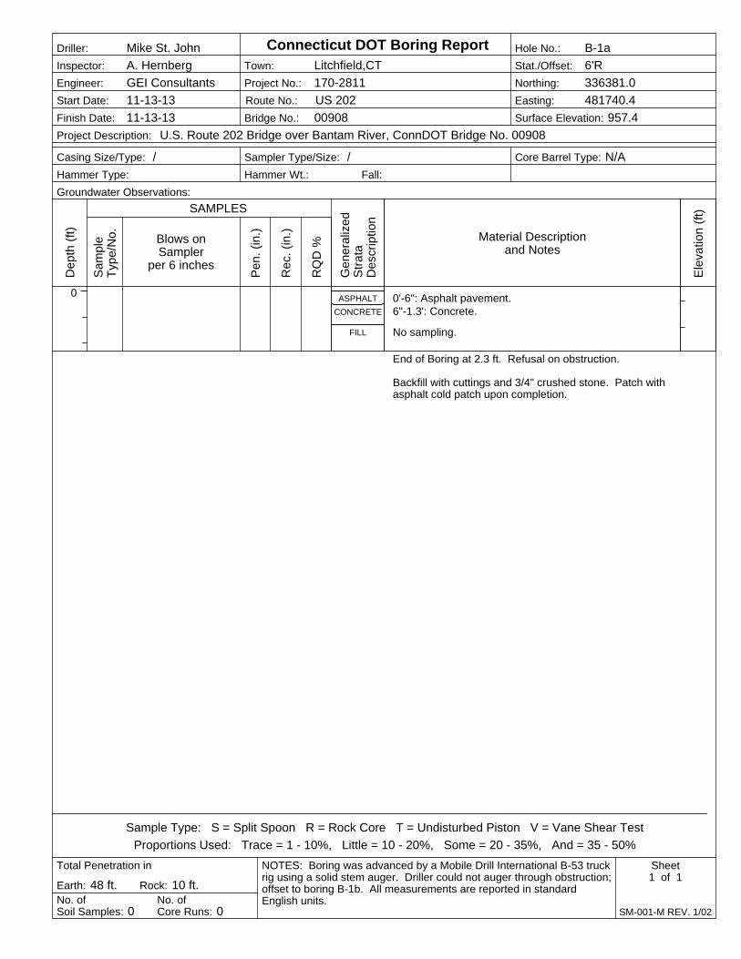
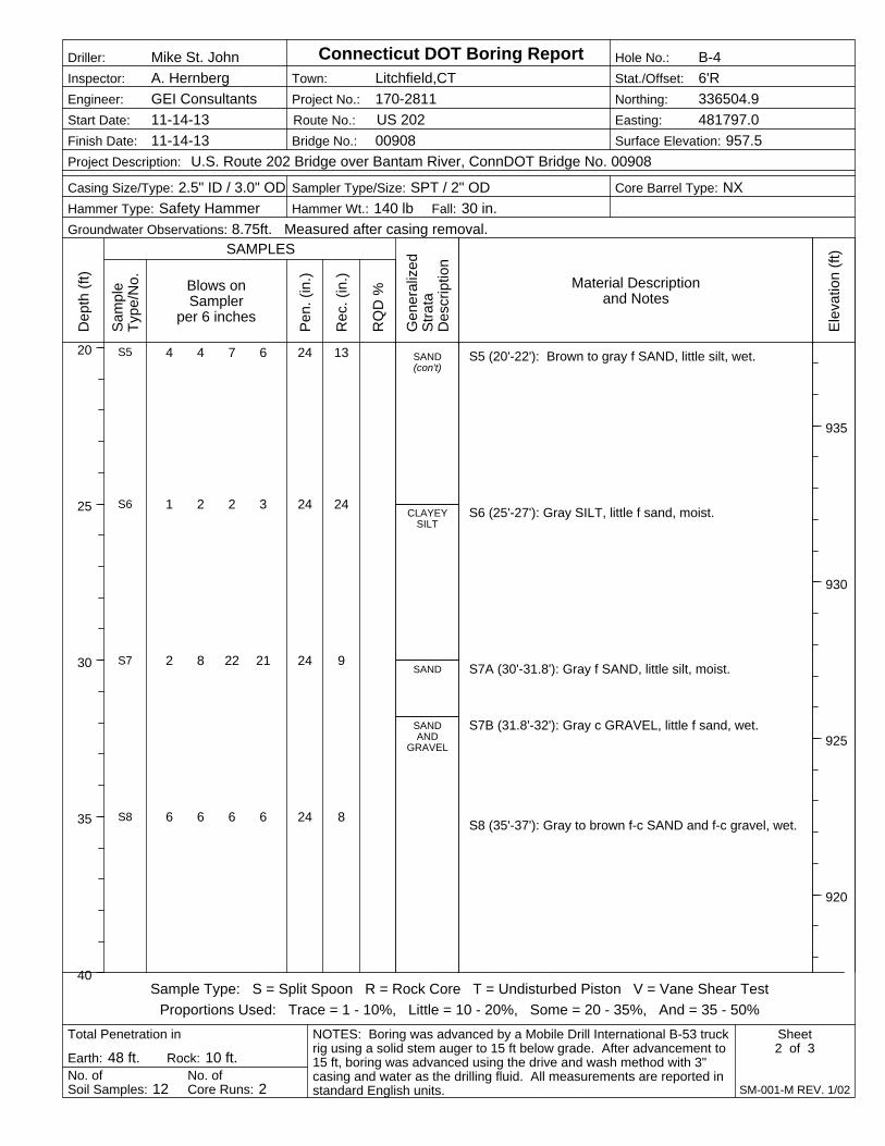
New England Boring Contractors, Inc., under subcontract to GEI, drilled five borings (B-1, B-2, B-3, B-4, and B-5) between November 13 and November 19, 2013. Two additional borings (B-1a and B-1b) were offset and drilled after shallow refusals occurred. A GEI representative was on-site full time to observe the drilling procedures and classify the soil samples. Solid stem augers were utilized to collect samples at depths of 10 feet to 15 feet from the ground surface. The borings were further advanced using drive and wash techniques to the top of bedrock at depths ranging from 46.5 feet to 52.0 feet. Rock core samples approximately 10 feet in length were then obtained from each boring. Standard Penetration tests and split-spoon sampling in general accordance with ASTM D1586 were generally taken continuously in the upper 12 feet, then at 5-foot intervals thereafter. The Mobile Drill International B-53 truck-mounted drilling rig used was equipped with a 140-lb safety hammer. Boring logs are presented in Appendix B. Surveyed boring locations and stratifications are summarized in Tables A-1 and A-2, respectively. Standard Penetration Test N-values, corrected (normalized) for overburden pressure and hammer type, are provided in Table A-4 for all SPT samples collected. Boreholes behind the existing abutments were backfilled with drill cuttings and ¾” crushed stone after they were completed. Boring B-3 from the bridge deck was patched with quick-setting concrete. All borings were patched at the surface using cold patch asphalt.
CT DOT Bridge No. 00908 Route 202 Over Bantam River Litchfield, Connecticut September 12, 2017
GEI Consultants, Inc. 6
3.3 Laboratory Testing
Laboratory testing was performed on selected samples collected during the exploration program. Testing was performed by TerraSense, LLC of Totowa, New Jersey, under subcontract to GEI. Grain size analyses, atterberg limits tests, and an organic content test were performed to aid in soil classification and estimation of engineering properties.
A summary of laboratory testing performed on samples collected by GEI is presented in Table A-3. Printouts of laboratory test results are presented in Appendix C.
3.4 Subsurface Conditions
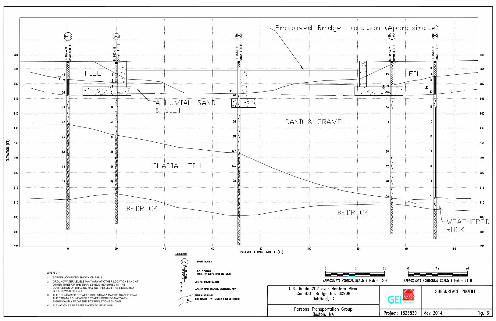
Based on our review of the available geotechnical information, the general soil strata are as follows, beginning at the ground surface. A subsurface profile across the bridge is provided on Figure 3 and includes a sketch of the new bridge layout. The subsurface conditions are known only at the exploration locations. Conditions between explorations may differ significantly from those shown in the subsurface profiles and described below.
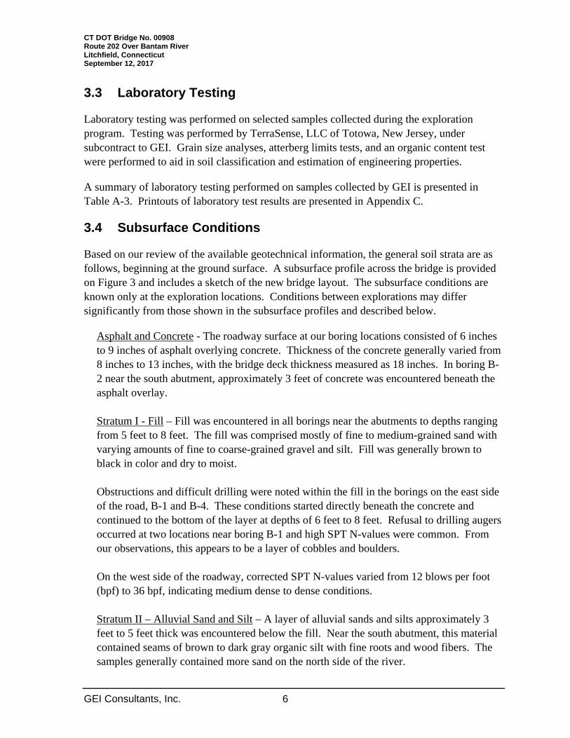
Asphalt and Concrete - The roadway surface at our boring locations consisted of 6 inches to 9 inches of asphalt overlying concrete. Thickness of the concrete generally varied from 8 inches to 13 inches, with the bridge deck thickness measured as 18 inches. In boring B-2 near the south abutment, approximately 3 feet of concrete was encountered beneath the asphalt overlay. Stratum I - Fill – Fill was encountered in all borings near the abutments to depths ranging from 5 feet to 8 feet. The fill was comprised mostly of fine to medium-grained sand with varying amounts of fine to coarse-grained gravel and silt. Fill was generally brown to black in color and dry to moist. Obstructions and difficult drilling were noted within the fill in the borings on the east side of the road, B-1 and B-4. These conditions started directly beneath the concrete and continued to the bottom of the layer at depths of 6 feet to 8 feet. Refusal to drilling augers occurred at two locations near boring B-1 and high SPT N-values were common. From our observations, this appears to be a layer of cobbles and boulders. On the west side of the roadway, corrected SPT N-values varied from 12 blows per foot (bpf) to 36 bpf, indicating medium dense to dense conditions. Stratum II – Alluvial Sand and Silt – A layer of alluvial sands and silts approximately 3 feet to 5 feet thick was encountered below the fill. Near the south abutment, this material contained seams of brown to dark gray organic silt with fine roots and wood fibers. The samples generally contained more sand on the north side of the river.
CT DOT Bridge No. 00908 Route 202 Over Bantam River Litchfield, Connecticut September 12, 2017
GEI Consultants, Inc. 7
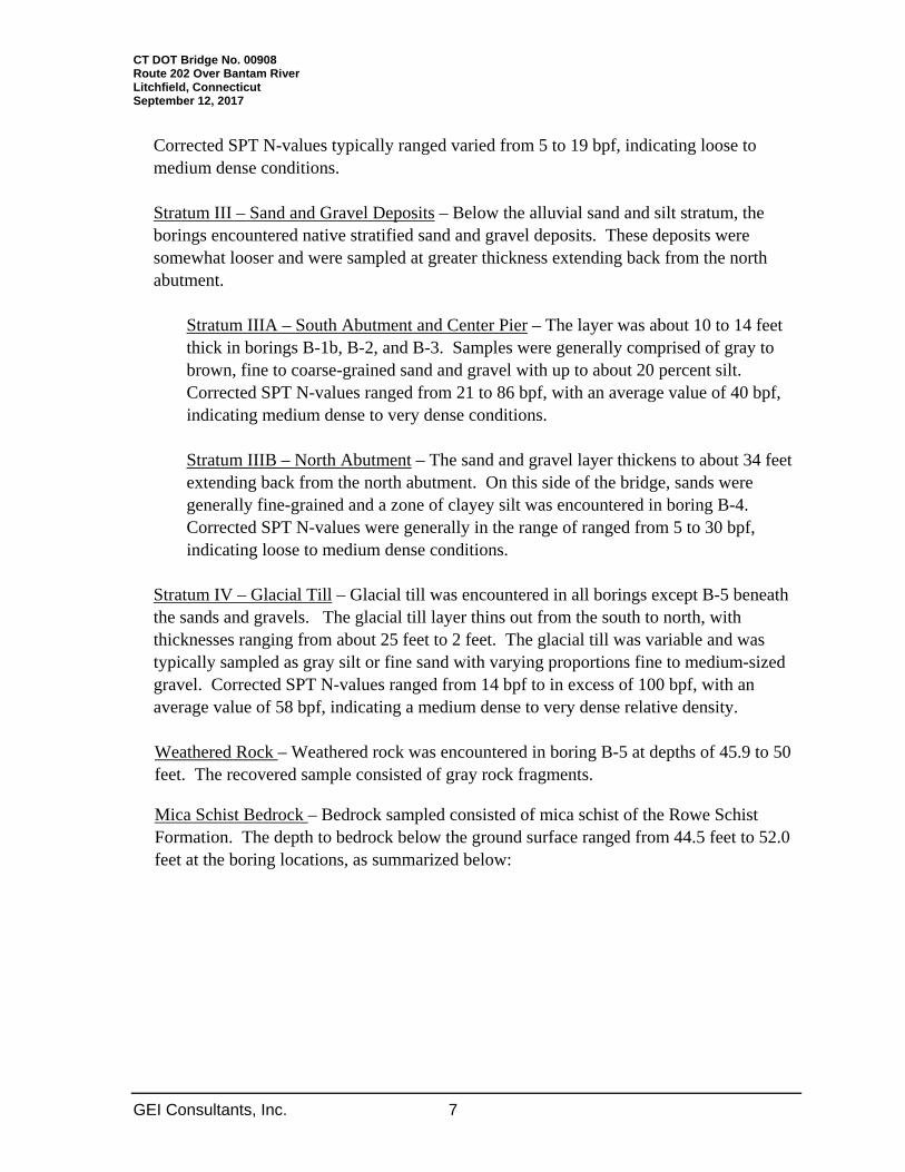
Corrected SPT N-values typically ranged varied from 5 to 19 bpf, indicating loose to medium dense conditions. Stratum III – Sand and Gravel Deposits – Below the alluvial sand and silt stratum, the borings encountered native stratified sand and gravel deposits. These deposits were somewhat looser and were sampled at greater thickness extending back from the north abutment.
Stratum IIIA – South Abutment and Center Pier – The layer was about 10 to 14 feet thick in borings B-1b, B-2, and B-3. Samples were generally comprised of gray to brown, fine to coarse-grained sand and gravel with up to about 20 percent silt. Corrected SPT N-values ranged from 21 to 86 bpf, with an average value of 40 bpf, indicating medium dense to very dense conditions. Stratum IIIB – North Abutment – The sand and gravel layer thickens to about 34 feet extending back from the north abutment. On this side of the bridge, sands were generally fine-grained and a zone of clayey silt was encountered in boring B-4. Corrected SPT N-values were generally in the range of ranged from 5 to 30 bpf, indicating loose to medium dense conditions.
Stratum IV – Glacial Till – Glacial till was encountered in all borings except B-5 beneath the sands and gravels. The glacial till layer thins out from the south to north, with thicknesses ranging from about 25 feet to 2 feet. The glacial till was variable and was typically sampled as gray silt or fine sand with varying proportions fine to medium-sized gravel. Corrected SPT N-values ranged from 14 bpf to in excess of 100 bpf, with an average value of 58 bpf, indicating a medium dense to very dense relative density. Weathered Rock – Weathered rock was encountered in boring B-5 at depths of 45.9 to 50 feet. The recovered sample consisted of gray rock fragments.
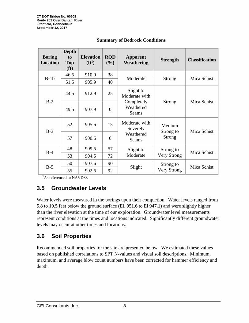
Mica Schist Bedrock – Bedrock sampled consisted of mica schist of the Rowe Schist Formation. The depth to bedrock below the ground surface ranged from 44.5 feet to 52.0 feet at the boring locations, as summarized below:
CT DOT Bridge No. 00908 Route 202 Over Bantam River Litchfield, Connecticut September 12, 2017
GEI Consultants, Inc. 8
Summary of Bedrock Conditions
Boring Location
Depth to
Top (ft)
Elevation(ft1)
RQD(%)
Apparent Weathering
Strength Classification
B-1b 46.5 910.9 38
Moderate Strong Mica Schist 51.5 905.9 40
B-2
44.5 912.9 25 Slight to
Moderate with Completely Weathered
Seams
Strong Mica Schist
49.5 907.9 0
B-3
52 905.6 15 Moderate with Severely
Weathered Seams
Medium Strong to
Strong Mica Schist
57 900.6 0
B-4 48 909.5 57 Slight to
Moderate Strong to
Very Strong Mica Schist
53 904.5 72
B-5 50 907.6 90
Slight Strong to
Very Strong Mica Schist
55 902.6 92 1As referenced to NAVD88
3.5 Groundwater Levels
Water levels were measured in the borings upon their completion. Water levels ranged from 5.8 to 10.5 feet below the ground surface (El. 951.6 to El 947.1) and were slightly higher than the river elevation at the time of our exploration. Groundwater level measurements represent conditions at the times and locations indicated. Significantly different groundwater levels may occur at other times and locations.
3.6 Soil Properties
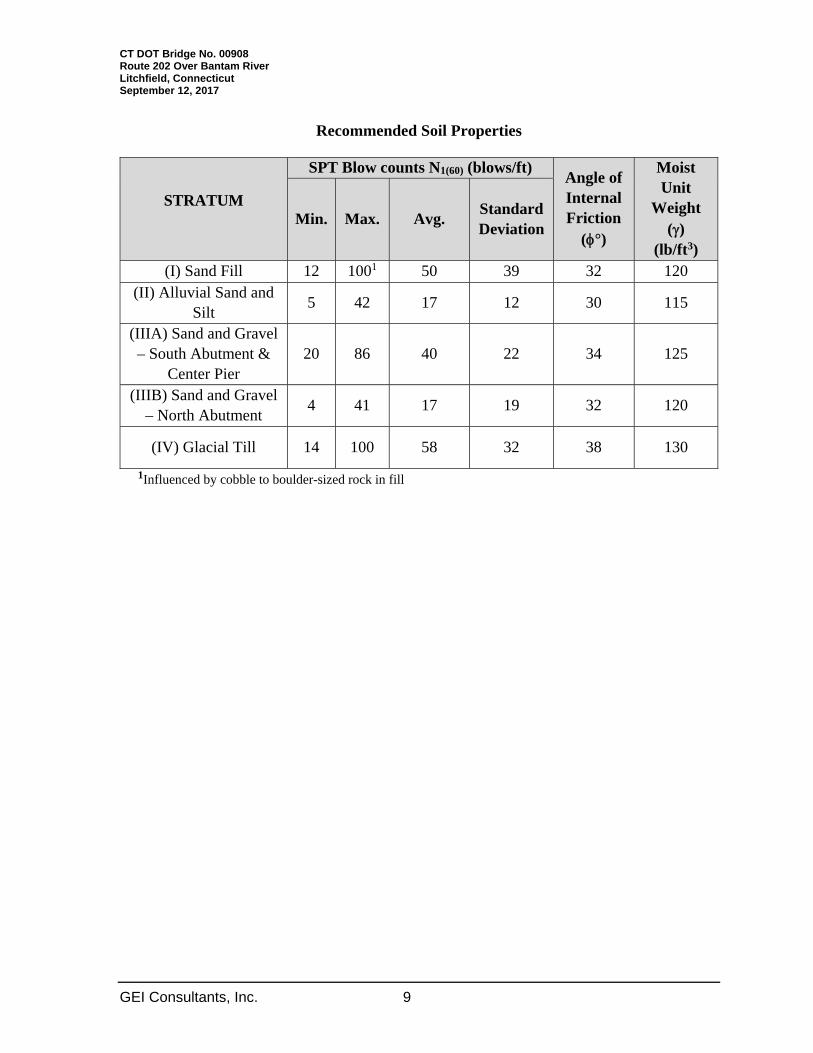
Recommended soil properties for the site are presented below. We estimated these values based on published correlations to SPT N-values and visual soil descriptions. Minimum, maximum, and average blow count numbers have been corrected for hammer efficiency and depth.
CT DOT Bridge No. 00908 Route 202 Over Bantam River Litchfield, Connecticut September 12, 2017
GEI Consultants, Inc. 9
Recommended Soil Properties
STRATUM
SPT Blow counts N1(60) (blows/ft) Angle of Internal Friction
(°)
Moist Unit
Weight ()
(lb/ft3)
Min. Max. Avg. StandardDeviation
(I) Sand Fill 12 1001 50 39 32 120 (II) Alluvial Sand and
Silt 5 42 17 12 30 115
(IIIA) Sand and Gravel – South Abutment &
Center Pier 20 86 40 22 34 125
(IIIB) Sand and Gravel – North Abutment
4 41 17 19 32 120
(IV) Glacial Till 14 100 58 32 38 130
1Influenced by cobble to boulder-sized rock in fill

CT DOT Bridge No. 00908 Route 202 Over Bantam River Litchfield, Connecticut September 12, 2017
GEI Consultants, Inc. 10
4. Design Recommendations
Recommendations presented herein are referenced to the bridge layout provided by Parsons. The design criteria presented herein should be reviewed by GEI for continued applicability if revisions are made by the design team concerning bridge configuration, design loads, etc.
4.1 Code Reference
Our services were performed in general conformance with the ConnDOT Geotechnical Engineering Manual and our approved scope dated August 13, 2013. Project design parameters and computations generally follow those described in the relevant sections of the AASHTO LRFD Bridge Design Specifications (AASHTO 6th Ed., 2012, with interims through 2013), supplemented by the most recent editions of the ConnDOT Bridge Design Manual and Geotechnical Engineering Manual.
4.2 Seismic Design Information
The recommended alternative for this bridge is a full replacement with a new structure. According to ConnDOT’s Bridge Design Manual, “Section 4 Seismic Design and Retrofit”, which supplements the AASHTO LRFD Bridge Design Specifications, new bridges shall be analyzed and designed for seismic forces.
Based on Standard Penetration Test N-values from the borings performed during our work, and in accordance with Article 3.10.3.1 of the AASHTO Bridge Specifications, we recommend that the project be classified as Site Class D. The 2003 ConnDOT Bridge Design Manual recommends the use of a seismic acceleration of 0.16g for design of bridge structures. We understand that the Manual is currently being revised and expect that the revised Manual will reference current AASHTO design requirements. Based on this understanding, we recommend the following seismic design criteria, based on a seven percent probability of exceedance in a 75-year period (approximate return period of 1,000 years) per Section 3 of the AASHTO LRFD Bridge Design Specifications (AASHTO 6th Ed., 2012). Mapped Seismic Hazard (Site Class D) Peak Ground Acceleration Coefficient (PGA) = 0.064g Spectral Acceleration Coefficient (period = 0.2 sec) (SS) = 0.136g Spectral Acceleration Coefficient (period = 1.0 sec) (S1) = 0.037g The resulting parameters for calculation of the design response spectrum are:

CT DOT Bridge No. 00908 Route 202 Over Bantam River Litchfield, Connecticut September 12, 2017
GEI Consultants, Inc. 11
Site-corrected Peak Ground Acceleration (AS) = 0.102g Short Period Response Acceleration (SDS) = 0.217 g Long Period Response Acceleration (SD1) = 0.089g Seismic Zone: 1 (per Table 3.10.6.1) As per AASHTO 10.5.4.2, we did not evaluate the potential for liquefaction because the bridge is in Seismic Zone 1.
4.3 Approach Embankments
The replacement scheme shown in the RSR and plans indicates the bridge deck will be widened by 4 feet on each side to comply with current design standards. This will require placement of new fill on the existing embankments for about 60 feet back from each new abutment. Extended U-type wingwalls will contain most of the approach fill. From the available topographic survey (dated December 2008), widening near the abutments will require about 1 foot to 2 feet of fill above present grade. Installation of the abutments and adjacent wingwalls will require about 10 feet of excavation below present grade. New fill will thin out away from the bridge as it meets up with the existing shoulder. Placing up to 2 feet of fill on the existing shoulders and embankment will cause some settlement of the underlying soils. However, we expect these settlements to be relatively minor, on the order of 1 inch or less, and be nearly complete at the end of construction. Preparing the subgrade in accordance with ConnDOT specifications will help to reduce these settlements. Excavation of existing embankment soils and replacement with new fill behind the abutments may also cause slight settlements as the foundation soils are unloaded then rebound to the present stress level. 4.4 Foundation Recommendations
Steel H-piles driven to bedrock are recommended for support of the planned abutments and center pier.
4.4.1 Pile Length
The depth to bedrock, as measured by the borings, varied by up to 2 feet transversely across each proposed structure, and up to 7 feet along the full length of the bridge. One foot of embedment into the structure and one foot into the bedrock was assumed for length estimates. Based on the results of our investigation, order lengths may be presented as follows:

CT DOT Bridge No. 00908 Route 202 Over Bantam River Litchfield, Connecticut September 12, 2017
GEI Consultants, Inc. 12
Recommended Pile Lengths
Structure Pile Orientation Recommended Pile Order Length (feet)
Recommended Test Pile Length (feet)
Abutment 1; Wingwalls 1A/1B
Plumb 40 45 1H:3V 45 50 1H:6V 40 45
Center Pier 1H:3V 45 50 Abutment 2; Wingwalls 2A/2B
Plumb 45 50 1H:3V 45 50 1H:6V 45 50
4.4.2 Axial Capacity
Piles bearing on hard rock at practical refusal were evaluated as described in Section 10.7.3.2.3 of the AASHTO specifications. Piles should be fitted with driving pile points to protect the tips and improve penetration.
Steel HP 14x73 piles will be used to support the new structures. All piles shall be grade A709 steel with yield strength of 50 ksi. Section 6.2.2 of the ConnDOT Geotechnical Engineering Manual states that most load tests conducted in the state for steel piles driven to rock have indicated a unit toe resistance not exceeding 24 ksi, where the geotechnical resistance limit was often reached. The nominal geotechnical resistance was determined by assuming a limiting toe resistance of 20 ksi for end-bearing piles on bedrock. This resistance should be verified with PDA testing, as described in Section 4.4.3. The resistance factor for end-bearing piles on rock at the strength limit state is 0.65 when the pile resistance is verified by PDA and CAPWAP at a minimum of one pile per substructure, per Section 6.2.2 of the ConnDOT Geotechnical Manual. The resistance factor for the service limit state shall be taken as 1.0. The end-bearing piles will not count on support of axial loads from material within the potential scour zone. However, the scour load must be considered when determining the Ultimate Pile Capacity. The scour load was calculated using a scour elevation of 930 feet for the 500-year check flood.
CT DOT Bridge No. 00908 Route 202 Over Bantam River Litchfield, Connecticut September 12, 2017
GEI Consultants, Inc. 13
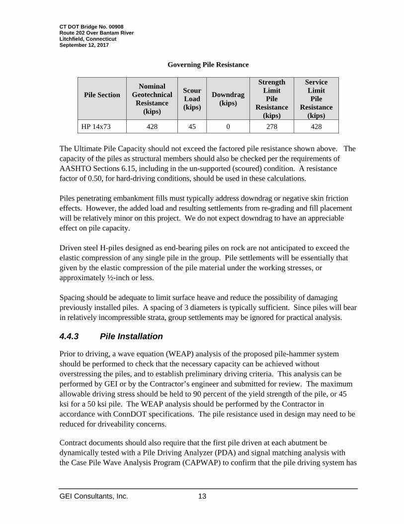
Governing Pile Resistance
Pile Section Nominal
Geotechnical Resistance
(kips)
Scour Load (kips)
Downdrag (kips)
Strength Limit Pile
Resistance (kips)
Service Limit Pile
Resistance (kips)
HP 14x73 428 45 0 278 428
The Ultimate Pile Capacity should not exceed the factored pile resistance shown above. The capacity of the piles as structural members should also be checked per the requirements of AASHTO Sections 6.15, including in the un-supported (scoured) condition. A resistance factor of 0.50, for hard-driving conditions, should be used in these calculations. Piles penetrating embankment fills must typically address downdrag or negative skin friction effects. However, the added load and resulting settlements from re-grading and fill placement will be relatively minor on this project. We do not expect downdrag to have an appreciable effect on pile capacity. Driven steel H-piles designed as end-bearing piles on rock are not anticipated to exceed the elastic compression of any single pile in the group. Pile settlements will be essentially that given by the elastic compression of the pile material under the working stresses, or approximately ½-inch or less. Spacing should be adequate to limit surface heave and reduce the possibility of damaging previously installed piles. A spacing of 3 diameters is typically sufficient. Since piles will bear in relatively incompressible strata, group settlements may be ignored for practical analysis. 4.4.3 Pile Installation
Prior to driving, a wave equation (WEAP) analysis of the proposed pile-hammer system should be performed to check that the necessary capacity can be achieved without overstressing the piles, and to establish preliminary driving criteria. This analysis can be performed by GEI or by the Contractor’s engineer and submitted for review. The maximum allowable driving stress should be held to 90 percent of the yield strength of the pile, or 45 ksi for a 50 ksi pile. The WEAP analysis should be performed by the Contractor in accordance with ConnDOT specifications. The pile resistance used in design may need to be reduced for driveability concerns.
Contract documents should also require that the first pile driven at each abutment be dynamically tested with a Pile Driving Analyzer (PDA) and signal matching analysis with the Case Pile Wave Analysis Program (CAPWAP) to confirm that the pile driving system has
CT DOT Bridge No. 00908 Route 202 Over Bantam River Litchfield, Connecticut September 12, 2017
GEI Consultants, Inc. 14
adequately driven the pile to the required capacity. The primary purpose of the testing is to assess pile stresses and the ability of the piles to penetrate the bedrock surface. Piles should be driven to the ultimate capacity shown on the plans. Final acceptance of the proposed pile hammer and derivation of driving criteria should be based upon the field performance and results of the dynamic pile testing. Once a pile driving system is shown to be acceptable based on the field performance and the results of the dynamic pile testing, the same driving system should be used for the duration of production pile installation. If the Contractor elects to use a different hammer or makes any other changes to the pile driving system, the Contractor should be responsible for providing additional dynamic pile testing for the new pile driving system. 4.4.4 Lateral Response
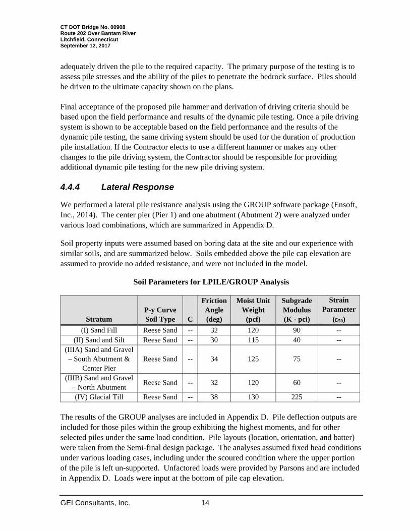
We performed a lateral pile resistance analysis using the GROUP software package (Ensoft, Inc., 2014). The center pier (Pier 1) and one abutment (Abutment 2) were analyzed under various load combinations, which are summarized in Appendix D.
Soil property inputs were assumed based on boring data at the site and our experience with similar soils, and are summarized below. Soils embedded above the pile cap elevation are assumed to provide no added resistance, and were not included in the model.
Soil Parameters for LPILE/GROUP Analysis
Stratum P-y Curve Soil Type C
Friction Angle (deg)
Moist Unit Weight
(pcf)
Subgrade Modulus (K - pci)
Strain Parameter
(50)
(I) Sand Fill Reese Sand -- 32 120 90 -- (II) Sand and Silt Reese Sand -- 30 115 40 --
(IIIA) Sand and Gravel – South Abutment &
Center Pier Reese Sand -- 34 125 75 --
(IIIB) Sand and Gravel – North Abutment
Reese Sand -- 32 120 60 --
(IV) Glacial Till Reese Sand -- 38 130 225 --
The results of the GROUP analyses are included in Appendix D. Pile deflection outputs are included for those piles within the group exhibiting the highest moments, and for other selected piles under the same load condition. Pile layouts (location, orientation, and batter) were taken from the Semi-final design package. The analyses assumed fixed head conditions under various loading cases, including under the scoured condition where the upper portion of the pile is left un-supported. Unfactored loads were provided by Parsons and are included in Appendix D. Loads were input at the bottom of pile cap elevation.
CT DOT Bridge No. 00908 Route 202 Over Bantam River Litchfield, Connecticut September 12, 2017
GEI Consultants, Inc. 15
The maximum deflection estimate is less than ¼-inch for all cases analyzed, well within acceptable tolerance. The maximum moments within the piles shown in Table D3 also appear to be within acceptable limits; however, this should be verified as part of the pile structural capacity check.
4.5 Lateral Earth Pressures
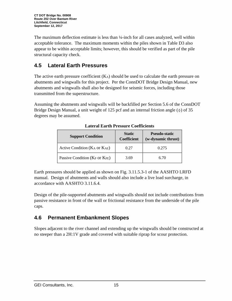
The active earth pressure coefficient (KA) should be used to calculate the earth pressure on abutments and wingwalls for this project. Per the ConnDOT Bridge Design Manual, new abutments and wingwalls shall also be designed for seismic forces, including those transmitted from the superstructure.
Assuming the abutments and wingwalls will be backfilled per Section 5.6 of the ConnDOT Bridge Design Manual, a unit weight of 125 pcf and an internal friction angle (ϕ) of 35 degrees may be assumed.
Lateral Earth Pressure Coefficients
Support Condition Static
Coefficient Pseudo-static
(w-dynamic thrust)
Active Condition (KA or KAE) 0.27 0.275
Passive Condition (KP or KPE) 3.69 6.70
Earth pressures should be applied as shown on Fig. 3.11.5.3-1 of the AASHTO LRFD manual. Design of abutments and walls should also include a live load surcharge, in accordance with AASHTO 3.11.6.4. Design of the pile-supported abutments and wingwalls should not include contributions from passive resistance in front of the wall or frictional resistance from the underside of the pile caps. 4.6 Permanent Embankment Slopes
Slopes adjacent to the river channel and extending up the wingwalls should be constructed at no steeper than a 2H:1V grade and covered with suitable riprap for scour protection.

CT DOT Bridge No. 00908 Route 202 Over Bantam River Litchfield, Connecticut September 12, 2017
GEI Consultants, Inc. 16
5. Construction Recommendations
5.1 Excavation and Dewatering
At a minimum, all excavations should be made in accordance with Occupational Safety and Health Administration (OSHA) standards.
Excavations for new construction will require temporary excavation support, in order to maintain one-way traffic during staged operations, and are expected to occur below the groundwater table (abutments) and stream level (center pier). All excavations should be conducted in the dry. We recommend that cofferdams be specified at each abutment and for the center pier. The Structure Excavation-Earth (Excluding Cofferdam and Dewatering) and Cofferdam and Dewatering Items should be incorporated into the bidding documents.
Any necessary excavation support systems/cofferdams should be designed by a Connecticut-registered professional engineer experienced in design of such elements. The engineer should be engaged by the contractor and submit the designs for review before installation. We caution that sheet piles near the abutments will require special shoes and/or pre-drilling to penetrate significant cobbles or boulders encountered below the roadway surface in several of our borings.
5.2 Protection of Existing Structures
There is a business (AmeriGas) approximately 150 feet north of the bridge that maintains large compressed gas tanks set on elevated concrete piers. Given the sensitive nature of the material and the vessels it is stored in, we recommend conducting vibration monitoring during pile installation near the north abutment. The business owner, and likely the vessel manufacturer as well, should be consulted regarding particulars of the vibration monitoring, principally the maximum allowable vibration. The independent monitoring consultant, to be hired by the contractor, shall determine the maximum allowable permissible vibrations. 5.3 Subgrade Preparation
Plans at this time show all substructure elements will be founded on piles. On subgrades where new fill will be placed, loose or disturbed soil should be removed and the subgrade should be prepared in accordance with ConnDOT specifications. If loose or organic-laden alluvial soils similar to those encountered in some of our borings are left in place, some settlement of the approach slabs and downdrag loading of the piles may occur. All subgrades should also be free of frost.

CT DOT Bridge No. 00908 Route 202 Over Bantam River Litchfield, Connecticut September 12, 2017
GEI Consultants, Inc. 17
Pervious Structure Backfill should be placed behind abutments and wingwalls to the limits described in Section 5.6 of the ConnDOT Bridge Design Manual and compacted in accordance with the Standard Specifications.
CT DOT Bridge No. 00908 Route 202 Over Bantam River Litchfield, Connecticut September 12, 2017
GEI Consultants, Inc. 18
6. Limitations
Our recommendations are based on the project information provided to us at the time of this report and may require modification if there are any changes in the nature, design, or location of the proposed construction. We recommend that GEI be engaged to review the final plans and specifications to judge whether changes in the project affect the validity of our recommendations and whether our recommendations have been properly implemented in the design.
The recommendations in this report are based in part on the data obtained from the borings. The nature and extent of variations between borings may not become evident until construction. If variations from the anticipated conditions are encountered, it may be necessary to revise the recommendations in this report. Therefore, we recommend that GEI be engaged to make site visits during construction to: a) check that the subsurface conditions exposed during construction are in general conformance with our design assumptions and b) ascertain that, in general, the geotechnical aspects of the work are being performed in compliance with the contract documents.
Our professional services for this project have been performed in accordance with generally accepted engineering practices; no warranty, express or implied, is made.
CT DOT Bridge No. 00908 Route 202 Over Bantam River Litchfield, Connecticut September 12, 2017
GEI Consultants, Inc. 19
7. References
AASHTO (2012). AASHTO LRFD Bridge Design Specifications, 6th Edition, with interim revisions through 2013.
Connecticut Department of Transportation (ConnDOT). Geotechnical Engineering Manual, 2005 Edition, revised February 2009.
Connecticut Department of Transportation (ConnDOT). Bridge Design Manual, 2003 edition with (up to) 2011 revisions.
Connecticut Department of Transportation (ConnDOT). Standard Specifications for Roads, Bridges, and Incidental Construction, Form 816, 2004 merged with 2013 Supplemental Specifications.
BL Companies (2010). Rehabilitation Study Report: Bridge No. 00908 in Litchfield, Route 202 over Bantam River.
Rodgers, John (1985). Bedrock Geological Map of Connecticut, Connecticut Geological and Natural History Survey in cooperation with U.S. Geological Survey, U.S. Department of the Interior.
State of Connecticut Department of Environmental Protection (DEP) (2010). Quaternary Geology, Litchfield, Connecticut.
CT DOT Bridge No. 00908 Route 202 over Bantam River Litchfield, Connecticut September 12, 2017
GEI Consultants, Inc.
Appendix A
Figures and Tables

SITE
SITE LOCUS
CT DOT BRIDGE NO. 00908
U.S. ROUTE 202 OVER BANTAM RIVER
LITCHFIELD, CONNECTICUT
PARSONS TRANSPORTATION GROUP, INC.
BOSTON, MASSACHUSETTS
0
SCALE, FEET
2000 4000
SOURCE:
U.S.G.S. TOPOGRAPHIC MAP ELMIRA, NY 1969, CREATED WITH TOPO!
® ©2004 NATIONAL GEOGRAPHIC (www.nationalgeographic.com/topo)
October 2013 Figure 1Project 1328830-1000
I:\Project\Parsons Transportation Gropu, Inc\1328830\Torrington Site-Loc.dwg
B-1B
B-1A
B-2
B-3B-1
B-4
B-5
---- H:\TECH\project\Parsons Transportation Group\Route 202 Over Bantam River\Drawings\FIG 2 - BLP.dwg - 6/3/2014
Fig. 2
U.S. Route 202 Over Bantam River
CT DOT Bridge No. 00908
Litchfield, Connecticut
Parsons Transportation Group
Boston, Massachusetts
BORING LOCATION PLAN
May 2014Project 1328830
Consultants
NOTES:
1. BORING LOCATIONS AND BASE PLAN DRAWING BASED ON
SURVEY PREPARED BY CONNECTICUT DOT.
LEGEND:
SOIL BORING
SCALE:
0 50 100
1:50
B-1
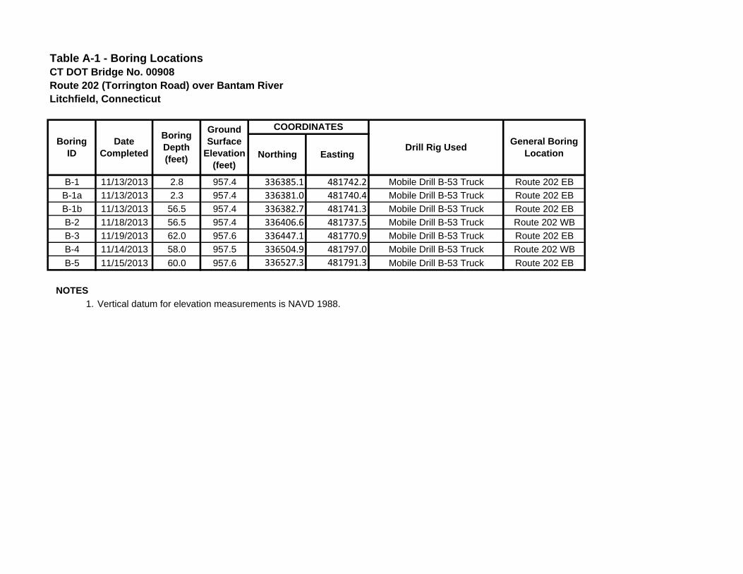
B-1 11/13/2013 2.8 957.4 336385.1 481742.2 Mobile Drill B-53 Truck Route 202 EB
B-1a 11/13/2013 2.3 957.4 336381.0 481740.4 Mobile Drill B-53 Truck Route 202 EB
B-1b 11/13/2013 56.5 957.4 336382.7 481741.3 Mobile Drill B-53 Truck Route 202 EB
B-2 11/18/2013 56.5 957.4 336406.6 481737.5 Mobile Drill B-53 Truck Route 202 WB
B-3 11/19/2013 62.0 957.6 336447.1 481770.9 Mobile Drill B-53 Truck Route 202 EB
B-4 11/14/2013 58.0 957.5 336504.9 481797.0 Mobile Drill B-53 Truck Route 202 WB
B-5 11/15/2013 60.0 957.6 336527.3 481791.3 Mobile Drill B-53 Truck Route 202 EB
NOTES
1. Vertical datum for elevation measurements is NAVD 1988.
General BoringLocationNorthing Easting
Table A-1 - Boring LocationsCT DOT Bridge No. 00908Route 202 (Torrington Road) over Bantam RiverLitchfield, Connecticut
BoringID
DateCompleted
BoringDepth(feet)
Ground Surface
Elevation(feet)
COORDINATES
Drill Rig Used

B-1 957.4 1.4 956.0 -- -- -- -- -- -- -- -- -- -- -- -- -- -- --
B-1a 957.4 1.3 956.1 -- -- -- -- -- -- -- -- -- -- -- -- -- -- --
B-1b 957.4 1.3 956.1 4.7 6.0 951.4 5.3 11.3 946.1 9.8 21.1 936.3 25.4 -- -- -- 46.5 910.9
B-2 957.4 4.0 953.4 3.1 7.1 950.3 3.7 10.8 946.6 14.2 25.0 932.4 19.5 -- -- -- 44.5 912.9
B-3 957.6 -- -- -- -- -- -- 11.0 946.6 19.9 30.9 926.7 21.1 -- -- -- 52.0 905.6
B-4 957.5 1.6 955.9 6.4 8 949.5 3.4 11.4 946.1 34.6 46.0 911.5 2.0 -- -- -- 48.0 909.5
B-5 957.6 1.8 955.8 3.4 5.2 952.4 5.2 10.4 947.2 35.5 -- -- -- 45.9 911.7 4.1 50.0 907.6
NOTES
1. Vertical datum for elevation measurements is NAVD 1988.
2 "--" indicates stratum not encountered
Depthto Top (feet)
Elevation(feet)
Depthto Top (feet)
Elevation(feet)
Thickness(feet)
Depthto Top (feet)
Elevation(feet)
WEATHERED BEDROCK
Thickness(feet)
III - SAND & GRAVEL
Depthto Top (feet)
Elevation(feet)
Thickness(feet)
IV - GLACIAL TILL
Table A-2 - Exploration Data CT DOT Bridge No. 00908Route 202 (Torrington Road) over Bantam RiverLitchfield, Connecticut
BoringID
Ground Surface
Elevation
SUBSURFACE STRATA
Depthto Top (feet)
Elevation(feet)
Thickness(feet)
Depthto Top (feet)
Elevation(feet)
Thickness(feet)
BEDROCKI - FILL II - ALLUVIUM
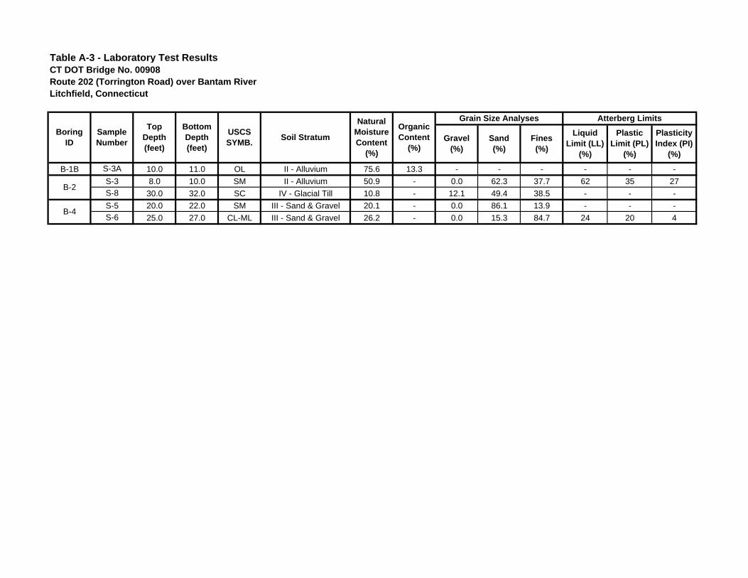
B-1B S-3A 10.0 11.0 OL II - Alluvium 75.6 13.3 - - - - - -
S-3 8.0 10.0 SM II - Alluvium 50.9 - 0.0 62.3 37.7 62 35 27
S-8 30.0 32.0 SC IV - Glacial Till 10.8 - 12.1 49.4 38.5 - - -
S-5 20.0 22.0 SM III - Sand & Gravel 20.1 - 0.0 86.1 13.9 - - -
S-6 25.0 27.0 CL-ML III - Sand & Gravel 26.2 - 0.0 15.3 84.7 24 20 4B-4
B-2
Atterberg Limits
Liquid Limit (LL)
(%)
Plastic Limit (PL)
(%)
PlasticityIndex (PI)
(%)
Table A-3 - Laboratory Test ResultsCT DOT Bridge No. 00908Route 202 (Torrington Road) over Bantam RiverLitchfield, Connecticut
BoringID
SampleNumber
TopDepth(feet)
BottomDepth(feet)
Soil StratumOrganicContent
(%)
USCSSYMB.
NaturalMoistureContent
(%)
Grain Size Analyses
Gravel(%)
Sand(%)
Fines(%)

Table A-4. Corrected Standard Penetration Test N-ValuesCTDOT Bridge No. 00908Route 202 Over Bantam RiverLitchfield, Connecticut
SOILBORING
SAMPLENO.
AVGDEPTH(FT)
0‐6" 6‐12" 12‐18" 18‐24"FIELD
N VALUE(blows/ft)
N60
(blows/ft)
Estimatedσv' (psf)
CNN1,60
(blows/ft)INTERPRETEDSTRATUM
B‐1 S1 2.5 14 18 100 118 118 313 1.62 100 I. FILLS1 5 13 20 26 31 46 46 625 1.39 64 I. FILLS2 7 5 3 4 2 7 7 800 1.31 9 II. ALLUVIUMS3A 10.5 12 14 28 28 1019 1.23 34 II. ALLUVIUMS3B 11.5 10 14 20 20 1082 1.21 24 III ‐ SAND AND GRAVELS4 16 10 11 65 24 76 76 1364 1.13 86 III ‐ SAND AND GRAVELS5A 20.5 10 12 24 24 1645 1.07 26 III ‐ SAND AND GRAVELS5B 21.5 30 45 60 60 1708 1.05 63 IV. GLACIAL TILLS6 26 13 15 21 40 36 36 1990 1.00 36 IV. GLACIAL TILLS7 31 22 25 37 20 62 62 2303 0.95 59 IV. GLACIAL TILLS8 36 10 8 7 10 15 15 2616 0.91 14 IV. GLACIAL TILLS9 41 6 7 12 19 19 19 2929 0.87 17 IV. GLACIAL TILLS10 45.25 100 100 100 3195 0.85 100 IV. GLACIAL TILLS1 5 8 4 5 6 9 9 625 1.39 13 I. FILLS2A 6.5 16 13 26 26 813 1.30 34 I. FILLS2B 7.5 5 6 10 10 938 1.26 13 II. ALLUVIUMS3 9 2 2 7 16 9 9 1100 1.20 11 II. ALLUVIUMS4A 11 22 18 36 36 1225 1.17 42 II. ALLUVIUMS4B 11 13 14 26 26 1225 1.17 30 III ‐ SAND AND GRAVELS5 16 10 7 12 13 19 19 1538 1.09 21 III ‐ SAND AND GRAVELS6 21 9 32 24 19 56 56 1851 1.03 58 III ‐ SAND AND GRAVELS7 26 11 13 16 19 29 29 2164 0.98 28 IV. GLACIAL TILLS8 31 28 29 14 15 43 43 2477 0.93 40 IV. GLACIAL TILLS9 36 21 22 22 34 44 44 2790 0.89 39 IV. GLACIAL TILLS10 41 23 24 30 32 54 54 3103 0.85 46 IV. GLACIAL TILLS1 12 24 18 14 15 32 32 1406 1.12 36 III ‐ SAND AND GRAVELS2 14 50 13 14 15 26 26 1532 1.09 28 III ‐ SAND AND GRAVELS3 16 16 14 14 11 28 28 1657 1.06 30 III ‐ SAND AND GRAVELS4 21 14 10 10 10 20 20 1970 1.01 20 III ‐ SAND AND GRAVELS5 26 12 35 43 38 78 78 2283 0.96 75 III ‐ SAND AND GRAVELS6A 31 24 48 48 2596 0.91 44 III ‐ SAND AND GRAVELS6B 31 86 61 50 122 122 2596 0.91 100 IV. GLACIAL TILLS7 36 33 75 99 100 174 174 2909 0.88 100 IV. GLACIAL TILLS8 41 37 37 35 63 72 72 3222 0.84 61 IV. GLACIAL TILLS9 45.5 53 100 100 100 3504 0.81 100 IV. GLACIAL TILLS10 50.25 100 100 100 3801 0.79 100 IV. GLACIAL TILLS1 5 18 25 70 37 95 95 625 1.39 100 I. FILLS2 9 4 4 5 6 9 9 1109 1.20 11 II. ALLUVIUMS3A 11 9 9 7 16 16 1235 1.16 19 II. ALLUVIUMS3B 11 13 26 26 1235 1.16 30 III ‐ SAND AND GRAVELS4 16 5 5 8 13 10 10 1548 1.09 11 III ‐ SANDS5 21 4 4 7 6 11 11 1861 1.03 11 III ‐ SANDS6 26 1 2 2 3 4 4 2174 0.97 4 III ‐ SILTS7A 31 2 4 4 2487 0.93 4 III ‐ SANDS7B 31 8 22 21 30 30 2487 0.93 28 III ‐ SAND AND GRAVELS8 36 6 6 6 6 12 12 2800 0.89 11 III ‐ SAND AND GRAVELS9 41 13 20 28 45 48 48 3113 0.85 41 III ‐ SAND AND GRAVEL
S10A 46 22 17 34 34 3426 0.82 28 III ‐ SAND AND GRAVELS10B 46 17 18 34 34 3426 0.82 28 IV ‐ GLACIAL TILLS1 3 9 8 8 14 16 16 360 1.58 25 I. FILLS2A 4.5 3 4 8 8 540 1.44 12 I. FILLS2B 5.5 2 2 4 4 660 1.37 5 II. ALLUVIUMS3 7 3 5 7 8 12 12 840 1.29 16 II. ALLUVIUMS4A 10.5 6 12 12 1179 1.18 14 II. ALLUVIUMS4B 11.5 22 15 8 30 30 1236 1.16 35 III ‐ SAND AND GRAVELS5 16 3 6 7 8 13 13 1496 1.10 14 III ‐ SANDS6 21 3 2 3 5 5 5 1784 1.04 5 III ‐ SANDS7 26 5 5 5 5 10 10 2072 0.99 10 III ‐ SANDS8 31 4 4 5 6 9 9 2360 0.95 9 III ‐ SANDS9 36 4 4 6 7 10 10 2648 0.91 9 III ‐ SANDS10 41 8 5 4 5 9 9 2936 0.87 8 III ‐ SANDS11 46 23 22 19 55 41 41 3224 0.84 35 III ‐ SAND AND GRAVEL
B‐5
B‐4
BLOWCOUNTS
B‐1b
B‐2
B‐3

CT DOT Bridge No. 00908 Route 202 over Bantam River Litchfield, Connecticut September 12, 2017
GEI Consultants, Inc.
Appendix B
Boring Logs
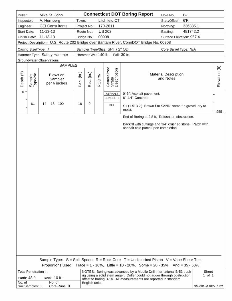
14 18 100 16 9
ASPHALT
CONCRETE
FILLS1
0'-6": Asphalt pavement.6"-1.4': Concrete.
S1 (1.5'-3.2'): Brown f-m SAND, some f-c gravel, dry tomoist.
End of Boring at 2.8 ft. Refusal on obstruction.
Backfill with cuttings and 3/4" crushed stone. Patch withasphalt cold patch upon completion.
Blows onSampler
per 6 inchesP
en.
(in.)
Rec
. (in
.)
Dep
th (
ft)
0
Project No.: 170-2811
Ele
vatio
n (f
t)
955
Hammer Wt.: 140 lb
Town: Litchfield,CT
No. ofCore Runs: 0
Inspector: A. Hernberg
Earth: 48 ft. Rock: 10 ft.
Bridge No.: 00908
Sampler Type/Size: SPT / 2" ODCasing Size/Type: /
RQ
D %
Engineer: GEI Consultants
Core Barrel Type: N/A
No. ofSoil Samples: 1
Total Penetration in
Fall: 30 in.
Project Description: U.S. Route 202 Bridge over Bantam River, ConnDOT Bridge No. 00908
Gen
eral
ized
Str
ata
Des
crip
tion
Route No.: US 202
NOTES: Boring was advanced by a Mobile Drill International B-53 truckrig using a solid stem auger. Driller could not auger through obstruction;offset to boring B-1a. All measurements are reported in standardEnglish units.
Sample Type: S = Split Spoon R = Rock Core T = Undisturbed Piston V = Vane Shear Test
Proportions Used: Trace = 1 - 10%, Little = 10 - 20%, Some = 20 - 35%, And = 35 - 50%
Hole No.: B-1
Sheet1 of 1
SAMPLES
Connecticut DOT Boring Report
SM-001-M REV. 1/02
Stat./Offset: 6'R
Groundwater Observations:
Northing: 336385.1
Easting: 481742.2
Surface Elevation: 957.4
Driller: Mike St. John
Start Date: 11-13-13
Finish Date: 11-13-13
Sam
ple
Typ
e/N
o. Material Descriptionand Notes
Hammer Type: Safety Hammer
ASPHALT
CONCRETE
FILL
0'-6": Asphalt pavement.6"-1.3': Concrete.
No sampling.
End of Boring at 2.3 ft. Refusal on obstruction.
Backfill with cuttings and 3/4" crushed stone. Patch withasphalt cold patch upon completion.
Blows onSampler
per 6 inchesP
en.
(in.)
Rec
. (in
.)
Dep
th (
ft)
0
Project No.: 170-2811
Ele
vatio
n (f
t)
Hammer Wt.:
Town: Litchfield,CT
No. ofCore Runs: 0
Inspector: A. Hernberg
Earth: 48 ft. Rock: 10 ft.
Bridge No.: 00908
Sampler Type/Size: /Casing Size/Type: /
RQ
D %
Engineer: GEI Consultants
Core Barrel Type: N/A
No. ofSoil Samples: 0
Total Penetration in
Fall:
Project Description: U.S. Route 202 Bridge over Bantam River, ConnDOT Bridge No. 00908
Gen
eral
ized
Str
ata
Des
crip
tion
Route No.: US 202
NOTES: Boring was advanced by a Mobile Drill International B-53 truckrig using a solid stem auger. Driller could not auger through obstruction;offset to boring B-1b. All measurements are reported in standardEnglish units.
Sample Type: S = Split Spoon R = Rock Core T = Undisturbed Piston V = Vane Shear Test
Proportions Used: Trace = 1 - 10%, Little = 10 - 20%, Some = 20 - 35%, And = 35 - 50%
Hole No.: B-1a
Sheet1 of 1
SAMPLES
Connecticut DOT Boring Report
SM-001-M REV. 1/02
Stat./Offset: 6'R
Groundwater Observations:
Northing: 336381.0
Easting: 481740.4
Surface Elevation: 957.4
Driller: Mike St. John
Start Date: 11-13-13
Finish Date: 11-13-13
Sam
ple
Typ
e/N
o. Material Descriptionand Notes
Hammer Type:

13 20 26 31
5 3 4 2
12 14 10 14
10 11 65 24
24
24
24
24
12
11
17
24
ASPHALT
CONCRETE
FILL
ALLUVIUM
SANDAND
GRAVEL
S1
S2
S3
S4
0'-6": Asphalt pavement6"-1.25': Concrete
S1 (4'-6'): Brown f-m SAND and f-c gravel, trace silt,moist, quartz cobble in sample.
Difficult augering noted between 5 and 6 feet. Rockfragments (>2") in cuttings.S2 (6'-8'): Gray to brown f-c SAND, some f-m gravel,some silt, trace fine roots, dry to moist.
S3A (10'-11.3'): Gray to brown ORGANIC SILT, manyroots and wood fibers (13.3% organic content), little fsand, moist.S3B (11.3'-12'): Gray f-c SAND and f-c gravel, moist.
S4 (15'-17'): Gray to brown f-c SAND, some f-c gravel,trace silt, wet.
Blows onSampler
per 6 inchesP
en.
(in.)
Rec
. (in
.)
Dep
th (
ft)
0
5
10
15
20
Project No.: 170-2811
Ele
vatio
n (f
t)
955
950
945
940
Hammer Wt.: 140 lb
Town: Litchfield,CT
No. ofCore Runs: 2
Inspector: A. Hernberg
Earth: 46.5 ft. Rock: 10 ft.
Bridge No.: 00908
Sampler Type/Size: SPT / 2" ODCasing Size/Type: 2.5" ID / 3.0" OD
RQ
D %
Engineer: GEI Consultants
Core Barrel Type: NX
No. ofSoil Samples: 12
Total Penetration in
Fall: 30 in.
Project Description: U.S. Route 202 Bridge over Bantam River, ConnDOT Bridge No. 00908
Gen
eral
ized
Str
ata
Des
crip
tion
Route No.: US 202
NOTES: Boring was advanced by a Mobile Drill International B-53 truckrig using a solid stem auger to 15 ft below grade. After advancement to15 ft, boring was advanced using the drive and wash method with 3"casing and water as the drilling fluid. All measurements are reported instandard English units.
Sample Type: S = Split Spoon R = Rock Core T = Undisturbed Piston V = Vane Shear Test
Proportions Used: Trace = 1 - 10%, Little = 10 - 20%, Some = 20 - 35%, And = 35 - 50%
Hole No.: B-1b
Sheet1 of 3
SAMPLES
Connecticut DOT Boring Report
SM-001-M REV. 1/02
Stat./Offset: 6'R
Groundwater Observations: 5.8ft. Measured prior to casing install
Northing: 336382.7
Easting: 481741.3
Surface Elevation: 957.4
Driller: Mike St. John
Start Date: 11-13-13
Finish Date: 11-13-13
Sam
ple
Typ
e/N
o. Material Descriptionand Notes
Hammer Type: Safety Hammer

10 12 30 45
13 15 21 40
22 25 37 20
10 8 7 10
24
24
24
24
14
10
10
10
GLACIALTILL
S5
S6
S7
S8
S5A (20'-21.1'): Gray f-c SAND, little f-m gravel, trace silt,wet.
S5B (21.1'-22'): Gray SILT and f-m sand, some f-c gravel,moist.
S6 (25'-27'): Gray SILT and f-m sand, some f-m gravel,moist.
S7 (30'-32'): Gray SILT and f-m sand, little f-c gravel,moist.
S8 (35'-37'): Gray SILT and f-m sand, little f-m gravel,moist.
Blows onSampler
per 6 inchesP
en.
(in.)
Rec
. (in
.)
Dep
th (
ft)
20
25
30
35
40
Project No.: 170-2811
Ele
vatio
n (f
t)
935
930
925
920
Hammer Wt.: 140 lb
Town: Litchfield,CT
No. ofCore Runs: 2
Inspector: A. Hernberg
Earth: 46.5 ft. Rock: 10 ft.
Bridge No.: 00908
Sampler Type/Size: SPT / 2" ODCasing Size/Type: 2.5" ID / 3.0" OD
RQ
D %
Engineer: GEI Consultants
Core Barrel Type: NX
No. ofSoil Samples: 12
Total Penetration in
Fall: 30 in.
Project Description: U.S. Route 202 Bridge over Bantam River, ConnDOT Bridge No. 00908
Gen
eral
ized
Str
ata
Des
crip
tion
Route No.: US 202
NOTES: Boring was advanced by a Mobile Drill International B-53 truckrig using a solid stem auger to 15 ft below grade. After advancement to15 ft, boring was advanced using the drive and wash method with 3"casing and water as the drilling fluid. All measurements are reported instandard English units.
Sample Type: S = Split Spoon R = Rock Core T = Undisturbed Piston V = Vane Shear Test
Proportions Used: Trace = 1 - 10%, Little = 10 - 20%, Some = 20 - 35%, And = 35 - 50%
Hole No.: B-1b
Sheet2 of 3
SAMPLES
Connecticut DOT Boring Report
SM-001-M REV. 1/02
Stat./Offset: 6'R
Groundwater Observations: 5.8ft. Measured prior to casing install
Northing: 336382.7
Easting: 481741.3
Surface Elevation: 957.4
Driller: Mike St. John
Start Date: 11-13-13
Finish Date: 11-13-13
Sam
ple
Typ
e/N
o. Material Descriptionand Notes
Hammer Type: Safety Hammer
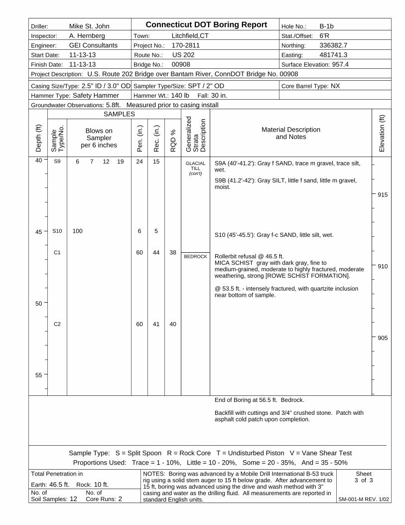
6 7 12 19
100
24
6
60
60
15
5
44
41
38
40
GLACIALTILL
(con't)
BEDROCK
S9
S10
C1
C2
S9A (40'-41.2'): Gray f SAND, trace m gravel, trace silt,wet.
S9B (41.2'-42'): Gray SILT, little f sand, little m gravel,moist.
S10 (45'-45.5'): Gray f-c SAND, little silt, wet.
Rollerbit refusal @ 46.5 ft.MICA SCHIST gray with dark gray, fine tomedium-grained, moderate to highly fractured, moderateweathering, strong [ROWE SCHIST FORMATION].
@ 53.5 ft. - intensely fractured, with quartzite inclusionnear bottom of sample.
End of Boring at 56.5 ft. Bedrock.
Backfill with cuttings and 3/4" crushed stone. Patch withasphalt cold patch upon completion.
Blows onSampler
per 6 inchesP
en.
(in.)
Rec
. (in
.)
Dep
th (
ft)
40
45
50
55
Project No.: 170-2811
Ele
vatio
n (f
t)
915
910
905
Hammer Wt.: 140 lb
Town: Litchfield,CT
No. ofCore Runs: 2
Inspector: A. Hernberg
Earth: 46.5 ft. Rock: 10 ft.
Bridge No.: 00908
Sampler Type/Size: SPT / 2" ODCasing Size/Type: 2.5" ID / 3.0" OD
RQ
D %
Engineer: GEI Consultants
Core Barrel Type: NX
No. ofSoil Samples: 12
Total Penetration in
Fall: 30 in.
Project Description: U.S. Route 202 Bridge over Bantam River, ConnDOT Bridge No. 00908
Gen
eral
ized
Str
ata
Des
crip
tion
Route No.: US 202
NOTES: Boring was advanced by a Mobile Drill International B-53 truckrig using a solid stem auger to 15 ft below grade. After advancement to15 ft, boring was advanced using the drive and wash method with 3"casing and water as the drilling fluid. All measurements are reported instandard English units.
Sample Type: S = Split Spoon R = Rock Core T = Undisturbed Piston V = Vane Shear Test
Proportions Used: Trace = 1 - 10%, Little = 10 - 20%, Some = 20 - 35%, And = 35 - 50%
Hole No.: B-1b
Sheet3 of 3
SAMPLES
Connecticut DOT Boring Report
SM-001-M REV. 1/02
Stat./Offset: 6'R
Groundwater Observations: 5.8ft. Measured prior to casing install
Northing: 336382.7
Easting: 481741.3
Surface Elevation: 957.4
Driller: Mike St. John
Start Date: 11-13-13
Finish Date: 11-13-13
Sam
ple
Typ
e/N
o. Material Descriptionand Notes
Hammer Type: Safety Hammer
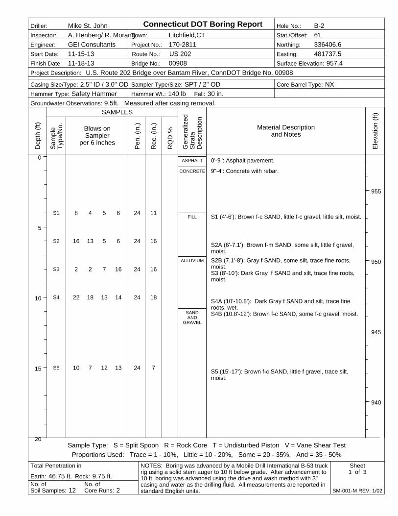
8 4 5 6
16 13 5 6
2 2 7 16
22 18 13 14
10 7 12 13
24
24
24
24
24
11
16
16
18
7
ASPHALT
CONCRETE
FILL
ALLUVIUM
SANDAND
GRAVEL
S1
S2
S3
S4
S5
0'-9": Asphalt pavement.
9"-4': Concrete with rebar.
S1 (4'-6'): Brown f-c SAND, little f-c gravel, little silt, moist.
S2A (6'-7.1'): Brown f-m SAND, some silt, little f gravel,moist.
S2B (7.1'-8'): Gray f SAND, some silt, trace fine roots,moist.S3 (8'-10'): Dark Gray f SAND and silt, trace fine roots,moist.
S4A (10'-10.8'): Dark Gray f SAND and silt, trace fineroots, wet.S4B (10.8'-12'): Brown f-c SAND, some f-c gravel, moist.
S5 (15'-17'): Brown f-c SAND, little f gravel, trace silt,moist.
Blows onSampler
per 6 inchesP
en.
(in.)
Rec
. (in
.)
Dep
th (
ft)
0
5
10
15
20
Project No.: 170-2811
Ele
vatio
n (f
t)
955
950
945
940
Hammer Wt.: 140 lb
Town: Litchfield,CT
No. ofCore Runs: 2
Inspector: A. Henberg/ R. Morang
Earth: 46.75 ft. Rock: 9.75 ft.
Bridge No.: 00908
Sampler Type/Size: SPT / 2" ODCasing Size/Type: 2.5" ID / 3.0" OD
RQ
D %
Engineer: GEI Consultants
Core Barrel Type: NX
No. ofSoil Samples: 12
Total Penetration in
Fall: 30 in.
Project Description: U.S. Route 202 Bridge over Bantam River, ConnDOT Bridge No. 00908
Gen
eral
ized
Str
ata
Des
crip
tion
Route No.: US 202
NOTES: Boring was advanced by a Mobile Drill International B-53 truckrig using a solid stem auger to 10 ft below grade. After advancement to10 ft, boring was advanced using the drive and wash method with 3"casing and water as the drilling fluid. All measurements are reported instandard English units.
Sample Type: S = Split Spoon R = Rock Core T = Undisturbed Piston V = Vane Shear Test
Proportions Used: Trace = 1 - 10%, Little = 10 - 20%, Some = 20 - 35%, And = 35 - 50%
Hole No.: B-2
Sheet1 of 3
SAMPLES
Connecticut DOT Boring Report
SM-001-M REV. 1/02
Stat./Offset: 6'L
Groundwater Observations: 9.5ft. Measured after casing removal.
Northing: 336406.6
Easting: 481737.5
Surface Elevation: 957.4
Driller: Mike St. John
Start Date: 11-15-13
Finish Date: 11-18-13
Sam
ple
Typ
e/N
o. Material Descriptionand Notes
Hammer Type: Safety Hammer

9 32 24 19
11 13 16 19
28 29 14 15
21 22 22 34
24
24
24
24
7
8
3
0
SANDAND
GRAVEL(con't)
GLACIALTILL
S6
S7
S8
S9
S6A (20'-21.8'): Gray to brown f-c GRAVEL and f-c sand,little silt, wet.
S6B (21.8'-22'): Gray f SAND and silt, little f gravel, moist.
S7 (25'-27'): Gray f-m SAND and silt, some f-m gravel,moist.
S8 (30'-32'): Gray f-m SAND and silt, little f-m gravel, wet.
S9 (35'-37'): No recovery.
Blows onSampler
per 6 inchesP
en.
(in.)
Rec
. (in
.)
Dep
th (
ft)
20
25
30
35
40
Project No.: 170-2811
Ele
vatio
n (f
t)
935
930
925
920
Hammer Wt.: 140 lb
Town: Litchfield,CT
No. ofCore Runs: 2
Inspector: A. Henberg/ R. Morang
Earth: 46.75 ft. Rock: 9.75 ft.
Bridge No.: 00908
Sampler Type/Size: SPT / 2" ODCasing Size/Type: 2.5" ID / 3.0" OD
RQ
D %
Engineer: GEI Consultants
Core Barrel Type: NX
No. ofSoil Samples: 12
Total Penetration in
Fall: 30 in.
Project Description: U.S. Route 202 Bridge over Bantam River, ConnDOT Bridge No. 00908
Gen
eral
ized
Str
ata
Des
crip
tion
Route No.: US 202
NOTES: Boring was advanced by a Mobile Drill International B-53 truckrig using a solid stem auger to 10 ft below grade. After advancement to10 ft, boring was advanced using the drive and wash method with 3"casing and water as the drilling fluid. All measurements are reported instandard English units.
Sample Type: S = Split Spoon R = Rock Core T = Undisturbed Piston V = Vane Shear Test
Proportions Used: Trace = 1 - 10%, Little = 10 - 20%, Some = 20 - 35%, And = 35 - 50%
Hole No.: B-2
Sheet2 of 3
SAMPLES
Connecticut DOT Boring Report
SM-001-M REV. 1/02
Stat./Offset: 6'L
Groundwater Observations: 9.5ft. Measured after casing removal.
Northing: 336406.6
Easting: 481737.5
Surface Elevation: 957.4
Driller: Mike St. John
Start Date: 11-15-13
Finish Date: 11-18-13
Sam
ple
Typ
e/N
o. Material Descriptionand Notes
Hammer Type: Safety Hammer
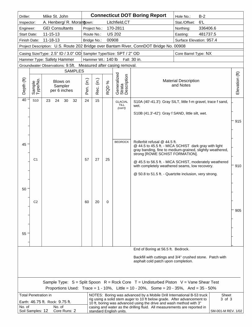
23 24 30 32 24
57
60
15
27
20
25
0
GLACIALTILL
(con't)
BEDROCK
S10
C1
C2
S10A (40'-41.3'): Gray SILT, little f-m gravel, trace f sand,wet.
S10B (41.3'-42'): Gray f SAND, little silt, wet.
Rollerbit refusal @ 44.5 ft.@ 44.5 to 45.5 ft. - MICA SCHIST dark gray with lightgray banding, fine to medium-grained, slightly weathered,strong [ROWE SCHIST FORMATION].
@ 45.5 to 56.5 ft. - MICA SCHIST, moderately weatheredwith completely weathered seams, low recovery.
@ 50.8 to 51.5 ft. - Quartzite inclusion, very strong.
End of Boring at 56.5 ft. Bedrock.
Backfill with cuttings and 3/4" crushed stone. Patch withasphalt cold patch upon completion.
Blows onSampler
per 6 inchesP
en.
(in.)
Rec
. (in
.)
Dep
th (
ft)
40
45
50
55
Project No.: 170-2811
Ele
vatio
n (f
t)
915
910
905
Hammer Wt.: 140 lb
Town: Litchfield,CT
No. ofCore Runs: 2
Inspector: A. Henberg/ R. Morang
Earth: 46.75 ft. Rock: 9.75 ft.
Bridge No.: 00908
Sampler Type/Size: SPT / 2" ODCasing Size/Type: 2.5" ID / 3.0" OD
RQ
D %
Engineer: GEI Consultants
Core Barrel Type: NX
No. ofSoil Samples: 12
Total Penetration in
Fall: 30 in.
Project Description: U.S. Route 202 Bridge over Bantam River, ConnDOT Bridge No. 00908
Gen
eral
ized
Str
ata
Des
crip
tion
Route No.: US 202
NOTES: Boring was advanced by a Mobile Drill International B-53 truckrig using a solid stem auger to 10 ft below grade. After advancement to10 ft, boring was advanced using the drive and wash method with 3"casing and water as the drilling fluid. All measurements are reported instandard English units.
Sample Type: S = Split Spoon R = Rock Core T = Undisturbed Piston V = Vane Shear Test
Proportions Used: Trace = 1 - 10%, Little = 10 - 20%, Some = 20 - 35%, And = 35 - 50%
Hole No.: B-2
Sheet3 of 3
SAMPLES
Connecticut DOT Boring Report
SM-001-M REV. 1/02
Stat./Offset: 6'L
Groundwater Observations: 9.5ft. Measured after casing removal.
Northing: 336406.6
Easting: 481737.5
Surface Elevation: 957.4
Driller: Mike St. John
Start Date: 11-15-13
Finish Date: 11-18-13
Sam
ple
Typ
e/N
o. Material Descriptionand Notes
Hammer Type: Safety Hammer
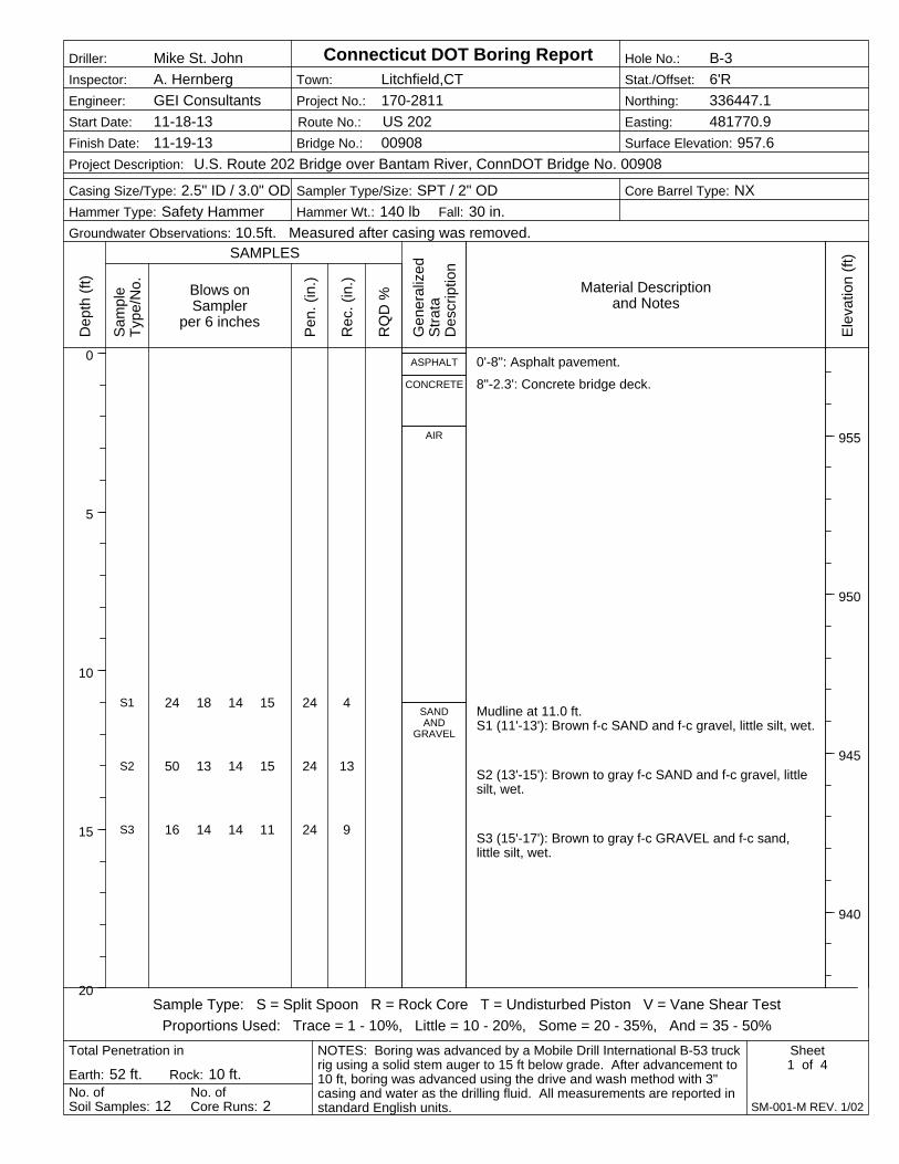
24 18 14 15
50 13 14 15
16 14 14 11
24
24
24
4
13
9
ASPHALT
CONCRETE
AIR
SANDAND
GRAVEL
S1
S2
S3
0'-8": Asphalt pavement.
8"-2.3': Concrete bridge deck.
Mudline at 11.0 ft.S1 (11'-13'): Brown f-c SAND and f-c gravel, little silt, wet.
S2 (13'-15'): Brown to gray f-c SAND and f-c gravel, littlesilt, wet.
S3 (15'-17'): Brown to gray f-c GRAVEL and f-c sand,little silt, wet.
Blows onSampler
per 6 inchesP
en.
(in.)
Rec
. (in
.)
Dep
th (
ft)
0
5
10
15
20
Project No.: 170-2811
Ele
vatio
n (f
t)
955
950
945
940
Hammer Wt.: 140 lb
Town: Litchfield,CT
No. ofCore Runs: 2
Inspector: A. Hernberg
Earth: 52 ft. Rock: 10 ft.
Bridge No.: 00908
Sampler Type/Size: SPT / 2" ODCasing Size/Type: 2.5" ID / 3.0" OD
RQ
D %
Engineer: GEI Consultants
Core Barrel Type: NX
No. ofSoil Samples: 12
Total Penetration in
Fall: 30 in.
Project Description: U.S. Route 202 Bridge over Bantam River, ConnDOT Bridge No. 00908
Gen
eral
ized
Str
ata
Des
crip
tion
Route No.: US 202
NOTES: Boring was advanced by a Mobile Drill International B-53 truckrig using a solid stem auger to 15 ft below grade. After advancement to10 ft, boring was advanced using the drive and wash method with 3"casing and water as the drilling fluid. All measurements are reported instandard English units.
Sample Type: S = Split Spoon R = Rock Core T = Undisturbed Piston V = Vane Shear Test
Proportions Used: Trace = 1 - 10%, Little = 10 - 20%, Some = 20 - 35%, And = 35 - 50%
Hole No.: B-3
Sheet1 of 4
SAMPLES
Connecticut DOT Boring Report
SM-001-M REV. 1/02
Stat./Offset: 6'R
Groundwater Observations: 10.5ft. Measured after casing was removed.
Northing: 336447.1
Easting: 481770.9
Surface Elevation: 957.6
Driller: Mike St. John
Start Date: 11-18-13
Finish Date: 11-19-13
Sam
ple
Typ
e/N
o. Material Descriptionand Notes
Hammer Type: Safety Hammer
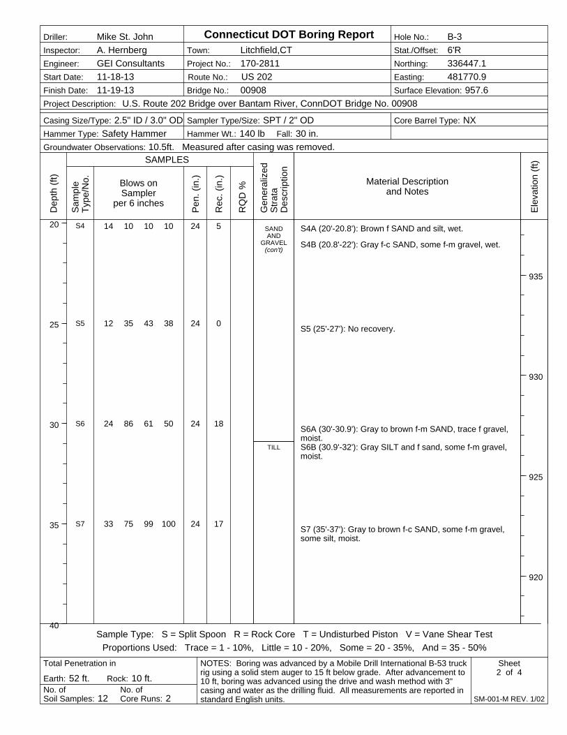
14 10 10 10
12 35 43 38
24 86 61 50
33 75 99 100
24
24
24
24
5
0
18
17
SANDAND
GRAVEL(con't)
TILL
S4
S5
S6
S7
S4A (20'-20.8'): Brown f SAND and silt, wet.
S4B (20.8'-22'): Gray f-c SAND, some f-m gravel, wet.
S5 (25'-27'): No recovery.
S6A (30'-30.9'): Gray to brown f-m SAND, trace f gravel,moist.S6B (30.9'-32'): Gray SILT and f sand, some f-m gravel,moist.
S7 (35'-37'): Gray to brown f-c SAND, some f-m gravel,some silt, moist.
Blows onSampler
per 6 inchesP
en.
(in.)
Rec
. (in
.)
Dep
th (
ft)
20
25
30
35
40
Project No.: 170-2811
Ele
vatio
n (f
t)
935
930
925
920
Hammer Wt.: 140 lb
Town: Litchfield,CT
No. ofCore Runs: 2
Inspector: A. Hernberg
Earth: 52 ft. Rock: 10 ft.
Bridge No.: 00908
Sampler Type/Size: SPT / 2" ODCasing Size/Type: 2.5" ID / 3.0" OD
RQ
D %
Engineer: GEI Consultants
Core Barrel Type: NX
No. ofSoil Samples: 12
Total Penetration in
Fall: 30 in.
Project Description: U.S. Route 202 Bridge over Bantam River, ConnDOT Bridge No. 00908
Gen
eral
ized
Str
ata
Des
crip
tion
Route No.: US 202
NOTES: Boring was advanced by a Mobile Drill International B-53 truckrig using a solid stem auger to 15 ft below grade. After advancement to10 ft, boring was advanced using the drive and wash method with 3"casing and water as the drilling fluid. All measurements are reported instandard English units.
Sample Type: S = Split Spoon R = Rock Core T = Undisturbed Piston V = Vane Shear Test
Proportions Used: Trace = 1 - 10%, Little = 10 - 20%, Some = 20 - 35%, And = 35 - 50%
Hole No.: B-3
Sheet2 of 4
SAMPLES
Connecticut DOT Boring Report
SM-001-M REV. 1/02
Stat./Offset: 6'R
Groundwater Observations: 10.5ft. Measured after casing was removed.
Northing: 336447.1
Easting: 481770.9
Surface Elevation: 957.6
Driller: Mike St. John
Start Date: 11-18-13
Finish Date: 11-19-13
Sam
ple
Typ
e/N
o. Material Descriptionand Notes
Hammer Type: Safety Hammer
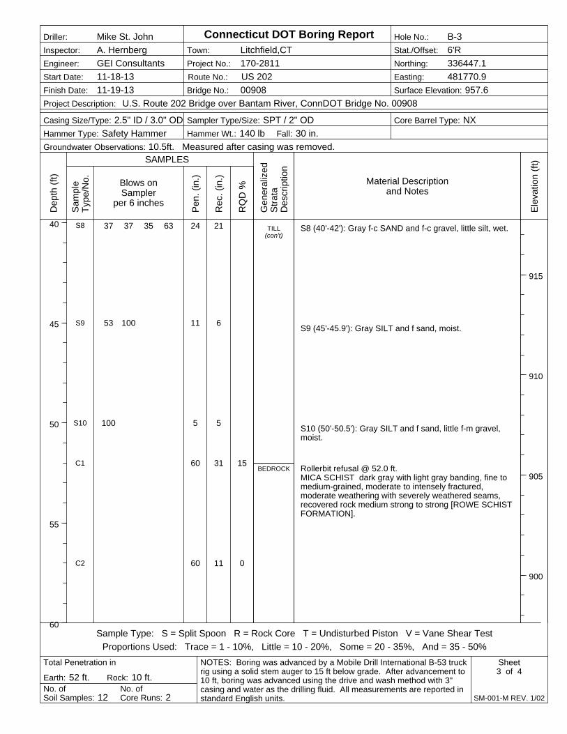
37 37 35 63
53 100
100
24
11
5
60
60
21
6
5
31
11
15
0
TILL(con't)
BEDROCK
S8
S9
S10
C1
C2
S8 (40'-42'): Gray f-c SAND and f-c gravel, little silt, wet.
S9 (45'-45.9'): Gray SILT and f sand, moist.
S10 (50'-50.5'): Gray SILT and f sand, little f-m gravel,moist.
Rollerbit refusal @ 52.0 ft.MICA SCHIST dark gray with light gray banding, fine tomedium-grained, moderate to intensely fractured,moderate weathering with severely weathered seams,recovered rock medium strong to strong [ROWE SCHISTFORMATION].
Blows onSampler
per 6 inchesP
en.
(in.)
Rec
. (in
.)
Dep
th (
ft)
40
45
50
55
60
Project No.: 170-2811
Ele
vatio
n (f
t)
915
910
905
900
Hammer Wt.: 140 lb
Town: Litchfield,CT
No. ofCore Runs: 2
Inspector: A. Hernberg
Earth: 52 ft. Rock: 10 ft.
Bridge No.: 00908
Sampler Type/Size: SPT / 2" ODCasing Size/Type: 2.5" ID / 3.0" OD
RQ
D %
Engineer: GEI Consultants
Core Barrel Type: NX
No. ofSoil Samples: 12
Total Penetration in
Fall: 30 in.
Project Description: U.S. Route 202 Bridge over Bantam River, ConnDOT Bridge No. 00908
Gen
eral
ized
Str
ata
Des
crip
tion
Route No.: US 202
NOTES: Boring was advanced by a Mobile Drill International B-53 truckrig using a solid stem auger to 15 ft below grade. After advancement to10 ft, boring was advanced using the drive and wash method with 3"casing and water as the drilling fluid. All measurements are reported instandard English units.
Sample Type: S = Split Spoon R = Rock Core T = Undisturbed Piston V = Vane Shear Test
Proportions Used: Trace = 1 - 10%, Little = 10 - 20%, Some = 20 - 35%, And = 35 - 50%
Hole No.: B-3
Sheet3 of 4
SAMPLES
Connecticut DOT Boring Report
SM-001-M REV. 1/02
Stat./Offset: 6'R
Groundwater Observations: 10.5ft. Measured after casing was removed.
Northing: 336447.1
Easting: 481770.9
Surface Elevation: 957.6
Driller: Mike St. John
Start Date: 11-18-13
Finish Date: 11-19-13
Sam
ple
Typ
e/N
o. Material Descriptionand Notes
Hammer Type: Safety Hammer
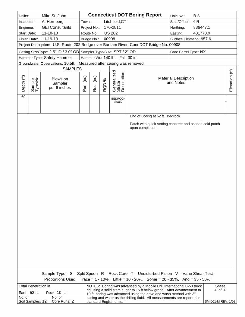
BEDROCK(con't)
End of Boring at 62 ft. Bedrock.
Patch with quick-setting concrete and asphalt cold patchupon completion.
Blows onSampler
per 6 inchesP
en.
(in.)
Rec
. (in
.)
Dep
th (
ft)
60
Project No.: 170-2811
Ele
vatio
n (f
t)
Hammer Wt.: 140 lb
Town: Litchfield,CT
No. ofCore Runs: 2
Inspector: A. Hernberg
Earth: 52 ft. Rock: 10 ft.
Bridge No.: 00908
Sampler Type/Size: SPT / 2" ODCasing Size/Type: 2.5" ID / 3.0" OD
RQ
D %
Engineer: GEI Consultants
Core Barrel Type: NX
No. ofSoil Samples: 12
Total Penetration in
Fall: 30 in.
Project Description: U.S. Route 202 Bridge over Bantam River, ConnDOT Bridge No. 00908
Gen
eral
ized
Str
ata
Des
crip
tion
Route No.: US 202
NOTES: Boring was advanced by a Mobile Drill International B-53 truckrig using a solid stem auger to 15 ft below grade. After advancement to10 ft, boring was advanced using the drive and wash method with 3"casing and water as the drilling fluid. All measurements are reported instandard English units.
Sample Type: S = Split Spoon R = Rock Core T = Undisturbed Piston V = Vane Shear Test
Proportions Used: Trace = 1 - 10%, Little = 10 - 20%, Some = 20 - 35%, And = 35 - 50%
Hole No.: B-3
Sheet4 of 4
SAMPLES
Connecticut DOT Boring Report
SM-001-M REV. 1/02
Stat./Offset: 6'R
Groundwater Observations: 10.5ft. Measured after casing was removed.
Northing: 336447.1
Easting: 481770.9
Surface Elevation: 957.6
Driller: Mike St. John
Start Date: 11-18-13
Finish Date: 11-19-13
Sam
ple
Typ
e/N
o. Material Descriptionand Notes
Hammer Type: Safety Hammer
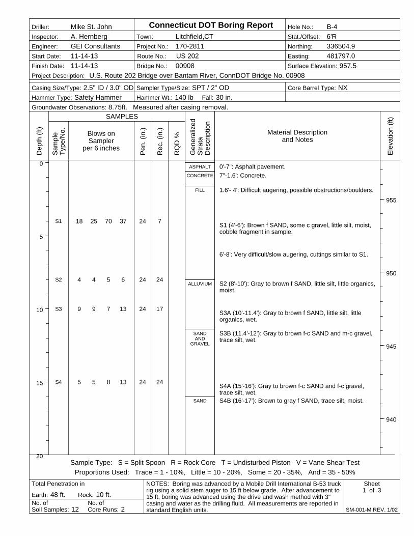
18 25 70 37
4 4 5 6
9 9 7 13
5 5 8 13
24
24
24
24
7
24
17
24
ASPHALT
CONCRETE
FILL
ALLUVIUM
SANDAND
GRAVEL
SAND
S1
S2
S3
S4
0'-7": Asphalt pavement.
7"-1.6': Concrete.
1.6'- 4': Difficult augering, possible obstructions/boulders.
S1 (4'-6'): Brown f SAND, some c gravel, little silt, moist,cobble fragment in sample.
6'-8': Very difficult/slow augering, cuttings similar to S1.
S2 (8'-10'): Gray to brown f SAND, little silt, little organics,moist.
S3A (10'-11.4'): Gray to brown f SAND, little silt, littleorganics, wet.
S3B (11.4'-12'): Gray to brown f-c SAND and m-c gravel,trace silt, wet.
S4A (15'-16'): Gray to brown f-c SAND and f-c gravel,trace silt, wet.S4B (16'-17'): Brown to gray f SAND, trace silt, moist.
Blows onSampler
per 6 inchesP
en.
(in.)
Rec
. (in
.)
Dep
th (
ft)
0
5
10
15
20
Project No.: 170-2811
Ele
vatio
n (f
t)
955
950
945
940
Hammer Wt.: 140 lb
Town: Litchfield,CT
No. ofCore Runs: 2
Inspector: A. Hernberg
Earth: 48 ft. Rock: 10 ft.
Bridge No.: 00908
Sampler Type/Size: SPT / 2" ODCasing Size/Type: 2.5" ID / 3.0" OD
RQ
D %
Engineer: GEI Consultants
Core Barrel Type: NX
No. ofSoil Samples: 12
Total Penetration in
Fall: 30 in.
Project Description: U.S. Route 202 Bridge over Bantam River, ConnDOT Bridge No. 00908
Gen
eral
ized
Str
ata
Des
crip
tion
Route No.: US 202
NOTES: Boring was advanced by a Mobile Drill International B-53 truckrig using a solid stem auger to 15 ft below grade. After advancement to15 ft, boring was advanced using the drive and wash method with 3"casing and water as the drilling fluid. All measurements are reported instandard English units.
Sample Type: S = Split Spoon R = Rock Core T = Undisturbed Piston V = Vane Shear Test
Proportions Used: Trace = 1 - 10%, Little = 10 - 20%, Some = 20 - 35%, And = 35 - 50%
Hole No.: B-4
Sheet1 of 3
SAMPLES
Connecticut DOT Boring Report
SM-001-M REV. 1/02
Stat./Offset: 6'R
Groundwater Observations: 8.75ft. Measured after casing removal.
Northing: 336504.9
Easting: 481797.0
Surface Elevation: 957.5
Driller: Mike St. John
Start Date: 11-14-13
Finish Date: 11-14-13
Sam
ple
Typ
e/N
o. Material Descriptionand Notes
Hammer Type: Safety Hammer
4 4 7 6
1 2 2 3
2 8 22 21
6 6 6 6
24
24
24
24
13
24
9
8
SAND(con't)
CLAYEYSILT
SAND
SANDAND
GRAVEL
S5
S6
S7
S8
S5 (20'-22'): Brown to gray f SAND, little silt, wet.
S6 (25'-27'): Gray SILT, little f sand, moist.
S7A (30'-31.8'): Gray f SAND, little silt, moist.
S7B (31.8'-32'): Gray c GRAVEL, little f sand, wet.
S8 (35'-37'): Gray to brown f-c SAND and f-c gravel, wet.
Blows onSampler
per 6 inchesP
en.
(in.)
Rec
. (in
.)
Dep
th (
ft)
20
25
30
35
40
Project No.: 170-2811
Ele
vatio
n (f
t)
935
930
925
920
Hammer Wt.: 140 lb
Town: Litchfield,CT
No. ofCore Runs: 2
Inspector: A. Hernberg
Earth: 48 ft. Rock: 10 ft.
Bridge No.: 00908
Sampler Type/Size: SPT / 2" ODCasing Size/Type: 2.5" ID / 3.0" OD
RQ
D %
Engineer: GEI Consultants
Core Barrel Type: NX
No. ofSoil Samples: 12
Total Penetration in
Fall: 30 in.
Project Description: U.S. Route 202 Bridge over Bantam River, ConnDOT Bridge No. 00908
Gen
eral
ized
Str
ata
Des
crip
tion
Route No.: US 202
NOTES: Boring was advanced by a Mobile Drill International B-53 truckrig using a solid stem auger to 15 ft below grade. After advancement to15 ft, boring was advanced using the drive and wash method with 3"casing and water as the drilling fluid. All measurements are reported instandard English units.
Sample Type: S = Split Spoon R = Rock Core T = Undisturbed Piston V = Vane Shear Test
Proportions Used: Trace = 1 - 10%, Little = 10 - 20%, Some = 20 - 35%, And = 35 - 50%
Hole No.: B-4
Sheet2 of 3
SAMPLES
Connecticut DOT Boring Report
SM-001-M REV. 1/02
Stat./Offset: 6'R
Groundwater Observations: 8.75ft. Measured after casing removal.
Northing: 336504.9
Easting: 481797.0
Surface Elevation: 957.5
Driller: Mike St. John
Start Date: 11-14-13
Finish Date: 11-14-13
Sam
ple
Typ
e/N
o. Material Descriptionand Notes
Hammer Type: Safety Hammer
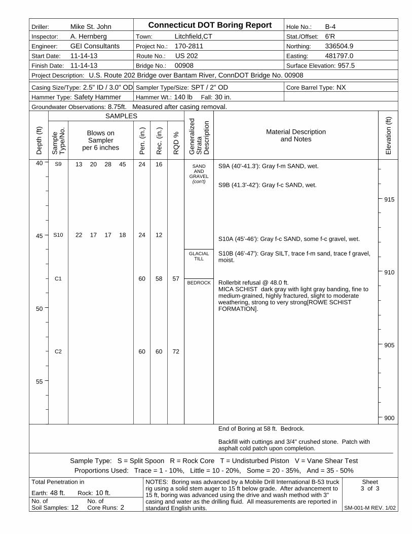
13 20 28 45
22 17 17 18
24
24
60
60
16
12
58
60
57
72
SANDAND
GRAVEL(con't)
GLACIALTILL
BEDROCK
S9
S10
C1
C2
S9A (40'-41.3'): Gray f-m SAND, wet.
S9B (41.3'-42'): Gray f-c SAND, wet.
S10A (45'-46'): Gray f-c SAND, some f-c gravel, wet.
S10B (46'-47'): Gray SILT, trace f-m sand, trace f gravel,moist.
Rollerbit refusal @ 48.0 ft.MICA SCHIST dark gray with light gray banding, fine tomedium-grained, highly fractured, slight to moderateweathering, strong to very strong[ROWE SCHISTFORMATION].
End of Boring at 58 ft. Bedrock.
Backfill with cuttings and 3/4" crushed stone. Patch withasphalt cold patch upon completion.
Blows onSampler
per 6 inchesP
en.
(in.)
Rec
. (in
.)
Dep
th (
ft)
40
45
50
55
Project No.: 170-2811
Ele
vatio
n (f
t)
915
910
905
900
Hammer Wt.: 140 lb
Town: Litchfield,CT
No. ofCore Runs: 2
Inspector: A. Hernberg
Earth: 48 ft. Rock: 10 ft.
Bridge No.: 00908
Sampler Type/Size: SPT / 2" ODCasing Size/Type: 2.5" ID / 3.0" OD
RQ
D %
Engineer: GEI Consultants
Core Barrel Type: NX
No. ofSoil Samples: 12
Total Penetration in
Fall: 30 in.
Project Description: U.S. Route 202 Bridge over Bantam River, ConnDOT Bridge No. 00908
Gen
eral
ized
Str
ata
Des
crip
tion
Route No.: US 202
NOTES: Boring was advanced by a Mobile Drill International B-53 truckrig using a solid stem auger to 15 ft below grade. After advancement to15 ft, boring was advanced using the drive and wash method with 3"casing and water as the drilling fluid. All measurements are reported instandard English units.
Sample Type: S = Split Spoon R = Rock Core T = Undisturbed Piston V = Vane Shear Test
Proportions Used: Trace = 1 - 10%, Little = 10 - 20%, Some = 20 - 35%, And = 35 - 50%
Hole No.: B-4
Sheet3 of 3
SAMPLES
Connecticut DOT Boring Report
SM-001-M REV. 1/02
Stat./Offset: 6'R
Groundwater Observations: 8.75ft. Measured after casing removal.
Northing: 336504.9
Easting: 481797.0
Surface Elevation: 957.5
Driller: Mike St. John
Start Date: 11-14-13
Finish Date: 11-14-13
Sam
ple
Typ
e/N
o. Material Descriptionand Notes
Hammer Type: Safety Hammer
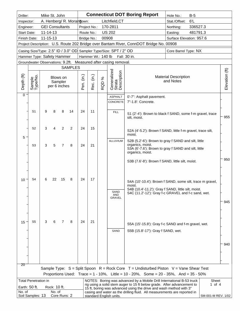
9 8 8 14
3 4 2 2
3 5 7 8
6 22 15 8
3 6 7 8
24
24
24
24
24
11
15
21
17
21
ASPHALT
CONCRETE
FILL
ALLUVIUM
SANDAND
GRAVEL
SAND
S1
S2
S3
S4
S5
0'-7": Asphalt pavement.
7"-1.8': Concrete.
S1 (2'-4'): Brown to black f SAND, some f-m gravel, tracesilt, moist.
S2A (4'-5.2'): Brown f SAND, little f-m gravel, trace silt,moist.
S2B (5.2'-6'): Brown to gray f SAND and silt, littleorganics, moist.S3A (6'-7.6'): Brown to gray f SAND and silt, littleorganics, moist.
S3B (7.6'-8'): Brown f SAND, little silt, moist.
S4A (10'-10.4'): Brown f SAND, some silt, trace m gravel,moist.S4B (10.4'-11.2'): Gray f SAND, little silt, moist.S4C (11.2'-12'): Gray f-c GRAVEL and f-c sand, wet.
S5A (15'-15.8'): Gray f-c SAND and f-m gravel, wet.
S5B (15.8'-17'): Gray f SAND, wet.
Blows onSampler
per 6 inchesP
en.
(in.)
Rec
. (in
.)
Dep
th (
ft)
0
5
10
15
20
Project No.: 170-2811
Ele
vatio
n (f
t)
955
950
945
940
Hammer Wt.: 140 lb
Town: Litchfield,CT
No. ofCore Runs: 2
Inspector: A. Henberg/ R. Morang
Earth: 50 ft. Rock: 10 ft.
Bridge No.: 00908
Sampler Type/Size: SPT / 2" ODCasing Size/Type: 2.5" ID / 3.0" OD
RQ
D %
Engineer: GEI Consultants
Core Barrel Type: NX
No. ofSoil Samples: 13
Total Penetration in
Fall: 30 in.
Project Description: U.S. Route 202 Bridge over Bantam River, ConnDOT Bridge No. 00908
Gen
eral
ized
Str
ata
Des
crip
tion
Route No.: US 202
NOTES: Boring was advanced by a Mobile Drill International B-53 truckrig using a solid stem auger to 15 ft below grade. After advancement to15 ft, boring was advanced using the drive and wash method with 3"casing and water as the drilling fluid. All measurements are reported instandard English units.
Sample Type: S = Split Spoon R = Rock Core T = Undisturbed Piston V = Vane Shear Test
Proportions Used: Trace = 1 - 10%, Little = 10 - 20%, Some = 20 - 35%, And = 35 - 50%
Hole No.: B-5
Sheet1 of 4
SAMPLES
Connecticut DOT Boring Report
SM-001-M REV. 1/02
Stat./Offset: 6'L
Groundwater Observations: 9.2ft. Measured after casing removal.
Northing: 336527.3
Easting: 481791.3
Surface Elevation: 957.6
Driller: Mike St. John
Start Date: 11-14-13
Finish Date: 11-15-13
Sam
ple
Typ
e/N
o. Material Descriptionand Notes
Hammer Type: Safety Hammer
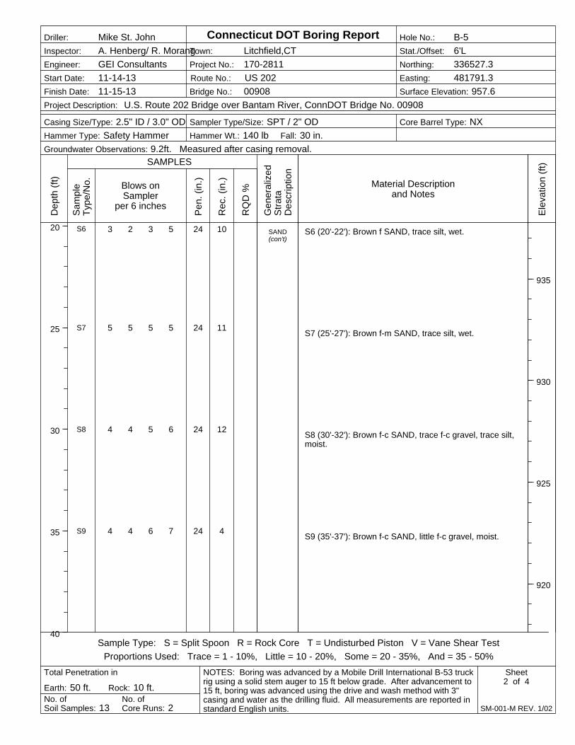
3 2 3 5
5 5 5 5
4 4 5 6
4 4 6 7
24
24
24
24
10
11
12
4
SAND(con't)
S6
S7
S8
S9
S6 (20'-22'): Brown f SAND, trace silt, wet.
S7 (25'-27'): Brown f-m SAND, trace silt, wet.
S8 (30'-32'): Brown f-c SAND, trace f-c gravel, trace silt,moist.
S9 (35'-37'): Brown f-c SAND, little f-c gravel, moist.
Blows onSampler
per 6 inchesP
en.
(in.)
Rec
. (in
.)
Dep
th (
ft)
20
25
30
35
40
Project No.: 170-2811
Ele
vatio
n (f
t)
935
930
925
920
Hammer Wt.: 140 lb
Town: Litchfield,CT
No. ofCore Runs: 2
Inspector: A. Henberg/ R. Morang
Earth: 50 ft. Rock: 10 ft.
Bridge No.: 00908
Sampler Type/Size: SPT / 2" ODCasing Size/Type: 2.5" ID / 3.0" OD
RQ
D %
Engineer: GEI Consultants
Core Barrel Type: NX
No. ofSoil Samples: 13
Total Penetration in
Fall: 30 in.
Project Description: U.S. Route 202 Bridge over Bantam River, ConnDOT Bridge No. 00908
Gen
eral
ized
Str
ata
Des
crip
tion
Route No.: US 202
NOTES: Boring was advanced by a Mobile Drill International B-53 truckrig using a solid stem auger to 15 ft below grade. After advancement to15 ft, boring was advanced using the drive and wash method with 3"casing and water as the drilling fluid. All measurements are reported instandard English units.
Sample Type: S = Split Spoon R = Rock Core T = Undisturbed Piston V = Vane Shear Test
Proportions Used: Trace = 1 - 10%, Little = 10 - 20%, Some = 20 - 35%, And = 35 - 50%
Hole No.: B-5
Sheet2 of 4
SAMPLES
Connecticut DOT Boring Report
SM-001-M REV. 1/02
Stat./Offset: 6'L
Groundwater Observations: 9.2ft. Measured after casing removal.
Northing: 336527.3
Easting: 481791.3
Surface Elevation: 957.6
Driller: Mike St. John
Start Date: 11-14-13
Finish Date: 11-15-13
Sam
ple
Typ
e/N
o. Material Descriptionand Notes
Hammer Type: Safety Hammer
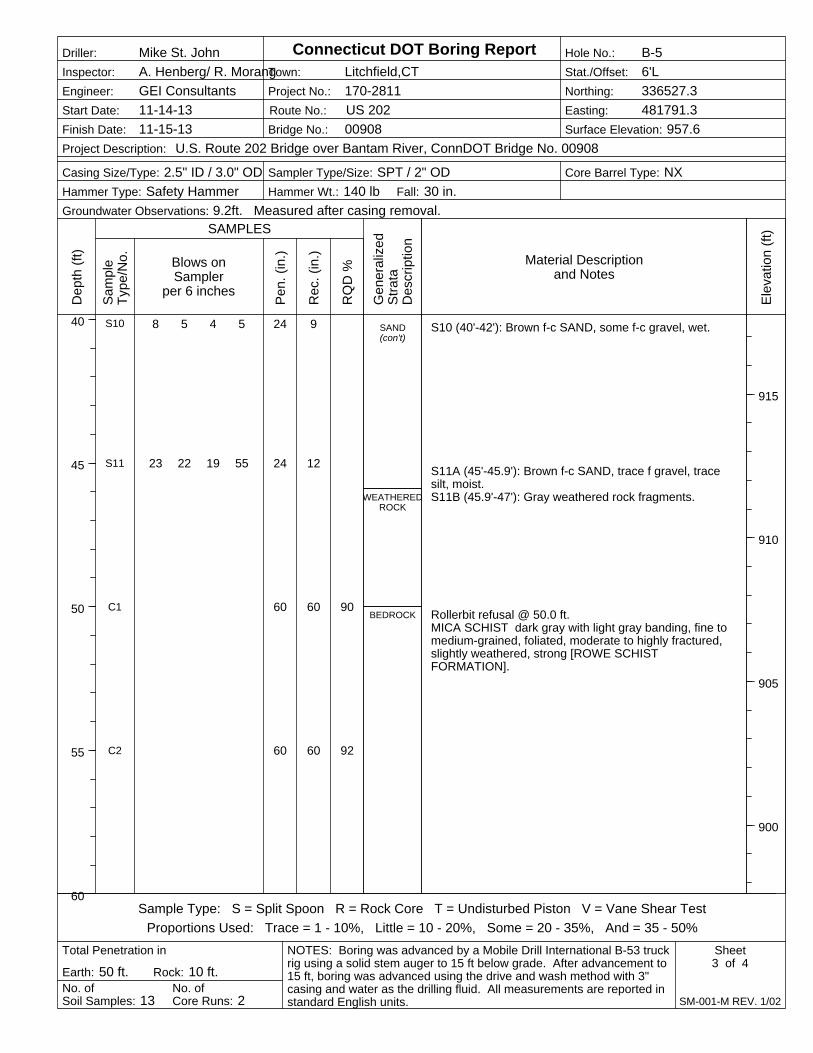
8 5 4 5
23 22 19 55
24
24
60
60
9
12
60
60
90
92
SAND(con't)
WEATHEREDROCK
BEDROCK
S10
S11
C1
C2
S10 (40'-42'): Brown f-c SAND, some f-c gravel, wet.
S11A (45'-45.9'): Brown f-c SAND, trace f gravel, tracesilt, moist.S11B (45.9'-47'): Gray weathered rock fragments.
Rollerbit refusal @ 50.0 ft.MICA SCHIST dark gray with light gray banding, fine tomedium-grained, foliated, moderate to highly fractured,slightly weathered, strong [ROWE SCHISTFORMATION].
Blows onSampler
per 6 inchesP
en.
(in.)
Rec
. (in
.)
Dep
th (
ft)
40
45
50
55
60
Project No.: 170-2811
Ele
vatio
n (f
t)
915
910
905
900
Hammer Wt.: 140 lb
Town: Litchfield,CT
No. ofCore Runs: 2
Inspector: A. Henberg/ R. Morang
Earth: 50 ft. Rock: 10 ft.
Bridge No.: 00908
Sampler Type/Size: SPT / 2" ODCasing Size/Type: 2.5" ID / 3.0" OD
RQ
D %
Engineer: GEI Consultants
Core Barrel Type: NX
No. ofSoil Samples: 13
Total Penetration in
Fall: 30 in.
Project Description: U.S. Route 202 Bridge over Bantam River, ConnDOT Bridge No. 00908
Gen
eral
ized
Str
ata
Des
crip
tion
Route No.: US 202
NOTES: Boring was advanced by a Mobile Drill International B-53 truckrig using a solid stem auger to 15 ft below grade. After advancement to15 ft, boring was advanced using the drive and wash method with 3"casing and water as the drilling fluid. All measurements are reported instandard English units.
Sample Type: S = Split Spoon R = Rock Core T = Undisturbed Piston V = Vane Shear Test
Proportions Used: Trace = 1 - 10%, Little = 10 - 20%, Some = 20 - 35%, And = 35 - 50%
Hole No.: B-5
Sheet3 of 4
SAMPLES
Connecticut DOT Boring Report
SM-001-M REV. 1/02
Stat./Offset: 6'L
Groundwater Observations: 9.2ft. Measured after casing removal.
Northing: 336527.3
Easting: 481791.3
Surface Elevation: 957.6
Driller: Mike St. John
Start Date: 11-14-13
Finish Date: 11-15-13
Sam
ple
Typ
e/N
o. Material Descriptionand Notes
Hammer Type: Safety Hammer
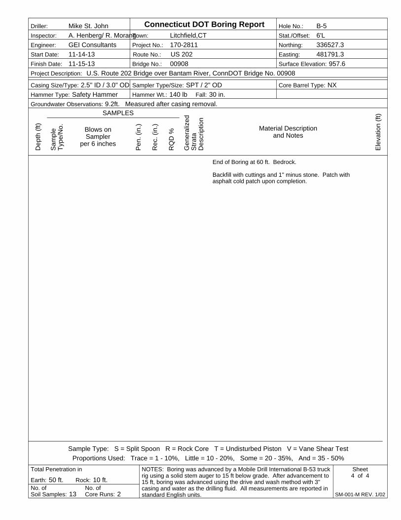
End of Boring at 60 ft. Bedrock.
Backfill with cuttings and 1" minus stone. Patch withasphalt cold patch upon completion.
Blows onSampler
per 6 inchesP
en.
(in.)
Rec
. (in
.)
Dep
th (
ft)
Project No.: 170-2811
Ele
vatio
n (f
t)
Hammer Wt.: 140 lb
Town: Litchfield,CT
No. ofCore Runs: 2
Inspector: A. Henberg/ R. Morang
Earth: 50 ft. Rock: 10 ft.
Bridge No.: 00908
Sampler Type/Size: SPT / 2" ODCasing Size/Type: 2.5" ID / 3.0" OD
RQ
D %
Engineer: GEI Consultants
Core Barrel Type: NX
No. ofSoil Samples: 13
Total Penetration in
Fall: 30 in.
Project Description: U.S. Route 202 Bridge over Bantam River, ConnDOT Bridge No. 00908
Gen
eral
ized
Str
ata
Des
crip
tion
Route No.: US 202
NOTES: Boring was advanced by a Mobile Drill International B-53 truckrig using a solid stem auger to 15 ft below grade. After advancement to15 ft, boring was advanced using the drive and wash method with 3"casing and water as the drilling fluid. All measurements are reported instandard English units.
Sample Type: S = Split Spoon R = Rock Core T = Undisturbed Piston V = Vane Shear Test
Proportions Used: Trace = 1 - 10%, Little = 10 - 20%, Some = 20 - 35%, And = 35 - 50%
Hole No.: B-5
Sheet4 of 4
SAMPLES
Connecticut DOT Boring Report
SM-001-M REV. 1/02
Stat./Offset: 6'L
Groundwater Observations: 9.2ft. Measured after casing removal.
Northing: 336527.3
Easting: 481791.3
Surface Elevation: 957.6
Driller: Mike St. John
Start Date: 11-14-13
Finish Date: 11-15-13
Sam
ple
Typ
e/N
o. Material Descriptionand Notes
Hammer Type: Safety Hammer

CT DOT Bridge No. 00908 Route 202 Over Bantam River Litchfield, Connecticut September 12, 2017
GEI Consultants, Inc.
Appendix C
Laboratory Test Results
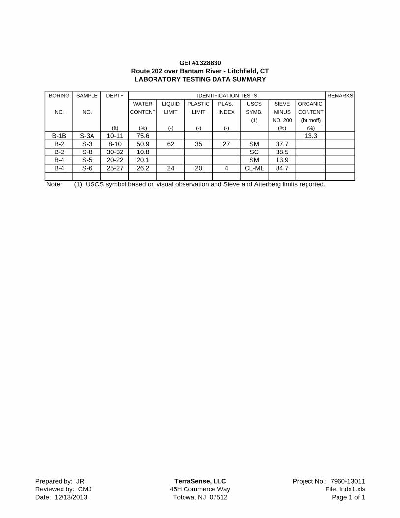
GEI #1328830Route 202 over Bantam River - Litchfield, CTLABORATORY TESTING DATA SUMMARY
BORING SAMPLE DEPTH IDENTIFICATION TESTS REMARKS
WATER LIQUID PLASTIC PLAS. USCS SIEVE ORGANIC
NO. NO. CONTENT LIMIT LIMIT INDEX SYMB. MINUS CONTENT
(1) NO. 200 (burnoff)
(ft) (%) (-) (-) (-) (%) (%)
B-1B S-3A 10-11 75.6 13.3B-2 S-3 8-10 50.9 62 35 27 SM 37.7B-2 S-8 30-32 10.8 SC 38.5B-4 S-5 20-22 20.1 SM 13.9B-4 S-6 25-27 26.2 24 20 4 CL-ML 84.7
Note: (1) USCS symbol based on visual observation and Sieve and Atterberg limits reported.
Prepared by: JRReviewed by: CMJDate: 12/13/2013
TerraSense, LLC45H Commerce WayTotowa, NJ 07512
Project No.: 7960-13011File: Indx1.xls
Page 1 of 1

COBBLES GRAVEL SAND SILT OR CLAY Symbol COARSE FINE COARSE MEDIUM FINE Boring B-2 B-2
U.S. Standard Sieve Size Sample S-3 S-8
Depth 8-10 30-32
% +3" 0.0 0.0
% Gravel 0.0 12.1
% SAND 62.3 49.4
%C SAND 0.4 6.7
%M SAND 6.2 12.3
%F SAND 55.6 30.4
% FINES 37.7 38.5
% -2
D100 (mm) 4.75 19.00
D60 (mm) 0.15 0.23
D30 (mm)
D10 (mm)
Cc
Cu
Particle Size PERCENT FINER
(Sieve #) 4"
3"
1 1/2"
3/4" 100.0
3/8" 94.1
4 100.0 87.9
10 99.6 81.2
20 98.0 75.7
40 93.4 68.9
60 79.8 61.6
SYMBOL w (%) LL PL PI USCS DESCRIPTION AND REMARKS Date Tested 100 60.3 51.8 50.9 62 35 27 SM 12/9/2013 200 37.7 38.5
10.8 SC 12/9/2013
7960-13011 1328830 PARTICLE SIZE DISTRIBUTION
TerraSense, LLC GEI
Route 202 over Bantam River - Litchfield, CT
Black, Silty sand
Gray, Clayey sand
0
10
20
30
40
50
60
70
80
90
100
0.0010.010.1110100
PE
RC
EN
T P
AS
SIN
G B
Y W
EIG
HT
PARTICLE SIZE -mm
#4 #60
#40
#20
#10
3/8"
3/4"
3" 1 1/
2"
4"
#100
#200
Analysis File: 3SV-MasterRev3 siev1a.xls 12/13/2013
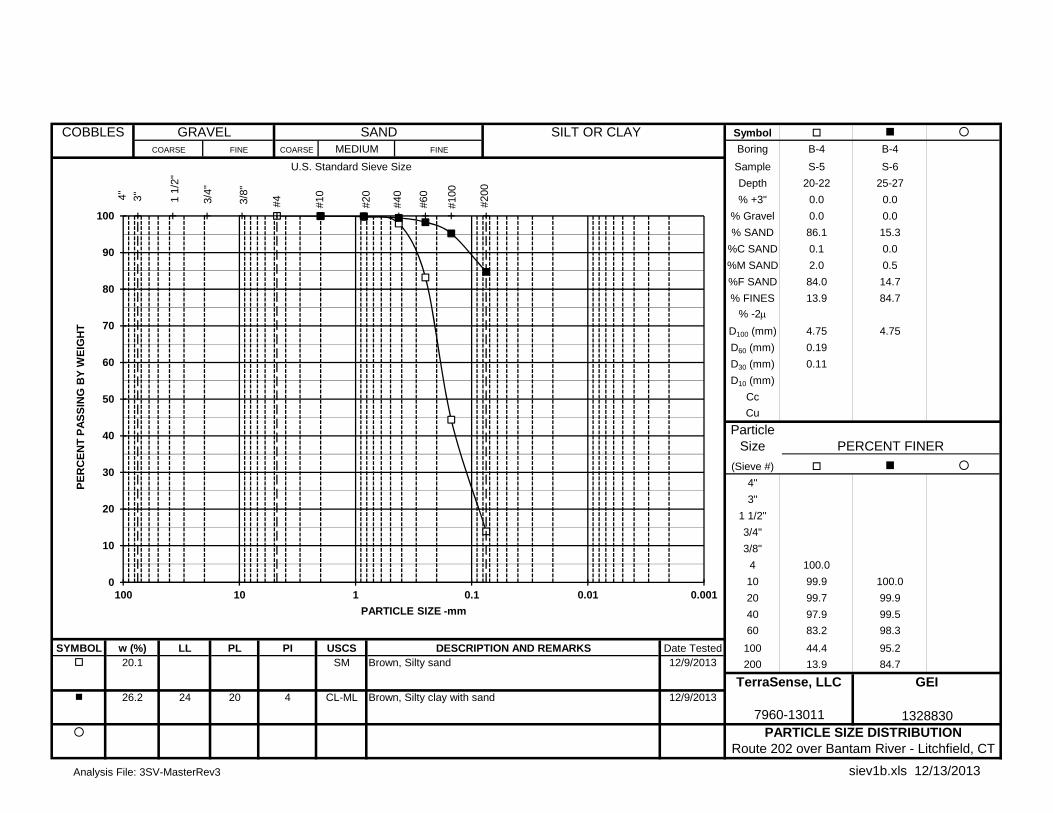
COBBLES GRAVEL SAND SILT OR CLAY Symbol COARSE FINE COARSE MEDIUM FINE Boring B-4 B-4
U.S. Standard Sieve Size Sample S-5 S-6
Depth 20-22 25-27
% +3" 0.0 0.0
% Gravel 0.0 0.0
% SAND 86.1 15.3
%C SAND 0.1 0.0
%M SAND 2.0 0.5
%F SAND 84.0 14.7
% FINES 13.9 84.7
% -2
D100 (mm) 4.75 4.75
D60 (mm) 0.19
D30 (mm) 0.11
D10 (mm)
Cc
Cu
Particle Size PERCENT FINER
(Sieve #) 4"
3"
1 1/2"
3/4"
3/8"
4 100.0
10 99.9 100.0
20 99.7 99.9
40 97.9 99.5
60 83.2 98.3
SYMBOL w (%) LL PL PI USCS DESCRIPTION AND REMARKS Date Tested 100 44.4 95.2 20.1 SM 12/9/2013 200 13.9 84.7
26.2 24 20 4 CL-ML 12/9/2013
7960-13011 1328830 PARTICLE SIZE DISTRIBUTION
TerraSense, LLC GEI
Route 202 over Bantam River - Litchfield, CT
Brown, Silty sand
Brown, Silty clay with sand
0
10
20
30
40
50
60
70
80
90
100
0.0010.010.1110100
PE
RC
EN
T P
AS
SIN
G B
Y W
EIG
HT
PARTICLE SIZE -mm
#4 #60
#40
#20
#10
3/8"
3/4"
3" 1 1/
2"
4"
#100
#200
Analysis File: 3SV-MasterRev3 siev1b.xls 12/13/2013
CT DOT Bridge No. 00908 Route 202 Over Bantam River Litchfield, Connecticut September 12, 2017
GEI Consultants, Inc.
Appendix D
Geotechnical Calculations

Table D1. GROUP Analyses - Unfactored LoadsRt 202 over Bantam River
Litchfield, CT
GEI Project # 1328830
CENTER PIER
LOADLOAD
ABBREVIATION
FX(K)
FY(K)
MZ
(K‐FT)
FZ(K)
MY
(K‐FT)
MX
(K‐FT)
DEAD LOAD DC 790
WEARING SURFACE DW 81.24
ICE IC 5 21 56.5 25 282.5
VERTICAL EARTH EV 80
LIVE LOAD LL 279.2
BRAKING BR 61.2 1408
EARTHQUAKE I EQ 40.4 626.2 134.8 2089.4
EARTHQUAKE II EQ 134.8 2089.4 40.4 626.2
STREAM LOAD WA 35.4 548.7
WIND ON SUPERSTRUCTURE WS 1.3 20 11.3 175
WIND ON LIVE LOAD WL 1.73 40 4.65 107
BUOYANCY BOUYANCY 168.3
ABUTMENT NO. 2
LOADFX(K)
FY(K)
MZ
(K‐FT)
FZ(K)
MY
(K‐FT)
MX
(K‐FT)
DEAD LOAD 570.9 361.8
WEARING SURFACE 24.4 42.7
VERTICAL EARTH 156.7 ‐392.4
LIVE LOAD 233.1 407.9
BRAKING 27.7 506.1
EARTHQUAKE I 23.6 257.9 23.6 257.9
STREAM LOAD 12.7 138.8
WIND ON SUPERSTRUCTURE 5.7 62.3
WIND ON LIVE LOAD 1.73 31.6 2.3 42
TEMPERATURE 13.5 124.6
HORIZONTAL EARTH ‐74.4 260.4
General Notes:
1. Unfactored Loads provided by Parsons Transportation Group.
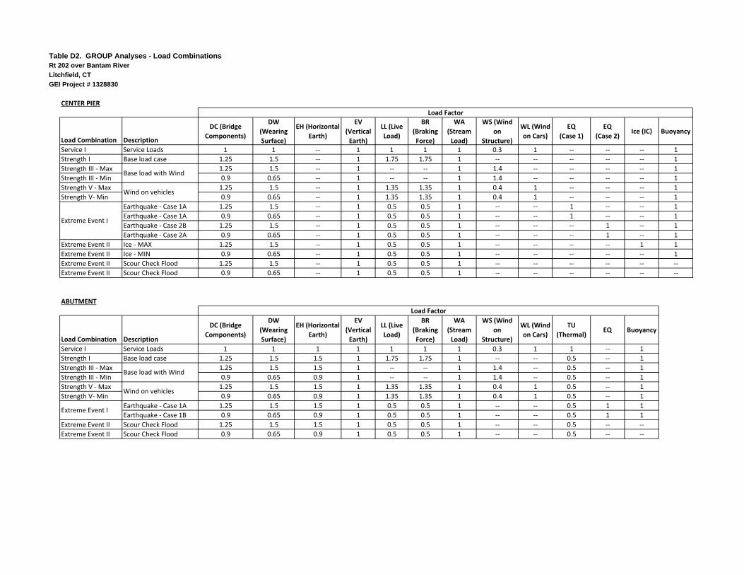
Table D2. GROUP Analyses - Load CombinationsRt 202 over Bantam River
Litchfield, CT
GEI Project # 1328830
Load Combination Description
DC (Bridge
Components)
DW
(Wearing
Surface)
EH (Horizontal
Earth)
EV
(Vertical
Earth)
LL (Live
Load)
BR
(Braking
Force)
WA
(Stream
Load)
WS (Wind
on
Structure)
WL (Wind
on Cars)
EQ
(Case 1)
EQ
(Case 2)Ice (IC) Buoyancy
Service I Service Loads 1 1 ‐‐ 1 1 1 1 0.3 1 ‐‐ ‐‐ ‐‐ 1
Strength I Base load case 1.25 1.5 ‐‐ 1 1.75 1.75 1 ‐‐ ‐‐ ‐‐ ‐‐ ‐‐ 1
Strength III ‐ Max 1.25 1.5 ‐‐ 1 ‐‐ ‐‐ 1 1.4 ‐‐ ‐‐ ‐‐ ‐‐ 1
Strength III ‐ Min 0.9 0.65 ‐‐ 1 ‐‐ ‐‐ 1 1.4 ‐‐ ‐‐ ‐‐ ‐‐ 1
Strength V ‐ Max 1.25 1.5 ‐‐ 1 1.35 1.35 1 0.4 1 ‐‐ ‐‐ ‐‐ 1
Strength V‐ Min 0.9 0.65 ‐‐ 1 1.35 1.35 1 0.4 1 ‐‐ ‐‐ ‐‐ 1
Earthquake ‐ Case 1A 1.25 1.5 ‐‐ 1 0.5 0.5 1 ‐‐ ‐‐ 1 ‐‐ ‐‐ 1
Earthquake ‐ Case 1A 0.9 0.65 ‐‐ 1 0.5 0.5 1 ‐‐ ‐‐ 1 ‐‐ ‐‐ 1
Earthquake ‐ Case 2B 1.25 1.5 ‐‐ 1 0.5 0.5 1 ‐‐ ‐‐ ‐‐ 1 ‐‐ 1
Earthquake ‐ Case 2A 0.9 0.65 ‐‐ 1 0.5 0.5 1 ‐‐ ‐‐ ‐‐ 1 ‐‐ 1
Extreme Event II Ice ‐ MAX 1.25 1.5 ‐‐ 1 0.5 0.5 1 ‐‐ ‐‐ ‐‐ ‐‐ 1 1
Extreme Event II Ice ‐ MIN 0.9 0.65 ‐‐ 1 0.5 0.5 1 ‐‐ ‐‐ ‐‐ ‐‐ ‐‐ 1
Extreme Event II Scour Check Flood 1.25 1.5 ‐‐ 1 0.5 0.5 1 ‐‐ ‐‐ ‐‐ ‐‐ ‐‐ ‐‐
Extreme Event II Scour Check Flood 0.9 0.65 ‐‐ 1 0.5 0.5 1 ‐‐ ‐‐ ‐‐ ‐‐ ‐‐ ‐‐
Load Combination Description
DC (Bridge
Components)
DW
(Wearing
Surface)
EH (Horizontal
Earth)
EV
(Vertical
Earth)
LL (Live
Load)
BR
(Braking
Force)
WA
(Stream
Load)
WS (Wind
on
Structure)
WL (Wind
on Cars)
TU
(Thermal)EQ Buoyancy
Service I Service Loads 1 1 1 1 1 1 1 0.3 1 1 ‐‐ 1
Strength I Base load case 1.25 1.5 1.5 1 1.75 1.75 1 ‐‐ ‐‐ 0.5 ‐‐ 1
Strength III ‐ Max 1.25 1.5 1.5 1 ‐‐ ‐‐ 1 1.4 ‐‐ 0.5 ‐‐ 1
Strength III ‐ Min 0.9 0.65 0.9 1 ‐‐ ‐‐ 1 1.4 ‐‐ 0.5 ‐‐ 1
Strength V ‐ Max 1.25 1.5 1.5 1 1.35 1.35 1 0.4 1 0.5 ‐‐ 1
Strength V‐ Min 0.9 0.65 0.9 1 1.35 1.35 1 0.4 1 0.5 ‐‐ 1
Earthquake ‐ Case 1A 1.25 1.5 1.5 1 0.5 0.5 1 ‐‐ ‐‐ 0.5 1 1
Earthquake ‐ Case 1B 0.9 0.65 0.9 1 0.5 0.5 1 ‐‐ ‐‐ 0.5 1 1
Extreme Event II Scour Check Flood 1.25 1.5 1.5 1 0.5 0.5 1 ‐‐ ‐‐ 0.5 ‐‐ ‐‐
Extreme Event II Scour Check Flood 0.9 0.65 0.9 1 0.5 0.5 1 ‐‐ ‐‐ 0.5 ‐‐ ‐‐
Wind on vehicles
Extreme Event I
Base load with Wind
Wind on vehicles
CENTER PIER
Extreme Event I
ABUTMENT
Base load with Wind
Load Factor
Load Factor
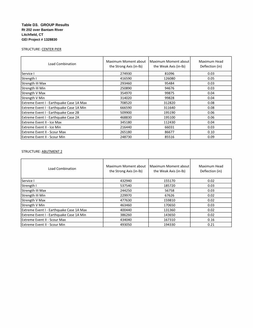
Table D3. GROUP ResultsRt 202 over Bantam River
Litchfield, CT
GEI Project # 1328830
STRUCTURE: CENTER PIER
Load CombinationMaximum Moment about
the Strong Axis (in‐lb)
Maximum Moment about
the Weak Axis (in‐lb)
Maximum Head
Deflection (in)
Service I 274930 81096 0.03
Strength I 416590 126080 0.05
Strength III Max 293460 95484 0.03
Strength III Min 250890 94676 0.03
Strength V Max 354970 99875 0.04
Strength V Min 314020 99828 0.04
Extreme Event I ‐ Earthquake Case 1A Max 708520 312820 0.08
Extreme Event I ‐ Earthquake Case 1A Min 666590 311640 0.08
Extreme Event I ‐ Earthquake Case 2B 509900 195190 0.06
Extreme Event I ‐ Earthquake Case 2A 468830 195100 0.06
Extreme Event II ‐ Ice Max 345180 112430 0.04
Extreme Event II ‐ Ice Min 216440 66031 0.03
Extreme Event II ‐ Scour Max 265180 86677 0.10
Extreme Event II ‐ Scour Min 248730 85516 0.09
STRUCTURE: ABUTMENT 2
Load CombinationMaximum Moment about
the Strong Axis (in‐lb)
Maximum Moment about
the Weak Axis (in‐lb)
Maximum Head
Deflection (in)
Service I 432940 155170 0.02
Strength I 537540 185720 0.03
Strength III Max 244250 56758 0.03
Strength III Min 229970 67626 0.02
Strength V Max 477630 159810 0.02
Strength V Min 463460 170650 0.03
Extreme Event I ‐ Earthquake Case 1A Max 400440 131360 0.02
Extreme Event I ‐ Earthquake Case 1A Min 386260 143650 0.02
Extreme Event II ‐ Scour Max 434040 167310 0.16
Extreme Event II ‐ Scour Min 493050 194330 0.21
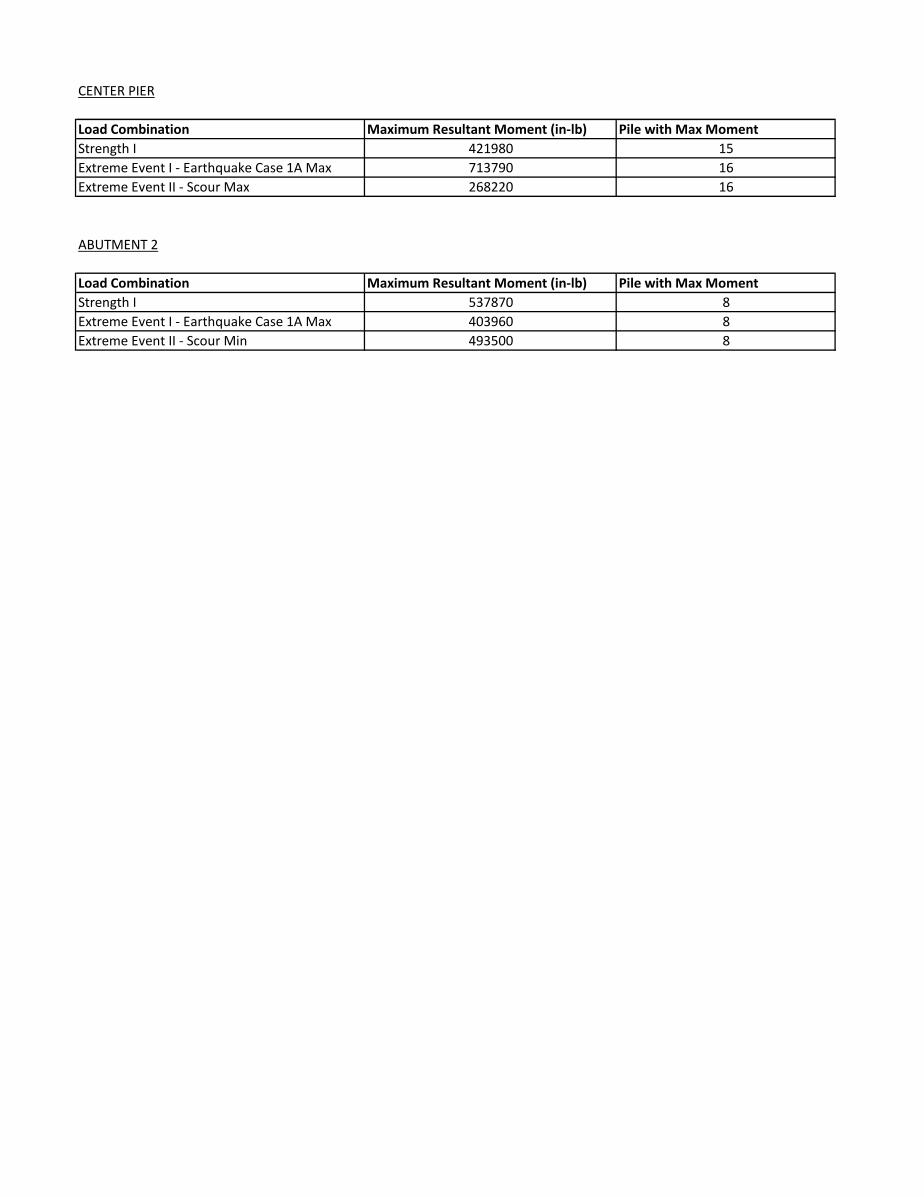
CENTER PIER
Load Combination Maximum Resultant Moment (in-lb) Pile with Max MomentStrength I 421980 15Extreme Event I - Earthquake Case 1A Max 713790 16Extreme Event II - Scour Max 268220 16
ABUTMENT 2
Load Combination Maximum Resultant Moment (in-lb) Pile with Max MomentStrength I 537870 8Extreme Event I - Earthquake Case 1A Max 403960 8Extreme Event II - Scour Min 493500 8
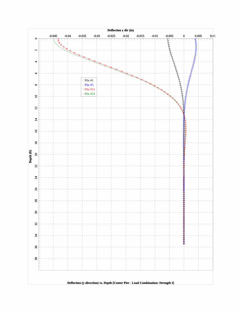
Deflection y dir (in)
Deflection (y-direction) vs. Depth [Center Pier - Load Combination: Strength I]
Dep
th (
ft)
-0.045 -0.04 -0.035 -0.03 -0.025 -0.02 -0.015 -0.01 -0.005 0 0.005 0.010
24
68
1012
1416
1820
2224
2628
3032
3436
38
Pile #1
Pile #5
Pile #11
Pile #15
Deflection y dir (in)
Deflection (y-direction) vs. Depth [Center Pier - Load Combination: Strength I]
Dep
th (
ft)
-0.045 -0.04 -0.035 -0.03 -0.025 -0.02 -0.015 -0.01 -0.005 0 0.005 0.00
24
68
1012
1416
1820
2224
2628
3032
3436
38
Pile #1
Pile #5
Pile #11
Pile #15
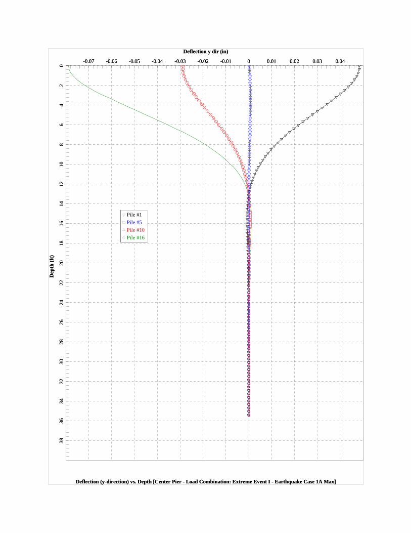
Deflection y dir (in)
Deflection (y-direction) vs. Depth [Center Pier - Load Combination: Extreme Event I - Earthquake Case 1A Max]
Dep
th (
ft)
-0.07 -0.06 -0.05 -0.04 -0.03 -0.02 -0.01 0 0.01 0.02 0.03 0.040
24
68
1012
1416
1820
2224
2628
3032
3436
38
Pile #1
Pile #5
Pile #10
Pile #16
Deflection y dir (in)
Deflection (y-direction) vs. Depth [Center Pier - Load Combination: Extreme Event I - Earthquake Case 1A Max]
Dep
th (
ft)
-0.07 -0.06 -0.05 -0.04 -0.03 -0.02 -0.01 0 0.01 0.02 0.03 0.040
24
68
1012
1416
1820
2224
2628
3032
3436
38
Pile #1
Pile #5
Pile #10
Pile #16
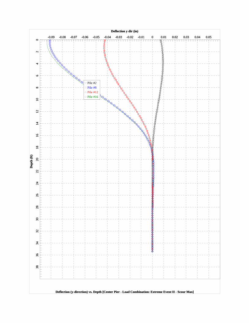
Deflection y dir (in)
Deflection (y-direction) vs. Depth [Center Pier - Load Combination: Extreme Event II - Scour Max]
Dep
th (
ft)
-0.09 -0.08 -0.07 -0.06 -0.05 -0.04 -0.03 -0.02 -0.01 0 0.01 0.02 0.03 0.04 0.050
24
68
1012
1416
1820
2224
2628
3032
3436
38
Pile #2
Pile #8
Pile #12
Pile #16
Deflection y dir (in)
Deflection (y-direction) vs. Depth [Center Pier - Load Combination: Extreme Event II - Scour Max]
Dep
th (
ft)
-0.09 -0.08 -0.07 -0.06 -0.05 -0.04 -0.03 -0.02 -0.01 0 0.01 0.02 0.03 0.04 0.050
24
68
1012
1416
1820
2224
2628
3032
3436
38
Pile #2
Pile #8
Pile #12
Pile #16
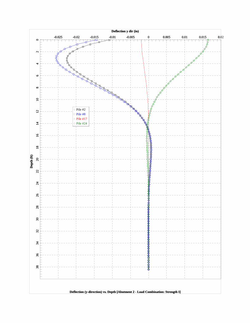
Deflection y dir (in)
Deflection (y-direction) vs. Depth [Abutment 2 - Load Combination: Strength I]
Dep
th (
ft)
-0.025 -0.02 -0.015 -0.01 -0.005 0 0.005 0.01 0.015 0.020
24
68
1012
1416
1820
2224
2628
3032
3436
38
Pile #2
Pile #8
Pile #17
Pile #24
Deflection y dir (in)
Deflection (y-direction) vs. Depth [Abutment 2 - Load Combination: Strength I]
Dep
th (
ft)
-0.025 -0.02 -0.015 -0.01 -0.005 0 0.005 0.01 0.015 0.00
24
68
1012
1416
1820
2224
2628
3032
3436
38
Pile #2
Pile #8
Pile #17
Pile #24
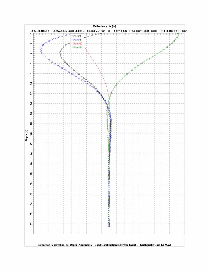
Deflection y dir (in)
Deflection (y-direction) vs. Depth [Abutment 2 - Load Combination: Extreme Event I - Earthquake Case 1A Max]
Dep
th (
ft)
-0.02 -0.018 -0.016 -0.014 -0.012 -0.01 -0.008 -0.006 -0.004 -0.002 0 0.002 0.004 0.006 0.008 0.01 0.012 0.014 0.016 0.018 0.020
24
68
1012
1416
1820
2224
2628
3032
3436
38
Pile #4
Pile #8
Pile #17
Pile #24
Deflection y dir (in)
Deflection (y-direction) vs. Depth [Abutment 2 - Load Combination: Extreme Event I - Earthquake Case 1A Max]
Dep
th (
ft)
-0.02 -0.018 -0.016 -0.014 -0.012 -0.01 -0.008 -0.006 -0.004 -0.002 0 0.002 0.004 0.006 0.008 0.01 0.012 0.014 0.016 0.018 0.00
24
68
1012
1416
1820
2224
2628
3032
3436
38
Pile #4
Pile #8
Pile #17
Pile #24

Deflection y dir (in)
Deflection (y-direction) vs. Depth [Abutment 2 - Load Combination: Extreme Event II - Scour Min]
Dep
th (
ft)
-0.2 -0.18 -0.16 -0.14 -0.12 -0.1 -0.08 -0.06 -0.04 -0.02 0 0.02 0.040
24
68
1012
1416
1820
2224
2628
3032
3436
38
Pile #4
Pile #8
Pile #17
Pile #24
Deflection y dir (in)
Deflection (y-direction) vs. Depth [Abutment 2 - Load Combination: Extreme Event II - Scour Min]
Dep
th (
ft)
-0.2 -0.18 -0.16 -0.14 -0.12 -0.1 -0.08 -0.06 -0.04 -0.02 0 0.02 0.00
24
68
1012
1416
1820
2224
2628
3032
3436
38
Pile #4
Pile #8
Pile #17
Pile #24
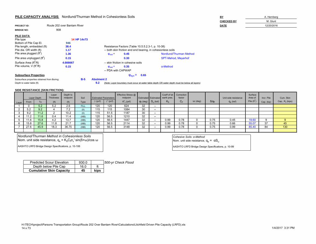
PILE CAPACITY ANALYSIS Nordlund/Thurman Method in Cohesionless Soils BY
CHECKED BY
PROJECT ID: Route 202 over Bantam River DATE
BRIDGE NO: 908
PILE DATA Pile type 14 HP 14x73
946Pile length, embedded (ft) 38.4 Resistance Factors (Table 10.5.5.2.3-1, p. 10-38)Pile dia. OR width (ft) 1.17 -- both skin friction and end bearing, in cohesionless soilsPile area plugged (ft2) 1.36 φstat = 0.45 Nordlund/Thurman MethodPile area unplugged (ft2) 0.15 0.30 SPT-Mehod, MeyerhofSurface Area (ft2/ft) 4.666667 -- skin friction in cohesive soilsPile volume, V (ft3/ft) 0.15 φstat = 0.35 α-Method
-- PDA with CAPWAP
Subsurface Properties φdyn = 0.65
Subsurface properties obtained from Boring: B-5 Abutment 2Depth to water table (ft) 9.2 (Note: Layer boundary must occur at water table depth OR water depth must be below all layers)
SIDE RESISTANCE (SKIN FRICTION):
Layer Thickness
Depth to midpoint Soil
Effective Stress @ midpoint Estimated Estimated
Coeff of lat earth pres.
Correction factor Unit side resistance
Surface Area of Incr. Pile Cum. Skin
From To (ft) (ft) Type (pcf) ' (pcf) σ'v (psf) φf (deg) Su (ksf) Kδ CF ω (deg) δ/φf qs (ksf) Pile (ft2) Cap. (kip) Cap., Rs (kips)
1 0 5.2 5.2 2.6 FILL 120 120 624 32 --2 5.2 9.2 4 7.2 (II) 115 115 1084 30 --3 9.2 11.2 2 10.2 (II) 115 51.5 1187 30 --4 11.2 11.6 0.4 11.4 (IIIB) 120 56.5 1210 32 --5 11.6 15.8 4.2 13.7 (IIIB) 120 56.5 1447 32 -- 0.99 0.78 0 0.75 0.45 19.60 9 96 15.8 27.6 11.8 21.7 (IIIB) 120 56.5 2114 32 -- 0.99 0.78 0 0.75 0.66 55.07 37 457 27.6 45.9 18.3 36.75 (IIIB) 120 56.5 3148 32 -- 0.99 0.78 0 0.75 0.99 85.40 84 130
930.0 500-yr Check Flood16.0 ft45 kips
Layer Depth Estimated Parameters
Predicted Scour ElevationDepth below Pile Cap
Cumulative Skin Capacity
A. Hernberg
M. Glunt
12/20/2016
Bottom of Pile Cap El.
Layer
Nordlund/Thurman Method in Cohesionless SoilsNom. unit side resistance, qs = KδCfσv' sin(δ+ω)/cos ω
AASHTO LRFD Bridge Design Specifications, p. 10-106
Cohesive Soils: α-MethodNom. unit side resistance, qs = αSu
AASHTO LRFD Bridge Design Specifications, p. 10-99
H:\TECH\project\Parsons Transportation Group\Route 202 Over Bantam River\Calculations\Litchfield Driven Pile Capacity (LRFD).xls14 x 73 1/4/2017 3:31 PM

Project: CTDOT Bridge 00908
GEI Project No.: 1328830
By:___L. McKiernan_____ _____
Checked:____M.Glunt______________
Date:_____6/4/16_____________
STATIC LATERAL EARTH PRESSURES: ABUTMENTS & WINGWALLS
REFERENCE: 2012 AASHTO LRFD BRIDGE DESIGN SPECIFICATIONS
2nd REFERENCE: 2003 CONNDOT BRIDGE DESIGN MANUAL
VALUE UNITS REFERENCE
Angle of Fill to the Horizontal (β) 0 ° Fig. 3.11.5.3‐1
Angle of the Back Face of the Wall to the Horizontal (θ) 90 ° Fig. 3.11.5.3‐1
Angle of Internal Friction for Backfill (φ'f) 35 ° Geo Report
FIND PASSIVE LATERAL EARTH PRESSURE COEFFICIENT:
Use Rankine Theory
Passive Lateral Earth Pressure Coefficient (kp) = tan2*(45 + /2) 3.69
FIND ACTIVE LATERAL EARTH PRESSURE COEFFICIENT :
Active Lateral Earth Pressure Coefficient (ka) = tan2*(45 ‐ /2) 0.27
H:\TECH\project\Parsons Transportation Group\Route 202 Over Bantam River\Calculations\Litchfield LEPs.xlsx
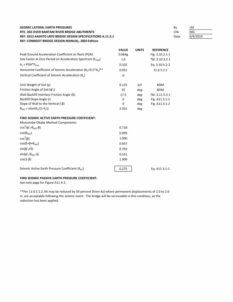
SEISMIC LATERAL EARTH PRESSURES By LM
RTE. 202 OVER BANTAM RIVER BRIDGE ABUTMENTS Chk MG
REF: 2012 AASHTO LRFD BRIDGE DESIGN SPECIFICATIONS A.11.3.1 Date 6/4/2014
REF: CONNDOT BRIDGE DESIGN MANUAL, 2003 Edition
VALUE UNITS REFERENCE
Peak Ground Acceleration Coefficient on Rock (PGA) 0.064g Fig. 3.10.2.1‐1
Site Factor at Zero Period on Acceleration Spectrum (FPGA) 1.6 Tbl. 3.10.3.2‐1
As = PGA*FPGA 0.102 Eq. 3.10.4.2‐2
Horizontal Coefficient of Seismic Acceleration (Kh=0.5*As)** 0.051 11.6.5.2.2
Vertical Coefficient of Seismic Acceleration (Kv) 0
Unit Weight of Soil (γ) 0.125 kcf BDM
Friction Angle of Soil (φ'f) 35 deg BDM
Wall‐Backfill Interface Friction Angle (δ) 17.5 deg Tbl. 3.11.5.3‐1
Backfill Slope Angle (i) 0 deg Fig. A11.3.1‐1
Slope of Wall to the Vertical (‐β) 0 deg Fig. A11.3.1‐2
θMO = atan(Kh/(1‐Kv)) 2.931 deg
FIND SEISMIC ACTIVE EARTH PRESSURE COEFFICIENT:
Mononobe‐Okabe Method Components:
cos2(φ'f‐θMO‐β) 0.718
cos(θMO) 0.999
cos2(β) 1.000
cos(δ+β+θMO) 0.937
sin(φ'f+δ) 0.793
sin(φ'f‐θMO‐i)) 0.531
cos(1‐β) 1.000
Seismic Active Earth Pressure Coefficient (KAE) 0.275 Eq. A11.3.1‐1
FIND SEISMIC PASSIVE EARTH PRESSURE COEFFICIENT:
See next page for Figure A11.4‐2.
**Per 11.6.5.2.2, Kh may be reduced by 50 percent (from As) where permanent displacements of 1.0 to 2.0
in. are acceptable following the seismic event. The bridge will be serviceable in this condition, so the
reduction has been applied.
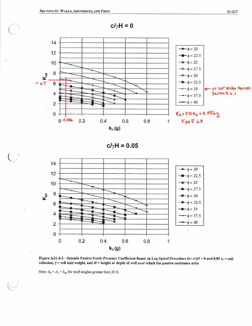
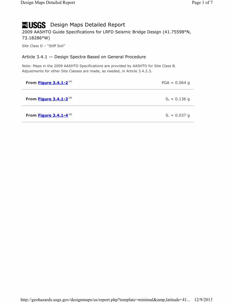
Design Maps Detailed Report
From Figure 3.4.1-2 [1]
From Figure 3.4.1-3 [2]
From Figure 3.4.1-4 [3]
2009 AASHTO Guide Specifications for LRFD Seismic Bridge Design (41.75598°N, 73.18286°W)
Site Class D – “Stiff Soil”
Article 3.4.1 — Design Spectra Based on General Procedure
Note: Maps in the 2009 AASHTO Specifications are provided by AASHTO for Site Class B.Adjustments for other Site Classes are made, as needed, in Article 3.4.2.3.
PGA = 0.064 g
SS = 0.136 g
S1 = 0.037 g
Page 1 of 7Design Maps Detailed Report
12/9/2013http://geohazards.usgs.gov/designmaps/us/report.php?template=minimal&latitude=41...

Article 3.4.2.1 — Site Class Definitions
The authority having jurisdiction (not the USGS), site-specific geotechnical data, and/or the default has classified the site as Site Class D, based on the site soil properties in accordance with Article 3.4.2.
Table 3.4.2.1–1 Site Class Definitions
SITE CLASS
SOIL PROFILE NAME
Soil shear wave velocity, vS, (ft/s)
Standard penetration resistance, N
Soil undrained shear strength, su, (psf)
A Hard rock vS > 5,000 N/A N/A
B Rock 2,500 < vS ≤ 5,000 N/A N/A
C Very dense soil and soft rock
1,200 < vS ≤ 2,500 N > 50 >2,000 psf
D Stiff soil profile 600 ≤ vS < 1,200 15 ≤ N ≤ 50 1,000 to 2,000 psf
E Stiff soil profile vS < 600 N < 15 <1,000 psf
E — Any profile with more than 10 ft of soil having the characteristics:
1. Plasticity index PI > 20,2. Moisture content w ≥ 40%, and3. Undrained shear strength su < 500 psf
F — Any profile containing soils having one or more of the followingcharacteristics:
1. Soils vulnerable to potential failure or collapse under seismic loading such as liquefiable soils, quick and highly sensitive clays, collapsible weakly cemented soils.
2. Peats and/or highly organic clays (H > 10 feet of peat and/or highly organic clay where H = thickness of soil)
3. Very high plasticity clays (H > 25 feet with plasticity index PI > 75)4. Very thick soft/medium stiff clays (H > 120 feet)
For SI: 1ft/s = 0.3048 m/s 1lb/ft² = 0.0479 kN/m²
Page 2 of 7Design Maps Detailed Report
12/9/2013http://geohazards.usgs.gov/designmaps/us/report.php?template=minimal&latitude=41...
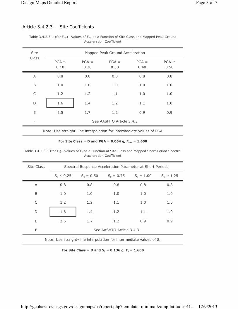
Article 3.4.2.3 — Site Coefficients
Table 3.4.2.3-1 (for Fpga)—Values of Fpga as a Function of Site Class and Mapped Peak Ground Acceleration Coefficient
Site Class
Mapped Peak Ground Acceleration
PGA ≤ 0.10
PGA = 0.20
PGA = 0.30
PGA = 0.40
PGA ≥ 0.50
A 0.8 0.8 0.8 0.8 0.8
B 1.0 1.0 1.0 1.0 1.0
C 1.2 1.2 1.1 1.0 1.0
D 1.6 1.4 1.2 1.1 1.0
E 2.5 1.7 1.2 0.9 0.9
F See AASHTO Article 3.4.3
Note: Use straight–line interpolation for intermediate values of PGA
For Site Class = D and PGA = 0.064 g, FPGA = 1.600
Table 3.4.2.3-1 (for Fa)—Values of Fa as a Function of Site Class and Mapped Short-Period Spectral Acceleration Coefficient
Site Class Spectral Response Acceleration Parameter at Short Periods
SS ≤ 0.25 SS = 0.50 SS = 0.75 SS = 1.00 SS ≥ 1.25
A 0.8 0.8 0.8 0.8 0.8
B 1.0 1.0 1.0 1.0 1.0
C 1.2 1.2 1.1 1.0 1.0
D 1.6 1.4 1.2 1.1 1.0
E 2.5 1.7 1.2 0.9 0.9
F See AASHTO Article 3.4.3
Note: Use straight–line interpolation for intermediate values of SS
For Site Class = D and SS = 0.136 g, Fa = 1.600
Page 3 of 7Design Maps Detailed Report
12/9/2013http://geohazards.usgs.gov/designmaps/us/report.php?template=minimal&latitude=41...
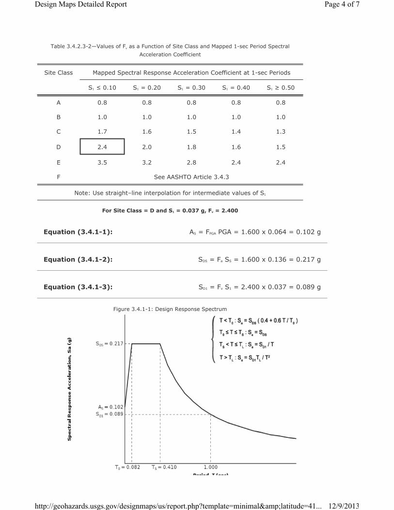
Equation (3.4.1-1):
Equation (3.4.1-2):
Equation (3.4.1-3):
Table 3.4.2.3-2—Values of Fv as a Function of Site Class and Mapped 1-sec Period Spectral Acceleration Coefficient
Site Class Mapped Spectral Response Acceleration Coefficient at 1-sec Periods
S1 ≤ 0.10 S1 = 0.20 S1 = 0.30 S1 = 0.40 S1 ≥ 0.50
A 0.8 0.8 0.8 0.8 0.8
B 1.0 1.0 1.0 1.0 1.0
C 1.7 1.6 1.5 1.4 1.3
D 2.4 2.0 1.8 1.6 1.5
E 3.5 3.2 2.8 2.4 2.4
F See AASHTO Article 3.4.3
Note: Use straight–line interpolation for intermediate values of S1
For Site Class = D and S1 = 0.037 g, Fv = 2.400
AS = FPGA PGA = 1.600 x 0.064 = 0.102 g
SDS = Fa SS = 1.600 x 0.136 = 0.217 g
SD1 = Fv S1 = 2.400 x 0.037 = 0.089 g
Figure 3.4.1-1: Design Response Spectrum
Page 4 of 7Design Maps Detailed Report
12/9/2013http://geohazards.usgs.gov/designmaps/us/report.php?template=minimal&latitude=41...

Page 5 of 7Design Maps Detailed Report
12/9/2013http://geohazards.usgs.gov/designmaps/us/report.php?template=minimal&latitude=41...

Article 3.5 - Selection of Seismic Design Category (SDC)
Table 3.5-1—Partitions for Seismic Design Categories A, B, C, and D
VALUE OF SD1 SDC
SD1 < 0.15g A
0.15g ≤ SD1 < 0.30g B
0.30g ≤ SD1 < 0.50g C
0.50g ≤ SD1 DFor SD1 = 0.089 g, Seismic Design Category = A
Seismic Design Category ≡ “the design category in accordance with Table 3.5-1” = A
Page 6 of 7Design Maps Detailed Report
12/9/2013http://geohazards.usgs.gov/designmaps/us/report.php?template=minimal&latitude=41...

References
1. Figure 3.4.1-2: http://earthquake.usgs.gov/hazards/designmaps/downloads/pdfs/AASHTO-2009-Figure-3.4.1-2.pdf
2. Figure 3.4.1-3: http://earthquake.usgs.gov/hazards/designmaps/downloads/pdfs/AASHTO-2009-Figure-3.4.1-3.pdf
3. Figure 3.4.1-4: http://earthquake.usgs.gov/hazards/designmaps/downloads/pdfs/AASHTO-2009-Figure-3.4.1-4.pdf
Page 7 of 7Design Maps Detailed Report
12/9/2013http://geohazards.usgs.gov/designmaps/us/report.php?template=minimal&latitude=41...
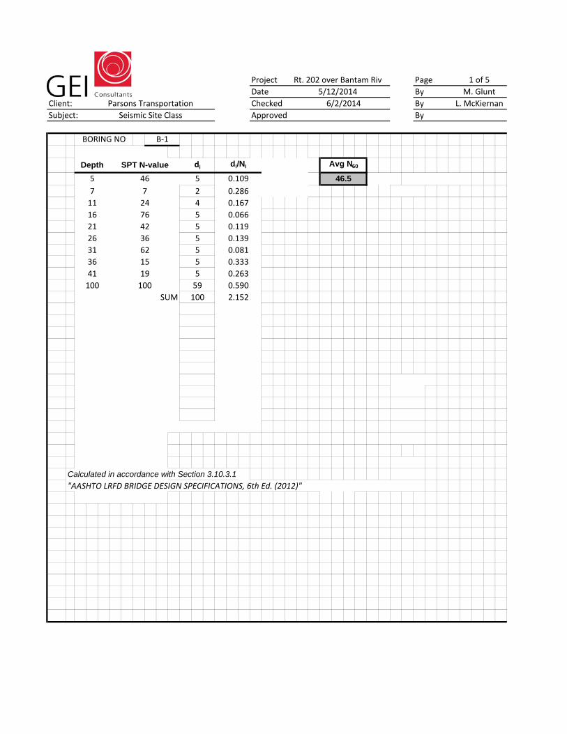
Project PageDate By
Client: Checked BySubject: Approved By
Calculated in accordance with Section 3.10.3.1
"AASHTO LRFD BRIDGE DESIGN SPECIFICATIONS, 6th Ed. (2012)"
36
41100
19100
7642
SUM
1 of 5M. Glunt
L. McKiernan
100
di/Ni
0.1090.2860.1670.0660.1190.1390.0810.3330.2630.590
46.5
Avg N60
BORING NO B‐1
Rt. 202 over Bantam Riv5/12/20146/2/2014
2.152
di52455555559
6215
724
Parsons TransportationSeismic Site Class
Depth
57111621263136
SPT N-value
46
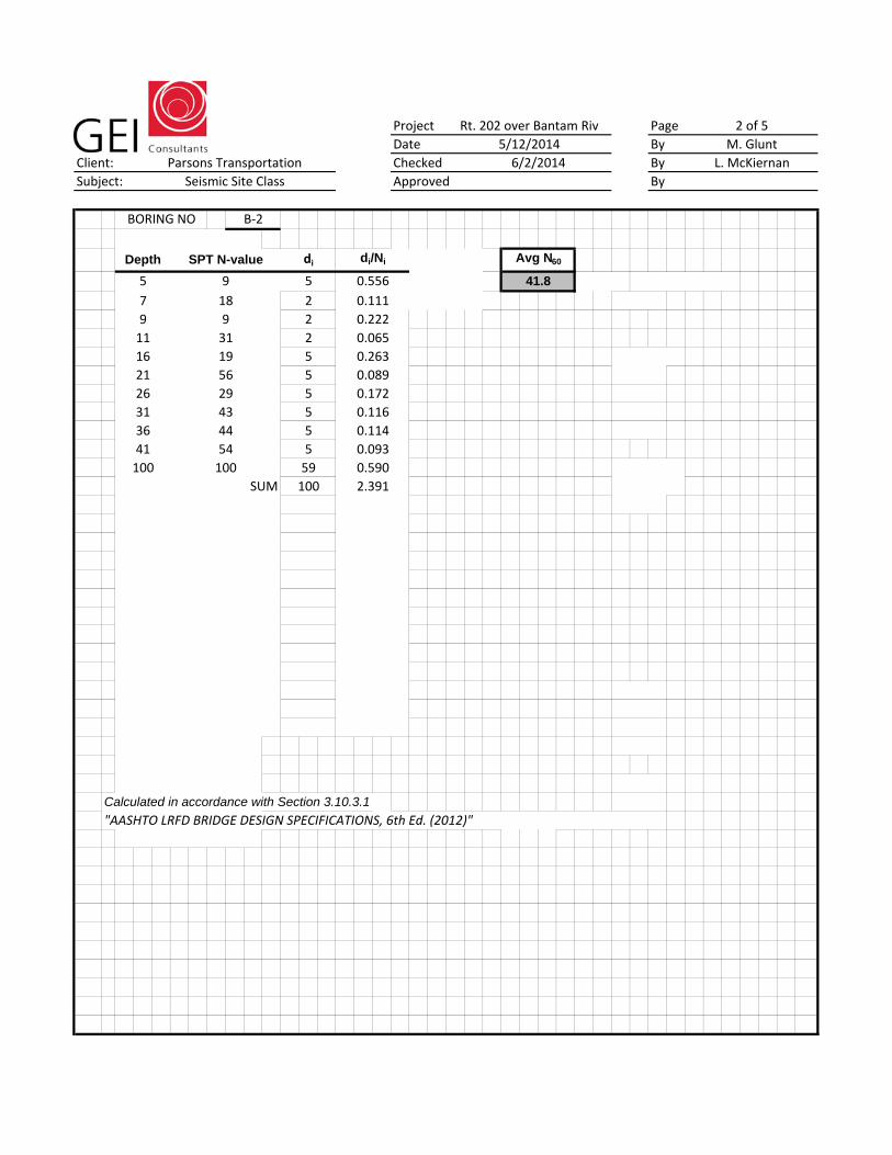
Project PageDate By
Client: Checked BySubject: Approved By
Calculated in accordance with Section 3.10.3.1
9 9 2 0.222
5 9 5 0.556 41.8
7 18 2 0.111
BORING NO B‐2
Depth SPT N-value di di/Ni Avg N60
2 of 55/12/2014 M. Glunt6/2/2014 L. McKiernan
Rt. 202 over Bantam Riv
11 31 2 0.06516 19 5 0.26321 56 5 0.089
31 43 5 0.11626 29 5 0.172
36 44 5 0.114
SUM 100 2.391
41 54 5 0.093100 100 59 0.590
Parsons TransportationSeismic Site Class
"AASHTO LRFD BRIDGE DESIGN SPECIFICATIONS, 6th Ed. (2012)"
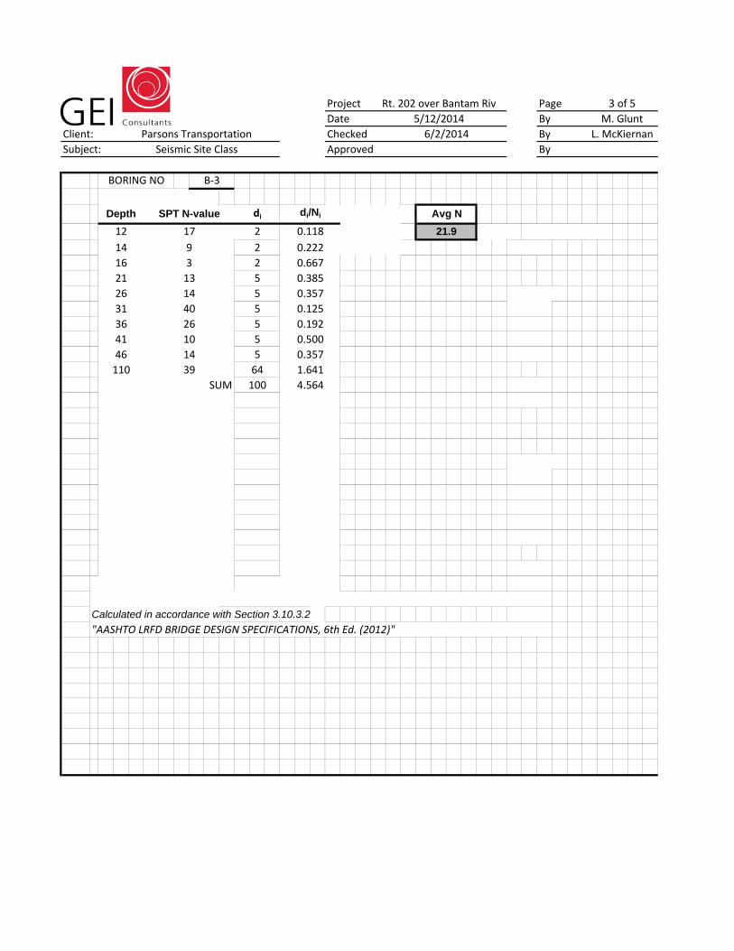
Project PageDate By
Client: Checked BySubject: Approved By
Calculated in accordance with Section 3.10.3.2
Rt. 202 over Bantam Riv 3 of 55/12/2014 M. Glunt6/2/2014 L. McKiernan
BORING NO B‐3
Parsons TransportationSeismic Site Class
Depth SPT N-value di di/Ni Avg N
16 3 2 0.667
12 17 2 0.118 21.9
21 13 5 0.38526 14 5 0.357
14 9 2 0.222
31 40 5 0.12536 26 5 0.19241 10 5 0.50046 14 5 0.357
SUM110 39 64 1.641
"AASHTO LRFD BRIDGE DESIGN SPECIFICATIONS, 6th Ed. (2012)"
100 4.564
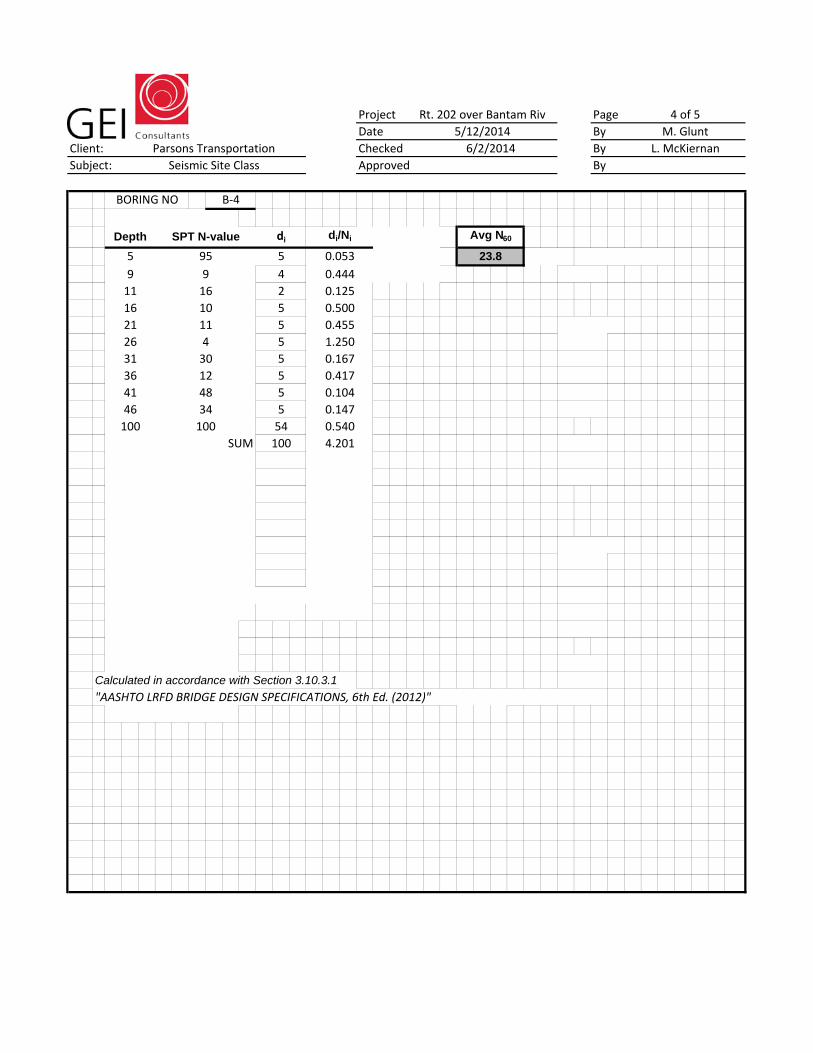
Project PageDate By
Client: Checked BySubject: Approved By
Calculated in accordance with Section 3.10.3.1
Rt. 202 over Bantam Riv 4 of 55/12/2014 M. Glunt6/2/2014 L. McKiernan
BORING NO B‐4
Parsons TransportationSeismic Site Class
Depth SPT N-value di di/Ni Avg N60
11 16 2 0.125
5 95 5 0.053 23.8
16 10 5 0.50021 11 5 0.455
9 9 4 0.444
26 4 5 1.25031 30 5 0.16736 12 5 0.41741 48 5 0.10446 34 5 0.147100 100 54 0.540
"AASHTO LRFD BRIDGE DESIGN SPECIFICATIONS, 6th Ed. (2012)"
SUM 100 4.201
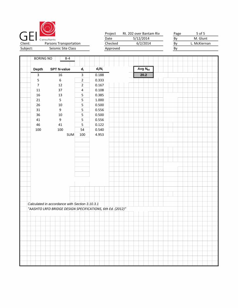
Project PageDate By
Client: Checked BySubject: Approved By
Calculated in accordance with Section 3.10.3.1
"AASHTO LRFD BRIDGE DESIGN SPECIFICATIONS, 6th Ed. (2012)"
46 41 5
SUM 100 4.953
41 9 5 0.556
100 100 54 0.5400.122
31 9 5 0.55636 10 5 0.500
21 5 5 1.00026 10 5 0.500
11 37 4 0.10816 13 5 0.385
5 6 2 0.333
BORING NO B‐4
Depth SPT N-value di di/Ni Avg N60
7 12 2 0.167
3 16 3 0.188 20.2
Rt. 202 over Bantam Riv 5 of 55/12/2014 M. Glunt6/2/2014 L. McKiernanParsons Transportation
Seismic Site Class