0 Safety A Handbook S H - North Slope Training Cooperativenstc.apicc.org/download/19.pdf · Eni...
210
2010 Alaska Safety Handbook ConocoPhillips Alaska Eni Petroleum ExxonMobil Pioneer Natural Resources Alaska Shell Exploration & Appraisal 2 0 1 0 A S H
Transcript of 0 Safety A Handbook S H - North Slope Training Cooperativenstc.apicc.org/download/19.pdf · Eni...

2010
AlaskaSafetyHandbook
ConocoPhillips AlaskaEni Petroleum
ExxonMobilPioneer Natural Resources Alaska
Shell Exploration & Appraisal
2
0
1
0
A
S
H

Printed in Alaska by Q L Printing

i
Dear Employee:
ConocoPhillips Alaska, Inc.; Eni Petroleum; ExxonMobil; Pioneer Natural Resources Alaska; and Shell Exploration & Appraisal have been working to standardize safety procedures in our operations. This publication is a product of that effort.
Our goal is to provide each of you with a safer workplace by identifying and implementing “best” safety practices, by giving all employees and contractors a single set of safety rules and by insisting on uniform application of these safety procedures and standards.
This Safety Handbook defines standards of conduct that must guide our day-to-day efforts. It explains your safety responsibilities and the responsibilities of your co-workers. We expect you to understand and use these safety rules while on the job. It is a requirement of employment. Compliance with these safety rules is also an obligation to your coworkers, to your family, and to yourself.
Please contact your supervisor if you have any questions regarding this handbook or how the standards and procedures it contains will be implemented in your area.

ii
TABLE OF CONTENTSPHONE NUMBERS .......................................................... v
SAFETY – GUIDING PRINCIPLES ................................. 1
SUPERVISOR SAFETY EXPECTATIONS ....................... 2
INDIVIDUAL SAFETY EXPECTATIONS .......................... 3
SAFETY INFRINGEMENT POLICY ................................. 4
SAFETY GUIDELINES AND PROGRAMS ..................... 5 General Safety Rules ................................................... 5 Industrial Hygiene (IH) Program .................................. 8 Process Safety Management (PSM) ........................... 9 Office and Camp Safety ............................................... 9 Fire Protection ............................................................. 11
EMPLOYEE SAFETY ....................................................... 14 Personal Protective Equipment (PPE) ......................... 14 Cold Weather Protection Guidelines ............................ 17 Cold Related Injuries ................................................... 17 Housekeeping Practices ............................................... 18 Fall Protection Requirements / Procedures ................. 19 Working Over or Near Water ........................................ 21 Smoking ....................................................................... 21
EQUIPMENT SAFETY ..................................................... 22 Electrical Hazards & Requirements ............................. 22 Steam Hazards and Guidelines ................................... 24 Barricade Guidelines ................................................... 26 Ladder Safety .............................................................. 27 Tool Usage ................................................................... 28 Cutting Tools ................................................................ 29 Cam & Groove Fittings................................................. 29 Materials Storage......................................................... 30 Scaffold Requirements ................................................ 30 Structures (Portable/Temporary) .................................. 31
HEAVY EQUIPMENT SAFETY ........................................ 32 General Rules of Operation ......................................... 32 Mobile Crane/Side Boom Practices ............................. 33 Rigging/Lifting .............................................................. 34 Low Temperature/High Wind Operation ....................... 35

iii
COMPRESSED GAS CYLINDERS ................................. 38 Cylinder Handling ........................................................ 38 Cylinder Use ................................................................ 39 Cylinder Storage/Maintenance .................................... 40
FLAMMABLE LIQUIDS AND OTHER HAZARDOUS MATERIALS ........................................... 41 General Rules .............................................................. 41 Radiation Safety .......................................................... 42
TRANSPORTATION ........................................................ 43 Vehicle Safety .............................................................. 43 Safe Driving Rules ....................................................... 44 Disabled Vehicle .......................................................... 46 Four-Wheeler or Snow Machine Travel ........................ 47 Foul Weather Contingency Plans................................. 47 Helicopter Travel .......................................................... 48 Helicopter Travel Offshore ............................................ 49 Fixed Wing Aircraft Travel ............................................ 49 Crew Boat Operations ................................................. 50 Material/Personnel Transfer between Offshore Platforms and Boats ................................................. 51
SAFETY STANDARDS AND PERMITS, REQUESTS ..... 53 Introduction .................................................................. 53 Titles ............................................................................ 53 General Permitting Rules ............................................. 55 Site Specific Permitting Guidelines .............................. 58 Unit Work Permit .......................................................... 60 Unit Work Standard ................................................. 63 Hot Work Permit ........................................................... 69 Hot Work Standard .................................................. 72 Confined Space Entry Permit ...................................... 81 Confined Space Entry Standard ............................. 84 Master Card / Energy Isolation List Form .................... 99 Worker Log ................................................................. 100 Energy Isolation Standard ...................................... 101 Lockbox Lockout Flow Chart ....................................... 117

iv
Process Opening / Blinding Work Permit ......................... 118 Process Opening / Blinding Standard .................... 121 Tags (Danger/Caution/Abandoned) ............................ 127 Tagging & Flagging Standard ................................. 134 Defeated Safety Device Log ....................................... 137 Defeated Safety Devices Standard ........................ 138 Area Civil Work Request ............................................. 140 Excavating, Trenching, and Drilling Standard ........ 142 Snow Removal Standard ............................................ 147 Application for Overload Permit .................................. 151 Oversize Vehicle Standard ..................................... 152 Hydrogen Sulfide (H2S) Standard .............................. 155 Iron Sulfide ............................................................. 158 Structural Penetration Standard .................................. 159 Impedance Pipe Thaw Standard ................................. 161 Hot Tapping and On-Line Plugging of Equipment in Service Standard .................................................... 163 Flammable and Combustible Fluid Transfer Standard ................................................................. 165 Hydrostatic Testing Standard ...................................... 169 Fired Heater Standard ................................................ 173 Safety Standard Variance Form .................................. 178 Variance to Safety Standard .................................. 179
TABLE 1 – Wind Chill Chart .......................................... 180
TABLE 2 – ANSI Flange Pressure Rating .................... 181
CONVERSION FACTORS ............................................... 182
WATER PRESSURE TABLES ........................................ 186
RIGGING TABLE ............................................................. 188
GLOSSARY..................................................................... 189
INDEX .............................................................................. 196
SAFETY HANDBOOK AMENDMENT PROCEDURE .............................................................. 199 Alaska Safety Handbook Amendment Form ............... 200

v
Phone Numbers
ConocoPhillips Alaska, Inc.
AnchorageEmergency 9-911
Security Control Room (Emergency) 265-6150
Security Control Room (Non-Emergency) 265-6630
Kiosk 265-6235
Building Maintenance 265-6944
Safety/Training 263-4889/263-4745
ConocoPhillips Alaska, Inc. Hotline 263-4500
Family Emergency Information Line 265-1000
Alaska Regional Hospital 276-1131
Providence Hospital 562-2211
BelugaEmergency 911
Operations Supervisor 263-3930
Safety 776-2030
Environmental 776-2092
Central Peninsula General Hospital 262-4404
Nikiski Paramedics 776-8200
KuparukEmergency 659-7300
Security 659-7997
Environmental 659-7242
Spill Response Coordinator 659-7997
Safety 659-7593
vi
AlpineEmergency 911 or 670-4900
Safety 670-4756
Environmental 670-4200
Spill Response 670-4002
Emergency Services Assistant Chief 670-4752
Security 670-4704
Medic (Non-Emergency) 670-4100
Industrial Hygiene 659-7812
Weather 670-2210
Paging 670-4930
Cook InletEmergency 911
Safety 776-2030
Environmental 263-4619
Operations Manager 776-2021
Tyonek Office 776-2073
Tyonek Control Room 776-2075
Central Peninsula General Hospital 262-4404
Nikiski Paramedics 776-8200
Alyeska PipelinePump Station 1 659-2637
vii
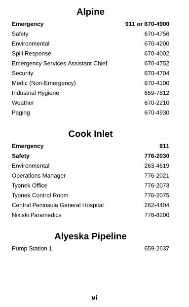
BP Exploration (Alaska) Inc.
AnchorageEmergency 9-911 or 564-5111
Security Control Room (Non-Emergency) 564-5954
BadamiEmergency 911/659-1200
EndicottEmergency (on-site Direct Dial) 911 / 6900
Emergency (off-site or Cell) 659-6900
Milne PointEmergency (On-site) 911
Emergency (from off field, or cell) 670-3399
North StarEmergency (On Island) 911
Emergency (Off Island) 670-3500
Greater Prudhoe BayEmergency (On-Site) 911
Emergency Dispatch 659-5631
Gas to LiquidsEmergency (On-Site) 911
Main 776-5413

viii
ENIOCC
Emergency 670-8500Main 670-8531
AnchorageMain 852-3300
ExxonMobilPoint Thomson
PTP Deadhorse Pad Emergency 670-8917PTP Central Pad - Primary Emergency 433-3575PTP Central Pad - Secondary Emergency 670-1131
Pioneer Natural Resources AlaskaAnchorage
Emergency 9-911Main 277-2700
Pioneer Natural Resources AlaskaOooguruk
Emergency 670-6500Medical 670-6611Safety 670-6622Environmental 670-6625Spill Response 670-6623Offshore Security/Medic 670-6676Onshore Security/Medic 670-6598Offshore Control Room 670-6642Onshore Control Room 670-6501Operations Supervisor 670-6530Drilling Supervisor 670-6606
Shell UA Exploration & AppraisalAnchorage
Emergency 382-4130 306-8016Journey Management Group 771-7233Main Office 770-3700

1
SAFETYSafety is identifying and eliminating or minimizing occupational safety and health risks. Management has the principal respon-sibility for safety, and all employees and contractors share an obligation for safety.
Guiding Principles
• Injuries and occupational illnesses are preventable.
• Safety is fundamental to the conduct of our business.
• Employee involvement, feedback, and recognition are fundamental to safety.
• Safe behavior is doing the job right.
• Workplace risk will be reduced in the following priority:
1. Engineering controls;
2. Administrative controls and operating practices;
3. Personal protective equipment.
• Management is responsible for visibly and consistently establishing safety as a core value.
• Management is responsible and accountable for the safety of employees, contractors, and the general public.
• Employees and contractors are responsible and account-able for their actions.
• Employees and contractors have an obligation, with-out fear of reprisal, to notify management of apparent hazards, and they have the right to receive timely and adequate responses.
2
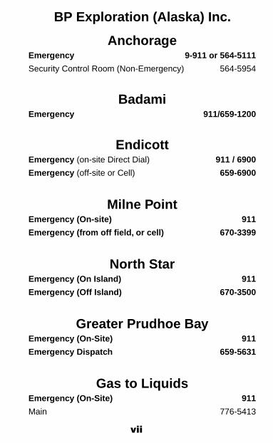
SUPERVISOR SAFETYEXPECTATIONS
The Supervisor is responsible for the safety of the operation. Production goals will be accomplished with safe operations. The Supervisor is expected to:
• Set an example for employees to follow.
• Know the job and have a thorough knowledge of the hazards associated with each operation.
• Communicate safe work practices to each employee.
• Hold and document periodic safety meetings.
• Thoroughly and promptly investigate and report all injuries, near misses, and incidents, and ensure that corrective action has taken place.
• Perform daily safety surveys to ensure that safe conditions exist and that safe practices are being followed.
• Ensure that employees know to report all injuries and unsafe conditions or practices.
• Know, support, and inform employees of Company policies and procedures.
• Ensure that all new employees receive a safety orientation prior to reporting to any work assignment.
• Ensure that all employees receive applicable training in the work practices necessary to safely perform their work.
• The supervisor can delegate their Signature Authority to a Designee for permitting duties. The individual delegating the authority remains ultimately responsible.
3
INDIVIDUAL SAFETYEXPECTATIONS
The success of any safety program is based upon the individual having a positive attitude toward safety and injury prevention. The individual is expected to:
• Be responsible for the safe performance of the job, both for your personal safety and that of fellow workers. This includes the proper use of personal protective equipment, safety equipment, and adhering to safe work practices.
• Report promptly every injury, near miss, and incidence of fire, equipment or property damage to your Supervisor.
• Take necessary actions to stop or correct unsafe behav-iors or conditions and, if appropriate, report them to your Supervisor.
• Actively participate in safety meetings.
• Assist in the investigation of incidents as requested by the Supervisor.
• Become familiar with the contents of this Safety Hand-book, Company policies, and pertinent standard or safe operating procedures.
• If a work situation arises that is not covered by this Hand-book, consult your supervisor.

4
Safety Infringement PolicyIt is Company policy that employees and contractors will work safely at all times. There are times when disciplinary action is appropriate to ensure the business operates in a safe and professional manner.
Working safely is a condition of employment. Employees who fail to observe proper standards of conduct, or who willfully violate Company rules and/or act in an unsafe manner, will be subject to appropriate disciplinary action, which may include dismissal at the discretion of the Company.
For details of the safety infringement policy, please refer to the appropriate existing Company or Contractor Company HR disciplinary policies.

5
Safety Guidelines andPrograms
Note: Always be familiar with site-specific safety requirements.
General Safety Rules
No job is so important that you cannot take time to do it safely.
1. Any Company or contract employee who works unescorted at the various field-operating areas or is North Slope as-signed shall complete, at a minimum, the North Slope Training Cooperative (NSTC) Unescorted Course prior to arrival at their assigned location. Training is available from NSTC-qualified instructors in operator, contractor, and third party provider companies. Any person physically working on equipment or driving Company vehicles would generally require the “unescorted” training requirements regardless of local oversight. On completion of this course, personnel will be issued a signed NSTC card which is required for the issuance of a Company Badge.
2. All non-facility assigned personnel shall get approval and sign in at the facility Control Room or designated location before proceeding into any process area or right-of-way. Contact the facility Control Room for access procedures.
Personnel shall also sign out upon completion of work or whenever leaving the facility.
3. Non-intrinsically safe devices, including cellular phones, personal communication devices, digital music players, radios, radio chargers, flashlights etc., shall not be used or powered up in classified areas.
4. No work shall be started on any equipment without the knowledge and consent of the person responsible for that area.
5. All personnel shall immediately take necessary action to correct any unsafe actions or conditions and, if appropri-ate, report them to the responsible Supervisor.
6. No equipment shall be operated unless the operator has received proper training on that equipment.

6
7. All equipment shall be positioned in such a manner that ensures the equipment’s exhaust does not enter buildings.
8. Compressed air shall not be applied to clothing or personnel.
9. Serious accidents have occurred because the injured personnel were wearing jewelry, loose clothing or long, unrestrained hair. These injuries may have been caused by contact with hazards such as moving machinery, en-ergized electrical systems, hot surfaces, or less obvious events like catching rings when climbing equipment.
The following guidelines are to be followed to prevent injuries whenever working at an operations facility, site or shop area:
• Finger rings, metal-banded wrist-wear, and other conductive items shall not be worn when performing live electrical work.
• Necklaces or medallions shall be removed or tucked inside clothing so as not to create a hazard.
• Rings shall be removed, taped up or gloves worn over if a catching hazard exists.
• Unrestrained long hair shall be controlled whenever working around rotating/moving equipment.
• Precautions shall be taken to ensure loose clothing or accessories do not pose a hazard whenever working around rotating equipment.
10. Fire extinguishers, alarm boxes, fire doors, air packs, eyewash stations, and all other emergency equipment shall be maintained in good working order and kept clear of obstructions.
11. Only compressed air shall be used for pneumatic tools.
12. An atmospheric test must be conducted prior to using pneumatic/hammer wrenches in a classified area.

7
13. For air and ground travel to/from and on the North Slope, personnel shall carry the following from October 1 through May 1 or as weather conditions warrant: heavy coat, warm shoes, hat that covers the ears, and gloves or mittens.
14. Personnel involved in work outside of a facility shall have radios or other means of communication in their posses-sion.
15. Running in work areas, except during an emergency, is prohibited.
16. When ascending or descending stairways, use the handrail, and take one step at a time.
17. Before non-routine work occurs, the Work Leader will be responsible for identifying and communicating potential hazards to all members involved in completing the work.
18. Always know a safe emergency exit path and assembly area from your work location.
19. Fighting and horseplay are strictly prohibited on Company property.
20. Illegal substance and alcohol use or possession is pro-hibited while on Company property. All personnel must notify their Supervisor if taking prescription medication that may inhibit their job performance. Prescription drugs should be kept in the original container.
21. All visitors will adhere to site-specific Personal Protective Equipment (PPE) requirements.
22. Many wells on the North Slope are experiencing subsidence around the wellhead that can lead to surface holes. When working on or near wellheads, be alert for potential gravel subsidence areas. If this occurs, immediately vacate the area and report subsidence locations to the responsible Supervisor for that work area. Restrict access to area until appropriate measures can be taken.
23. If lightning or thunder occurs, suspend all outside activities and immediately seek shelter inside.
24. All hose connections in pressure service will be positively secured.

8
Industrial Hygiene (IH) Program
The goal of the Industrial Hygiene Program is the prevention of worker exposures to harmful agents in the workplace. Key elements are anticipation, recognition, evaluation, and control of workplace health hazards.
The operating companies have established industrial hygiene programs to assure safe, healthful, and productive working environments for all personnel. Details can be found in each Company’s HSE policies, procedures, and HSE management systems. IH services and programs include:
• Pre-job safety and health analysis• Project design review• Management of change review• Workplace surveys and investigations• Ergonomic assessments• Health hazard exposure assessments – chemical, physi-
cal, biological agents• New chemical evaluations• Hazard communication – MSDS systems, chemical in-
ventories• SARA inventory management• Engineering controls evaluation and design• Work practices and administrative controls• Respiratory protection program• Personal protective equipment• Blood-borne pathogens program• Hearing conservation program• Asbestos management program• Laboratory chemical hygiene program• Hydrogen sulfide procedures• Emergency response support• Radiation and naturally occurring radioactive materials
(NORM)• Worker health training• Contractor health and safety coordination and assurance• Exposure task evaluation (ETE)• Toxic Substance Control Act (TSCA)

9
Process Safety Management (PSM)
The objective of the PSM program is to mitigate catastrophic releases of the highly hazardous chemicals defined in the OSHA regulation 29 CFR 1910.119. Company specific pro-grams to address the requirements for PSM compliance shall be followed for PSM covered processes.
Office and Camp Safety
Introduction
In addition to the other procedures/precautions in thisHandbook, the following general safety precautions should be followed when working in an office environment; however, there may be site-specific procedures or requirements for your work location. Check with the local Safety, Health, and Environmental group or Building Operations.
Orientation
Personnel reporting to any Company office/camp complex for the first time shall receive a site safety orientation.
Precautions
1. All personnel shall be familiar with the location of the fire alarm pull station and fire extinguisher nearest to their workstation or living quarters.
2. All personnel shall become familiar with the appropriate evacuation route(s) and assembly area(s) for their work-station or living area. Evacuation routes for each floor and building area are clearly marked. Use the stairwell closest to your office or living quarters to evacuate.
3. During fire alarms, Floor Wardens/Security Officers shall make last-minute searches of their areas to ensure all personnel are evacuated. Help the Floor Wardens/Se-curity Officers by clearing the area quickly, and aid them

10
if requested. If a Floor Warden/Security Officer requests you to leave an area, do so! If a door is closed, check carefully for high temperature or smoke before opening. Close all doors on your way out.
4. During evacuation, do not use elevators! Use the stairwells, following the exit signs and evacuation drawings. Take your wallet and keys and dress appropriately for current weather conditions. Evacuate to your assigned assembly area.
5. Personnel with a disability/condition that would preclude their ability to evacuate shall inform their Floor Warden or Security. During evacuations, seek shelter in a stairwell and await the arrival of Security or Fire Department personnel for assistance.
6. Become familiar with the proper procedures to follow during any type of emergency and participate in all evacuation/disaster drills.
7. Keep all passageways, entryways, aisles, storerooms, service rooms, and work areas clean, orderly, sanitary, and well maintained, with no obstructions. Eliminate all tripping hazards from the work place. Aisles and hallways should provide unobstructed movement and immediate access for fire protection personnel and equipment.
8. Keep flammable or combustible material and residue to a minimum. Store in approved metal safety cans and storage cabinets. When disposing of flammable, combustible or hazardous material, ensure that all appropriate safeguards and regulations are followed.
9. Report all spills immediately.
10. Erect barricades around hazardous areas. Never disregard them, even though the danger may not be apparent.
11. Safely stack material/boxes (no closer than 18 inches from sprinkler heads). Do not block fire exits, fire extinguishers, electrical control panels, etc.

11
12. File drawers and desk drawers should not be left open. Do not overload top drawers or shelves so that files or bookcases can tip over. Keep heavy files in lower drawers. Secure file cabinets and bookcases to wall or each other.
13. To avoid creating an electrical hazard, do not overload circuits. Check with Building Operations prior to acquiring any non-standard office electric equipment (small appli-ances, space heaters, electric kettles, etc.). Routinely check the condition of power cords and plugs.
14. Always use an approved ladder or stool to get articles out of reach from the floor. Do not use a chair or other makeshift device to reach high places.
Fire Protection
Response Procedures
In case of fire, the following procedure should be used:
1. Summon help by whatever means available.
2. Isolate all fuel sources and/or threatened facilities.
3. Do not fight fires beyond the initial stage unless you are trained and equipped to do so as a part of a fire depart-ment/brigade or emergency response team. Do not fight a fire before alerting someone else.
4. Fire fighting should be limited to trained personnel and must be conducted within the limits of the individual’s training and experience.
Suppression Equipment AvailableFire extinguishing methods at Company facilities include but are not limited to:
1. Fire Extinguishers
Some portable fire extinguishers are of primary value on only one class of fire; some are suitable on two or three classes. None are suitable for all five classes of fire.
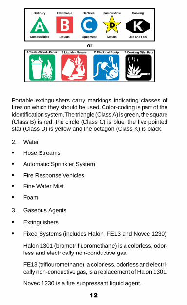
12
Portable extinguishers carry markings indicating classes of fires on which they should be used. Color-coding is part of the identification system. The triangle (Class A) is green, the square (Class B) is red, the circle (Class C) is blue, the five pointed star (Class D) is yellow and the octagon (Class K) is black.
2. Water
• Hose Streams
• Automatic Sprinkler System
• Fire Response Vehicles
• Fine Water Mist
• Foam
3. Gaseous Agents
• Extinguishers
• Fixed Systems (includes Halon, FE13 and Novec 1230)
Halon 1301 (bromotrifluoromethane) is a colorless, odor-less and electrically non-conductive gas.
FE13 (triflouromethane), a colorless, odorless and electri-cally non-conductive gas, is a replacement of Halon 1301.
Novec 1230 is a fire suppressant liquid agent.
B Liquids . GreaseA Trash . Wood . Paper C Electrical Equip K Cooking Oils . Fats
or
KOrdinary
Combustibles
Flammable
Liquids
Electrical
Equipment
Combustible
Metals
Cooking
Oils and Fats
13
Detection and Suppression Equipment Available
Numerous types of fire, smoke, and gas detectors are installed in Company facilities. Employees are responsible for under-standing the type of detection, suppression and associated alarms in their work and living areas.
Evacuation/Emergency Procedures
All Company facilities have specific emergency and evacu-ation procedures. If you are not sure as to your specific role or action, check with facility management prior to proceeding with any work.

14
EMPLOYEE SAFETYPersonal Protective Equipment (PPE)
Eye and FacePersonnel shall wear eye protection when working in process areas, construction locations or other areas were there is a potential for injury from flying particles, metal sparks, radiation, chemicals, or any other identifiable or suspected eye or face hazard. This shall include while personnel are in vehicles on gravel roads unless otherwise exempted by Company policy.
Activities that create flying particles, such as sanding, scrap-ing, grinding, chipping, buffing and blasting require impact-type goggles and a face shield. Workers within 20’ of others performing these tasks are required to wear the same level of eye protection unless barriers (i.e. welding screens or curtains) are in place to control the exposure.
Prior to removal of eye protection, measures for decontami-nation must be in place whenever activities that create flying particles, such as sanding, scraping, grinding, chipping, buffing and blasting are conducted.
All eye protection must meet the requirements of ANSI Z87.1. Safety glasses shall have side shields.
Personnel may wear contact lenses if the lenses are used in conjunction with approved eye protection equipment.
Personnel shall wear chemical goggles and face shield when handling chemical products that present an eye or face hazard or are present in the immediate vicinity where these materials are being handled. Refer to the MSDS for the materials involved.
Respiratory ProtectionWhen engineering and administrative controls cannot effec-tively control exposure to airborne contaminants, respirators shall be used.
Employees shall use respiratory protection in accordance with their Company’s Respiratory Protection Program.

15
For employees in a Respiratory Protection Program, facial hair must be trimmed (no more than 24 hours beard growth) at all times to prevent interference between the sealing surface of the face-piece and the face, or interference with valve function. Some examples of facial hair that interfere with the respirator’s seal include goatees, large moustaches, and long sideburns.
Head ProtectionPersonnel shall wear hard hats while in process facilities, while performing construction, or in other areas where an overhead hazard is or could be present.
Personnel shall wear hard hats that comply with ANSI Z89.1 “American National Standard – Protective Headwear for Industrial Workers.” These are Class E hard hats. Metal hard hats are not allowed.
Foot ProtectionEmployees shall wear protective footwear when working in process areas or other areas where there is a danger of foot injuries due to falling or rolling objects, objects piercing the sole, or where exposed to electrical hazards.
Protective footwear shall meet the requirements of ANSI Z41 “American National Standard for Personal Protection – Protec-tive Footwear” and any additional standards associated with the person’s job, i.e. chemical exposure, electrical exposure.
Extreme cold weather boots not meeting the ANSI Z41 Standard are permitted in cold weather conditions for those individuals who must work outdoors for extended periods.
Shoes with heels are recommended for personnel whose jobs require them to climb ladders with round rung steps.
Anti-slip devices are recommended for outside work during winter months.
Electrical ProtectionPersonal protective equipment for electrical workers shall comply with 29 CFR 1910.137 and NFPA 70E.
Personnel working on energized circuits of 50 volts or greater shall not wear the following types of fabrics, either alone or in blends: acetate, nylon, polyester, or rayon.

16
Hand ProtectionEmployees shall use appropriate hand protection when hands are exposed to hazards such as skin absorption of harmful substances, lacerations, abrasions, punctures, vibration and chemical or thermal burns.
Hearing ProtectionEmployees shall use hearing protection (earplugs or muffs) when exposed to noise greater than 82 dBA. Double hearing protection (earplugs and muffs) is required when exposed to noise levels exceeding 100 dBA.
Signs will be posted in areas exceeding 82 dBA indicating hearing protection is required, and signs will be posted in ar-eas exceeding 100 dBA indicating double hearing protection (earplugs and muffs) is required.
All employees exposed to noise of 85 dBA or above (82 dBA 12-hour equivalent) on the job will be included in the Company Hearing Conservation Program.
Audiometric testing and screening, noise monitoring and employee training will be conducted in accordance with the Company Hearing Conservation Program.
Protective ClothingEmployees shall wear protective clothing, including arctic gear and fire resistant clothing (FRC), as mandated by a workplace hazard assessment. FRC shall be worn as the outer most gar-ment except when other personal protective clothing is required or appropriate (e.g. chemical resistant suits, disposable pro-tective suits, welders leather, personal flotation devices, etc.).
Chemical protective clothing shall be worn when there is a potential for exposure to chemicals that may cause skin ir-ritation or damage on contact or may exert a toxic effect after absorption through the skin.
High Wind ConditionsFor any outside work scheduled when the wind speed exceeds 40 mph, a Safety Time Out/Task Hazard Assessment should be held to determine if the work is of such a high priority that it should be performed in such conditions.

17
Cold Weather Protection GuidelinesFor any outside work scheduled when the wind chill is in the 5-minute frost bite section of the Wind Chill Chart page 180, a Safety Time Out/Task Hazard Assessment should be held to determine if the work is of such a high priority that it should be performed in such severe conditions.
Cold Related InjuriesOur best defense against cold related injuries is to prioritize and limit our outside work during temperature and wind chill extremes, and to use the correct PPE for any outside work. Pay special attention to protection of the face & head, hands, wrists, and feet. Gloves with gauntlets should be used to prevent exposed skin areas between the jacket and gloves.
HypothermiaHypothermia is the lowering of the body core temperature to the point where it is no longer functioning properly. Symptoms include intense shivering, poor coordination, stumbling, loss of memory, thickness of speech and drowsiness. Hypothermia is insidious, and left untreated, may result in collapse and death.
Dehydration, or the loss of body fluids, occurs gradually in the cold environment and may increase the susceptibility of workers to cold injury due to a significant change in blood flow to the extremities. Warm, sweet drinks and soups should be taken to the work site to provide caloric intake and fluid volume. Taking certain medication or drugs such as nicotine, or caffeine because of their diuretic circulatory effects can increase susceptibility to cold. Workers with a cold, or flu, or certain diseases, such as diabetes, heart, vascular, and thyroid problems may be more susceptible to the winter elements. Becoming exhausted or immobilized, especially due to injury, can speed up the effects of cold weather.
It is important to note that most hypothermia cases are reported during cool weather.
TreatmentPrevent further heat loss, contact emergency services, and transport as soon as possible as directed to a medical facility.

18
FrostbiteFrostbite is the freezing of body tissue. It may range from minor injury (“frost nip”) to complete freezing of an extremity. Untreated frostbitten areas will first become reddened, and then become gray or white, particularly on exposed ear lobes, cheeks, or nose. Left untreated, the skin becomes numb and dead white.Watch co-workers for signs of frostbite.
TreatmentTransport as soon as possible to a medical facility.
Housekeeping Practices1. All passageways, entryways, aisles, stairs, storerooms,
service rooms, and work areas shall be kept: • Clean and unobstructed; • Free of ice, or treated with sand, etc., to prevent slip-
ping injuries.
2. All waste and debris shall be removed from the work area and recycled or disposed of properly.
3. Spills shall be reported and cleaned up promptly in ac-cordance with environmental and safety guidelines.
4. Aisles shall be clear and unobstructed to allow for im-mediate access with fire protection equipment.
5. Cords, cables, or hoses should be routed overhead or underneath the grating rather than across doorways or walkways.
6. The area around buildings and unit operating areas shall be kept clean and free of unnecessary materials.
7. Flammable and combustible liquids in buildings or operating areas shall be kept to a minimum and stored in approved metal containers.
8. Rags or waste containing combustible or flammable ma-terials shall be put into approved metal safety waste cans immediately after use. Waste cans shall be emptied daily.
9. Outside food waste receptacles must have lids and be stored in a manner so as not to attract animals.
10. Inside food waste receptacles shall be emptied daily and kept clean and sanitary.

19
Fall Protection Requirements/Procedures
1. 100% Continuous Fall Protection is required at all times when there is a fall potential greater than 6 feet (1.8m). Each employee on a walking/working surface with an unprotected side or edge which is 6 feet or more above a lower level shall be protected from falling by the use of guardrail systems, safety net systems, or personal fall restraint or arrest systems.
2. Work on roofs with slopes/pitch less than or equal to 4 in 12 (vertical to horizontal) with unprotected sides and edges 6 feet (1.8m) or more above lower levels shall require fall protection such as:
• Guardrail system
• Personal fall arrest system
• Combination of warning line system and guardrail system, personal fall arrest system, or safety moni-toring system
• Safety monitoring system alone, on roofs 50 feet or less in width for the performance of roofing operations.
3. Work on roofs with slopes/pitch greater than 4 in 12 (verti-cal to horizontal) with unprotected sides and edges 6 feet or more above lower levels shall require fall protection in the form of guard rail systems with toe boards, safety net systems, or personal fall arrest systems.
4. Full body harness is required for protection from falls. Body belts are no longer acceptable as part of a personal fall arrest system (exemption: this does not apply to belts used as body positioning devices). Additionally, only locking-type snap hooks shall be used; d-rings and snap hooks shall have a minimum tensile strength of 5,000 pounds.
5. Personal fall arrest systems consist of multiple components including full body harness, lanyard, deceleration device, and anchorage (anchor point).
20
6. An anchorage means a secure point of attachment for lifelines, lanyards, or deceleration devices. Anchorage shall be capable of supporting at least 5,000 pounds per employee attached; or as part of a complete personal fall arrest system that maintains a safety factor of at least 2 and is operated under the supervision of a qualified person.
7. Guardrails, electrical conduit, floor grating, scaffold mem-bers, and fire suppression piping shall not be used as an anchorage for a personal fall arrest system. Scaffold erection crews may be able to tie off to scaffold members if no other anchor point is feasible. Prior to use, a qualified engineer must approve process piping to be used as an anchorage.
8. Personal fall arrest systems shall limit maximum arresting force to 1,800 pounds and be rigged such that an employee can neither free-fall more than 6 feet (1.8m) nor contact any lower level.
9. Lanyards and vertical safety lifelines shall have a minimum breaking strength of 5,000 pounds. Each employee shall be attached to a separate vertical lifeline.
10. Lanyards shall not be tied back to themselves unless the lanyard is specifically designed and rated by the manu-facturer for this configuration.
11. Horizontal lifelines for fall protection applications shall be designed, installed, and used under the supervision of a qualified person as part of a complete personal fall arrest system.
12. Personal fall arrest systems shall be inspected prior to each use for wear, damage, and other deterioration. Defective components shall be removed from service.
13. Personal fall arrest systems and components subjected to impact loading shall be removed from service immediately.
14. Positioning device systems shall be rigged such that an employee cannot free fall more than 2 feet (0.9m) and be secured to an anchorage capable of supporting at least twice the potential impact load of a fall, or 3,000 pounds, whichever is greater.

21
Working Over or Near Water
1. Employees working over or near water where the danger of drowning exists shall be provided with U.S. Coast Guard-approved life jacket or buoyant work vests.
2. Prior to and after each use, the buoyant work vests or life preservers shall be inspected for defects, which would alter their strength or buoyancy. Defective units shall not be used.
3. Ring buoys with at least 90 feet of line shall be provided and readily available for emergency rescue operations. Distance between ring buoys shall not exceed 200 feet.
4. At least one lifesaving skiff shall be immediately available at locations where employees are working over or adjacent to water.
Smoking
In accordance with Company Smoking Policy, smoking is allowed in designated areas only.
All other areas within production, process, drilling, and construc-tion areas are “No Smoking” areas. Refer to the Company’s Smoking Policy for further details.
It is prohibited to use or carry any lighters or matches in any production facility or on a drill site or well pad except in des-ignated smoking areas.

22
EQUIPMENT SAFETYElectrical Hazards & Requirements
1. Only qualified and authorized personnel shall repair, in-stall, or adjust electrical equipment. Operate only those switches that you are trained to use.
2. In addition to FRC, all personnel within the Flash Protection Boundary (reference NFPA 70E) shall use appropriately rated gloves, safety glasses, hearing protection, non-conductive boots, and insulated tools plus Flash Hoods and Flash Jackets.
3. When electric-driven equipment becomes unsafe to oper-ate, it shall be locked and tagged out immediately.
4. A Hot Work Permit is required to install or use non-explosion-proof temporary lighting in a classified area.
5. Inspect all extension cords or plug-connected hand tools for any sign of damage or missing parts prior to use. Tag defective appliances and turn in for repair.
6. All portable electric tools and lights shall be used with ground fault circuit interrupters (GFCI) or be included in an assured grounding program. Low voltage lights may be used in lieu of lights with GFCI.
7. Always maintain the minimum NEC required clearance in front of all switchgear and motor control centers for access (at least 4 feet recommended). If these clearances are not present, the switchgear area must be appropriately marked with warning labels. These spaces must be kept clear and must not be used as a storage area.
When electrical work is required in spaces with restricted clearance, the following shall be adhered to:
a. Equipment in the area should be de-energized; or,
b. If equipment must be kept energized, a safe work plan shall be developed, approved by the responsible Supervisor, and followed.
23
8. Equipment operating within 15 feet of any un-insulated power distribution system line, structure, guy wire or switch yard requires prior clearance by the appropriate Company Supervisor.
9. Only a qualified electrician may bring a conductive object closer than 15 feet to unguarded, energized overhead lines.
10. Only authorized personnel shall be permitted in electrical distribution switchgear rooms and enclosures.
11. Power distribution switchgear shall be operated only by qualified personnel.
12. After a circuit is de-energized by a circuit protective device i.e. circuit breakers, fuses, protective relay device, vfd control panel, etc., the circuit may not be manually re-energized until it has been determined by qualified and authorized electrician that the equipment and circuit can be safely energized. The repetitive manual re-closing of circuit breakers or re-energizing circuits through replaced fuses is prohibited. A 120v lighting panel breaker may be reset once by qualified and authorized person if the trip has been determined that it has been caused by an overload condition.
NOTE: When it can be determined from the design of the circuit and the over-current devices involved that the automatic operation of a device was caused by an overload rather than a fault condition, no examination of the current or connected equipment is needed before the circuit is re-energized.
13. Motor overloads may be reset once after an Operator has checked the motor for any unusual conditions such as hot bearings, motor, etc. Notify facility electrician of the trip.
14. Motor starts per hour shall not exceed the manufacturer’s specifications.
15. Any feeder or branch circuit breaker trips shall be brought to the attention of the Supervisor and facility electrician.
16. Authorized power plant operators may open and close the switchgear used as part of the routine plant operation.

24
17. All electrical work shall be done in accordance with the appropriate edition of:
• National Electrical Safety Code (ANSI C2) • 29 CFR 1910 (Code of Federal Regulations, Occu-
pational Safety and Health) • 29 CFR 1926 Subpart K, Electrical • National Electrical Code (NFPA 70) • Standard for Electrical Safety in the Workplace (NFPA
70E)
18. Any work on energized equipment greater than 50 volts shall follow established Company energized work prac-tices and utilize an Energized Electrical Work Permit. Work performed on or near live parts by qualified persons related to tasks such as testing, troubleshooting, voltage measuring, etc., shall be permitted to be performed without an Energized Electrical Work Permit, provided appropriate safe work practices and personal protective equipment are used.
19. Any work directly on energized circuits (nominal rating 480/277 volts or greater) requires two qualified electrical personnel as defined in your company’s Electrical Safety Program. Work performed on or near live parts such as testing, troubleshooting, and voltage measuring may be accomplished by one qualified electrical person for volt-ages below 600 volts.
20. Electrical cables and/or extension cords should be run overhead, and not laid on the ground or deck.
21. Portable ladders, used for electrical work, shall have non-conductive side rails.
Steam Hazards and GuidelinesEach cleaning or purging application utilizing steam to eliminate a process equipment flammable atmosphere, will require a writ-ten specific procedure that is reviewed by a Facility Engineer and a Company Safety Representative and agreed upon by the owner of the equipment and the group responsible for the execution of the plan. These procedures must at a minimum address the considerations outlined here.

25
General Safety ConsiderationsPPE considerations need to be assessed to protect workers from burns from hot surfaces or contact with steam.
The exiting steam and waste can form an ignitable mixture once it combines with the outside air. It is important to eliminate ignition sources near the tank/pipe/vessel such as vehicles, heaters, etc. and monitor the wind direction. The steam plume exiting a vessel, tank or pipe can contain high level of hydro-carbons including benzene. Caution must be used to ensure that employees, offices, or air intakes are not in the path of the plume. Always place barricades and or visible signs as needed.
Follow the ASH Fired Heater Standard guidelines for staging and setting up the fired steam generator unit.
Contraction and expansion must be considered for all types of equipment and coatings due to rapid temperature changes. This can affect tanks, vessels, or pipelines. The way equipment is secured and allowed to move must also be considered. This is especially true when using both steam and nitrogen to purge systems.
Consideration needs to be given to the possibility of heating NGLs within vessels or pipelines. Once heated, NGLs can produce large amounts of vapor. It is a good practice to flush equipment with diesel prior to steaming so that the NGLs are diluted, producing a less volatile mixture.
Ensure that the steam nozzle and tank/vessel are bonded together and grounded to prevent static discharge during operations.
Follow all energy isolation procedures to prepare the equip-ment for cleaning or purging.
Environmental ConsiderationsAll solid and liquid waste streams should be managed and disposed of in accordance with the Alaska Waste Disposal and Reuse Guide (Red Book) guidelines. Some waste streams may require sampling and lab analyses to determine the proper disposal option. Environmental should be contacted prior to generation of wastes.
26
Appropriate spill prevention procedures should be developed and implemented prior to any steaming operation. All spills must be reported per Company procedures.
The force of the exiting steam may produce misting containing hydrocarbon residue. Provisions for mist containment must be considered:
If a tank is to be steamed it must be determined if the tank is a double walled tank. It is critical that there be a vent between the inner and outer wall of the tank. Usually this vent is located on the upper outer wall of the tank. If no vent is located on the tank, steaming cannot be preformed as severe damage to the tank could result. If it is deemed that repairs to the tank walls need to be preformed additional atmospheric testing must be done inside the tank and in the space between the inner and outer wall.
Barricade Guidelines1. Always erect barricades around hazardous areas. Post a
highly visible sign at the barricade identifying the hazard.
2. Permission for entry into barricaded areas must be granted by person in charge.
3. Identify any opening or gate used for egress.
4. Appropriate lighting shall be provided at all times.
5. Mark open holes or excavations well to adequately warn personnel in the event the hazard should later be filled or covered with snow.
6. Temporary floor openings, manhole openings and trapdoor floor openings without covers shall be guarded by remov-able railings when not constantly attended by someone.
7. During well servicing operations, adjacent unprotected wellheads shall be barricaded to prevent inadvertent contact with moving equipment.
8. Temporary wall openings shall be guarded where there is a drop of more than 4 feet.
27
Ladder Safety1. Select the right ladder for the job. • The side rails of through or side-step ladders shall
extend at least 36 inches above the top of the landing platform.
• The use of wooden ladders is prohibited. • Make certain the ladder is strong enough for its in-
tended use by reviewing the load rating on the ladder. • Choose a ladder that is long enough to ensure work
can be done safely.
2. Inspect the ladder before you use it. • Look for loose or damaged rungs, steps, rails, braces
missing screws, hinges, bolts, nuts or other hardware. Report deficiencies to your Supervisor, and remove from service.
• Ensure straight ladders have safety feet. • Never use a defective ladder.
3. Using Ladders: • Use a barricade or guard to prevent unexpected col-
lisions. Lock or block any adjacent door. • When blocking an emergency exit, ensure the ladder
is continually attended. Whenever the worker leaves the area, clear the emergency exit path.
• Keep the area around the ladder base uncluttered. • Avoid tilting by resting your ladder base on a solid,
level surface. • Ensure stepladders are fully open and spreaders are
locked before use. • Position a straight ladder at a 4 to 1 ratio. That means
the base of your ladder is 1 foot away from the wall or other vertical surface for every 4 feet of the ladder’s height to the upper support point.
• When using a ladder to climb onto a roof or platform, allow the ladder to extend at least 3 feet beyond the roof edge or other support point.
• To avoid shifting, secure the ladder by holding or tying down straight ladders as close to the support point as possible.
• Never lean a ladder against an unstable surface.

28
• When working from a ladder: - (6’ or greater) fall protection is recommended when
feasible. - Only reach or lean so that your belt buckle remains
between the ladder rails. - Maintain your balance by centering the body
between the ladder rails.
• When moving ladders 8 feet or greater in length through any process area, consider using two people to prevent inadvertant contact with equipment and possible soft tissue injury.
4. Climb and descend ladders cautiously. • Face the ladder and use both hands. • Carry tools in a tool belt, or raise and lower them with
a hand line. • Check ladder rungs and the bottoms of your shoes
for slippery substances. • Do not climb higher than the second tread from the
top on a stepladder or the third rung from the top on a straight ladder.
• Climbing devices, cages or platforms are required for fixed ladders over 20 feet in height. Use the ladder-climbing device if provided.
5. Ladder storage.
• Do not store ladders in aisle ways. • Do not leave ladders stored unsecured.
Tool UsageMany accidents associated with tool use can be prevented if the following rules are observed:
1. Keep all tools in good condition.2. Inspect coupling, hoses and hose connections of pneu-
matic tools each time you use them. Make sure they are in good condition and properly attached. The use of hose whip checks is highly recommended.
3. Disconnect electric and air tools from their power source when using the chuck key or when not in use.

29
4. Keep grinding wheels in good operating condition. The gap between the grinding wheel, the tool rest, and the tang must never exceed 1/8 inch. Do not grind on the side of a grinding wheel. Grind only material that is suitable for use with the grinding wheel.
5. Always use the right tool for the job.
6. All fixed and portable tools that are designed to have guards shall have guards in place.
7. Powered hand tools that incorporate a locking mechanism on the control switch or trigger, shall allow for a spring-loaded release of the lock by depressing the control switch or trigger itself. A separate positive on/off switch is prohibited.
Cutting Tools1. Open blade knives (except kitchen knives used for food
preparation) are rarely the most appropriate tool selection for cutting.
2. Each work group/individual shall evaluate all cutting tasks associated with an open blade knife for their respective assignments, determine the most appropriate and safest tool for each task and make sure those tools are available. Refer to your company’s specific policy or procedure for evaluating cutting tasks.
3. For any type of cutting, the following best practices should be implemented:
• Always cut away from the body - Line of fire. • Always wear appropriate hand protection (cut gloves,
etc.) • When possible, use cutting tools that self-retract or
have hidden blades. • Store cutting tools with blades protected from ac-
cidental contact.
Cam & Groove Fittings (Cam locks)1. All fittings and hoses shall be rated for intended service
pressure and assembled by qualified personnel only.
2. Whip checks shall be utilized on all hoses coupled with cam and groove fittings in pressurized service.

30
3. Cam arms shall be positively secured.4. A method of verifying atmospheric pressure must be used
such as bleeder valves or vents prior to disconnecting.5. 0 – 35 psig, gas or liquid service – pre-use inspection
required of hose and fittings.6. 36 – 125 psig, liquid service only – pre-use inspection
required of hose and fittings. New hoses and fittings shall be pressure tested to 125 psig prior to placing in service.
7. >125 psig usage is not permitted for cam and groove fit-tings.
8. Cam and groove fittings shall not be used for steam service.9. Exception: Numbers 1 through 8 do not apply to drylock
fittings.
Materials Storage1. Materials shall be piled or stacked safely.2. Use blocks to prevent material from rolling.3. Cross-tie bags and sacks when stacking, store lumber on
stable foundation and cross-tie at intervals, and use racks or chocks to store pipe or bar stock.
4. Do not lean sheet metal against walls or columns, but store on edge in racks or on sleepers.
5. Do not store stacked material within 18 inches of a sprinkler head.
6. Use or storage of Class “A” materials in classified areas should be kept to a minimum.
Scaffold Requirements1. Scaffolds shall be designed by a qualified person.2. Scaffolds shall be constructed under the supervision of a
competent person and inspected by competent personnel.3. Scaffolds that are to be used shall be inspected for visible
defects before each work shift by a competent person and after any occurrence that could affect the scaffold’s integrity.
4. Scaffolds shall be verified complete and inspected be-fore use by a tagging system. Employees shall not use a scaffold that is not tagged as “Ready for Use” for that day. Precautions listed on the tag will be followed.

31
5. Platforms or stairs constructed of scaffold members and less than 6 feet in height for occupants to access buildings do not require inspection.
6. Work on or from scaffolds is prohibited during storms or high winds unless a competent person has determined that it is safe for employees to be on the scaffold and employees are protected by a personal fall arrest system or wind screens. Wind screens shall not be used unless the scaffold is adequately secured.
7. Never use makeshift arrangements to reach high working areas.
8. Never use a scaffold as a rigging anchor point.9. Ladders shall be installed as soon as scaffold erection
has progressed to a point that permits safe installation and use. Do not use cross-braces as a means of access.
10. A complete guardrail system or fall protection system is required for all scaffolds over 6 feet in height.
Structures (Portable/Temporary)Temporarily locating envirovacs, dry shacks, office trailers, and like structures on pads with operating facilities or other classified areas can potentially pose hazards to either the oc-cupants of the temporary/portable structures or to the process facility and personnel.
Unexpected events from adjacent production areas can impact temporary structures. To determine the safest location in the event of an uncontrolled release, a thorough risk based assess-ment shall be conducted and documented. The risk assessment should consider, but is not limited to the following items listed below, and shall be approved by the area/facility supervisor. • Building/structure occupancy level • Prevailing wind directions • Distance from flares/process and tank or vessel
atmospheric vents • Duration of temporary placement • Adjacent process facility critical work activities • Emergency response capabilities • Required Standoff from operating or process areas • Portable building/structures ignition sources

32
HEAVY EQUIPMENT SAFETYThe operation of heavy equipment such as cranes, graders, dozers, rubber-tired loaders or trucks that are rated over 5 tons Gross Vehicle Weight will only be by qualified equipment operators who are assigned to operate such equipment.
General Rules of Operation:1. The unit will always be operated in accordance with the
manufacturer’s operating instructions.
2. Seatbelts are required to be worn at all times while the vehicle is in operation. Riders/passengers are not allowed to ride in the cab unless the equipment is designed to carry passengers.
3. Equipment operators will always assure themselves that the unit can be operated safely by making a complete functional check of the unit before using it to make a lift or use with a load.
4. Equipment operators are responsible to ensure the work area is free from obstructions or hazards. This includes maintaining the proper clearance for overhead objects.
5. If the continued safe operation of the unit is questionable, the activity shall cease until a time that the concern has been resolved by the Supervisor in charge.
6. The equipment operator shall complete a daily safety checklist for each particular piece of equipment operated.
7. All equipment deficiencies shall be reported to the ap-propriate maintenance group.
8. White lights that illuminate to the rear shall not be used while traveling on roadways, except during snow removal or convoy travel.
9. Forklifts shall travel with forks as close to the floor or roadway as practical.
10. It is not recommended that forklifts be used to transport materials on main roads.

33
Mobile Crane/Side Boom Practices1. Only one properly trained person shall signal a crane
operator.2. The crane operator shall never start machine movement
until the signalman is within sight and hand signals are understood. Obey an emergency stop signal given by anyone.
3. All cranes shall have load charts and boom angle indicators located at the crane operator’s position. Offshore cranes shall have dynamic load charts installed in the cab.
4. All cranes shall have anti two-block devices.5. A weight indicator shall be available to determine the
weight of an unknown load prior to lifting.6. Crane mats or timber pads shall be used under pads, or
on soft unstable surfaces.7. The operator shall be in attendance in the cab any time
there is a load suspended from the hook.8. A written lifting plan is required before making critical lifts.
Consult your company’s lifting policy for the definition of a critical lift.
Examples of critical lifts may include the following; • Multi-crane Lift • Personnel are lifted in a Personnel Basket • Lifts over live process lines • Weight of equipment being lifted is known, calculated
or estimated to be greater than 85% of the rated capacity of the equipment as determined by the load chart.
The plan shall be approved by the Safety Representative and First-Line Supervisor or their designee.
9. Never lift in-service process lines without operations and engineering approval.
10. Cranes with booms extended across process lines shall not be left unattended.
11. Man-baskets or other personnel lifting devices shall be used as a last resort and only after completing a preloaded trial lift.
12. Lifting operations where contact with overhead power lines is possible require a written lifting plan.

34
Rigging/Lifting1. Prior to making any lift, determine the weight of the object
to be lifted, the center of gravity of the object, and the best attachment points and methods.
2. Never exceed the capacity of the weakest link in the load path, i.e., hoisting equipment, sling, shackle, turnbuckle, or shouldered eyebolt.
3. All cranes shall be inspected and tested at regular in-tervals according to accepted codes and requirements. Every crane shall be given a basic functional test prior to use. All cranes that are in regular service are required by OSHA to have a frequent (30 day) and periodic (annual) inspection by a qualified and designated person.
4. Cranes that have not been inspected at regular intervals shall not be used until a qualified person has completed an inspection and returned the crane to service.
5. All hoisting equipment shall have the working load limit posted on the bridge, monorail, and other primary com-ponents.
6. Rigging and signaling shall be done only by competent personnel.
7. Never rig from process lines without operations and en-gineering approval. Never rig from electrical conduit.
8. Never stand or walk under suspended loads. Do not pass suspended loads over people. Suspended loads shall be attended at all times.
9. Tag lines must be attached prior to lifting the load. Hand contact must be avoided unless alternatives have been considered and determined to be impractical.
10. Riding the hook or load is prohibited.
Rigging Accessories and Safe LoadsThe working load limit or rated capacity of a sling varies de-pending upon the type of hitch.
1. In cases where bridle slings or multi-leg lift assemblies with three or more legs are used to lift a load, it should be assumed that the load will be carried by only two legs.

35
2. Do not tie knots in sling chains, rope slings, or wire cables to shorten them. Do not place bolts or other material be-tween links of a chain to shorten or splice it. Never repair chains with bolts or by welding.
3. Decreasing the angle between the sling and the horizontal increases the stress on the sling and the sling capacity is de-rated. Refer to the proper rigging tables for the capacity of slings. The angles shall never be less than 30 degrees.
4. Do not choke a wire rope sling on itself; use a shackle.
5. All hoisting and rigging equipment operated in low tem-peratures (<0° F) may be subject to brittle fractures and must be de-rated according to manufacture specifications.
InspectionsAll slings shall be visually inspected (records not required) each day they are used or prior to use if the sling is not in regular service. A periodic inspection (with records) shall also be made at least annually by a qualified inspector.
Low Temperature/High Wind Condition Operations
ScopeIf the temperature is lower than -35° F (-20° F manlifts, scis-sor lifts, and man baskets only), or the wind, including gusts, is greater than 20 MPH, establish a systematic approach for determining the safe operation of equipment. This guidance shall apply to Company employees and contractors operating on Company premises.
EquipmentThis scope applies to mechanical and hydraulic cranes, sidebooms, loaders, forklifts, manlifts, VSM drill rigs, wireline equipment, coil tubing, E-line units and drilling rigs. This type of equipment shall be operated within the constraints of rec-ognized “Good Management Practices” established by the manufacturer’s operating recommendations.
36
These guidelines do not apply to trucks, tractor trailers, vac-trucks or other vehicles used for routine deliveries of materials or equipment, snow removal equipment, etc.
ApplicationOperation of load-bearing equipment and cranes shall be reviewed for equipment limitations at or below ambient tem-peratures and wind velocities as described in the “Scope” section above.
The intent is not to prohibit the use of this equipment at these temperatures, but to carefully review the work, procedures, and equipment limitations.
Official temperatures shall be obtained at the nearest local weather station.
ResponsibilityRegardless of temperature or wind velocity, the on-site respon-sible individual will suspend the lifting operation if personnel or equipment safety is questionable.
The Company Supervisor directing the project or work shall verify with the equipment operator that the lifting equipment is rated and certified by the manufacturer for services below the existing ambient temperature and is in compliance with established contractor or unit fleet guidelines.
Any special safety precautions to be taken as a result of the weather conditions will be addressed at a meeting conducted and attended by the Equipment Supervisor or his designee, the Work Area Supervisor and the lifting equipment operator.
Individual departments may develop operating guidelines that are more restrictive than those in this document.
Review CriteriaWhen evaluating the safety of work at temperatures below the manufacturer’s recommended operating guidelines, the following shall be reviewed:

37
• Hydraulic fluid – ensure that the grade of hydraulic fluid is appropriate for use in the low temperature Arctic environ-ment.
• Pre-operational inspections shall be completed in accordance with manufacturer recommendations and shall be documented. Special attention should be placed on all hoisting mechanisms, including wire ropes and associated rigging. Any special preparations identified by the manufacturer for operating load-bearing equipment in low temperatures shall also be documented.
• Prior to performing work, a 20-30 minute warm-up period for the equipment shall be conducted. This allows a check of all moving components and ensures that appropriate hoses and seals are flexible.
Drilling RigsNormal drilling operations are not affected by the low tempera-tures due to insulated enclosures. However, these guidelines will apply during a rig move and lowering and raising the rig mast.
DocumentationLow temperature or wind velocity operating limitations/special procedures will be documented.

38
Compressed GasCylinders
Safe Handling, Use and Storage
Cylinder HandlingPersonnel whose jobs require the handling of cylinders under pressure shall observe the following safety rules.
1. When moving cylinders the valves shall be closed, use a cart, carrier, or get help. Cylinders with regulators at-tached shall be secured and moved on a special hand truck, otherwise the regulators shall be removed and valve-protection caps installed prior to moving.
2. Cylinders moved by a crane or derrick must be secured in a basket or similar device. Use of slings or ropes wrapped around the cylinder is prohibited.
3. Never drop cylinders or let them strike each other violently.
4. Never use cylinders for rollers, supports, or for any purpose other than to contain gas.
5. Compressed gas cylinders must be legibly marked for the purpose of identifying the gas content, either by chemical or trade name.
6. Empty cylinders must be marked “empty” or “MT” with a wired tag or stick-on label. Valves must be closed tightly and the valve protection cap installed. Do not write on sides of cylinders with chalk or markers.
7. Secure cylinders in an upright position to prevent move-ment during transportation.
8. Valve protector caps shall not be modified or used to lift cylinders.
9. Never store bottles of compressed nitrogen in confined unventilated area.
10. Do not transport nitrogen bottles in a vehicle in which the driver’s cab is not segregated from the storage area.

39
Cylinder UseNo one shall connect/disconnect or operate fuel/gas equipment or apparatus unless they have received proper training on that equipment. There are inherent hazards associated with connec-tion, disconnecting and use of regulators and cutting devices.
1. Fuel gas cylinders shall be used in an upright position. All cylinders shall be secured to prevent movement.
2. Valve protector caps shall be kept on cylinders at all times, except when in service.
3. Threads on a regulator or union shall correspond to those on the cylinder valve outlet. Do not force or modify con-nections.
4. Never use a cylinder of compressed gas without a pres-sure-reducing regulator attached to the cylinder valve or manifold header.
5. Use the regulators and pressure gauges only with gases for which they are designed and intended.
6. Always close the cylinder valve before attempting to stop leaks between the cylinder and regulator.
7. Leaky cylinders shall not be used. If cylinders are found to have leaky valves or fittings which cannot be stopped by closing of the valve, the cylinder shall be taken outdoors away from sources of ignition and slowly emptied and tagged.
8. When transporting SCBA and Skat Paks in vehicles, make sure they are in a proper carrying case.
9. Never permit sparks, molten metal, electric currents, exces-sive heat or flames to contact cylinders or attachments.
10. Never use oil or grease as a lubricant on valves or attach-ments to oxygen cylinders.
11. Do not handle oxygen equipment with oily hands or gloves.
12. Compressed gas cylinders, with the exception of breathing air, fire extinguishers, and small volume aerosol cans (for example, dye penetrant), shall not be taken into Confined Spaces.
40
13. All oxygen/acetylene cutting torches shall have a flashback arrestor installed in each regulator, and a check valve installed on each torch/hose connection. No one shall tamper with the safety devices in cylinders or valves.
14. Never use nitrogen instead of compressed air (for instance with pneumatic tools).
Cylinder Storage/Maintenance1. Oxygen cylinders shall not be stored within 20 feet of
combustible gas cylinders or near any other substance where an accelerated fire could result, unless protected by a wall at least 5 feet high having a fire resistance rating of at least 30 minutes.
2. Cylinders shall be secured and stored in a safe, well-ventilated place that provides adequate protection from the elements.
3. Smoking and other sources of ignition are prohibited.
4. Empty and full cylinders shall be stored separately with empty cylinders plainly identified to avoid confusion.
5. Secure cylinders with chain, cable, or wire. Do not use rope. Do not secure cylinders to process lines.
6. Ensure all gas cylinders are secured in an upright position before performing any maintenance activities on them.
7. Small compressed gas cylinders cannot be stored in flammable lockers that contain flammable liquids.

41
Flammable Liquids andOther Hazardous
MaterialsAlways refer to the MSDS, New Chemical Review Request or New Chemical Evaluation before handling any new chemical. Prior to ordering any new chemicals, contact your Industrial Hygiene Department.
General Rules1. When handling or sampling corrosives, flammables, gases,
poisons, and other hazardous materials, use appropriate goggles, gloves, face shield, apron, respirator, and other necessary personal protective equipment. Safety glasses shall not replace goggles when handling hazardous materials.
2. A safe means of egress shall be maintained at all times when working with hazardous materials.
3. Know the location of safety showers, eyewash stations, and other safety equipment prior to starting work.
4. Use sample containers compatible with the type of product collected and potential pressure.
5. Any receptacle containing flammable liquids (drip cans, secondary containers, buckets, drums, etc.), which could develop a static charge shall be properly affixed with a bonding cable or hose and properly bonded prior to transfer of contents.
6. No flammable fluid transfers shall be started prior to the proper bonding of both receptacles and in accordance with the Flammable and Combustible Fluid Transfer Standard, where applicable.
7. Non-metal secondary containers are prohibited for flam-mable liquids except for Nalgene bottles up to 1 gallon used for taking samples and shakeouts and where required by analytical procedures. Ensure all secondary containers are labeled per the Company Hazard Communication Labeling Program.
42
8. Only personnel who have been trained in the proper handling of hazardous sample containers shall transport these containers.
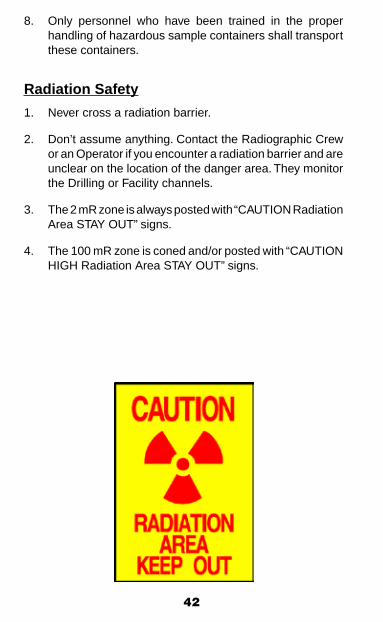
Radiation Safety
1. Never cross a radiation barrier.
2. Don’t assume anything. Contact the Radiographic Crew or an Operator if you encounter a radiation barrier and are unclear on the location of the danger area. They monitor the Drilling or Facility channels.
3. The 2 mR zone is always posted with “CAUTION Radiation Area STAY OUT” signs.
4. The 100 mR zone is coned and/or posted with “CAUTION HIGH Radiation Area STAY OUT” signs.

43
TRANSPORTATIONVehicle SafetyVehicle safety covers all aspects of vehicle operation, includ-ing observing speed limits, passing safely, obeying traffic signs, using seatbelts, safety glasses, yielding right-of-way to emergency vehicles and heavy equipment, remaining at the scene of an accident, and following restricted travel and foul weather procedures.
1. Drivers shall observe all posted speed limits. Drive ac-cording to conditions.
2. Citations shall be issued for traffic violations. The violator’s Supervisor shall be notified and disciplinary action may result.
3. Passengers and drivers in any vehicle equipped with seatbelts are required to wear them while operating or riding in that vehicle as defined in the Company policy. Seatbelts are also mandatory while operating a private vehicle if it is used in the course of Company business.
4. Headlights shall be illuminated whenever the vehicle is being driven.
5. All vehicle accidents shall be investigated. If persons are involved in an accident, they shall immediately notify the appropriate Security Department, or local authorities and their supervisors as soon as possible.
6. A valid driver’s license is required to operate any vehicles or equipment on a lease or right-of-way that would require such a license to be operated on public roadways. If re-quested by Security, you must provide your license within 24 hours of the request.
7. Vehicle and equipment operators and passengers shall wear safety glasses with side shields. When traveling by bus, it is recommended that passengers in the first 4 rows wear eye protection. The driver is required to wear eye protection.
8. Personnel are not allowed to ride on/in truck beds.
9. No equipment shall be operated unless the operator has received proper training and is qualified to operate that equipment.

44
10. All equipment shall be positioned in such a manner that ensures the equipment’s exhaust does not enter buildings or vent intakes.
11. Radar detectors are not allowed in any Company operated vehicles.
12. Use of cruise control is not allowed for North Slope driving.
13. All light duty (pickups, vans, box vans, etc.) vehicles shall have installed an alarm to alert drivers should they try to exit the vehicle while it is in gear and running. Vehicles that do not have this capability shall be secured by ap-propriate means (i.e. wheel chocks, parking brake, etc.) if the driver exits the vehicle while it is running.
14. Parking on drill sites should be done in an organized fashion. Park in the same alignment as the first truck on the pad.
15. A 360 walk around is required before moving the vehicle every time you park and leave your vehicle.
Safe Driving Rules1. Most vehicle accidents are backing related. Drivers should
park to minimize the need to back-up; spotters are required when visibility is limited such that a safe backing path cannot be determined. Reference your local requirements for backing vehicles.
2. Vehicles must safely yield to wildlife without creating ad-ditional road hazards.
3. It is the driver’s responsibility to assure loads, equipment and other items transported inside a vehicle are secure and/or positioned to eliminate/minimize safety risks to the occupants.
4. Loads, equipment and other items shall be tied-down or secured and total weight should not exceed manufactures specifications and legal limits for the vehicle.
5. Observe all road signs. Construction signs may change frequently, and traffic patterns may have been altered.
6. Do not follow too closely.
7. Signal your intentions. Allow the other driver time to react.

45
8. Keep your turn signal lights, brake lights, headlights, and windows clean.
9. Keep your fuel tank at least half full. If you get stuck and have to wait for help, you will use approximately one gal-lon of fuel per hour to idle the engine and keep the heater running.
10. Be alert to the restrictions imposed by clothing. Remove hoods or head gear that may impair vision.
11. Keep the vehicle in good condition. Report all deficiencies to equipment maintenance.
12. Drivers are prohibited from initiating or acknowledging cell phone and private channel trunk radio telephone calls while the vehicle is in motion. The vehicle must be brought to a full stop in a safe location off the roadway. The trunk radio telephone prohibition applies only when the trunk radio is used as a telephone rather than an open channel communications device.
13. October 1 to May 1, carry arctic gear (full body clothing, arctic boots, and mittens) suitable for survival in current weather conditions.
14. It is recommended that all Company mass transportation carry survival and emergency equipment for all passengers.
15. Perform a radio check prior to departure. It is required to have some form of two-way communication when driving in the field.
16. All traffic meeting and being overtaken by emergency vehicles must yield the right-of-way and pull over and stop until the emergency vehicle has passed.
17. Vehicles meeting or passing working heavy equipment must slow to 15 mph. For public roads, adhere to posted speed limit.
18. Vehicles must slow to 5 mph when personnel, vehicles and/or equipment are staged on the road.

46
19. When approaching snow blower operations you must stop until discharge from the chute has stopped and the chute is laid over out of the line of traffic and visibility is such that you can see clearly to pass.
20. The use of headsets for cell phones, personal entertain-ment, or trunk radio telephone calls is prohibited during vehicle use.
21. Drilling Rig Moves occurring throughout the field will be announced via the local radio system.
• In preparation for a rig move, matting boards and plywood are installed on the road. Pay attention to warning signs. Matting boards or plywood may remain on the road after a rig has passed by.
• Slow down to 5 mph when approaching rig move activity.
• Do not pass unless directed to do so by escort per-sonnel. Be cautious as workers may be on the road.
• These wide impassable loads often require road clo-sures or one lane traffic. Detours may be necessary. Follow directions of Security or escort personnel.
• Additional caution should be taken as bridge rails and roads signs may be temporarily removed.
Disabled Vehicle1. Upon equipment difficulty, pull as far off the right hand
shoulder of the roadway as possible.
2. Activate 4-way emergency flashers and deploy reflective highway warning triangles if available. Triangles should be set 100 feet in front of the vehicle, 10 feet behind the vehicle, and 100 feet behind the vehicle. When setting the triangles, hold the triangle between yourself and the on-coming traffic, so that other drivers on the road are able to see you.
3. Contact Security and inform them of the vehicle number and your location. If the two-way radio will not operate, flag down any passing vehicle and use their two-way radio to contact Security.
47
4. Driver must stay with the vehicle until the emergency flashers and the highway warning triangles have been deployed, and Security has been notified of the vehicle location and unit number.
5. The driver of a vehicle passing or overtaking a disabled vehicle shall stop and assist the driver and passengers of the disabled vehicle. Ensure that a tow truck is on the way to tow the disabled vehicle to the appropriate repair facility.
Four-Wheeler or Snow Machine TravelA helmet must be worn when traveling by four-wheeler or snow machine.
Foul Weather Contingency Plan1. Implementation
The Foul Weather Procedures shall be implemented as conditions dictate according to local policy.
Phase I: Caution – Reduced Visibility. Travel on the field is permitted using extreme caution. Reduce speed and be certain all equipment (radios, lights, etc.) is operating properly. Arctic gear is required.
Phase II: Restricted – Convoy Only travel in the field. Travel is permitted in convoys of two or more vehicles only. Radio communication between vehicles in the convoy is required.
Phase III: Closed – Critical or Emergency Travel Only. Travel will be by heavy equipment convoy only.
2. When Foul Weather Contingency is declared: All Supervisors shall:
• Limit all unnecessary vehicle traffic.
• Notify all employees who report to them that foul weather conditions exist.
• Instruct all employees with outside responsibilities on the proper cold weather gear to be carried while traveling.
48
• Instruct all employees not to leave the vehicle in the event of breakdown or loss of traction, but to call for assistance on the radio.
• If Phase III conditions exist, the Supervisor shall halt all Confined Space entries. If Phase II conditions ex-ist, the Supervisor should consider halting Confined Space work that is dependent on a central rescue team.
Facility Supervisors shall:
• Inform all people in their facility that foul weather conditions exist.
All Employees shall:
• Contact their Supervisors to report their location if in facilities not under the Supervisor’s control, then report to the facility Supervisor where they are located for instructions.
3. Emergency Situations Emergency situations during foul weather conditions shall
be dealt with according to job site contingency plans.
Helicopter Travel1. The helicopter pilot is in complete charge of the aircraft
and passengers at all times during flight operations. Pilot is to provide passengers with an emergency briefing prior to flight.
2. Keep clear of the helipad until the helicopter has landed. The helipad is not to be used as a staging area for pas-sengers or equipment.
3. When boarding or leaving the helicopter, passengers are not to enter the rotor blade arc until the pilot has signaled that it is safe to do so.
4. Under no circumstances shall any passenger walk under the tail rotor or tail boom. When it is necessary to walk around the helicopter, the trip is to be made within sight of the pilot and around the front of the aircraft only.
49
5. Do not distract the pilot with unnecessary conversations or actions.
6. Never throw anything out of the helicopter because of possible damage to the rotors.
7. Passengers shall not be aboard the aircraft during refuel-ing operations.
8. Wear appropriate warm clothing and footwear for the weather, or transportation may be denied. Secure loose items such as hats.
9. Safety glasses are required for boarding and exiting helicopter where there isn’t a dedicated paved or hard surface heliport.
Helicopter Travel Offshore
1. Employees shall wear a U.S. Coast Guard approved expo-sure suit that is fully zipped and buttoned up for cold-water exposure when flying offshore. Each suit shall have an approved strobe light.
2. All cranes shall be secured or pointed away from the he-licopter deck while the helicopter is operating in the area of an offshore platform. A green light on the crane cab is used to signal the helicopter that it is safe to land on the platform.
3. A windsock is to be provided on an offshore platform, and shall be illuminated at night.
4. Helicopters shall not land when unignited and undiffused gas is venting from an offshore platform.
Fixed Wing Aircraft Travel
1. Wait to approach the aircraft until notified by crew to do so.
2. Wear appropriate warm clothing and footwear for the weather, or transportation may be denied.
50
• Appropriate clothing required for travel Oct. 1 –May 1 includes:
- Heavy coat or jacket
- Warm gloves or mittens
- Winter cap or hat or hood which covers the ears
- Warm substantial footwear (including warm socks) with sturdy outer-sole
• Inappropriate clothing for travel Oct. 1 - May 1 includes:
- Raincoats, windbreakers, jacket shells or vests without an accompanying heavy coat
- Shorts or dresses without leg protection - Open toe, open heel, or shoes with slick soles - Office shoes such as loafers, wing-tips, flats, clogs,
high heels, or sandals
3. Listen to the preflight briefing and be familiar with the emergency procedures.
4. Wear appropriate hearing protection.
5. Tobacco use is prohibited on all flights and Company buses.
6. All travelers on flights are subject to security procedures used by all commercial air carriers.
7. Checked baggage is not to exceed 50 lbs. per item.
Crew Boat Operations1. The Captain is in charge of the crew boat and its
passengers at all times. Follow the instructions of the Captain at all times during your transport aboard the vessel.
2. Passengers shall remain in the passenger compartment until the Captain has signaled that it is safe to exit.
3. All personnel riding the crew boat shall wear personal flotation devices when directed by the person in command.
51
4. Personnel shall not attempt to make a transfer to or from the crew boat when carrying anything that will restrict their movements.
Material/Personnel Transfer betweenOffshore Platforms and Boats
1. The crane operator and all persons involved in loading or unloading operations shall discuss and plan procedures prior to movements of personnel or materials.
2. All persons connected in any way with material/personnel transfers who may be exposed to falling overboard shall wear an approved flotation device at all times.
3. Only personnel engaged in the transfer operations shall be on deck during personnel or material transfer opera-tions. All personnel not involved in the transfer operations shall keep clear of the decks in the vicinity of the transfer operations while such operations are in progress.
4. Personnel shall be alert, keeping their eyes on the crane block, load, and slings, while avoiding positions where they could become trapped between the load and parts of the platform or other materials.
5. Loads shall be maneuvered over the water rather than over the boat.
6. Where the crane operator cannot see the deck of the sup-ply boat, a signalman shall be used to give visual signals to both the crane operator and the boat crews.
7. Any employee required to work on the boat during mate-rial/personnel transfer operations shall wear a hardhat and life jacket.
8. At least two people shall be available on the deck of the supply boat to load supplies safely and properly.

52
9. Boats shall be equipped with a radio on the same frequency as the platform. Boat personnel shall monitor this frequency at all times while the loading and unloading operation is in progress.
10. Transfer of personnel to or from the boat will be by the personnel basket only. No personnel are allowed inside the webbing in the personnel basket while being transferred. Only baggage is allowed inside the webbing. Personnel shall stand on outside of webbing.
11. Wind and sea conditions shall be evaluated prior to the transfer of personnel.
53
SAFETY STANDARDS,PERMITS, REQUESTS
IntroductionThe Safety Standards in this Handbook are intended to es-tablish defined, consistent ways of performing work in BP or ConocoPhillips (hereafter referred to as “Company”) operat-ing areas. Each employee must be familiar with these Safety Standards, as they have a daily impact on work done. Although there is a provision to receive a variance from Standard, jobs should be structured to comply with the applicable Standard.
*Note: The term Standard is used to describe safety rules in this text. BP and ConocoPhillips have different usage for each term individually, thus the combined term Standard.
* Any variation from a Safety Standard requires written approval according to the variance procedure.
* No work may be initiated without notification and permission of the person in charge of the area.
* Any individual may invalidate a work permit at any time they consider the conditions or work methods to be unsafe.
TitlesPosition titles may vary within operating areas. At times there may be more than one individual within a position category. When this occurs, responsibilities defined in the Safety Stan-dards should be assigned to specific individuals and commu-nicated to all affected parties, prior to initiating work. For the purposes of this Handbook, the following are example titles of positions for the defined responsibilities.
Unit Operator:This title refers to the person responsible for the area in which the work is permitted, such as the Equipment Operator, Drilling Company Representative, Facility Operator, Unit Operator, Area Operator, Drillsite/Wellpad Operator, Lead Operator, Camp Maintenance Technician, or designee.

54
First-Line Supervisor/Team Leader/Designee:This title refers to the Supervisor responsible for the area in which the work is permitted, such as the Operations Supervi-sor, Foreman, Tool Pusher, or designee.
Designee: The person designated by the Unit Operator/First-Line Supervisor/Team Leader to perform their permitting duties.
*Note: when work is accomplished under the provision of delegated authority (a designee), the individual delegating the authority remains ultimately responsible. Also, designees shall sign for the delegating authority as in the following ex-ample: John Doe for Jane Smith.
Control Room Operator/Drillsite or WellpadOperator:This title refers to the central point of contact for the facility in which the permitted area for the work is located.
Issuing Authority:The Supervisor or Unit Operator who has issued the permit is accountable to ensure the area and equipment is safe for work prior to starting work.
Person Doing Work:The person to whom the permit is issued. This person is re-sponsible for ensuring that all precautions stipulated on the work permit are followed.
Initiator/Requester:The person who initiates or requests the permit. This may or may not be the person doing the work.
Company Representative:An individual, either Company or contract, who has been designated by Company management as a Company repre-sentative for the purpose of initiating permits.
55
Safety & Health Group:It is recognized that not all field work sites have full time Safety Department coverage or that Safety Department availability may be minimal. When this is the case, Safety Department responsibilities, as required by the standards of this Safety Handbook, may be redistributed to line management or other qualified personnel with prior approval of the Company Safety Department.
General Permitting Rules1. The risks introduced by simultaneous operations must
be thoroughly assessed, documented and managed. The number of operations that can be performed simultane-ously, at the same location, depends on a number of factors, including the type of activity, location in relation to other activities, duration of the work, etc. In order to create and maintain a safe operation, it may be necessary to assign one person to be the SimOps coordinator who will be accountable for the overall coordination of the total operation.
2. Any individual may invalidate a work permit at any time if they consider the conditions or work methods to be unsafe. Anyone stopping work in this manner will inform the person doing work, remove the site copy of the permit and return it to the Issuing Authority, giving their reasons for this action. In such instances, the Issuing Authority will inspect the work site and decide whether the permit should be revalidated.
3. When any Emergency Alarm or Emergency Announcement is made, stop all work, close all gas cylinders and secure ignition sources. Do not resume any work until notified by the Unit Operator. If the condition is in the permitted area and evacuation is required, the affected permit becomes invalid and must be reissued or revalidated by the Issuing Authority when the area is cleared for work again.

56
4. It is the responsibility of the Unit Operator or Issuing Authority to safe out and prepare the work area. The Person Doing Work is responsible for verifying the safe out and ensuring the work is performed in a safe manner.
5. The permit is a triplicate form. Mark items “not applicable” (N/A) as appropriate. No line shall be left blank on a permit. The bottom copy or hard copy shall be displayed at the work site or be in the worker’s possession. The middle copy shall be kept in the main control room or a site designated by the First Line Supervisor. The top copy or original shall be kept by the Unit Operator/Issuing Authority.
6. Work is restricted to the scope and time duration stated on the permit. Permits are valid until job completion, but shall not extend beyond the end of the shift in which they were issued.
A permit must be renewed by the Unit Operator/Issuing Authority for any changes to conditions, job scope, or time duration.
7. One of the main purposes of the work permit is commu-nication. It is the responsibility of all personnel involved to ensure adequate communication takes place so the work can be performed safely. If work to be done impacts more than one area, all affected areas shall be informed.
8. On the back of each permit are questions and a task hazard assessment that may or may not be applicable to the job at hand. Use these questions/checklist and any other assessments to ensure all safety aspects of the job are considered. The THA should be reviewed between the issuing authority and the person performing the work.
9. All permits must be revalidated if work is not started within a maximum of 2 hours of issue or if there is a break in the work of 2 hours or more. Revalidation consists of the Unit Operator verifying that the conditions of the permit are still applicable and it is safe to work. The Unit Operator will then initial the permits, record the time, and allow work to commence.

57
10. If permits are in effect at the time of operator crew change (week to week) or when operators assume different areas of responsibilities during a 12-hour shift, there are two options:
A. The outgoing Operator and the incoming Operator jointly review the job and the incoming Operator signs the permit signifying he/she is aware of the work and has assumed responsibility for the area.
B. Permits are closed out until the oncoming crew has changed out and has checked out the affected areas. The oncoming Unit Operator then revalidates the permit or issues a new permit to the workers.
11. When work is completed, the Person Doing Work will contact the Unit Operator. The Unit Operator should make a best effort at inspecting the area for completion, safety, and cleanliness. The Person Doing Work returns the “copy of record” to the main control room or other designated location and closes out the permit by signing the hard copy of record.
12. The following shall be retained for a period of time as specified by Company policy: Master Cards, Energy Isolation Lists, Worker Logs, and the “copy of record” of all permits.
13. Nothing in these standards precludes a contract company or individual from performing their own atmospheric tests, installing their own lockout devices, or otherwise verifying the safety of the equipment to be worked on.
58
Site Specific PermittingGuidelines
The information below describes the procedures for obtaining permits in various operating areas that were in place at the time of this Handbook’s development. It is subject to change as improvements are made in how business is done. The main Control Room Operators of the facility will be the reference on permitting guidelines if assistance is needed.
Facility WorkWork permits for any work in or around a facility are to be obtained through the main control room of that facility.
For areas without main control rooms, personnel must coor-dinate through the local responsible Supervisor.
Well WorkIt is the responsibility of Operations personnel to keep drilling personnel informed of any activities (gas venting, hot work, etc.) on the drillsite or wellpad that may affect the safety of the drilling rig.
Likewise, it is the responsibility of drilling personnel to keep Operations informed of any activities on the drilling rig that may affect the safety of the operations.
When perforating, all radios and mobile phones on the pad shall be turned off prior to arming the guns unless the perforating system has been certified and approved as being immune to RF interference. Proper notification will be made and warning signs will be placed at entrances to the pad prior to arming the guns.
Work permits for working on a Drillsite/Wellpad or in a manifold building are obtained from the Drillsite/Wellpad Operator except in the case of a drilling rig. The rig Supervisor is responsible for issuing permits for work on the rig and the associated shops or equipment. All permitting outside of the rig confines shall be done by the Drillsite/Wellpad Operator.

59
The Drillsite/Wellpad Operator must be verbally notified prior to any well work being performed.
A turnover form is completed stating the condition of the well when Operations gives the well to the Drilling department and when Drilling returns it to Operations.
All x-ray permits shall be issued from the appropriate Gathering Center/Flow Station control room.
Once a rig has moved onto the drillsite/wellpad, all permitting inside the drill rig and associated shops are the responsibility of the rig Supervisor. All permitting outside of the rig confines shall be done by the Drillsite/Wellpad Operator.
A handover procedure is used to document the condition of a well and immediate area when transferring it from Operations to Drilling and again when Drilling returns the well to Operations.
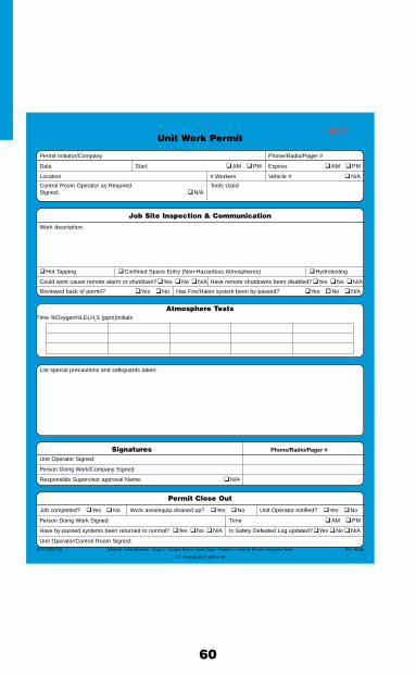
60
Unit Work Permit
Permit Initiator/Company Phone/Radio/Pager #
Date Start � AM � PM Expires � AM � PM
Location # Workers Vehicle # � N/A
Control Room Operator as Required Tools UsedSigned: � N/A
Job Site Inspection & Communication
Work description:
� Hot Tapping � Confi ned Space Entry (Non-Hazardous Atmospheres) � Hydrotesting
Could work cause remote alarm or shutdown? � Yes � No � N/A Have remote shutdowns been disabled? � Yes � No � N/A
Reviewed back of permit? � Yes � No Has Fire/Halon system been by-passed? � Yes � No � N/A
Atmosphere Tests Time %Oxygen %LEL H2S (ppm) Initials
List special precautions and safeguards taken:
Signatures Phone/Radio/Pager # Unit Operator Signed:
Person Doing Work/Company Signed:
Responsible Supervisor approval Name: � N/A
Permit Close Out
Job completed? � Yes � No Work area/equip.cleaned up? � Yes � No Unit Operator notifi ed? � Yes � No
Person Doing Work Signed: Time � AM � PM
Have by-passed systems been returned to normal? � Yes � No � N/A Is Safety Defeated Log updated? � Yes � No � N/A
Unit Operator/Control Room Signed:SFTY-002-779 Original - Unit Operator; Copy 2 - Control Room; Hard Copy - Posted or Held by Person Doing the Work Rev. 01/06
Q L Printing (907) 563-4743
0001

61
Unit Work Permit
Permit Initiator/Company Phone/Radio/Pager #
Date Start � AM � PM Expires � AM � PM
Location # Workers Vehicle # � N/A
Control Room Operator as Required Tools UsedSigned: � N/A
ControlRoomCopy
SFTY-002-779 Original - Unit Operator; Copy 2 - Control Room; Hard Copy - Posted or Held by Person Doing the Work Rev. 01/06
Q L Printing (907) 563-4743
0001

62
Any individual may invalidate this work permit at any time if they consider conditions or work methods to be unsafe.Anyone stopping work must: A. Inform the person doing the work;
B. Remove the site copy of the permit;C. Return it to the Unit Operator giving reasons for their actions.
Y N N/A General Items To Consider1. Spill prevention measures in place?2. Communications checked?3. Is equipment to be worked on correctly identified?4. Ladders/scaffold properly set?5. Proper PPE?6. Has job walk down been completed?7. Has face to face communication taken place?8. Is there a procedure and/or hazard assessment already
in place for this scope of work?
Y N N/A Hot Tap Procedure Items To Consider1. Hoses properly secured?2. Hot Tap machine pressure tested?3. Hot Tap package attached to this permit?4. First line supervisor notified?5. Safety notified?
Y N N/A Flammable & Combustible Fluid Transfer Items to Consider1. Wind direction for vapors?
2. Equipment spacing, positioning, electrical bonding?3. Emergency equipment access/fire extinguishers?4. Remote shutdown capability?5. “Supersucker”, 40 degrees below flashpoint?
6. Gas test considered?7. Person doing work understands North Slope Environmental Fluid Transfer Guidelines?
Non-Hazardous Confined SpaceY N N/A Items To Consider
1. Adequate ventilation?
2. Standby attendant present?
3. First line supervisor notified?
4. Safety notified?5. Sign In log required?
Y N N/A X-Ray Items To Consider1. Warning signs/lights/ropes?
2. Safe operating limits delineated?
3. UV’s by-passed if necessary?
4. Hot Work Permit required?
IF JOB SCOPE OR CONDITIONS CHANGE - STOP THE JOB - REEVALUATECLOSE OUT PERMIT WITH CONTROL ROOM WHEN WORK IS COMPLETE!
Critical Activity or Considerations (Check all that apply)
� Barricades/Signs � Ground Disturbance (ACWR) � Subsidence� Confined Space Entry/Work � H2S / Benzene � Use of New Chemical� Energy Isolation Complete � Ignition Sources � Use of Pipe Plug / Bladder� Emergency Reporting/Safe Area � Lifting Operations (Critical/Blind Lift) � Vehicle Ops (Height/Backing/Congestion)� Energized Electrical System >50v � Lifting/Rigging � Ventilation Adequate� Environmental Concerns � Multiple, Complex Job/SIMOPS � Walking/Working Surface� Ergonomics/Body Position � Nitrogen Use (N2) � Work Close to Halon Discharge Nozzles� Eye Wash/First Aid Location � Pinch Points/Line of Fire � Work on Safety Systems� Falling Objects � Severe Weather (Wind, Temperature, Etc.) � Working at Heights Unguarded
Checked boxes should be addressed on front of form under “Special Precautions and Safeguards Taken”Potential Energy Sources (ES*)
� Electrical (E) � Gravity (G) � Energy of Motion (M) � Biological (B)� Pressure (P) � Chemical (C) � Heat or Cold (H/C) � Radiation (R)
Eliminate - Control - ProtectReview additional hazards not on list along with safeguards taken
Area of Concern ES* Potential Hazards Actions to Eliminate, Control or Protect
63
Unit Work Standard
Purpose/ScopeThe Unit Work Standard ensures that the Person in Charge of any area or equipment is aware of all work done in their unit.
There are specific sign-in procedures for access to facilities as outlined in the General Safety Rules section of this Handbook. Verbal permission from operations, at a minimum, is required for access to all operating areas, with the exception of the Control Room. Routine access to facility pads will not require a Unit Work Permit.
All personnel shall also notify the Unit Operator or Control Room Operator when they are leaving the area and/or sign out.
The following work requires a Unit Work Permit:
• Constructionandnon-routinework;
• Hottapping(theportionofworkexclusiveofhotwork);
• Flammable and combustible fluid transfer when notattended full time by a Company Representative;
• Radiographyequipment(ifintrinsicallysafe)oroutsideaclassified area;
• Entry intoConfinedSpaceswithnon-hazardousatmo-spheres (examples of such Confined Spaces that could fall under the Unit Work Standard include vessel skirts, inlet air plenums, soffits, and process heaters after the fuel gas is blinded and all other potential energy sources are isolated).
The following is a list of examples of routine work that does not require a Unit Work Permit. This list is subject to periodic revision as activities are approved or deleted as required. People performing this routine work will still have to sign in for personnel accountability purposes in facilities or obtain verbal clearance via radio.
• Snow removal on normal roads and pads.
• Potable water delivery.
• Sewage pick-up.

64
• Fueling vehicles.
• Waste dumpster pick-ups.
• Delivery or pick-up of equipment (e.g. heaters) or materi-als.
• Checking running equipment (e.g., light plants).
• Security rovers.
• Visual inspections only either inside or outside various modules or skids.
• Monthly inspections (SCBA’s, vibration readings, etc.)
• Routine sampling by laboratory personnel.
• Other activities as identified and approved.
Well WorkPermission for access to a drillsite/wellpad must be obtained. Access to drillsite/wellpad is granted by contact with the Drill-site/Wellpad Operator.
Well isolation work that involves connecting or disconnecting a well from the flow lines requires a Process Opening/Blinding Permit (see Process Opening/Blinding Standard).
The following well work does not require a Unit Work Permit. Communication with the Drillsite/Wellpad Operator is manda-tory for the following activities.
• Well work operations including slick line, electric line, coiled tubing, work over, and drilling.
• Wellhead pumping activities including well and flow line freeze protection, flow line treatments, tubing displacements, mechanical integrity tests (MIT), acidizing, fracturing, hot oiling, setting and pulling of backpressure valves, etc.
• Well maintenance activities including valve greasing, wellhead problem diagnosis, gas lift troubleshooting, fluid level determinations, wellhead inspection, etc.
• Movement of equipment or vehicles on the wellpad during the above operations.

65
Objectives1. Ensure the area where the work to be done is inspected.
2. Provide communication with all departments concerned.
3. Document all hazardous conditions and special require-ments of the work area.
Permit InitiationPermits may be initiated by anyone and will be done at the appropriate control room or other designated location.
At the discretion of local management, FWRs or PMs may be used in lieu of completing a separate Unit Work Permit, pro-vided that all other provisions of the Unit Work Permit Standard are followed, (e.g., on-site communication, duration of permit, record keeping, etc.)
ResponsibilitiesUnit Operator/Issuing Authority:
1. Ensure the equipment and area have been properly pre-pared and are ready for the safe execution of work.
2. Ensure that lines to be demolished or removed are properly identified and marked.
3. Check placement and condition of safety equipment.
4. Make necessary tests for flammable and/or other hazard-ous conditions.
5. If hydro testing, see specific duties in the Hydrostatic Testing Standard.
6. List special precautions as necessary.
7. Show the Persons Doing Work the locations of the nearest communications equipment and applicable safety devices.
8. Review the questions and Task Hazard Assessment on the back of the Unit Work Permit.
9. Sign the Unit Work Permit after the above conditions have been met.

66
10. Ensure that the hard copy of the Unit Work Permit has been posted at the work location or with the Person Doing the Work if it cannot be posted at the job site.
11. Prevent an operation from being performed, which has the potential to cause the area or equipment to become unsafe while the permit is in effect. Consideration should be given to simultaneous operations.
12. Monitor the work as it progresses and perform gas checks as appropriate to ensure the conditions of the permit are not changing.
13. Advise relief operators of any permit in effect.
14. Notify Company Safety Representative for Hot Tap and Non-Hazardous Confined Space Entry.
15. Insure that emergency services are available.
16. Inspect the work site after any interruption has occurred prior to resuming work.
17. After the work is completed, inspect the work area and adjacent areas to determine that they are in a safe condi-tion and sign the permit close out section.
Control Room Operator or Drillsite/WellpadOperator:1. See specific duties under the Hot Tapping sections of this
Handbook (page 164).
2. Communicate to all personnel in the area if radiography (x-ray) is in progress.
3. Check with the Unit Operator prior to permit close out.
First-Line Supervisor:1. See specific duties under the Hot Tapping (page 164) and
Hydrostatic Testing (page 169) sections of this Handbook.
2. Determine and specify when the Standby Attendant and/or Entry Log are necessary when non-hazardous confined space entry work is to be performed.
67
Person Doing Work:1. Read, understand and follow the conditions listed on the
Unit Work Permit.
2. Post the hard copy of the Unit Work Permit at the work area or with the person doing the work if it cannot be posted at the job site.
3. Advise other workers of any special precautions or condi-tions pertaining to the job.
4. Survey the area to confirm safe working conditions. Know where the nearest telephone, fire alarm, emergency com-munications system, fire extinguisher, safety shower, first aid kit, etc., are before starting work, and know how to use them, if appropriate.
5. If hydro testing, see specific duties in the Hydrostatic Testing Standard.
6. If performing work in a confined space with a non-hazardous atmosphere, verify energy isolation as applicable, and post the hard copy of the permit at the entrance to the confined space.
7. Be constantly aware of conditions in the immediate work area, and be ready to stop work if conditions change. Do not resume work without approval of the Unit Operator.
8. Clean up and secure the work area after completion of work each shift. At the end of the shift or upon completion of the work, whichever comes first, notify the operator, return the permit to the Control Room or designated lo-cation, and sign the closeout portion on the permit copy of record. If the job is incomplete or the person or crew temporarily leaves the unit, the Person Doing Work must notify the Unit Operator.
Attendant: (For Confined Space Entry with Non-Hazardous Atmosphere)
Note: The Attendant requirement and/or Entry Log requirement may be waived by the First-Line Supervisor for situations where these extra precautions are not deemed necessary.
Note: Entry is defined as the breaking of the plane of the open-ing into the space by any part of the entrant’s body.
68
1. Read and understand the Unit Work Permit.
2. Remain outside the confined space entryway at all times during entry operations.
3. Properly use any non-entry rescue equipment provided and perform any other rescue and emergency duties without entering the confined space.
4. Be knowledgeable of and be able to recognize potential hazards.
5. Maintain an accurate log of all persons in the confined space.
6. Monitor activities inside and outside of the confined space to determine if it is safe for the persons making entry to remain in the space.
7. Maintain effective and continuous contact with persons inside the confined space and have a means of commu-nication with the Unit Operator.
8. The Attendant shall not enter a space until relieved by another qualified Attendant. Once relieved, they may become an entrant.
9. Summon rescue and other emergency services as soon as persons inside need assistance to escape from the confined space.
Special ConsiderationsPreparation for entry into a confined space with a non-hazardous atmosphere under the Unit Work Permit shall include energy isolation as appropriate in accordance with the Energy Isola-tion Standard.
Duration of Permits/Permit Close OutPermits will be in effect until job completion but will not extend beyond the end of the shift in which the permits were issued.

69
Hot Work Permit
Permit Initiator/Company Phone/Radio/Pager #
Date Start � AM � PM Expires � AM � PM
Location # Workers Vehicle # � N/A
Control Room Operator as Required, Tools UsedSigned: � N/A
Job Site Inspection & CommunicationWork Description:
Fire watch required? � Yes � No Fire extinguisher? � Yes � No Energy isolation complete? � Yes � No � N/A
Could work cause remote alarm or shutdown? � Yes � No � N/A Have remote shutdowns been disabled? � Yes � No � N/A
Reviewed back of permit? � Yes � No Has Fire/Halon system been by-passed? � Yes � No � N/A
Atmospheric Tests Time %Oxygen %LEL H2S (ppm) Initials
List special precautions and safeguards taken:
DO NOT ISSUE IF OPENING/BLINDING PERMIT IS IN EFFECT
Signatures Phone/Radio/Pager #
Unit Operator Signed:
Person Doing Work/Company Signed:
Responsible Supervisor approval Name: � N/A
Company Safety Representative Signed: � N/A
Permit Close Out
Job completed? � Yes � No Work area/equip.cleaned up? � Yes � No Unit Operator notifi ed? � Yes � No
Person Doing Work Signed: Time � AM � PM
Have by-passed systems been returned to normal? � Yes � No � N/A Is Safety Defeated Log updated? � Yes � No � N/A
Unit Operator/Control Room Signed:SFTY-002-778 Original - Unit Operator; Copy 2 - Control Room; Hard Copy - Posted or Held by Person Doing the Work Rev. 01/06
Q L Printing (907) 563-4743
0001

70
Hot Work Permit
Permit Initiator/Company Phone/Radio/Pager #
Date Start � AM � PM Expires � AM � PM
Location # Workers Vehicle # � N/A
Control Room Operator as Required, Tools UsedSigned: � N/A
Work Description: � Welding, Burning/Cutting, and Grinding in confi ned spaces or on process piping
ControlRoomCopy
SFTY-002-778 Original - Unit Operator; Copy 2 - Control Room; Hard Copy - Posted or Held by Person Doing the Work Rev. 01/06
Q L Printing (907) 563-4743
0001

71
Any individual may invalidate this work permit at any time if they consider conditions or work methods to be unsafe.Anyone stopping work must: A. Inform the person doing the work; B. Remove the site copy of the permit; C. Return it to the Unit Operator giving reasons for their actions.
Y N N/A General Items to Consider 1. Has Safety been notifi ed for welding in confi ned space or on process piping? 2. Fire Watch Required? 3. Fire extinguishers required? 4. Flammable materials removed? 5. Sumps/drains checked and covered? 6. Trash removed? 7. Are the welding leads and connnectors properly insulated and have no bare spots where arcing could occur? 8. Welding machines grounded at nearest point to the weld? If not, is there a continuous path to ground between the work and the machine? 9. Fire equipment inspected and ready to use and located at work site? 10. Fire blanket or catch basins needed for overhead hot work? 11. Are there any Opening/Blinding Permits in effect for the same Fire Zone? 12. Should Halon be isolated? 13. Communications checked? 14. Hot Tap Package complete and attached? a. Flow requirements met? b. Pressure requirements met? c. Engineering signed off on calculations? d. U.T. Report for the same line, and numbers correspond with those on line and elsewhere in Package? e. Welding procedure attached? f. Is the work being done on the right line? 15. Purging requirements met? 16. Considered relocating the wellhead shelter when welding on the structure? 17. Has job walk down been completed? 18. Has face to face communication taken place? 19. Is there a procedure and/or hazard assessment already in place for this scope of work?
IF JOB SCOPE OR CONDITIONS CHANGE - STOP THE JOB - REEVALUATECLOSE OUT PERMIT WITH CONTROL ROOM WHEN WORK IS COMPLETE!
Critical Activity or Considerations (Check all that apply)
� Barricades/Signs � Ground Disturbance (ACWR) � Subsidence � Confi ned Space Entry/Work � H2S / Benzene � Use of New Chemical � Energy Isolation Complete � Ignition Sources � Use of Pipe Plug / Bladder � Emergency Reporting/Safe Area � Lifting Operations (Critical/Blind Lift) � Vehicle Ops (Height/Backing/Congestion) � Energized Electrical System >50v � Lifting/Rigging � Ventilation Adequate � Environmental Concerns � Multiple, Complex Job/SIMOPS � Walking/Working Surface � Ergonomics/Body Position � Nitrogen Use (N2) � Work Close to Halon Discharge Nozzles � Eye Wash/First Aid Location � Pinch Points/Line of Fire � Work on Safety Systems � Falling Objects � Severe Weather (Wind, Temperature, Etc.) � Working at Heights Unguarded
Checked boxes should be addressed on front of form under “Special Precautions and Safeguards Taken”Potential Energy Sources (ES*)
� Electrical (E) � Gravity (G) � Energy of Motion (M) � Biological (B) � Pressure (P) � Chemical (C) � Heat or Cold (H/C) � Radiation (R)
Eliminate - Control - ProtectReview additional hazards not on list along with safeguards taken
Area of Concern ES* Potential Hazards Actions to Eliminate, Control or Protect
72
Hot Work StandardPurpose/ScopeThe Hot Work Standard minimizes the potential of fire or explo-sion in classified areas by requiring a Hot Work Permit. This applies but is not limited to:
1. Open flame, welding, burning/cutting, or grinding within 75 feet of a classified area;
2. The use of non-intrinsically safe electrical tools and instru-ments in a classified area;
3. Work on electrical circuits including the opening of explo-sion proof boxes or junction boxes in a classified area;
4. The use of spark producing devices in a classified area; Process line opening/blinding operations will require atmo-spheric testing while using pneumatic/hammer wrenches. A Hot Work Permit will not be required. Follow the require-ments of the Process Opening/Blinding Standard.
5. Hot work on portable and mobile containers which contain or have contained flammable or combustible materials;
6. Impedance thawing; and
7. Stress relieving of piping
A Hot Work Permit is required for mobile heaters, stationary trucks, cranes, and other mobile equipment operating within a classified area. A classified area extends 10 feet beyond the exterior wall or roof of a building, fan exhaust, vent, low point drain, high point vent, or flanges.
Vehicles in the following activities operating within 10 feet of a classified area shall require operator notification but not a permit:
• In transit,
• In snow removal,
• In routine well servicing by the drillsite operator,
• Delivery of parts and materials, and
• Manned well servicing operations such as coiled tubing units, slickline units, boom truck cranes, etc.
73
Hot work conducted in areas not addressed by this Standard (e.g. non-classified areas) may be performed under a Unit Work Permit. Applicable provisions of the Hot Work Standard shall apply as appropriate.
On drill rigs, all hot work inside the confines of the drill rig and associated buildings is the responsibility of the Rig Supervisor. Any hot work involving burning/cutting, welding, grinding, or the use of an open flame accomplished outside the rig and within 75 feet of a classified area requires a Hot Work Permit from the Drillsite/Wellpad Operator. All other hot work outside the rig and within 75 feet of a classified area requires notification of the drillsite/wellpad operator and a permit.
Any Hot Work Permits issued for operations or construction involving burning/cutting, welding, grinding, or the use of an open flame that are within 75 feet of a classified area of the rig, or down-wind from the rig on the same pad, shall require the verbal approval of the Rig Supervisor.
Objectives1. Ensure the work area is inspected and combustibles and
flammables are isolated for the hot work.
2. Establish fire watches when applicable.
3. Provide communication with all departments concerned.
4. Control how open flame or spark-producing equipment is used.
5. Formally document and communicate all hazardous conditions and special requirements of the work area.
6. Ensure local exhaust and/or general ventilation is adequate to keep the amount of toxic fumes, gases, or dust below maximum allowable concentrations or that appropriate respiratory protection is utilized.
74
Permit InitiationPermits may be initiated by anyone and will be done at the appropriate control room or other designated location.
ResponsibilitiesUnit Operator/Issuing Authority:
1. Do not issue a Hot Work Permit when an Opening/Blinding Permit is in effect in the same fire zone.
2. Inspect the work area and adjacent areas for a distance at least 35 feet around the hot work site, including the other side of any wall or barrier and on lower floor levels, to which sparks or heat might spread, this includes adjacent combustible walls, roofs, partitions and floors. Welding/cutting in proximity to ducts or systems that might carry sparks shall be shielded or shutdown if feasible.
3. Ensure the equipment and areas have been properly prepared and are ready for the safe performance of work.
4. Ensure that lines to be demolished or removed are properly identified and marked.
5. Ensure that all hollow spaces, cavities, or containers are tested and vented to permit the escape of air or gases prior to preheating, burning/cutting, or welding.
6. Make necessary tests for flammable and/or other hazard-ous conditions immediately prior to the start of hot work or when work is suspended for more than 2 hours. If the Operator is unable to safely get to the same location where the work is to take place (i.e. Rope Access Technology crew working at heights), the Operator may allow a trained work crew to perform gas tests under their direction.
7. Consider the need for continuous atmospheric monitoring.
8. Show the Persons Doing Work the locations of the nearest communications equipment and applicable safety devices.
9. Check placement and condition of proper fire extinguishers and other safety equipment.

75
10. Inform fire watch of potential fire hazards.
11. Review questions and Task Hazard Assessment on back of Hot Work Permit.
12. List special precautions as necessary.
13. Sign the permit after the above conditions have been met.
14. Ensure that the hard copy of the Hot Work Permit has been posted at the work location or with the Person Doing the Work if it cannot be posted at the job site.
15. Prevent an operation from being performed which has the potential to cause the area or equipment to become unsafe while the Hot Work Permit is in effect. For example, do not allow lab samples to be taken while hot work is taking place.
16. Monitor the work as it progresses to ensure that the condi-tions of the Hot Work Permit are not changing.
17. Stop the work if a change occurs which creates an unsafe condition. Work shall not resume until a safe condition is restored.
18. If conditions change, re-inspect and gas-check the work area and note readings on front of permit.
19. Advise relief operators of any permit in effect.
20. If any process upset or emergency alarm causes the shut-down of work, re-inspect the work area prior to allowing work to be resumed.
21. After work has been completed inspect the work areas and adjacent areas to determine that they are in a safe condition and sign the permit close out section.
Control Room Operator or Drillsite/Wellpad Operator:
1. Ensure that facility operation, construction, or maintenance will not be adversely affected by the proposed work activi-ties.

76
2. Notify the First-Line Supervisor (or designee) and receive their approval prior to starting hot work.
3. Sign the Hot Work Permit, certifying that the job is ready to proceed.
4. Check with the Unit Operator prior to permit close out.
First-Line Supervisor:1. Ensure all participants in the Hot Work Permit process
have fulfilled their duties and responsibilities.
2. Be satisfied that the proper precautions for hot work have been taken.
Person Doing the Work:1. Read, understand, sign, and follow the conditions listed on
the Hot Work Permit. Post the hard copy of the permit at the job site or with the Person Doing the Work if it cannot be posted at the job site.
2. Advise other workers of any special precautions or condi-tions pertaining to the job.
3. Survey the work area to confirm safe work conditions. Know the location of the nearest telephone, fire alarm, emergency communication system, fire extinguisher, safety shower, first aid kit, etc., before starting work, and know how to use them.
4. Confine all sparks and slag as close to the work area as possible.
5. Be constantly aware of conditions in the immediate work area and be ready to stop work, and notify the Unit Op-erator if conditions change. Do not resume work without approval of the Unit Operator.
6. Clean up and secure the work area after completion of work each shift. At the end of the shift or upon completion of the work, whichever comes first, notify the Unit Operator, return the permit to the Control Room or designated loca-tion, and sign the copy of record. If the job is incomplete and the person or crew temporarily leaves the unit, secure the work areas and notify the Unit Operator.

77
7. Strikers shall not be attached to clothing such as pant leg loops. Strikers shall be attached to the welding cylinders or carried in a toolbox or bag.
8. When an alarm or Emergency Announcement is made, stop all work, disconnect all electrical equipment, and turn off all gas cylinders. Do not resume any work until notified by the Unit Operator.
9. Persons working in close proximity to any welding or burning/cutting operation may not carry cigarette lighters, matches, or any other flame-producing device.
Fire Watch:Note: A dedicated fire watch is required for torch cutting, gas welding, arc welding and grinding, or as other conditions warrant.
1. Observe an area of at least 35 feet around the hot work site, including the other side of any wall or barrier and lower floor levels, and maintain the area free of combustibles and tripping hazards.
2. Have no other duties assigned while on watch.
3. Understand and follow the conditions listed on the Hot Work Permit.
4. Be trained in the use of fire extinguishing equipment provided.
5. Understand the alarms and where and how to activate them.
6. Notify the Person Doing the Work if any sparks are not contained at the work area.
7. Sound the alarm for assistance and extinguish any small fires started by sparks or slag.
8. Remain on the scene from the start until 30 minutes after the completion of all welding, burning/cutting, or grinding. Inspect the work area and adjacent areas to determine that they are in a safe condition prior to departure.
78
Company Safety Representative:Shall provide an independent assessment of the work area and sign the permit for any work involving:
• Welding, burning/cutting or grinding (excluding buffing) on any process piping that has not been depressurized, blinded and purged.
• Any burning/cutting, welding, open flame or grinding inside a confined space.
• Welding, burning/cutting, open flame or grinding on lines or equipment within the blinded boundaries of a confined space.
Heating equipment with an open flame does not require a Safety Representative to be present or sign the permit.
Special ConsiderationsWelding, burning/cutting, or grinding on equipment or pipelines which have not been depressurized, blinded and purged will require a written procedure from Engineering. This procedure shall include location, piping or equipment specifications, non-destructive examination, stress relieving information, and any other procedure that is deemed necessary to ensure the job can be performed safely. This procedure will be approved by the First-Line Supervisor and Project Engineer.
When welding on rotating equipment, be sure the ground strap is as close to the area being welded as possible.
Prior to welding, burning/cutting, or grinding on Vertical Sup-port Members (VSM) conduct an atmospheric test along the entire length of the VSM to ensure no flammable gases are present on the inside diameter of the pipe.
Blinding RequirementsHot work on depressurized, shut-in, or temporarily out-of-ser-vice process handling equipment, piping, and vessels requires a full-rated blind as close to the work as possible, however,

79
when blinding as close to the vessel/work as possible creates additional hazards or is impractical, blinds can be applied at another location with the approval of the Company First Line Supervisor and Company Safety Representative.
The approvals to apply the blind at another location will be documented on the Energy Isolation Procedure.
A double block and bleed does not meet the blinding require-ments for hot work. To allow a double block and bleed, a vari-ance is required.
By Government regulation, variances are not permitted for a double block and bleed in lieu of blinding for burning/cutting or welding on used drums, barrels, tanks, or other containers. Any pipelines or connections to the drum, tank, or vessel must be disconnected or blinded.
In cases of hot work on equipment which has been exclusively in seawater or potable water service, and there is no potential for hydrocarbon entry into the system, a single block, as a minimum, is acceptable for isolation in lieu of blinding.
All blinding shall be done in accordance with the Process Opening/Blinding Standard contained in this Handbook.
Neoprene Module InterconnectsNeoprene module interconnects (weather boots) are combus-tible. Additional precautions, such as covering with fireproof ma-terial, must be taken when burning/cutting, welding or grinding is to be done in close proximity to these module interconnects.
Hot Work in Confined SpacesWhen welding is to be suspended (unattended for a period of 30 minutes or more), all electrodes must be removed from the holders and carefully located so that accidental contact cannot occur, and the machine must be disconnected from the power source.
When gas welding or burning/cutting, the torch valves must be closed and the gas supply to the torch positively shut off at some point outside the confined area whenever the torch

80
is not being used for a substantial period of time (unattended for a period of 30 minutes or more). Where practicable, the torch and hose must also be removed from the confined space.
When welding or burning/cutting is being performed in a con-fined space, the gas cylinders and welding machines must be left outside of the confined space.
After welding operations are completed, the welder must mark the hot metal or provide some other means of warning other workers.
Local exhaust and/or general ventilation must be adequate to keep the amount of toxic fumes, gases, or dust below maximum allowable concentrations or appropriate respiratory protection must be utilized.
Duration of Permits/Permit Close OutPermits will be in effect until job completion but will not extend beyond the end of the shift in which the permits were issued.
VariancesAny deviation from this Standard requires written approval according to the Variance Standard.

81
Display Permit at Confi ned Space Entry Portal
Confi ned Space Entry PermitPermit Initiator/Company Phone/Pager/Radio Start � AM � PM
Location Vehicle # � N/A Expires � AM � PM
Tools Used Date
Purpose/Description of Work:
Pre-Entry Personal Protective Rescue & Emergency Preparation N/A No Yes Equipment N/A No Yes Preparation N/A No Yes
Depressurized Airline Unit w/Escape Cyl. Body HarnessPurged Airline Unit LifelineSteamed SCBA HoistCleaned Cartridge Respirator Rescue AirDrained - Full Face Fire Extinguisher/HoseBlinded - Half Face Rescue Response AvailableEnergy Isolated & Tagged Cartridge (specify) Communications Equipment N/A No Yes
Proper Ventilation RadioCool (<125°F) Air Temp. Chemical Goggles HornSign/Barricade Area Face Shield Phone Emergency NumberMSDS Available Disposable Coveralls Other Lighting (12 volt or GFCI) Rain GearLighting (Explosion Proof) Chemical SuitSafe Access/Egress Rubber BootsHot Work Permit Needed Protective Gloves (specify type) Atmospheric Test Equipment N/A No Yes
# Trained/Approved to UseOther Other Calibrated Cont. Monitoring Required Periodic Monit. Freq.:
List Precautions and Safeguards not identifi ed above:
Atmospheric Testing Acceptable Level ( ) ( ) ( ) Times ( ) ( ) ( )
• Percent Oxygen
• Lower Explosive Limit
• Hydrogen Sulfi de
• Benzene
• Carbon Monoxide
• NORM
• Other (specify)
Entry Supervisor Signature/Company: Individual Performing Periodic Atmospheric Testing/Company: / / � N/A
First Line Supervisor Signed: Company Safety Representative Signed:
Operator Signature: Job Completed: � Yes � N/A Worker Signed:
Return Hard Copy to Main Control Room & Notify Unit Operator Contractor Debriefed � Yes � N/ASFTY-002-780 Original - Unit Operator; Copy 2 - Control Room; Hard Copy - Person Doing the Work Rev. 01/06
Q L Printing (907) 563-4743
R
E
S
U
L
T
S
0001

82
Display Permit at Confi ned Space Entry Portal
Confi ned Space Entry PermitPermit Initiator/Company Phone/Pager/Radio Start � AM � PM
Location Vehicle # � N/A Expires � AM � PM
Tools Used Date
Purpose/Description of Work:
ControlRoomCopy
SFTY-002-780 Original - Unit Operator; Copy 2 - Control Room; Hard Copy - Person Doing the Work Rev. 01/06
Q L Printing (907) 563-4743
0001

83
Display Permit at Confi ned Space Entry Portal
Entry Supervisor/Company From: To:
From: To: Attendant/Company
Time
Entrant Company In Out In Out In Out

84
Confined Space Entry Standard
Purpose/ScopeThe purpose of this standard is to establish and maintain a safe environment for personnel entering a confined space that meets the following criteria:
1. Is large enough and configured so that an employee can bodily enter and perform the assigned work;
AND
2. Has limited or restricted means for entry and exit;
AND
3. Is not designed for continuous employee occupancy. Note: Entry into spaces meeting the criteria listed in items 1 through 3, but that do not meet any of the criteria listed in item 4, may be considered non-hazardous and may be executed utilizing the Unit Work Standard.
AND
4. If a confined space has one or more of the following characteristics, then it shall be considered a hazardous confined space and work shall be executed using the Confined Space Entry Standard (Permit).
• Contains or has the potential to contain a hazardous atmosphere;
• Contains material that has the potential for engulfing the entrant (i.e. sand, sludge, etc.);
• Has an internal configuration such that an entrant could be asphyxiated by inwardly converging walls or by a floor which slopes downward and tapers to a smaller cross-section; or
• Contains any other recognized serious safety or health hazard.
Examples of confined spaces that may meet the criteria iden-tified above include, but are not limited to, process vessels, process towers, tanks, sumps, pits, sewers, compartments with manhole, valve pits, well cellars, pipelines, and excavations more than 4 feet deep.

85
Note: Entry is defined as the breaking of the plane of the open-ing into the space by any part of the entrant’s body.
Examples of spaces that could fall under the Unit Work Standard include vessel skirts, inlet air plenums, soffits, and process heaters after the fuel gas is blinded and all other potential energy sources are isolated.
For purposes of this Standard, a hazardous atmosphere is one which may expose employees to the risk of death, inca-pacitation, impairment of ability to self-rescue (i.e. to escape unaided from the workspace), injury, or acute illness from one or more of the following:
• Flammable gas, vapor, or mist in excess of 10% of the lower explosive limit (LEL).
• Atmospheric oxygen concentration below 19.5% or above 23.5%.
• Atmospheric concentration of a toxic or hazardous substance which could result in a dose in excess of the Permissible Exposure Limit (PEL) for the substance and which could subsequently cause death, incapacitation, impairment of self-rescue capability, injury, or acute illness.
• Any other atmospheric condition that is immediately dan-gerous to life or health, i.e. poses an immediate or delayed threat to life or that would cause irreversible adverse health effect or that would interfere with an individual’s ability to escape unaided from the space.
Objectives1. Properly identify hazards
2. Institute appropriate controls, safeguards, and actions to protect personnel.
3. Coordinate all necessary permits and procedures includ-ing hot work and/or energy isolation.
Permit InitiationPermits may be initiated by anyone and will be done at the appropriate Control Room or other designated location.

86
Contractor RequirementsContractors who will conduct entries into confined spaces as defined in this Standard shall be informed of the elements included in the Confined Space Entry Standard, the hazards identified with respect to the space, any precautions or pro-cedures that have been implemented for the protection of employees in or near the confined space, and the procedures that will be utilized to coordinate the entry operations between various contractors and Company personnel.
The contractor shall be debriefed at the time of closeout of the permit regarding any new hazards confronted or created during the entry.
Confined space entries that are not conducted within Company structures such as flow stations, gathering centers, processing centers, drillsite/pad manifold buildings, gas plants, etc., may be executed using the Contractor’s Confined Space Entry Program, provided that:
• Company personnel will not be entering the confined space,
• A written concurrence between the contractor, the Com-pany Supervisor responsible for getting the work done, and the Company Supervisor responsible for the area, is signed prior to the start of the job, and
• The Contractor’s Confined Space Program meets or ex-ceeds the requirements set forth by 29 CFR 1910.146. (This certification must be included in the written concur-rence document.)
General Considerations1. The confined space permit does not always authorize
work to begin. It may need to be accompanied by an ap-propriate Unit or Hot Work Permit.
2. When personnel entry into a Confined Space is required, job specific procedures shall be followed. The procedure will outline the draining, blinding, cleaning, inspection and work to be performed. The detail of the procedure will be

87
appropriate to the job. This procedure should be reviewed by all involved departments, including Safety, before work begins.
3. Prior to entry, the contents and hazards of the Confined Space shall be identified. Whenever possible, tanks, ves-sels and piping shall be cleaned by water washing, flushing or steaming. Cleaning by hand should be limited to final cleanup unless no other cleaning process is feasible.
4. Prior to entry, all potential sources of energy affecting the space shall be isolated in accordance with the Energy Isolation and Opening and Blinding Standards. When lines are not disconnected and misaligned, full rated blinds shall be installed. Double block and bleeds are not permitted for entry operations. Furthermore, vapor barriers are not an acceptable substitute for blinds.
5. All connecting lines to the vessel shall be physically dis-connected and misaligned or blinded. Blinding should be as close to the vessel/work as possible, however, when blinding as close to the vessel/work as possible creates additional hazards or is impractical, blinds can be applied at another location with the approval of the Company First Line Supervisor and Company Safety Representative. This shall be done following the Opening and Blinding Standard. The approvals to apply the blind at another location will be documented on the Energy Isolation Procedure.
6. After a confined space has been depressurized, cleaned, isolated, and flushed as applicable it shall be tested prior to the complete removal of any hatch, man-way, etc. A confined space is safe to open (not enter) if the con-centration of flammable vapors is less than 50% of the lower explosive limit and provisions are made to vent the remaining vapor or gas to an appropriate location outside the skid or work location.
7. After a space has been opened, a “Do Not Enter” sign or tag shall be placed over all potential entry points indicating that the space is not safe for entry. This sign or tag shall remain there until a Confined Space Entry Permit has been issued and a “Safe to Enter Sign” has been posted.
88
8. Adequate ventilation shall be maintained in the confined space throughout the entry operation. All ventilation equipment shall be bonded and grounded. If mechanical ventilation is used it must be located in such a manner that it will not introduce contaminants such as gas or toxic vapors. In addition, it should be placed in such a manner that it will not prevent egress from the space. This will be verified by the Safety Department personnel and monitored by the Standby Attendant.
9. An area immediately outside the confined space shall be made available for decontamination as necessary.
10. Retrieval systems shall be used whenever an entrant enters a confined space as covered by this section unless the retrieval system would increase the overall risk of the entry or would not contribute to the rescue of the entrant. Safety Department personnel will determine when retrieval systems are appropriate.
11. When retrieval systems are utilized, the following shall be performed:
• A pre-plan shall be developed with Emergency Ser-vices.
• Attendants will be trained on the retrieval system. • Retrieval systems will be inspected prior to entry.
12. Any hot work in a location that may affect the confined space shall be approved by all parties who have autho-rized and signed the Confined Space Entry Permit. Any hot work performed within the boundaries of a confined space shall be approved and signed off by the Safety Department and should be referenced to the Hot Work Standard under the “Hot Work in a Confined Space” sec-tion. A test of the atmosphere where the hot work is to take place shall be performed by the Safety Department and documented on the Hot Work Permit.
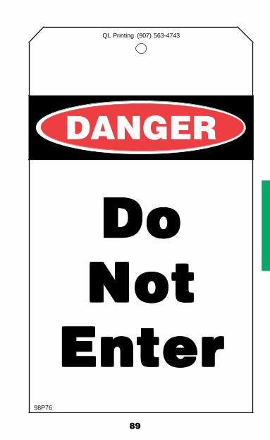
89
DANGER
QL Printing (907) 563-4743
DoDoDoDoDoNotNotNotNotNot
EnterEnterEnterEnterEnter98P76

90
QL Printing (907) 563-4743
SafeTo Enter
Restrictions
(See Permit)98P77

91
ResponsibilitiesUnit Operator/Issuing Authority:
1. Ensure that all blinds are installed in accordance with the Opening and Blinding Standard.
2. Ensure all pneumatic, hydraulic, thermal, electrical, and mechanical energy sources have been isolated in ac-cordance with the Energy Isolation Standard.
3. Depressure drain and purge all enclosures and process lines. Open all drain lines, gauge glasses, level control transmitters, bridles and similar equipment attached to the enclosure while purging, washing and cleaning the equipment. If the device cannot be cleaned, it shall be isolated from the enclosure.
4. Ensure appropriate “Do Not Enter” or “Safe To Enter with Restrictions” signs or tags are posted at all possible entry points.
5. Endorse all permits affecting the Confined Space Entry Permit.
6. Prevent an operation from being performed, which has the potential to cause the area or equipment to become unsafe while the permit is in effect.
7. Monitor the work as it progresses to ensure that the condi-tions of the permit are not changing.
8. Communicate hazards to the Entry Supervisor and ensure that all personnel working under the permit are aware of the hazards present.
9. Ensure there is a proper handover to the oncoming Unit Operator during shift change. Note: Renewal of the permit is required every shift.
10. Ensure tests for oxygen concentration, flammability, and other hazards, in that order, have been conducted prior to entry.
11. Ensure adequate ventilation has been established.
92
12. After the safety inspection is completed and before entry is made by authorized entrants list any other precautions and sign the permit.
13. Stop the work if a change occurs which creates an unsafe condition. Work shall not resume until a safe condition is restored and the Confined Space Entry Permit is revali-dated per the General Permitting Rules.
Control Room Operator or Drillsite/Wellpad Operator:1. Ensure that the facility operations, construction, and
maintenance activities will not be adversely affected by the proposed work activities.
2. Notify the First-Line Supervisor (or designee) and receive their approval prior to entry.
3. Hold copies of the permits until the work is ready to start.
4. Debrief the contractor at the time the permit is closed out to ascertain whether any new hazards were confronted or created.
5. Check the box on the permit accordingly and, if new hazards were confronted or created, either note them on the hard copy being filed or attach a description of the hazards to the permit for filing.
6. Notify the Unit Operator when the permit is closed out.
First-Line Supervisor:1. Ensure the space is safe to enter, e.g., safeout procedures
are complete and up to date and the Energy Isolation Standard has been followed.
2. Ensure that the Authorized Entrant, Attendant(s), and Entry Supervisor have received the required training and can perform their assigned duties.
3. Sign the permit after the safety inspection is completed and before entry is made by authorized entrants.
4. Verify the confined space entry work is complete and ready to close. This includes ensuring that all personnel have exited the space and all equipment has been removed.

93
Entry Supervisor:A determination shall be made during the pre-job planning phase of the Confined Space Entry as to who will serve as the designated Entry Supervisor. Logical choices depending upon the complexity of the job, anticipated duration, number of entrants, etc., would include the Maintenance Supervisor, Project Engineer, Facility Supervisor, Lead or Unit Operator, Lead Maintenance Technician, or Contract Work Leader.
1. Inform the Authorized Entrants of the hazards identified with respect to inside or outside the space, any precau-tions or procedures that have been implemented for the employees in or near the confined space, and procedures that will be utilized to coordinate entry operations between companies.
2. Know the hazards that may be faced during entry, includ-ing the mode, signs or symptoms of exposure. Remain informed of hazards that may be present due to other work being performed in the vicinity of the confined space.
3. Verify that rescue services are available and that the means for summoning them are operable.
4. Verify by checking that the appropriate entries have been made on the permit, that all tests specified by the permit have been conducted, and that all procedures and equip-ment specified by the permit are in place before endorsing the permit and allowing entry to begin.
5. Remove unauthorized individuals who enter or who at-tempt to enter the confined space.
6. Whenever responsibility for confined space is transferred, and at intervals dictated by the hazards and operations conducted in the space, determine that entry operations remain consistent with the terms of the entry permit and that acceptable entry conditions are maintained.
7. Terminate entry and cancel the permit when the operations covered by the permit are completed or when a condition that is not allowed under the entry permit arises in or near the space.

94
8. Suspend all operations and evacuate confined space any time the Rescue Team becomes unavailable. This includes when Phase III weather conditions are in effect. The work cannot resume until the Rescue Team returns to stand-by mode.
9. Ensure that employees working as part of the confined space entry crew have been trained in their individual job responsibilities as well as the hazards associated with the confined space entry work.
10. The Entry Supervisor shall be readily available to the confined space entry location.
11. Monitor the work as it progresses to ensure that the condi-tions of the permit are not changing.
12. At the end of the shift or upon completion of the work, whichever comes first, return the permit to the Control Room or designated location, sign the “copy of record,” and be debriefed.
Authorized Entrant:1. Verify energy isolation as applicable.
2. Read and understand the Confined Space Entry Permit and check with the Unit Operator before initial entry of the Confined Space. Log in and notify the Attendant upon each entrance and exit of the confined space.
3. Know the hazards that may be faced during entry including the mode, signs or symptoms of exposure.
4. Properly utilize the equipment provided for testing or moni-toring, ventilation, communications, lighting, barricading, access, and personal protective equipment.
5. Check all safety equipment prior to entry, e.g. respirators, airlines, PPE etc.
6. Communicate with the Attendant as necessary to enable the Attendant to alert Authorized Entrants of the need to evacuate the space.

95
7. Alert the Attendant whenever Authorized Entrant rec-ognizes any warning sign or symptom of exposure to a dangerous situation or the Authorized Entrant detects a prohibited condition.
8. Exit from the confined space as quickly as possible whenever an order to evacuate is given, a warning sign or symptom of exposure is recognized, a prohibited condition is detected, or an evacuation alarm is activated.
9. Clean up and secure the work area after completion of work each shift. If the job is incomplete and the person or crew temporarily leaves the unit, the Authorized Entrant must notify the Unit Operator.
10. Stop all work when an alarm or Emergency Announcement is made and exit the confined space. Do not resume any work until notified by the Unit Operator.
Attendant:1. Perform no other duties that might interfere with the Atten-
dant’s primary duty to monitor and protect the authorized entrants.
2. Read and understand the Confined Space Entry Permit.
3. Remain outside the confined space main entryway at all times during the entry operations.
4. The Attendant shall not enter a space until they are relieved by another qualified Attendant. Once relieved, they may become an entrant.
5. Continuously maintain an accurate log of all persons in the confined space.
6. Warn unauthorized persons away from the space. Advise unauthorized persons that they must exit immediately if they have entered the space, and advise the Entry Supervisor and the authorized entrants if unauthorized persons have entered the authorized space.
96
7. Be knowledgeable of and be able to recognize potential hazards that may be faced during the entry including the mode, signs or symptoms of exposure. Be aware of the potential behavioral effects of hazard exposure of entrants.
8. Post hard copies of permits related to the confined space entry at the main entry of the confined space. All entrances deemed safe shall have an Attendant.
9. Ensure that all authorized entrants are in compliance with the requirements stated on the Confined Space Entry Permit.
10. Monitor activities inside and outside the confined space to determine if it is safe for the persons making entry to remain in the space.
11. Maintain effective and continuous contact with persons inside the confined space, and have a means of com-munication with the Unit Operator.
12. Order persons to immediately evacuate the confined space when a prohibited condition is detected, behavioral effects of hazardous exposure are detected, a situation outside the confined space is detected that could endanger entrants, or if the Attendant cannot safely and effectively perform all of the required duties.
13. Summon rescue and other emergency services as soon as persons inside need assistance to escape from the confined space.
Company Safety Personnel:1. Verify that the space has been properly prepared.
2. Test for oxygen content, flammability, toxic materials and/or other hazards prior to entry.
3. Make the first entry into the enclosure, if necessary, to complete the safety inspection.
4. Coordinate any special precautions and sign the Confined Space Entry Permit.

97
5. Endorse all Hot Work Permits that might affect the Confined Space Entry Permit.
6. Decide what restrictions will be imposed on the permit.
7. Ensure the appropriate Company procedures are followed and documented when re-classifying a confined space.
8. Determine whether or not a retrieval system or other emergency response equipment is required at the job site.
9. Ensure that emergency services are available.
Atmospheric MonitoringThe space being entered must be tested for oxygen content, flammable gas, toxic gasses and other potential contaminants. During the tests all forms of forced air ventilation must be shut down. The following test sequence will be followed while performing atmospheric monitoring.
Test Sequence
Oxygen ContentEntry into a space with less than 19.5% oxygen will require a SCBA or airline respirator with an escape bottle. Entry into a space with an atmosphere containing more than 23.5% oxygen is not allowed.
Flammable GasNo entry will be made into any space where the atmosphere contains more than 10% of the lower explosive limit (LEL). Flammable gas samples should be taken from points within the space remote from openings. Where there are liquids or sludge present the samples should be taken within 6 inches of the surface as well as at the top of the space and interme-diate points.
H2SEntrance into spaces where the concentration of H2S is greater than 10 ppm shall be in accordance with the H2S Standard.
98
Other Toxic ContaminantsOther potential contaminants must be tested for as deemed appropriate by the nature of the Confined Space and the anticipated hazards. These can include, but are not limited to pH, NORM, toxic gases (such as Benzene, CO), other toxic substances etc.
Periodic monitoring shall take place every 12 hours at a mini-mum. More frequent testing may be required as indicated on the Confined Space Entry Permit.
Duration of Permits/Permit Close Out1. Permits will be in effect until the job is completed but will
not extend past the end of the shift during which they were issued.
2. If a change in any of the conditions listed on the permit results in an unacceptable condition, work must cease and the permit becomes invalid. Prior to the re-initiation of work activities the Confined Space Entry Permit must be revalidated by the Entry Supervisor and the Unit Operator.
3. If at any time during the permit, rescue or emergency ser-vices become unavailable, all work in the confined space shall be suspended and all occupants shall evacuate the confined space. After Emergency Services become avail-able, work may continue as long as the Confined Space conditions have not changed, and the space is re-evaluated prior to resuming work by the Entry Supervisor and Unit Operator.
4. If a confined space is to be reclassified from a hazardous confined space to a non-hazardous confined space, the permit will be closed out and a new Unit Work Permit issued.
VariancesAny deviation from this policy requires a written approval as outlined in the established Variance Standard.

99
MA
ST
ER
CA
RD
En
erg
y Is
ola
tio
n L
ist
M
aste
r C
ard
#
Faci
lity:
M
odul
e/S
kid
Dat
e /
Wor
k D
escr
iptio
n
Des
igna
ted
Ope
rato
r
Rea
son:
�
Ene
rgy
Isol
atio
n Ty
pe: �
Loc
kbox
�
Haz
ard
� D
ecom
mis
sion
ed
Isol
atio
n ve
ri� e
d b
y at
tem
ptin
g to
sta
rt fr
om e
very
loca
tion?
� Ye
s �
No
D
EV
ICE
B
LIN
D
CA
R S
EA
L C
AR
SE
AL
LO
CK
OU
T
MO
DU
LE/
(BLI
ND
, VA
LVE
, S
IZE
&
LOC
ATIO
N A
ND
SE
RV
ICE
IN
STA
LLE
D:
RE
MA
RK
S
RE
MO
VE
D:
BR
OK
EN
R
EP
LAC
ED
TA
G N
O.
SK
ID N
O.
BR
EA
KE
R)
RAT
ING
DAT
E/IN
ITIA
L
DAT
E/IN
ITIA
L Y
OR
N
Y O
R N
Ad
dit
ion
al In
form
atio
n In
sid
e?
Ye
s
No
SF
TY-
002-
781
Rev
. 01/
06
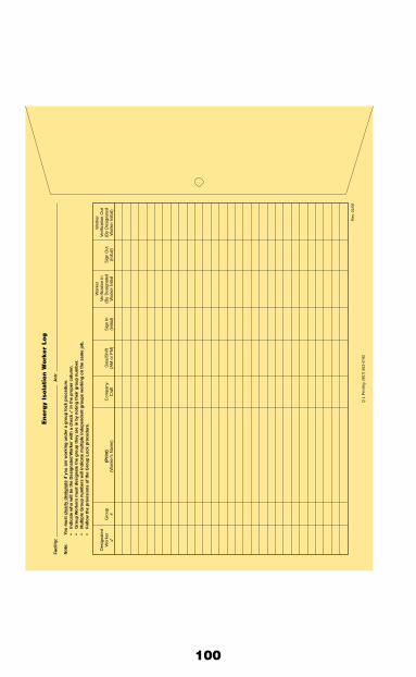
100
Energ
y Is
ola
tion W
ork
er
Log
Faci
lity:
Job
:
No
te:
You
mu
st c
lear
ly d
esig
nat
e if
yo
u a
re w
ork
ing
un
der
a g
rou
p lo
ck p
roce
du
re.
•In
dic
ate
wh
o w
ill b
e th
e D
esig
nat
ed W
ork
er w
ith
a c
hec
k �
in t
he
pro
per
co
lum
n.
•G
rou
p W
ork
ers
mu
st d
esig
nat
e th
e g
rou
p t
hey
are
in b
y n
oti
ng
th
eir
gro
up
nu
mb
er.
•M
ult
iple
Gro
up
nu
mb
ers
will
ind
icat
e m
ult
iple
ind
epen
den
t g
rou
ps
wo
rkin
g o
n t
he
sam
e jo
b.
•F
ollo
w t
he
pro
visi
on
s o
f th
e G
rou
p L
ock
pro
ced
ure
.
Wor
ker
Wor
ker
Des
igna
ted
Verif
icat
ion
InVe
rific
atio
n O
utW
orke
rG
roup
(Pri
nt)
Com
pany
Dat
e/S
hift
Sig
n In
(By
Des
igna
ted
Sig
n O
ut(B
y D
esig
nate
d�
#(W
orke
r’s N
ame)
Cra
ft(A
M o
r P
M)
(initi
al)
Wor
ker
Initi
al(in
itial
)W
orke
r In
itial
)
Rev
. 01/
06
Q L
Prin
ting
(907
) 56
3-47
43
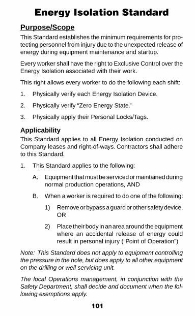
101
Energy Isolation StandardPurpose/ScopeThis Standard establishes the minimum requirements for pro-tecting personnel from injury due to the unexpected release of energy during equipment maintenance and startup.
Every worker shall have the right to Exclusive Control over the Energy Isolation associated with their work.
This right allows every worker to do the following each shift:
1. Physically verify each Energy Isolation Device.
2. Physically verify “Zero Energy State.”
3. Physically apply their Personal Locks/Tags.
ApplicabilityThis Standard applies to all Energy Isolation conducted on Company leases and right-of-ways. Contractors shall adhere to this Standard.
1. This Standard applies to the following:
A. Equipment that must be serviced or maintained during normal production operations, AND
B. When a worker is required to do one of the following:
1) Remove or bypass a guard or other safety device, OR
2) Place their body in an area around the equipment where an accidental release of energy could result in personal injury (“Point of Operation”)
Note: This Standard does not apply to equipment controlling the pressure in the hole, but does apply to all other equipment on the drilling or well servicing unit.
The local Operations management, in conjunction with the Safety Department, shall decide and document when the fol-lowing exemptions apply.
102
2. This Standard DOES NOT apply to the following:
A. Minor tool changes/adjustments and other minor services activities that meet all 3 of the following criteria.
1) It is essential that the equipment continue to operate, AND
2) The work is routine, repetitive, and part of the normal operation, AND
3) Alternate protection methods, other than energy isolation, are used. Examples: machine guards, electrical “hot sticks,” a local control switch under the Exclusive Control of the worker.
B. Work on corded or plugged equipment, PROVIDED:
1) Unplugging the equipment results in complete iso-lation of the equipment from all energy sources, AND
2) The plug is under the Exclusive Control of the worker
C. Hot Tap Operations PROVIDED:
1) It is essential that the equipment continue to operate, AND
2) Shutdown of the equipment is impractical, AND
3) Documented procedures are used which include specifically designed equipment to provide prov-en, effective personnel protection (Example: An Engineering package using the hot tap machine.)
D. Electrical work performed by technicians on power generation and transmission and distribution systems. This is an exception to the Facility Electrical Lockout and Tagout for plant equipment as stated in this section and shall fall under power generation, transmission and distribution as regulated by CFR 1910.269. This electrical energy isolation shall use utility switching orders.
103
Locks and TagsAll individually assigned Personal Locks and Tags shall be removed ONLY by the person who installed them. All lock out devices used for energy isolation are not to be used for any other purpose.
This Standard recognizes the following locks and tags:
1. Personal Lock - A lock, or set of locks, with a single, unique key. These locks shall meet the following requirements:
A. Be used exclusively for energy isolation and not for any other purpose.
B. Be standardized, colored red and clearly labeled or tagged with the employee’s name and contact number.
C. Personal Locks shall be issued to an individual em-ployee and the key shall be under the control of that individual.
2. Device Lock – Uniquely Keyed lock(s) where the key is under the exclusive control of the lockbox. This lock is applied directly to the energy isolation device when a lockbox Lockout technique is being used. Device Locks that are assigned for use with a lockbox shall have an “EI” tag attached.
3. Control Lock - These are keyed-alike locks that are used to protect the process or equipment, and are not to be used for personal protection. Control Locks are generally the first lock on a lockbox and the last lock off.
A. Control Locks for Operations - Color-coded Orange.
1) These locks are used by Operations personnel and commonly referred to as “Operations Locks” or “Operators’ Locks.”
2) If an operator will be a worker, the Operator must apply a Personal Lock to the lockbox and fill out all associated forms.
B. Control Locks for Electrical – Color-coded Yellow. C. Control Lock for Mechanical – Color-coded Brown. D. Control Lock for Instrumentation – Color-coded Green. E. Control Lock for Projects/Contractors/Vendors – Color-
coded White with Company name.

104
4. “Energy Isolation (EI)” Tag – A tag used to identify hazards that could present a threat of death or serious injury to personnel. These tags shall be attached to all energy isolation devices. These tags shall meet the following requirements (see Tagging and Flagging Standard):
A. Be standardized with the same style, label, print, and format.
B. Be able to withstand the environmental conditions where it is applied and still be legible.
C. Be attached with a non-reusable, self-locking device, such as a nylon cable tie, that is able to withstand a minimum 50 lb. force without breaking.
D. Be designed with a removable tag stub.
E. Be stamped with a unique number both on the tag and on the tag stub.
F. Be clearly and completely filled out with employee’s name/position and contact number.
5. Lockout is always required over tagout; therefore:
A. All Energy Isolation Devices that are lockable MUST be locked and tagged.
B. If an energy isolation device CANNOT be locked, then an “EI” tag shall be attached at the same location as a lock would have been installed. Alternative safety measures to provide full employee protection shall be undertaken, such as the removal of an isolating circuit element, blocking of a controlling switch, opening of an extra disconnecting device, or the removal of a valve handle to reduce the likelihood of inadvertent energization.
6. If an energy isolation device is being used for more than one energy isolation, then the device shall have separate locks and tags for each energy isolation.
105
7. If the worker who installed a Personal Lock or tag is not available to remove it, or when a worker who signed in on the job and then fails to sign out is not available, then the following procedure shall be followed by the worker’s First-Line Supervisor:
A. Verify that the worker is not in the work area.
B. Ensure the safety and integrity of the equipment to be re-energized before removing the lock or tag.
C. Authorize the physical removal of the Personal Lock (or the signing out on the worker Log) by signing the worker Log next to the worker’s name.
D. Make all reasonable efforts to contact the worker to inform them that their Personal Lock has been removed or that they failed to sign out.
E. Ensure that the worker is informed that his/her Per-sonal Lock has been removed BEFORE the worker returns to the work area.
Lockout TechniquesNote: For the purpose of this Standard, the term “Operator” shall be used to describe the Authorized Employee in charge of the Energy Isolation. In facilities other than process facilities, this could mean a maintenance employee or contract employee.
Lockbox Technique1. The Operator locks all lockable energy isolation devices
with a Device Lock. This Device Lock is the first one on an energy isolation device, the last one off and the last item signed off the energy isolation list.
2. The Operator tags all energy devices, including both lock-able and non-lockable devices, with a “EI” Tag.
3. The Operator places inside the lockbox:
A. The unique key(s) for the Device Lock(s) that are attached to the energy isolation devices.
B. If tags are used in lieu of locks because the device will not accept a lock, then the stubs are placed in the lockbox or Master Card envelope.

106
4. The Operator “Locks” the lockbox at the hasp with their Control Lock.
5. All workers or the Designated worker attach their Personal Locks on the lockbox at the beginning of the shift, remove them at the end of the shift, and sign in and out of the worker Log. If a worker is not working under a Designated worker’s lock, then the worker will attach their Personal Lock to the lockbox.
6. When the work is completed, all workers or the Designated worker remove(s) their Personal Locks from the lockbox, and then the Operator “unlocks” the lockbox and uses the unique key(s) and tag stubs to remove all the Device Locks from the energy isolation devices.
Lockout Tagout TechniqueThe Lockout Tagout Technique can be used without a written procedure for situations where the following conditions are met:
1. The work is completed within the worker’s shift.
2. The machine or equipment has no potential for stored or residual energy or re-accumulation of stored energy after shut down which could endanger employees.
3. The machine or equipment has a single energy source which can be readily identified and isolated.
4. The isolation and locking out of that energy source will completely de-energize and deactivate the machine or equipment.
5. The machine or equipment is isolated from that energy source and locked out during servicing or maintenance.
6. A single lockout device will achieve a lockout condition.
7. The lockout device is under the Exclusive Control of the Authorized Employee performing the servicing or main-tenance.
107
8. The servicing or maintenance does not create hazards for other employees.
9. The employer, in utilizing this exception, has had no acci-dents involving the unexpected activation or re-energization of the machine or equipment during servicing or mainte-nance.
10. Operations can apply a Control Lock to protect equipment/process if they choose to do so.
NOTE: In the above cases, the worker shall attach their indi-vidually assigned Personal Lock and tag directly on the energy isolation device. Example: Motor PMs.
Energy Isolation Procedures1. Written Energy Isolation/Safeout Procedures are required
for all energy isolations involving more than one energy isolation device. It is recommended that P&ID’s or the appropriate engineering documentation be utilized when developing energy isolation/safe out procedures.
2. These energy isolation procedures shall be specific to each piece of equipment being serviced or maintained.
3. Specific procedures shall include procedural steps unique to the equipment being isolated, such as:
A. Shutting down the equipment B. Isolating the equipment C. Locking out the equipment D. Releasing any stored energy in the equipment E. Verifying “Zero Energy State” F. Returning the equipment back to service
4. Except for Temporary Re-energize Procedures listed in this Standard, for any energy isolation device that must be installed/removed more than once (for example, re-opening valves used for blinding operations, then re-isolating the valves in order to remove the blinds);
• Separate sign on/sign off entries must be made on the energy isolation list (EIL), OR
• Separate energy isolation procedures (EIP)/EIL’s must be used.
108
5. Energy isolation procedures or changes to energy isolation procedures shall be approved by First-Line Supervision or Designee.
6. Temporary Re-energize Procedures (if applicable).
A. These procedures are required if a part of the energy-isolated equipment must be re-energized to ensure proper servicing or maintenance.
B. These procedures shall include the following:
1) Notification of all affected employees that part of the equipment is being temporarily removed from energy isolation.
2) Removal of all tools and materials.
3) Removal of any Personal Locks and “EI” tags.
4) Energizing of the equipment.
5) De-energizing the equipment once proper servic-ing or maintenance is completed.
6) Reapplication of the Energy Isolation/Safe Out Procedure.
7) Notification of all affected employees that the equipment is being returned to energy isolation.
7. Documents Used
A. Energy Isolation List (EIL; either on Master Card or separate sheet)
B. Worker Log (either on Master Card or separate sheet)
C. Energy Isolation/Safe Out Procedures as required.
All documents must be completely filled out.
Energy Isolation Methods
The following Isolation Methods for Electrical and Pressure shall be considered, in the order given.

109
Electrical Energy Sources1. On electrical equipment or circuits with the potential of
50 volts or higher, the electrical supply will be turned off and locked out in accordance with the following:
A. A qualified/authorized employee (normally the unit operator) will turn off the power to the equipment that’s being worked on by opening the circuit breaker. The equipment shall be tested to insure that it is de-energized by trying the start/stop switch.
B. If the equipment cannot be tested by the use of a start/stop switch or if the work involves electrical components of the equipment (such as motor leads), then a qualified electrician will be required to test the load side of the circuit breaker to insure that the equipment is de-energized.
C. Once the equipment has been tested and found to be de-energized, the qualified/authorized employee shall lock and tag the equipment per the energy isolation standard and complete the energy isolation list.
D. Electrical equipment rated above 480 volts shall be isolated by a qualified and authorized person or a qualified electrician during safe outs.
2. When the tagout option is used for electrical isolation such as a circuit breaker that cannot be locked out, the qualified electrician shall isolate the energy source by:
A. Removal of an isolating circuit element, or
B. Racking out a breaker.
3. The following Wiring Disconnect Procedure may be used when it is not possible to physically lock out an electrical isolating device:
A. The electrician disconnecting the power source will test the circuit to assure that it is de-energized. The wires will be disconnected, properly isolated and tagged so that they do not constitute a hazard.
B. The electrician shall tag the disconnect switch with a “EI” tag and log it into the Energy Isolation List.
110
C. The Operator and worker(s) shall attach a tag on the outside of the MCC cubicle or disconnect switch just as they would install a lock if the switch were locked out.
D. Under no circumstances will the wiring be reconnected if there is another person’s tag in place. Each person must remove their own tag just as they would remove their own lock, as specified under control of locks/tags and keys.
Note: Treat all disconnected neutral conductors, ground con-ductors, and bonding jumpers as energized.
Pushbuttons, selector switches, and other control circuit type devices that do not directly control the electricity shall not be used as energy isolation devices.
Pressure - Hydraulic, Pneumatic1. Blinding • Install full-rated blind (see the Opening/Blinding
Standard).
2. Disconnection/Misalign
• This involves physically removing part of the equip-ment, or misaligning piping. “EI” tags shall then be attached as close to the energy source as possible and listed on the Energy Isolation List.
3. Double Block and Bleed
• This involves three valves: two block valves and a bleed valve in between. For Energy Isolation purposes, all three valves shall be tagged with a “Danger” tag and listed on the Energy Isolation list. In addition, the two block valves shall be locked (see the Opening/Blinding Standard for a drawing).
4. Other Devices • Devices such as stopples or freeze plugs shall not
be used as primary forms of isolation, except where the application has been properly engineered, risk assessed and approved by the appropriate Technical Authority.

111
5. Single Block • This involves closing one block valve, then applying
locks and tags. Note, this option requires the prior approval of the Company First-Line Supervisor and, where applicable, Contract First-Line Supervisor (see the Opening/Blinding Standard).
Note: Control valves shall not be used for energy isolation. Remote operated valves, designed for positive pressure con-tainment, can be used provided they are disconnected from all Energy Sources and manually closed.
Other Energy/Hazard Sources1. Energy of motion is present in all moving objects.
Examples: Moving vehicles, running machinery, loads swinging or moving, cutting actions, etc., are all examples of energy of motion hazards.
2. Chemical energy is released during contact with chemi-cals. Examples: Chemicals in piping, paints and thinners, and chemical transfers. Our hazard communication pro-gram addresses these chemicals and MSDS sheets are provided for review.
3. Radiation energy emanates from radioactive sources. Examples: exposure to ionizing radiation (radioactive materials) used for X-Ray operations and some down hole tools (NORM, tracers, well logging operations), and non-ionizing radiation (light, radio waves, etc.) that can be found in welding light, lasers, and microwaves.
4. Electrical energy is a flow of an electrical charge through a conductor. Examples: power lines, heat trace, lighting systems, static electricity, cords and cables.
5. Gravity is a force on elevated bodies such as rig traveling equipment, materials suspended from a crane, or people in elevated positions.
6. Heat/Cold refers to thermal hazards that may be present indoors as well as out. Examples: facility process piping, steam systems, hot air heaters, heat trace, welding, open flame, and heat recovery systems; and compressed gas lines, liquid natural gas, cryogenic liquids, and many surfaces exposed to sub-zero weather.
112
7. Pressure is the result of energy stored in circulating, pneumatic, or hydraulic systems. Examples: Pumping operations, compressed air, gas pressure, pressure test-ing, hydraulics. Pressure can be active, as found in the circulating system with oil or drilling mud moving through the piping, or it can be stored in accumulators and hy-draulic systems and hoses. We may also find pressure in threaded connections when we take them apart or formation pressure stored in downhole tools. Knowing the system and the potential for pressure release is critical for safe operations. Noise is measured as sound pressure so we include noise under pressure to keep things simple.
Manage the above energy/hazard source(s) by:
• Eliminate the energy source(s). Examples: Safe outs; lock out / tag out, drain systems, purge/ventilate, neutralize, substitute, blinds, and cold cutting etc.
• Control the energy source(s). Examples: shoring, tag lines, blocks, cribbing, wheel chocks, double block and bleed, whip checks, and mechanical stops and discon-nection etc.
• Protect against contact with the energy source(s). Ex-amples: Barricades, fall protection, exclusion zones, belt guards, insulation, warning signs, monitor exposure, and PPE etc.
Employee ResponsibilitiesIt is the responsibility of every Employee to ensure his or her own safety.
Operations First-Line Supervisor:Responsible for the proper preparation of process equipment for maintenance and ensuring the coordinated Energy Isola-tion/Safe Out Procedure is in place and properly implemented. The Supervisor shall conduct periodic inspections to ensure the Energy Isolation Standard is being followed.
Before Work Begins1. Operator:
A. Prepare or verify written energy isolation procedures.
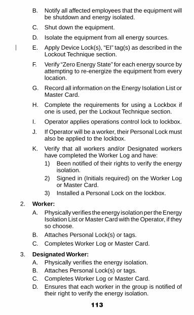
113
B. Notify all affected employees that the equipment will be shutdown and energy isolated.
C. Shut down the equipment.
D. Isolate the equipment from all energy sources.
E. Apply Device Lock(s), “EI” tag(s) as described in the Lockout Technique section.
F. Verify “Zero Energy State” for each energy source by attempting to re-energize the equipment from every location.
G. Record all information on the Energy Isolation List or Master Card.
H. Complete the requirements for using a Lockbox if one is used, per the Lockout Technique section.
I. Operator applies operations control lock to lockbox.
J. If Operator will be a worker, their Personal Lock must also be applied to the lockbox.
K. Verify that all workers and/or Designated workers have completed the Worker Log and have:
1) Been notified of their rights to verify the energy isolation.
2) Signed in (Initials required) on the Worker Log or Master Card.
3) Installed a Personal Lock on the lockbox.
2. Worker: A. Physically verifies the energy isolation per the Energy
Isolation List or Master Card with the Operator, if they so choose.
B. Attaches Personal Lock(s) or tags. C. Completes Worker Log or Master Card.
3. Designated Worker: A. Physically verifies the energy isolation. B. Attaches Personal Lock(s) or tags. C. Completes Worker Log or Master Card. D. Ensures that each worker in the group is notified of
their right to verify the energy isolation.

114
E. Ensures that each worker in the group has personally signed in on the Worker Log or Master Card.Note: The Designated Worker CANNOT complete the Worker Log or Master Card for the worker. Only the worker can sign it.
F. Adds their initials on the Worker Log or Master Card next to the worker’s name. Worker cannot assume they can work under the Designated Worker’s Personal Lock. There must be a mutual agreement between the worker and the Designated Worker and the Designated Worker must initial next to the worker’s name on the Worker Log or Master Card.
G. Signs (Initials) their name on the Worker Log or Master Card next to each worker’s name in their group.
Shift or Crew ChangesLockboxIn all cases where the Worker/Designated Worker (Authorized Employee) is leaving they shall remove their Personal Lock. If the equipment is not safe to start they may apply a Control Lock to protect the equipment and/or process. The Control Lock does not provide personal protection.1. Outgoing Operator: A. Communicates to the Incoming Operator the types
and locations of energy isolation devices (Energy Isolation List or Master Card);
B. Communicates the hazards involved if these devices are removed;
C. Reviews the Worker Log or Master Card; D. Removes their Personal Lock from the lockbox, if the
lock has been attached to the lockbox, and signs out on the Worker Log or Master Card; and,
E. Leaves the Control Lock in place on the lockbox.2. Incoming Operator: A. Reviews the Energy Isolation List/Master Card B. Reviews the Worker Log/Master Card C. If they are going to perform servicing or maintenance
under the Energy Isolation Standard, applies their Personal Lock and signs in on the Worker Log or Master Card.
D. Leaves the Control Lock in place on the lockbox.

115
3. Outgoing Designated Worker:The Designated Worker assumes full responsibility for the safety of the workers in their group. For this reason, the Designated Worker shall have control over who is in their group.
A. Ensures that each outgoing worker in their group completes the appropriate blocks on the Worker Log or Master Card, signing initials next to each worker’s name.
B. Removes their Personal Lock and signs out on the Worker Log or Master Card.
C. Reviews the Energy Isolation List/Master Card with the oncoming Designated Worker.
D. If the equipment is not safe to put back in service and there is not an oncoming Designated Worker, the Designated Worker may apply a Control Lock to the lockbox.
4. Incoming Designated Worker:
A. Reviews the Energy Isolation List or Master Card;
B. Physically verifies the energy isolation;
C. Attaches Personal Locks or tags;
D. Completes the appropriate blocks on the Worker Log or Master Card;
E. Ensures that each worker in their group is notified of the worker’s right to verify energy isolation and apply Personal Locks or tags if the worker wishes to do so;
and F. Ensures that each worker in their group completes
the appropriate block on the Worker Log or Master Card, signing initials by each worker’s name.
5. Outgoing Worker:
A. Communicates to the Incoming Worker the types and locations of energy isolation devices;
and,
B. The hazards involved if these devices are removed.

116
C. Signs out on the Worker Log or Master Card. D. Removes their Personal Locks and/or tags if they
have been attached. E. If the equipment is not safe to put back into service
and there is not an oncoming worker, the worker may apply a control lock to the lockbox.
6. Incoming Worker: A. Verifies isolations with the Operator if they so choose. B. Installs Personal Locks and/or tags, if not working
under a Designated Worker. C. Signs in on the Worker Log or Master Card. Obtains
approval from the Designated Worker to work under the Designated Worker’s Personal Lock.
When Work is Complete:1. Worker or Designated Worker: A. Notifies Unit Operator that work is completed. B. Verifies that all personnel in their group have signed
out by signing initials next to each worker’s name on the Worker Log or Master Card.
C. Signs out on the Worker Log or Master Card. D. Removes Personal Locks and/or tags.
2. Operator: A. Verifies that all worker locking devices and/or tags
have been removed and all personnel have signed out of the Worker Log or Master Card.
B. Removes Device Locks and/or tags. C. Dates and initials Energy Isolation List or Master
Card. D. Ensures personnel and equipment are clear and it is
safe to place the equipment in service. E. Removes locks, matches tag stubs to tags prior to
re-energizing.
F. Returns equipment to service.
G. Ensures the Master Card, Energy Isolation List and the Worker Log are filed per the facility’s administra-tive requirements.
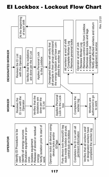
117
EI Lockbox - Lockout Flow ChartO
PE
RA
TOR
•Id
entif
yE
IPro
cedu
reto
be
used
•Id
entif
yal
lene
rgy
sour
ces
•S
hutd
own
equi
pmen
tor
pro-
cess
•Is
olat
ese
quip
men
t•
Rel
ease
ofs
tore
dor
res
idua
len
ergy
•V
erify
isol
atio
npr
ior
tos
tart
of
wor
k
Ope
rato
r lo
cks
all d
evic
es u
sing
de
vice
lock
s an
d/or
E
ITag
s
Put
s de
vice
lock
key
s(s)
/EI t
ag
stub
s in
side
lock
box
and
puts
co
ntro
l loc
k on
lock
box
Com
plet
es th
e E
I Lis
t with
all
pert
inen
t inf
orm
atio
n
Ver
ifies
that
all
wor
kers
and
/or
des
igna
ted
wor
kers
hav
e co
mpl
eted
the
wor
ker
log
WO
RK
ER
Rev
iew
s th
e E
I Lis
t with
the
Ope
rato
r
Ver
ifies
that
the
isol
atio
ns a
re
done
per
the
EI L
ist
App
lies
Per
sona
l Lo
ck to
the
Lock
-bo
x
Com
plet
es th
e w
orke
r lo
g
Wor
kers
are
au
thor
ized
to g
o to
wor
k
DE
SIG
NA
TE
D W
OR
KE
R
Rev
iew
s th
e E
I Lis
t w
ith th
e O
pera
tor
Ver
ifies
that
the
isol
atio
ns
are
done
per
the
EI L
ist
App
lies
Per
sona
l Loc
k to
the
Lock
box
At t
he b
egin
ning
of
eac
h sh
ift
Des
igna
ted
Wor
ker
will
ver
ify th
at
all p
eopl
e in
thei
r gr
oup
unde
rsta
nd
the
ener
gy is
olat
ion
and
have
com
-pl
eted
the
wor
ker
log
All
wor
kers
at e
nd o
f shi
ft•
Com
plet
eW
orke
rLo
g•
Rem
o ve
pers
onal
lock
s
Ope
rato
r at
end
of J
ob•
Re v
iew
sW
orke
rLo
g•
Rem
oves
con
trol
lock
from
Loc
kbox
• R
emo v
esd
evic
elo
cks
and
tags
•C
ompl
etes
EIL
ist
•N
otify
all
affe
cted
wor
kers
and
ret
urn
•eq
uipm
ent t
o se
rvic
e
R
ev. 1
1/10
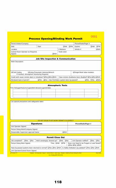
118
Process Opening/Blinding Work Permit
Permit Initiator/Company Phone/Radio/Pager #
Date Start � AM � PM Expires � AM � PM
Location # Workers Vehicle # � N/A
Control Room Operator as Required, Tools UsedSigned: � N/A
Job Site Inspection & CommunicationWork Description:
� Cold Cutting � Using Pneumatic Hammer/Wrench � Single Block Valve Isolation If checked, Atmospheric Monitoring Required
Could work cause remote alarm or shutdown? � Yes � No � N/A Have remote shutdowns been disabled? � Yes � No � N/A
Reviewed back of permit? � Yes � No Has Fire/Halon system been by-passed? � Yes � No � N/A
Atmospheric Tests Time %Oxygen %LEL H2S (ppm) N/A Benzene (ppm) Initials
List special precautions and safeguards taken:
DO NOT ISSUE IF HOT WORK PERMIT IS IN EFFECT
Signatures Phone/Radio/Pager #
Unit Operator Signed:
Person Doing Work/Company Signed:
Responsible Supervisor approval Name: � N/A
Permit Close Out
Job completed? � Yes � No Work area/equip. cleaned up? � Yes � No Unit Operator notifi ed? � Yes � No
Person Doing Work Signed: Time: � AM � PM Does Line Need to be Purged or Leak Tested? � Yes � No � N/A
Have by-passed systems been returned to normal? � Yes � No � N/A Is Safety Defeated Log updated? � Yes � No � N/A
Unit Operator/Control Room Signed:SFTY-002-777 Original - Unit Operator; Copy 2 - Control Room; Hard Copy - Posted or Held by Person Doing the Work Rev. 01/06
Q L Printing (907) 563-4743
0001

119
Process Opening/Blinding Work Permit
Permit Initiator/Company Phone/Radio/Pager #
Date Start � AM � PM Expires � AM � PM
Location # Workers Vehicle # � N/A
Control Room Operator as Required, Tools UsedSigned: � N/A
ControlRoomCopy
SFTY-002-777 Original - Unit Operator; Copy 2 - Control Room; Hard Copy - Posted or Held by Person Doing the Work Rev. 01/06
Q L Printing (907) 563-4743
0001

120
Any individual may invalidate this work permit at any time if they consider conditions or work methods to be unsafe.Anyone stopping work must: A. Inform the person doing the work; B. Remove the site copy of the permit; C. Return it to the Unit Operator giving reasons for their actions.
Y N N/A General Items To Consider 1. Spill prevention measures in place? 2. Communications checked?
3. Is equipment to be worked on correctly identifi ed?
4. Ladders/scaffold properly set?
5. Proper PPE?
6. Hot Work Permit in effect in area?
7. Equipment depressured and drained?
8. Rated blinds at the work site?
9. Vapor barrier identifi ed “NOT RATED”?
10. “T“ handle on all blinds?
11. Contingency plan in place if leakage occurs?
12. Has pressure build up test been completed?
13. Should Operator stay on site for duration of work?
14. Is valve able to be greased, has this been done?
15. Are all parts and equipment on site to minimize exposure time?
16. Is single block valve isolation approved?
17. Has job walk down been completed?
18. Has face to face communication taken place?
19. Is there a procedure and/or hazard assessment already in place for this scope of work?
IF JOB SCOPE OR CONDITIONS CHANGE - STOP THE JOB - REEVALUATECLOSE OUT PERMIT WITH CONTROL ROOM WHEN WORK IS COMPLETE!
Critical Activity or Considerations (Check all that apply)
� Barricades/Signs � Ground Disturbance (ACWR) � Subsidence � Confi ned Space Entry/Work � H2S / Benzene � Use of New Chemical � Energy Isolation Complete � Ignition Sources � Use of Pipe Plug / Bladder � Emergency Reporting/Safe Area � Lifting Operations (Critical/Blind Lift) � Vehicle Ops (Height/Backing/Congestion) � Energized Electrical System >50v � Lifting/Rigging � Ventilation Adequate � Environmental Concerns � Multiple, Complex Job/SIMOPS � Walking/Working Surface � Ergonomics/Body Position � Nitrogen Use (N2) � Work Close to Halon Discharge Nozzles � Eye Wash/First Aid Location � Pinch Points/Line of Fire � Work on Safety Systems � Falling Objects � Severe Weather (Wind, Temperature, Etc.) � Working at Heights Unguarded
Checked boxes should be addressed on front of form under “Special Precautions and Safeguards Taken”Potential Energy Sources (ES*)
� Electrical (E) � Gravity (G) � Energy of Motion (M) � Biological (B) � Pressure (P) � Chemical (C) � Heat or Cold (H/C) � Radiation (R)
Eliminate - Control - ProtectReview additional hazards not on list along with safeguards taken
Area of Concern ES* Potential Hazards Actions to Eliminate, Control or Protect

121
Process Opening/BlindingStandard
Purpose/ScopeThe purpose of this Standard is to minimize any exposures to personnel and property while opening and blinding any line or vessel which has contained a hydrocarbon product.
Opening and Blinding will be accomplished in accordance with the Energy Isolation Standard.
This Standard applies to all work on permanent surface equip-ment connected to wellhead valving.
This Standard does not cover:
1. Normal production operations on a regular basis. Examples of normal operations are replacing pressure gauges and pilots, changing orifice plates, venting through a valve, etc.
2. Drilling and well servicing, including well work over, coiled tubing and wire line activities.
Objectives1. Ensure adequate communication between all departments
concerned.
2. Institute a formal, consistent, and documented procedure.
Permit InitiationPermits may be initiated by anyone and will be done at the appropriate Control Room or other designated location.
A Unit Work Permit is not required for opening and blinding operations if an Opening and Blinding Work Permit is in effect.
During Process Opening/Blinding a Hot Work Permit is not required for the use of pneumatic/hammer wrenches. Required
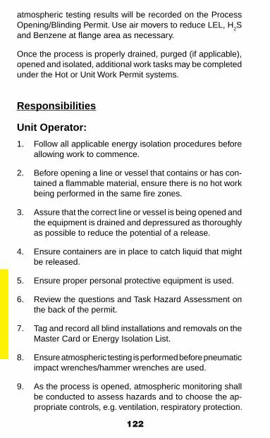
122
atmospheric testing results will be recorded on the Process Opening/Blinding Permit. Use air movers to reduce LEL, H2S and Benzene at flange area as necessary.
Once the process is properly drained, purged (if applicable), opened and isolated, additional work tasks may be completed under the Hot or Unit Work Permit systems.
Responsibilities
Unit Operator:
1. Follow all applicable energy isolation procedures before allowing work to commence.
2. Before opening a line or vessel that contains or has con-tained a flammable material, ensure there is no hot work being performed in the same fire zones.
3. Assure that the correct line or vessel is being opened and the equipment is drained and depressured as thoroughly as possible to reduce the potential of a release.
4. Ensure containers are in place to catch liquid that might be released.
5. Ensure proper personal protective equipment is used.
6. Review the questions and Task Hazard Assessment on the back of the permit.
7. Tag and record all blind installations and removals on the Master Card or Energy Isolation List.
8. Ensure atmospheric testing is performed before pneumatic impact wrenches/hammer wrenches are used.
9. As the process is opened, atmospheric monitoring shall be conducted to assess hazards and to choose the ap-propriate controls, e.g. ventilation, respiratory protection.

123
10. Contact Company Safety Representative prior to initiating cold cutting operations.
11. Sign and issue the permit.
12. After work is complete, inspect the work area and adjacent areas to determine they are in a safe condition and sign permit closeout section.
Control Room Operator or Drillsite/Wellpad Operator:
1. Ensure that facility operations, construction or maintenance will not be adversely affected by the proposed work activi-ties, and sign the permit.
2. Ensure that First-Line Supervisor’s or designee’s approval is obtained and a documented procedure outlining the work and safeout is used prior to proceeding with an opening and blinding job where pressure cannot be bled to zero, or the absence of pressure cannot be verified.
3. Notify the Unit Operator when the permit is closed out.
First-Line Supervisor:
1. Ensure all participants in the opening and blinding process have fulfilled their duties and responsibilities.
2. Ensure adequate precautions have been taken and give approval when satisfied that work can proceed safely if:
• Pressure cannot be bled to zero
• The absence of pressure cannot be verified or when single valve isolation must be used.
Person Doing the Work:
1. Read and understand the conditions of the Opening/Blinding Work Permit before starting work.
2. Advise other workers of any special precautions or condi-tions pertaining to the job.
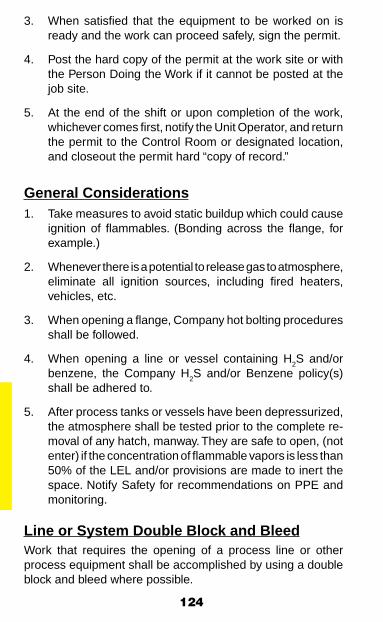
124
3. When satisfied that the equipment to be worked on is ready and the work can proceed safely, sign the permit.
4. Post the hard copy of the permit at the work site or with the Person Doing the Work if it cannot be posted at the job site.
5. At the end of the shift or upon completion of the work, whichever comes first, notify the Unit Operator, and return the permit to the Control Room or designated location, and closeout the permit hard “copy of record.”
General Considerations1. Take measures to avoid static buildup which could cause
ignition of flammables. (Bonding across the flange, for example.)
2. Whenever there is a potential to release gas to atmosphere, eliminate all ignition sources, including fired heaters, vehicles, etc.
3. When opening a flange, Company hot bolting procedures shall be followed.
4. When opening a line or vessel containing H2S and/or benzene, the Company H2S and/or Benzene policy(s) shall be adhered to.
5. After process tanks or vessels have been depressurized, the atmosphere shall be tested prior to the complete re-moval of any hatch, manway. They are safe to open, (not enter) if the concentration of flammable vapors is less than 50% of the LEL and/or provisions are made to inert the space. Notify Safety for recommendations on PPE and monitoring.
Line or System Double Block and BleedWork that requires the opening of a process line or other process equipment shall be accomplished by using a double block and bleed where possible.

125
Note: A double Block and Bleed is not an approved isolation for a confined space entry or hot work, (reference “Confined Space and Hot Work Standard”).
Single Valve Isolation
When single valve isolation must be used, the responsible Supervisor’s (or designee’s) approval must be obtained and their name printed on the Opening and Blinding Work Permit. Approval can be obtained in person and/or verbally over the phone or radio.
Blind Requirements
1. Blinds specified shall conform to Company-adopted design specifications or shall be temperature/pressure design rated blinds.
2. A blind, other than a spectacle blind, must have a long enough “T” handle attached to extend at least two (2) inches beyond pipe flanges in order to eliminate any doubt whether the in-line device is a blind or a spacer.
3. Blinds, blind flanges, and spacers must have the proper rating stamped on the handle.
4. All permanent blinds and spacers that are installed shall have new gaskets which conform to current Company design specifications.

126
5. All flange make-ups shall have the bolts properly torqued and torqueing sequence shall be in accordance with cur-rent Company specifications.
6. No blind shall be installed or removed, unless it can be accomplished safely. Blinding should be as close to the vessel/work as possible, however, when blinding as close to the vessel/work as possible creates additional hazards or is impractical, blinds can be applied at another location with the approval of the Company First Line Supervisor and Company Safety Representative. The approvals to apply the blind at another location will be documented on the Energy Isolation Procedure.
7. Tapped blind flanges shall be used where possible. Design and construction standards should require consideration of a tapped blind flange behind a single block valve isolation when a blind flange is installed.
Duration of Permits/Permit Close Out
Permits will be in effect until job completion but will not extend beyond the end of the shift in which the permits were issued.

127
Control # Date
DANGERENERGY ISOLATION ONLYDO NOT OPERATE while this tag is attached:
Full description of why tagis attached (See Other Side)
Master Card Number:
Attached By:
Contact Number:
Only to be removed by person attaching orauthorized representative98P112
0001
0001
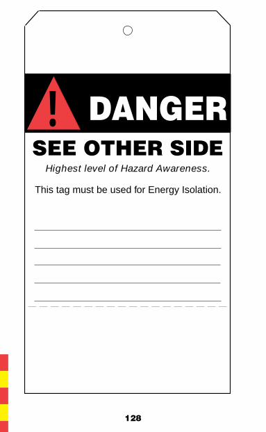
128
DANGER SEE OTHER SIDE
Highest level of Hazard Awareness.
This tag must be used for Energy Isolation.
!
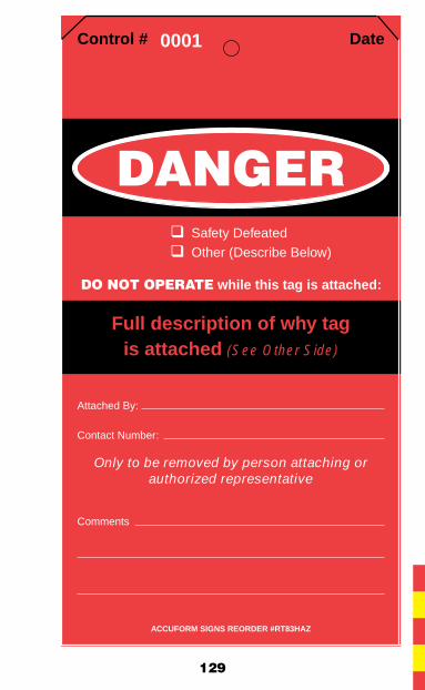
129
Control # Date
DANGER� Safety Defeated� Other (Describe Below)
DO NOT OPERATE while this tag is attached:
Full description of why tagis attached (See Other Side)
Attached By:
Contact Number:
Only to be removed by person attaching orauthorized representative
Comments
ACCUFORM SIGNS REORDER #RT83HAZ
0001
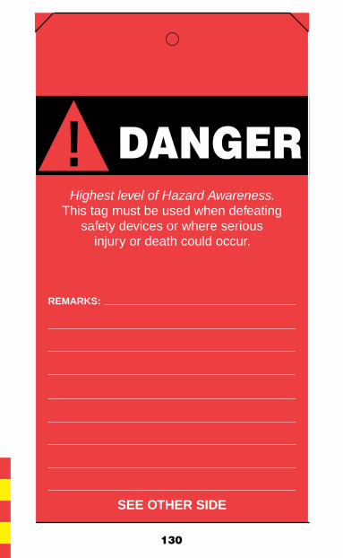
130
DANGER Highest level of Hazard Awareness.
This tag must be used when defeatingsafety devices or where serious
injury or death could occur.
REMARKS:
SEE OTHER SIDE
!

131
Date
CAUTION� Device not in normal position
Full description of why tagis attached
Attached By:
Contact Number:
98P110
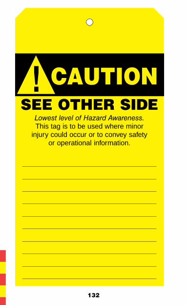
132
CAUTIONSEE OTHER SIDE
This tag is to be used where minorinjury could occur or to convey safety
or operational information.
!
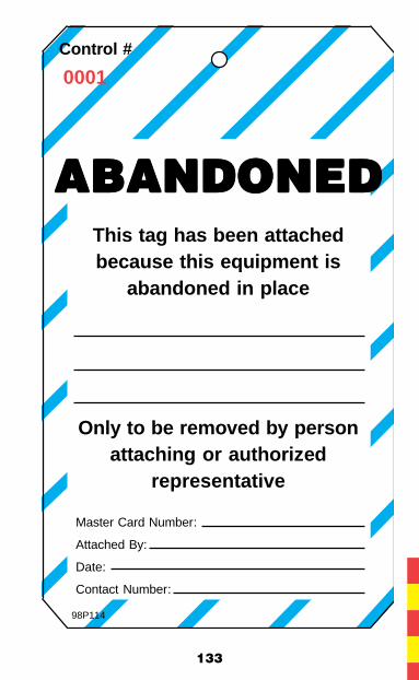
133
Control #
ABANDONEDABANDONEDABANDONEDABANDONEDABANDONEDThis tag has been attachedbecause this equipment is
abandoned in place
Only to be removed by personattaching or authorized
representative
Master Card Number:
Attached By:
Date:
Contact Number:
98P114
0001
134
Tagging & FlaggingStandard
Purpose/ScopeThe purpose of this Standard is to establish tagging and flagging requirements and to make employees aware of temporary haz-ards, special conditions or the abnormal position of equipment.
ResponsibilitiesOperators are responsible for knowing about all tags and flags located in their area. This does not preclude anyone from adding a tag or flag in an area as long as the Unit Operator or person-nel responsible for the area are informed as soon as possible.
Accident Prevention TagsAccident Prevention Tags are used to identify temporary hazardous conditions and provide a message to employees with respect to those conditions. Accident Prevention Tags are hereafter referred to as “tags.”
Danger tags will be used when there is a possibility that a hazard could present a threat of death or injury to an employee or defeating safety devices.
Energy Isolation tags will be used when designating devices that should not be operated during energy isolation of equip-ment as per the Energy Isolation Standard.
Caution tags will be used where a minor incident could occur due to a hazard and:
• To convey safety related information, or
• To convey operational information.
Abandoned Equipment tags will be used where equipment has been abandoned in place.
135
FlagsThree colors of flagging are used to draw attention to specific items or conditions.
Orange flagging is used to:
• Draw attention to tags not readily visible, and
• Identify non-normal position of operating equipment.
For NON-ENERGY ISOLATION situations, orange flags without tags shall be used when equipment is temporarily placed in a non-normal operating position and Operations personnel placing the equipment in a non-normal position remain at the facility. If an Operator must leave the facility (i.e., shift change) and the equipment is flagged in a non-normal position, then a “caution” tag must be hung at the same location.
Blue flagging is used to identify specific pieces of equipment or locations of future work (x-rays, UT inspection points, tie-ins, hot taps, demolition work, etc).
Yellow flagging is used to mark leaks (gas/liquid).
Specific Considerations1. Tagging and flagging are visual elements to make people
aware of temporary hazards or to convey useful infor-mation. They are not substitutes for careful checking of each device prior to decommissioning of equipment or operational change.
2. Tags must be able to withstand the environmental condi-tions in which they are placed.
3. Tags must be secured to devices in such a way that they cannot be accidentally detached. Energy Isolation tag-ging attachment devices (other than locks), shall be non-reusable, attachable by hand, self locking, and capable of withstanding 50 lbs. of force.
136
4. Tags must convey the following information:
• The date the tag was attached.
• Explanation of the conditions associated with the placement of the tag.
• Who (person/position) attached the tag. Tags must be identifiable to a unique responsible individual on-site by indicating a name, pair of names, or by a unique job position.
• The contact number of the (person/position) attaching the tag.
5. Equipment cannot be operated as long as a “Danger” tag is attached. The tag may only be removed by the person/position attaching the tag or an authorized representative of that person/position. See Energy Isolation Standard if applicable.
SIGN CLASSIFICATION AND REQUIREMENTSOSHA and ANSI classify safety signs according to use. Their definitions are very similar. OSHA has three classifications of signs:
1. Danger Signs – Indicate immediate danger and that special precaution are necessary. OSHA also specifies that the red, black and white colors used for Danger signs be in accordance with ANSI Z53.1-1967.
2. Caution Signs – Warn against potential hazards or caution against unsafe practices. OSHA specifies that the standard color for Caution signs shall have a yellow background, black panel and yellow letters. All letters used against the yellow background shall be black. The colors must be accordance with ANSI Z53.1-1967.
3. Safety Instruction Signs – Used where there is a need for general instructions and suggestions relative to safety measures. OSHA specifies that the standard color for Safety Instruction signs shall be a white background, green panel and white letters. Any letters used on the white background shall be black. The colors must be in accordance with ANSI Z53.1-1967.

137
AR
CO
Ala
ska,
Inc.
BP
Exp
lora
tio
n (
Ala
ska)
, In
c.
De
fea
ted
Sa
fety
De
vic
e L
og
De
fea
ted
Sa
fety
De
vic
e L
og
De
fea
ted
Sa
fety
De
vic
e L
og
De
fea
ted
Sa
fety
De
vic
e L
og
De
fea
ted
Sa
fety
De
vic
e L
og
All
empl
oyee
s m
ust b
e aw
are
of t
he im
pact
to
proc
ess
safe
ty b
efor
e de
feat
ing
any
safe
ty d
evic
e/sy
stem
.
Def
eate
d D
evic
eD
ate
Met
ho
dR
easo
nD
aily
Ap
pro
val
TA
G #
:R
ET
UR
N T
O
DAT
ED
ATE
DAT
ED
ATE
DAT
ED
ATE
DAT
ES
ER
VIC
E
DE
VIC
E:
OP
ER
SU
PV
OP
ER
SU
PV
OP
ER
SU
PV
OP
ER
SU
PV
OP
ER
SU
PV
OP
ER
SU
PV
OP
ER
SU
PV
OP
ER
SU
PV
TIM
E:
D
OP
ER. A
RE
AN
TA
G #
:R
ET
UR
N T
O
DAT
ED
ATE
DAT
ED
ATE
DAT
ED
ATE
DAT
ES
ER
VIC
E
DE
VIC
E:
OP
ER
SU
PV
OP
ER
SU
PV
OP
ER
SU
PV
OP
ER
SU
PV
OP
ER
SU
PV
OP
ER
SU
PV
OP
ER
SU
PV
OP
ER
SU
PV
TIM
E:
D
OP
ER. A
RE
AN
TA
G #
:R
ET
UR
N T
O
DAT
ED
ATE
DAT
ED
ATE
DAT
ED
ATE
DAT
ES
ER
VIC
E
DE
VIC
E:
OP
ER
SU
PV
OP
ER
SU
PV
OP
ER
SU
PV
OP
ER
SU
PV
OP
ER
SU
PV
OP
ER
SU
PV
OP
ER
SU
PV
OP
ER
SU
PV
TIM
E:
D
OP
ER. A
RE
AN
TA
G #
:R
ET
UR
N T
O
DAT
ED
ATE
DAT
ED
ATE
DAT
ED
ATE
DAT
ES
ER
VIC
E
DE
VIC
E:
OP
ER
SU
PV
OP
ER
SU
PV
OP
ER
SU
PV
OP
ER
SU
PV
OP
ER
SU
PV
OP
ER
SU
PV
OP
ER
SU
PV
OP
ER
SU
PV
TIM
E:
D
OP
ER. A
RE
AN
TA
G #
:R
ET
UR
N T
O
DAT
ED
ATE
DAT
ED
ATE
DAT
ED
ATE
DAT
ES
ER
VIC
E
DE
VIC
E:
OP
ER
SU
PV
OP
ER
SU
PV
OP
ER
SU
PV
OP
ER
SU
PV
OP
ER
SU
PV
OP
ER
SU
PV
OP
ER
SU
PV
OP
ER
SU
PV
TIM
E:
D
OP
ER. A
RE
AN
TA
G #
:R
ET
UR
N T
O
DAT
ED
ATE
DAT
ED
ATE
DAT
ED
ATE
DAT
ES
ER
VIC
E
DE
VIC
E:
OP
ER
SU
PV
OP
ER
SU
PV
OP
ER
SU
PV
OP
ER
SU
PV
OP
ER
SU
PV
OP
ER
SU
PV
OP
ER
SU
PV
OP
ER
SU
PV
TIM
E:
D
OP
ER. A
RE
AN
TA
G #
:R
ET
UR
N T
O
DAT
ED
ATE
DAT
ED
ATE
DAT
ED
ATE
DAT
ES
ER
VIC
E
DE
VIC
E:
OP
ER
SU
PV
OP
ER
SU
PV
OP
ER
SU
PV
OP
ER
SU
PV
OP
ER
SU
PV
OP
ER
SU
PV
OP
ER
SU
PV
OP
ER
SU
PV
TIM
E:
D
OP
ER. A
RE
AN
TA
G #
:R
ET
UR
N T
O
DAT
ED
ATE
DAT
ED
ATE
DAT
ED
ATE
DAT
ES
ER
VIC
E
DE
VIC
E:
OP
ER
SU
PV
OP
ER
SU
PV
OP
ER
SU
PV
OP
ER
SU
PV
OP
ER
SU
PV
OP
ER
SU
PV
OP
ER
SU
PV
OP
ER
SU
PV
TIM
E:
D
OP
ER. A
RE
AN
Sup
ervi
sor
Sup
erin
tend
ent
Fie
ld M
anag
er(s
igna
ture
req
uire
d if
over
90
days
)(s
igna
ture
req
uire
d if
over
180
day
s)
QL
PR
INT
ING
(907
) 56
3-47
43

138
Defeated Safety DevicesStandard
Purpose/ScopeThe purpose of this Standard is to establish a procedure to authorize, record and monitor all Defeated Safety Devices.
ObjectivesEnsure adequate communication during times when safety devices are inoperative.
Defeated Safety Device Log A Defeated Safety Device Log (DSD Log) shall be maintained in the designated facility location specifying date, tag number, device defeated, how defeated, reason and authorization. Items that are under the continuous direct control of the authorized person and are returned to service prior to the end of the shift are not required to be entered on the Defeated Safety Device Log.
ResponsibilitiesUnit Operator:1. At the beginning of each shift, initial the master log to
acknowledge awareness of the devices being defeated and length of time out of service.
2. Shall notify Supervisor, defeat or give permission to defeat the safety device, and record in the master log as soon as possible.
3. Attach a “Danger – Do Not Operate” tag to the device or control panel. Tag shall identify the defeated device, reasons why defeated, operator’s name, and date. When instrumentation readouts or indicators are affected, a “Danger – Do Not Operate” tag shall also be posted at those locations.
4. Inform the persons doing the work on the status of the defeated device.
5. Ensure all safety devices are returned to normal operating condition prior to completing the job.

139
6. Record the date when the safety device was returned to service on the Defeated Safety Device Log.
Control Room Operator or Drillsite/Wellpad Operator:Be aware of the status of any defeated safety devices and how it may affect the overall operation.
Operations First-Line Supervisor:
1. Initial the DSD Log daily to indicate awareness of the devices being defeated and length of time out of service.
2. Be responsible for operating with a safety device which has been defeated. Ensure that impact to process safety as well as personnel safety and health is acceptable.
Duration
The Operations Manager’s signature shall be required on the DSD Log if a device is defeated for 90 days, and will be required every 90 days thereafter.
The Field/Senior Level Manager’s signature shall be required on the DSD Log after 120 days, and every 120 days thereafter.
Special Considerations
Short-term operation of a facility without Halon protection requires the approval of the Operations First-Line Supervisor except during routine fire and gas system maintenance or PMs.
Continuous operation of a facility with a defeated fire suppres-sion/detection system/alarm system such as Halon, gas detec-tion, etc., requires the approval of the appropriate manager.
Note: Continuous operation is defined as any twelve-hour period from the time the system became inoperable.
Jumpers that impact safety devices shall be recorded on the DSD Log.

140
Area Civil Work Request
Inspection Clearance For Date:Excavation/Trenching/Drilling
Scheduled Shift of Work:
REQUEST ACWR Expires On:
Location: Initiator: Company Doing Work: Phone/PagerRadio:
Work Description:
*Note: This is not a permit to work, a work permit must also accompany the ACWR.*Note: A copy of this ACWR must be on-site during activities.
Pre-job Inspection
SURVEYING CONTRACTOR CLEARANCE
IS EXCAVATION MARKED? YES NO SIGNATURE DATE
FIELD LOCATE REQUIRED? YES NO (ALSO, INITIAL BACK SECTION OF ACWR)
ELECTRICAL CLEARANCE
FIELD LOCATE REQUIRED? YES NO
IS LOCATE COMPLETE? YES NO SIGNATURE DATE
HAVE ALL SPECIAL PRECAUTIONS BEEN IDENTIFIED? YES NO (ALSO, INITIAL BACK SECTION OF ACWR)
COMMUNICATIONS CLEARANCE
FIELD LOCATE REQUIRED? YES NO
IS LOCATE COMPLETE? YES NO SIGNATURE DATE
HAVE ALL SPECIAL PRECAUTIONS BEEN IDENTIFIED? YES NO (ALSO, INITIAL BACK SECTION OF ACWR)
FACILITY ENGINEERING CLEARANCE
FIELD LOCATE REQUIRED? YES NO
IS LOCATE COMPLETE? YES NO SIGNATURE DATE
HAVE ALL SPECIAL PRECAUTIONS BEEN IDENTIFIED? YES NO (ALSO, INITIAL BACK SECTION OF ACWR)
ENVIRONMENTAL CLEARANCE
HAVE ALL SPECIAL PRECAUTIONS BEEN IDENTIFIED? YES NO SIGNATURE DATE
(ALSO, INITIAL BACK SECTION OF ACWR)
SAFETY CLEARANCE
IS CONFINED SPACE PERMIT REQUIRED? YES NO SIGNATURE DATE
HAVE ALL SPECIAL PRECAUTIONS BEEN IDENTIFIED? YES NO (ALSO, INITIAL BACK SECTION OF ACWR)
REMARKS AND EXPECTATIONS:
APPROVAL
PERSON DOING THE WORKSIGNATURE DATE
FIRST-LINE SUPERVISOR OF PERSON DOING THE WORKSIGNATURE DATE
COMPANY AREA FIRST-LINE SUPERVISORSIGNATURE DATE
SFTY-002-782 Rev. 01/06Q L Printing (907) 563-4743

141
142
Excavating, Trenching, and Drilling Standard
Area Civil Work Request (ACWR)
Purpose/Scope
This Standard defines administrative requirements that shall be followed to authorize excavation, trenching, burying, pile driving, conductor and VSM drilling, and any other operations which could damage covered or buried cables and pipelines. A ground disturbance less than 12 inches deep does not re-quire an ACWR. If there are any questions regarding potential to contact buried utilities less than 12 inches at the specific location, contact the area supervisor to determine whether an ACWR needs to be completed.
Objectives
1. Ensure adequate communication between all personnel prior to excavation, digging, trenching, drilling or clearing.
2. Institute a formal, consistent, and documented procedure.
3. Ensure surveyed as-builts and formal documentation of all changes are completed.
Permit Initiation
The Company or Contractor Representative responsible for performing the work will initiate the Area Civil Work Request (ACWR). A minimum of seventy-two (72) hours is normally required to complete the entire ACWR process.
A drawing specifically showing all underground work to be done shall be attached to the ACWR when initiated.
The Permit Initiator shall attach a copy of the completed ACWR to the appropriate Work Permit. The Permit Initiator shall retain the completed original ACWR for one (1) year.
143
ResponsibilitiesAll inspection signatures shall be obtained prior to the approval signatures. The inspection signatures do not have to be ob-tained in the order in which they are listed with the exception of the Surveying Contractor which shall be obtained first, and the Safety signature which shall be obtained last. The approval signatures must be obtained in the order they are listed.
Surveying Contractor:• Shall verify that the project area has been marked properly,
if applicable, and that there are no conflicts with buried items in the area.
• Shall coordinate as-built scheduling with the contractor.
• Shall ensure that the drawings/manuals are updated and kept current.
• Do not sign in the signature block until it is safe to proceed.
Electrical Representative:• Shall verify that no electrical or control cables will be af-
fected by the proposed activity (no locate required). Check ‘Field Locate Required?’ Box ‘No’ on the front of the ACWR.
• Shall verify that all electrical or control cables within 15 feet of the project area (locate required) are clearly marked for location and depth. Check ‘Field Locate Required?’ Box ‘Yes’ on the front of the ACWR.
• Shall be responsible for energy isolation of any energized cables within 15 feet of the project area, unless a central shop or facility electrician is on-site for the work activity.
• Do not sign in the signature block until it is safe to proceed.
Communications Representative:• Shall verify that no communications cables will be af-
fected by the proposed activity (no locate required). Check ‘Field Locate Required?’ Box ‘No’ on the front of theACWR.

144
• Shall verify that all communications cables within 15 feet of the project area (locate required) are clearly marked for location and depth. Check ‘Field Locate Required?’ Box ‘Yes’ on the front of the ACWR.
• Do not sign in the signature block until it is safe to proceed.
Facility Engineering Representative:• Shall verify that no pipelines, liners, or other utilities will
be affected by the proposed activity (no locate required). Check ‘Field Locate Required?’ Box ‘No’ on the front of the ACWR.
• Shall review that all buried pipelines, liners, or other utili-ties within 15 feet of the project area (locate required) are clearly marked for location and depth. Check ‘Field Locate Required?’ Box ‘Yes’ on the front of the ACWR.
• Do not sign in the signature block until it is safe to proceed.
Environmental Department:• Shall review and add any environmental precautions.
• Shall review all precautions taken to ensure there are no conflicts in the project area.
• Shall sign the ACWR, acknowledging their familiarity with the work and steps taken to avoid environmental incidents.
Company Safety Department:• Shall review and add any safety precautions.
• Shall sign the ACWR, acknowledging their familiarity with the work and steps taken to avoid unplanned contact with existing utilities.
• Shall review all remarks and expectations with the initiator to ensure all precautions are addressed.
Person doing the work:• Shall review all precautions taken to ensure there are no
conflicts in the project area.

145
• Shall sign the ACWR, acknowledging their familiarity with the work and the steps taken to avoid unplanned contact with existing utilities.
• Shall ensure all remarks and expectations have been addressed.
First-Line Supervisor of the person doing the work:• Shall review all precautions taken to ensure there are no
conflicts in the project area.
• Shall sign the ACWR, acknowledging their familiarity with the work and the steps taken to avoid unplanned contact with existing utilities.
• Shall ensure all remarks and expectations have been addressed.
Company Area First-Line Supervisor:• Shall review all precautions taken to ensure there are no
conflicts in the project area.
• Shall sign the ACWR, acknowledging their familiarity with the work and the steps taken to avoid unplanned contact with existing utilities.
• Shall ensure all remarks and expectations have been addressed.
Special Considerations1. For excavations 6 feet or more in depth, perimeter bar-
ricades, guardrail systems, or covers shall be provided to protect personnel. Open drill holes (VSM’s, module pilings, conductors, etc.,) shall be covered with plywood covers at least 1-1/8 inches thick with handles, cones, and appropriate warning markings.
2. Walkways shall be provided where employees or equipment are required to cross over excavations. Guardrails shall be provided where walkways are 6 feet or more above lower levels.

146
3. No power equipment excavation operation shall be permit-ted within 3 feet of any buried cable or other utility, unless it has been de-energized and physically located by hand excavation methods.
4. No power equipment excavation operation shall be permit-ted within 3 feet of any buried pipeline, pit/curtain liner or other non-energized utility unless it has been physically located by hand excavation methods.
5. The Excavation Competent Person shall evaluate all excavations daily if employees are going to work or enter the excavation. The evaluation will be documented.
6. Excavation deeper than 4 feet shall be evaluated by the Company Safety Representative per Confined Space Entry Standard.
7. The walls and faces of all excavations in which person-nel are exposed to danger from moving ground shall be guarded by shoring, sloping or an equivalent means in accordance with applicable regulations.
8. The Fire Department shall be notified by Operations of any excavation which may impede access to facilities, drillsites/wellpads, etc. Alternate traffic routing shall be provided where possible.
9. Prior to backfilling a trench or excavation where new utilities or items are installed, the surveying contractor shall be contacted. The trench shall be as-built showing location, depth and description of buried items before backfilling is allowed. Consider use of identification markings above buried items.
10. All buried items, utilities, etc. shall be as-built and appro-priately documented.
147
Snow Removal StandardPurpose / ScopeThis Standard defines requirements that shall be followed to safely remove snow from areas including, but not limited to, common traffic areas such as roadways, parking lots and around facilities, areas near operational equipment and any other areas where snow covered cables, pipelines, equipment or other hazardous obstructions may be present.
Snow removal where hazardous obstructions exist will require a Unit Work Permit. It is important to ensure that all information identifying hazards is accurate and current.
Snow removal operations in common traffic areas, such as roadways, parking lots, and around facilities will not require a Unit Work Permit, however, unit operator notification prior to accessing and departing pads is required.
Vehicles and equipment involved in snow removal activities within 10 feet of a classified area shall require Operator noti-fication but not a Hot Work Permit.
Objective1. Ensure the area where the snow removal work is to be
done is inspected.
2. Provide communication with all departments concerned.
3. Document all hazardous conditions and special require-ments of the work area.
An annual review will be conducted to ensure proper markings of pipelines, cables, equipment or other obstructions where there is a possibility that accumulated snow will need to be removed. This review includes updating and distribution of the Equipment Operations Guides (EOG).
Permit InitiationA Unit Work Permit for snow removal may be initiated by any-one and will be done at the appropriate control room, drillsite/wellpad, or other designated location.
148
ResponsibilitiesUnit Operator/Issuing Authority:
1. Discuss special precautions and conduct a site review with the person(s) responsible for doing the snow removal prior to issuing a Unit Work Permit.
2. Complete and sign the Unit Work Permit authorizing snow removal as required.
3. Promptly report and investigate/evaluate the extent of any damage that occur during snow removal.
4. Participate in the annual review to verify the accuracy of current drawings and identification of known hazards.
5. Ensure pipelines, cables, equipment or other obstruc-tions as identified in the EOG are properly marked with substantial snow poles or equivalent.
6. Notify Roads & Pads group when any pipeline, cable or other obstruction is in need of a new or replaced marker and follow-up to ensure markers are installed prior to snow accumulation. Work to be completed via the Work Order system.
Roads and Pads Representative:1. Participate in the annual review to verify the accuracy of
current drawings used in the EOG.
2. Responsible for the field wide distribution of the updated EOG’s on an annual basis.
3. Contact the Unit Operator or other designated responsible person prior to conducting snow removal.
4. Initiate Unit Work Permit as required and participate in site review and discussions with operations personnel prior to starting snow removal activity.
5. Be alert to any obstructions that may not be previously identified or marked and notify operations personnel of the location and need for snow poles or markers.

149
6. Immediately notify operations personnel should powered equipment contact/damage facility lines, cables or equip-ment during snow removal.
7. Maintain updated Equipment Operations Guide / Hazard Review books and review as part of the Unit Work Permit as required.
Surveying Contractor:1. Maintain a current detailed drawing of the each operating
area that includes pipeline and cable locations.
2. Participate in the annual review to verify the accuracy of current drawings.
Electrical Representative:1. Participate in the annual review to verify the accuracy of
current drawings.
Engineering Representative:1. Participate in the annual review to verify the accuracy of
current drawings.
Special Considerations1. Snow poles and/or location markers shall be placed 3’-
4’ out from the accessible side of pipelines and power cables.
2. A qualified electrician must provide onsite approval when using power equipment to remove snow within 15’ of unguarded, energized overhead electrical lines.
3. No power equipment snow removal operations shall be permitted within 3’ of any utility cable or energized elec-trical cable unless it is clearly visible to the Equipment Operator, or has been marked with snow poles and/or location markers, or unless it has been de-energized and physically located by hand excavation methods.

150
4. No power equipment snow removal operations shall be permitted within 3’ of any energized electrical cable 600V or greater unless it is clearly visible to the Equipment Operator, or has been marked with snow poles and/or location markers; and a ground spotter is employed to assist with the operation.
5. No power equipment snow removal operations shall be permitted within 3’ of any pipeline, pit / curtain liner, or other non-energized utility unless it is clearly visible to the Equipment Operator, or has been marked with snow poles and/or location markers
6. Ensure adequate precautions are taken to account for the release of stored energy when removing overburden from snow loaded pipelines. Do not use powered mechanical equipment to remove snow from the top of a buried pipeline without prior approval from Production/Area Supervisor.
7. When infrastructure (e.g. pipelines, energized equipment, etc.) normally left snow covered must be exposed using methods that potentially could cause damage, perform the following tasks in addition to the other requirements of this Standard:
• Consult applicable drawings to aid in understanding what obstructions are in the affected area.
• For planned work, mark all infrastructure within the work zone and 10 ft. outside it in advance of the work whenever such locate can be accomplished before snow covers it.
• When the work requires exposing snow covered infrastructure, the entire work zone and 10 ft. outside it must be probed using a 1 foot grid pattern in order to develop a complete profile of the area.
• Use snow poles and/or location markers to delineate the infrastructure.
• In the area where snow is to be removed, use offset markers to easily relocate obstructions as each layer of snow is removed. Do not assume the position of any obstruction until it is once again clearly delineated.

151
8. Snow blower operators shall not direct snow plume toward electrical substations, transformers, overhead lines and structures, cable trays and other electrical apparatus. If the plume cannot be directed away from the equipment due to wind conditions, snow removal should be stopped or performed by other types of heavy equipment.
9. Snow blower operator shall blow snow in designated area(s) in accordance with the Equipment Operations Guide / Hazard Review book.
152
Oversize Vehicle Standard
Purpose/ScopeThis Standard establishes requirements to minimize risk to personnel, motor equipment, electrical transmission lines, and bridge structures from oversized motor vehicles on Company controlled roads.
Objectives
Establish communications with appropriate security, electrical maintenance, engineering, logistics, and emergency response personnel.
Responsibilities
Vehicle Operator
1. The traction vehicle of any load 14 feet or wider shall have a lighted, amber rotating beacon prominently displayed. Wide load signs or markers must be attached to the unit and be clearly visible to traffic approaching from the front and from the rear. Sections of the load protruding beyond the vehicle width must be lit by markers or spotlights when traveling in darkness.
2. An escort is required for a vehicle which has any of the following characteristics:
• Width between 16 feet and 20 feet requires 1 escort unit.
• Width of 20 feet or wider is considered impassable and requires 2 escort units.
• 25feetorhigher.
• Vehicle weight that may exceed posted weight limits.
153
3. Contact one of the following if an escort is required:
• Kuparuk Field Services.
• Beluga River Supervisor.
4. Strictly observe posted bridge load limits and speed limits.
Escort1. Shall compare the vehicle height with the electrical over-
head line clearances.
2. Shall lay out a route that will encounter the least number of overhead crossings.
3. If any electrical lines come within 15 feet in any direction of the anticipated move, the escort will contact the ap-propriate Electrical Representative.
4. If the vehicle weight exceeds posted bridge load limits, the escort shall contact an Engineering Representative.
Electrical Representative1. Shall make a complete study of the location in relation to
the overhead lines, and a safe plan shall be developed to move the load under the line.
2. When the equipment arrives at the low overhead crossing, he/she will have the authority and responsibility to safely move the equipment under the crossing.
3. The load speed while traveling under the power line shall be no more than a walking pace (3 mph).
4. If an outage is required or the lines need to be dropped, appropriate supervision must be notified.
Engineering1. Is required to perform a structural analysis for any bridge
crossing in excess of the posted load limit.
2. Shall verify vehicle weight to ensure proper load data for the structural analysis.

154
Special Considerations
Module Movements and Road Blocking:
Movement of modules to work locations must be coordinated with the Electrical Supervisor, Fire Chief, Medical Director, Equipment Operations Supervisor, Project Logistics Coordina-tion, and the Dock Master, with a minimum of 24 hours notifica-tion to allow the affected Operations Supervisor to be notified.
155
Hydrogen Sulfide (H2S)Standard
PurposeThe purpose of this Standard is to establish and maintain a safe environment for personnel working in areas with the potential for encountering hydrogen sulfide (H2S) gas through establishment of uniform operating standards and controls.
Refer to the specific Company Hydrogen Sulfide Standards and/or procedures for definitions, process sampling procedures, identification of H2S designated areas, signage, detection and alarm systems, and safe work practices applicable for facilities operated by each Company.
Responsibilities
Unit Operator:
1. Perform H2S gas checks necessary to characterize condi-tions where workers may be exposed to H2S.
2. Note on any permits where H2S could be present.
3. Check that personnel are using personal monitors in H2S designated areas.
4. Check that personnel working in areas with air concentra-tions exceeding 10 ppm H2S in worker breathing zones are using supplied air respirators.
First-Line Supervisor:
Ensure all H2S related activities within their scope of respon-sibility are in accordance with Company Standards.
Company or Contractor Work Group Leader:
1. Ensure personnel performing work in “H2S Designated Area” have received H2S training. Individuals shall provide evidence of current H2S training upon request.
156
2. Provide a pre-job review with personnel that may be exposed to H2S, highlighting special safety precautions required for the job. This includes facility alarms, evacu-ation routes, assembly points, etc.
3. Provide required protective equipment and personal H2S monitors while working in “H2S Designated Area.”
4. Be cognizant of the wind direction and choose an evacu-ation path accordingly.
5. Conduct a personnel head count after an evacuation in response to an H2S or gas alarm and report status to the Control Room Operator or Drillsite/Wellpad Operator, or appropriate authority.
6. Assign a trained Back-up Person, with ready access to supplied breathing air, when working in atmospheres of 10 ppm of H2S or greater.
Person Doing the Work:1. Know and understand the H2S and other facility alarms.
2. Provide evidence of required H2S training upon request.
3. Obtain and have the ability to properly use supplied breath-ing air apparatus and personal H2S monitors, if required to assist in rescue or facility isolation.
4. Report to the designated briefing area and be accounted for upon hearing an H2S or gas alarm.
5. If you find a situation with H2S levels of 10 ppm or greater in the atmosphere, leave the area at once and notify the appropriate operations personnel. Do not attempt to stop a leak, correct a situation, or perform rescue without don-ning a Self Contained Breathing Apparatus (SCBA) and having back-up personnel and proper equipment standing by.

157
“H2S Designated Area”Operating Requirements
Designated Area
Modules and facilities will be designated as H2S areas when they contain a process stream with H2S concentrations in the vapor phase greater than 100 ppm. The designated areas will be identified by a sign. Well pads and drill sites with one or more wells having greater than 100 ppm H2S will be posted with a notice on the entrance warning that some facilities on the pad are “H2S Designated Areas.”
Notification
For entrance into H2S Designated Areas, prior approval is required from the responsible designated authority.
Visitors
1. Escorted visitors will rely on the escort for compliance with the H2S Standard.
2. Unescorted visitors will be required, at a minimum, to have basic awareness level training or orientation. Advanced training may be required as determined by the First-Line Supervisor based on length of exposure and operating conditions.
Respiratory Protection
1. Supplied air (SCBA in a positive pressure mode, or airline unit with 5 minute escape bottle) is required to be worn whenever entering into an H2S atmosphere over 10 ppm.
2. Emergency escape breathing apparatus (5 minute minimum) shall be available to individuals working in areas of restricted egress where an upset condition could require passing through a toxic atmosphere during evacuation.

158
Monitoring1. Personal H2S monitors shall be worn at all times in an
“H2S Designated Area.” Where more than one individual will be working in the same area, at least one individual with a personal monitor shall be assigned to the group as determined by the Work Group Leader or the Supervisor.
2. Personal H2S monitors and H2S testing equipment shall be approved by the appropriate Safety or Industrial Hygiene department and shall be set to alarm at 10 ppm H2S. H2S monitors and testing equipment shall be function tested and calibrated according to the manufacturer’s recom-mended schedule.
3. H2S designated wellhouse shelters with a process stream at or greater than 300 ppm will be identified with a Danger sign and shall be tested prior to each entry.
VentilationAny well house or module with concentrations exceeding 10 ppm in the atmosphere shall be vented (i.e., natural, mechani-cal) prior to entry to ensure exposures below 10 ppm.
Iron Sulfide1. Iron sulfide may be present in process equipment that is
in H2S service. Iron sulfide may ignite spontaneously in the presence of air when dry. In addition to the fire hazard, toxic sulfur dioxide gas is released as a byproduct of iron sulfide combustion.
2. Prior to opening any process equipment that has the po-tential to contain iron sulfides, make every effort to clean the equipment by water washing or steam cleaning.
3. Keep equipment and internal vessel components wetted until laboratory analysis determines the sludge or scale is non-pyrophoric.
4. All iron sulfides removed from equipment should be im-mediately discarded into metal containers with tight fitting lids and wetted thoroughly. It should then be labeled and disposed of according to Company Policy.
5. If iron sulfides do ignite, apply water to extinguish the fire. SCBA must be worn while extinguishing iron sulfide fires.

159
Structural PenetrationStandard
Purpose/Scope
This Standard shall be followed to minimize potential safety hazards when it is necessary to make penetrations in building floors, walls, partitions, soffits, ceilings, and roofs.
This Standard applies throughout all Company operations.
Objective
Institute safeguards, appropriate controls, and actions to protect personnel and equipment.
Responsibilities
The Unit Operator or other person responsible for the area shall review and approve the exact location of all structural penetrations. The permit shall be specific in stating that a penetration is to be done.
The Supervisor responsible for the area shall ensure that ap-propriate as-builts are made.
Special Considerations
1. Inspection methods should be used to ensure that there are not any obstructions, such as conduits or structural members, in the area to be penetrated. Additional consid-eration should be given to potential asbestos-containing material or lead based paint. Contact the Safety/Industrial Hygiene department.
2. All insulated metal clad walls, panels and ceilings shall be cut or penetrated by sawing, or drilling. The use of a torch or similar hot burning/cutting equipment is prohibited.

160
3. Steel floors or deck plates shall not be penetrated with a torch or other means of hot burning/cutting, without providing clear access to subfloor or soffit areas. Cold cutting procedures shall be employed when access to the subfloor or soffit is not possible.
4. Penetrations of fire rated walls, floors, and ceilings will be sealed in accordance with Engineering Standards so as to maintain the rated fire integrity of the barrier. For additional information, consult the Facility Engineer.
5. If a structural member is to be cut or penetrated, the Facility Engineer or Structural Engineer shall evaluate the work to confirm that structural integrity is maintained.
6. All new roof penetrations shall be approved by the facility engineer and a repair plan established prior to executing the work.

161
Impedance Pipe ThawStandard
Purpose/ScopeThe purpose of this Standard is to establish requirements to prevent accident or injury by ensuring all personnel are aware of impedance pipe thaw operations.
Permit InitiationA Hot Work Permit is required for thawing in all classified areas.
Responsibilities
Unit Operator:
1. Gas check all pipe flanges, well houses, and production buildings in the affected area to ensure there are no leaks prior to the start of pipe thawing operations. Gas check regularly throughout the procedure.
2. Communicate to all personnel in the area that a pipe thaw operation is beginning and that all other pad activities shall cease unless approved by the responsible Drillsite/Wellpad Operator to continue.
3. Check placement of fire extinguishers and other safety equipment.
4. Check all tubing and small diameter piping for isolation and disconnection from the piping being thawed. No opening and blinding or other piping work should be done during thawing.
5. List any special precautions as required on the Hot Work Permit.
6. Monitor the work as it progresses, and inform maintenance, production, or construction employees of any changes affecting the safety of the work in progress. Stop the work if any change occurs which creates an unsafe condition. Work shall not continue until a safe condition is restored.
162
7. Be aware of pressure differential across ice plugs and eventual direction of plug flow.
8. Limit access by unauthorized personnel to work areas.
9. Confirm that signs have been posted at all access points.
First-Line Supervisor:Ensure that all pipe thawing is done according to the appro-priate Company Pipe Thaw Standard. Give approval to do pipe thawing only when absolutely satisfied that appropriate precautions have been taken.
Person Doing the Work:1. Only qualified electricians may perform impedance-type
pipe thaw operations.
2. Read and understand the conditions of the Hot Work Permit issued before starting work.
3. Advise other workers of any special conditions pertaining to the job. Personnel shall not stand or pass between the pipe and adjacent pipelines when it is being thawed.
4. Place “Do Not Enter” signs indicating that pipe thaw op-erations are underway at all entrances to the job site.
5. Follow the Company Standard for Impedance Pipe Thaw-ing.
6. Monitor the internal pipe pressure, pressure differentials, and temperature where possible and maintain within safe limits.
Special Considerations1. Be aware that flange isolation kits may be in place in the
pipeline being thawed.
2. All electrical cables attached to the pipeline should be de-energized and disconnected before the thawing operation begins.
VariancesAny deviation requires written approval as defined by the Variance Standard.

163
Hot Tapping and On-LinePlugging of Equipment In
Service Standard
Purpose/ScopeThis Standard establishes requirements that will be followed to authorize hot tapping or plugging of operating equipment or lines, which are currently in service, after it has been deter-mined that the continuity of service is essential and shutdown is impractical.
Penetration of a line with a hot tap machine, whether in service or safely purged, is subject to this Standard.
Note: In addition to the listed requirements below, all hot tapping and on-line plugging of equipment in service will be done in accordance with the Unit Work or Hot Work Standards.
ObjectivesEnsure adequate communication between the Operating De-partment and Maintenance or Construction personnel prior to performing the hot tap.
Hot Tap Package Review and Permit InitiationTo perform a hot tap or plugging of on-line equipment, a writ-ten package will be required from engineering. This package shall include location, piping or equipment specifications, non-destructive examination, stress relieving information, and any other procedure deemed necessary to ensure the job can be performed safely. It will also include completed copies of the bit travel calculation sheets, wall thickness information, con-nection and block valve hydrotest charts. The package will be approved by the First-Line Supervisor, the next higher level Supervisor, Company Safety Department, and an Engineering representative. A Unit Work Permit or Hot Work Permit will be initiated, and a copy of the Hot Tap Package will be attached to the Permit.

164
Responsibilities
Unit Operator:1. Issue the appropriate Permit in accordance with the ap-
propriate Standard.
2. Verify that the location of the hot tap is correct.
First-Line Supervisor:• Ensure all participants in the hot tapping process have
fulfilled their duties and responsibilities.
Control Room Operator or Drillsite/Wellpad Operator:
• Ensure facility operations, construction and/or mainte-nance will not be adversely affected by the proposed work. Sign the Permit.
Person Doing the Work:1. Ensure the equipment to be worked on is ready and that
the work can proceed safely.
2. Confirm completion of hot tap bit travel calculations.
3. Ensure there is adequate clearance for the hot tap machine.
4. Ensure that the pressure and temperature of the line to be tapped does not exceed the rated pressure and tem-perature of the hot tap machine.
Company Safety Department:
1. Verify that reviews and approvals were obtained for the hot tap procedure and that the connection valve was hydrotested.
2. Check the work area for potential hazards and add any special precautions to the permit.
VariancesAny deviation requires written approval as defined by the Variance Standard.

165
Flammable andCombustible FluidTransfer Standard
Purpose/Scope
This Standard establishes minimum requirements to protect the safety and health of personnel when using vacuum and tanker trucks to transfer flammable and combustible fluids to or from non-permanent facilities.
Objectives
1. Vacuum trucks shall never be directly hooked up to pres-surized lines or vessels. Tanks are not considered pressure vessels. Fluids discharged from pressurized sources are to be flowed into tanks rather than directly to the vacuum unit.
2. Ensure equipment used to transfer flammable and com-bustible fluids meets applicable safety requirements.
3. Ensure equipment layout adequately separates potential ignition sources from potential sources of flammable and combustible vapors or liquids, and provides for personnel egress.
4. Ensure all personnel involved in the transfer use appropri-ate precautions for handling flammable and combustible fluids.
Definitions1. Flammable Fluids are fluids with a flash point below 100
degrees F.
2. Combustible fluids are fluids with a flash point at or above 100 degrees F.
166
3. Transfers are defined as movement of flammable or combustible fluids from:
• Trucktotruck,
• Tanktotruck,or
• Trucktotank.
4. Non-permanent facilities include: vacuum trucks, solid waste handling trucks (Supersuckers or Guzzlers), tanker trucks, and mobile/temporary holding tanks.
Exceptions
The following operations are not covered by this Standard, but shall be accomplished by following established safe practices:
1. Equipment fueling.
2. Loading or unloading fluid at permanent facilities (e.g., bulk fuel loading dock, oily waste, recycle facilities and fixed chemical tanks).
3. Pumping fluid into a well, flowline, or other permanent facility.
4. Routine use of drillsite or wellpad bleed tanks by Company Representative.
Responsibilities
Vehicle Contractor/Operator
1. Ensure contractor personnel are properly trained and understand proper procedures for handling flammable and combustible fluids.
2. Ensure remote controls to shut down the fluid transfer are available for trucks with onboard pumping and vacuum equipment. These controls must be away from any vents or potential leak sources.

167
3. Ensure relief valve discharge piping and other atmospheric vents or drains (including the vacuum pump exhaust, compressor discharge, and vapor space vent valves) ex-haust flammable vapors away from any potential sparking devices, other ignition sources, and the truck cab.
4. Ensure truck vents and fluid piping meet applicable Fed-eral and State Regulations, and are designed to meet applicable NFPA and API guidelines.
5. Ensure bonding straps and grounded hoses are checked on a regular basis and maintained in good conductive condition.
Company Representative (or designee)1. Conduct a pre-job, on-site safety discussion, spill preven-
tion review, and job scope review, including the potential hazards of the work and emergency procedures, with all participants.
2. Conduct a visual inspeciton of secondary containment in loading area to insure it is not comprised.
3. Establish a minimum of 2 emergency exit paths leading away from the transfer area for personnel egress. These exit paths must be a minimum unobstructed width of 5 feet, and in a non-downwind direction.
4. Ensure a minimum unobstructed pathway of 25 feet is maintained for fire and emergency vehicle access to the transfer area.
5. Review the wind direction relative to the trucks and equip-ment layout. Ensure the prevailing wind conditions are monitored so any potential sources of hydrocarbons are kept at least 25 feet downwind of any potential ignition source.
6. Ensure the inlet and/or outlet piping (truck connections) and truck mounted fluid pumping equipment is located at least 25 feet or more downwind from any potential ignition source on-site or on the back of the truck.

168
7. Ensure the trucks and/or tank(s) involved in the transfer are separated by at least 25 feet.
8. Review positions of fire extinguishing equipment and ensure the operator is trained in its proper use.
9. Ensure electrical bonding straps or grounded hoses are connected between all equipment involved in the transfer.
Note: When venting at low ambient temperatures, there is potential for the vented gas to condense and possibly freeze off the vent and check valves. Ensure that when applicable, the operator monitors the condition and takes appropriate actions to mitigate the hazard.
10. Functionally check communication devices before transfer begins.
11. Ensure flammable and combustible fluids sucked into a solid-waste handling truck (Supersucker or Guzzler) are at least 40 degrees F below their flash point.
12. Ensure vapor pressure of well bore fluids are within Com-pany operating parameters prior to any vacuum system transfers.
13. Complete a Unit Work Permit for any transfer that will not be continuously supervised by a Company Representative (or designee).
Special Considerations
1. Personnel safety must always be the first consideration in transferring flammable or combustible fluids. Environmental impacts due to fluid spills are of secondary importance to personnel protection.
2. The Fluid Transfer Guidelines contained in the North Slope Environmental Field Handbook for use of drip pans and/or surface liners should be followed for all fluid transfer operations.
169
Hydrostatic TestingStandard
Purpose/Scope
This Standard establishes minimum requirements for the pro-tection of personnel and property during hydrostatic testing of process and pipeline systems and pressure vessels.
Hydrostatic testing is performed to test temporary and perma-nent process piping systems, component parts of systems, and pressure vessels for leaks and to determine whether or not the system will withstand the service loading without failure.
Objectives
1. To define the appropriate sources of specifications and codes for the performance of hydrostatic tests.
2. To provide communication and coordination between all affected personnel.
Hydrostatic Testing Specifications
Hydrostatic testing shall be conducted in a manner consistent with the hydrotest procedure package and shall meet the hy-drostatic testing specifications in the ANSI or ASME Codes and Engineering Standards. Consult the Company Engineering Department for the applicable codes and standards.
Responsibilities
First-Line Supervisor
1. The First-line Supervisor or Project Engineer responsible for accomplishing work that involves hydrostatic testing shall ensure the work complies with the appropriate hy-drostatic testing specifications.
170
2. Prior to commencing any operations, a site-specific hy-drotest procedure shall be submitted to the responsible Engineer for review and to the First-Line Supervisor for approval.
3. Assure line/vessel is properly treated with corrosion inhibi-tor if it remains packed with hydrotest fluid.
Unit Operator
1. Verify that all routes of access to the hydrotest area are restricted and are clearly marked with signs stating “Danger-Hydrotesting in Progress.”
2. Verify that the special precautions section of the Unit Work Permit is filled out as described above.
Person in Charge of Hydrotest Crew
The person in charge of the hydrotest crew as a minimum will check and verify to the First-Line Supervisor or Engineer that:
1. All equipment used for hydrotesting shall be rated for the appropriate pressure rating for the test procedure.
2. All test instrumentation is capable of handling the pressures that are required for the test and is correctly attached to the test system.
3. Pressure gauges shall have been calibrated within the last 30 days.
4. Chart recorders shall be calibrated at least every 90 days.
5. Dead weight testers shall be calibrated at least every 12 months.
6. All hoses are fully secured with tie-down devices capable of withstanding the forces used in the test.
7. Verify that the pressure relief valves on the pump have been tested and certified within the last 12 months and that they are capable of handling the pressures needed for the test.

171
8. If the hydrotesting is to be accomplished outdoors in cold temperatures, verify that the test medium will not freeze at the lowest temperature to be encountered during the test period and that the lines to the deadweight machine and the chart recorder have been filled with hydraulic oil.
9. If testing is done below -20 degrees F, all fittings, hoses, etc. are rated for low temperature service (-50 degrees F).
10. Verify that the structure and support of vessel of piping can support the dead load of the hydrotest fluid.
11. Assure proper spill prevention procedures are followed and containment is provided.
Procedures
Hydrotest work shall be conducted under the following rules:
1. High-pressure hose connections or hard piping shall be used for connecting any attachments to the hydrotest system.
2. Hydrotest headers shall be equipped with independent bleed-off points.
3. All flanges shall be properly bolted and torqued prior to starting the test.
4. No bolts may be tightened when there is more than 50% of hydrotest pressure or 1,000 psig; whichever is less pressure on the system being tested.
5. No pipe-threaded connections on the test system may be tightened when there is any pressure on the test system.
6. Temporary welds, such as hydrotest headers to pipelines, shall be inspected and welded per the design specification and approved welding procedures.

172
Removal of Hydrotest Fluid &Pigging Operations
1. Disposal of hydrotest medium shall be per The Alaska Waste Disposal and Reuse Guide.
2. Motive gas for all pigging operations shall require ap-proval and shall be so noted in the site-specific hydrotest procedure prior to commencing work.
Hardline
Temporary piping systems used for temporary hookups for flowlines, gas lift, fill cleanouts, etc., made up from threaded pipe and fittings are referred to as hardline. Hardline shall be inspected and recertified for use on a periodic basis as speci-fied by Company Standards.
The responsible First-Line Supervisor shall ensure that all hardline in use at a particular jobsite has current certification and is appropriate for the job.
173
Fired Heater Standard
Purpose/Scope
This Standard is for mobile equipment used to heat air and liquids including flammable and combustible fluids outdoors. This includes hot oil trucks and indirect-fired heaters.
The Standard establishes minimum requirements to protect the safety and health of personnel when using fired heaters at both permanent and non-permanent facilities.
Direct-fired heaters shall not be used for or near process facilities. The use of direct-fired heaters for other areas such as shops and camps is not allowed without permission from the responsible Supervisor.
Objectives1. Ensure all fired heaters are located only as close to the
work as necessary.
2. Ensure all fired heaters meet applicable safety require-ments.
3. Ensure equipment layout adequately separates potential ignition sources from flammable or combustible material, solids and vapors or liquids, and provides for personnel egress.
4. Ensure all personnel involved in the use of fired heaters understand the hazards and follow appropriate safety precautions.
5. Ensure any mobile fired heater operation complies with applicable safety standards.
Responsibilities/General Considerations
The user is responsible for ensuring the heater is set up and used properly. The person responsible for the fired heater and/or area shall check the heater and surrounding area to

174
make sure the area is free of any fire hazards such as gas, oil or fuel leaks. Heaters should be checked at least once per 12 hour shift. Some job conditions may require more frequent inspections and could include constant monitoring.
Responsible Company/Contract Supervisor
1. Ensure that a pre-job, on-site safety discussion and job scope review, including the potential hazards of the work and emergency procedures is conducted with participants for trucks with onboard fired heaters if applicable.
2. Personnel safety must always be the first consideration when using mobile fired heaters, especially while heating enclosures and flammable or combustible fluids.
3. Environmental impacts should be included in pre job as-sessments.
4. The North Slope Environmental Field Handbook Proce-dure for use of drip pans and/or surface liners should be followed for all mobile fired heater operations.
5. Review the wind direction relative to the fired heater equipment layout. Ensure the prevailing wind conditions are monitored so any potential sources of hydrocarbons are downwind of the ignition source.
6. Complete the appropriate Permit for heating operation if applicable.
7. Ensure personnel are properly trained and understand the proper operating procedures of fired heaters used for space heating and for heating flammable and combustible fluids.
8. Ensure shut down controls are clearly identified and vis-ible on mobile fired heaters and trucks with onboard fired heaters.
9. Review positions of fire extinguishing equipment and ensure the operator is trained in its proper use.

175
Fired Heaters Used For Heating Air
1. Mobile indirect-fired heaters within a classified area are subject to the Hot Work Permit Standard. A classified area extends 10 feet beyond the exterior wall or roof of a building, fan exhaust, vent, low point drain, high point vent or flanges.
2. Indirect-fired heaters used for well service activities that are placed outside a classified area (for example, more than 10 feet from a wellhouse) are not subject to the Hot Work Standard (API RP 500).
3. All ducting linking the fired heater to a work site shall be flame resistant. Commonly used flame resistant flexible duct will begin to degrade at 250° F. Flame resistant duct-ing material contaminated with oil or other combustible material shall not be used.
4. Be aware of the associated fire danger when mobile fired heaters are used for space heating. The commonly used Tioga heater, for example, will have an outlet temperature of 200° F when the ambient temperature is 0° F. Higher ambient temperatures will result in much higher heater outlet temperatures. Heating operations need to be moni-tored very closely above 0 deg F to prevent heater outlet from reaching elevated temperatures.
5. Fired heaters are required to have emergency shutdown devices prominently visible on the exterior of the heater.
6. It is recommended that heaters be shut down for fueling.
7. Consideration of access and egress should be addressed in placement of ducting. During winter months ducting should be supported above the ground surface to prevent melting ice from creating ruts and uneven walking and working surfaces.

176
8. Neoprene module interconnects (weather boots) are combustible. Use caution if applying heat in these areas.
9. Fired heaters either shall be equipped with a 20 lb., dry chemical fire extinguisher or have one available within 50 feet while in use.
10. Use straight duct runs if possible. Kinks or s-turns in flex-ible duct will result in hot spots and should be avoided.
11. Enclosures being heated should be well ventilated to prevent excess heat build-up in the duct due to backpres-sure on the heater outlet and temperature buildup in the enclosure.
12. Use only the appropriate size heater for the size of the area to be heated.
13. Heater user is responsible for communicating to oncom-ing shift personnel specific heater location and heater operation monitoring requirements.
14. Heaters that are used solely for the comfort of personnel should be shut down when left unattended.
Fired Heaters Used For Heating Fluids
1. Establish 2 emergency exit paths if possible leading away from the area for personnel egress.
2. Ensure a minimum unobstructed pathway of 20 feet is maintained for fire and emergency vehicle access.
3. Ensure relief valve discharge piping and other atmospheric vents or drains exhaust flammable vapors away from any ignition sources, and the truck cab.
4. Ensure truck vents and fluid piping meet applicable Fed-eral and State Regulations, and are designed to meet applicable NFPA and API guidelines.
177
5. Ensure electrical bonding straps or grounded hoses are connected between all equipment involved in the heating operation. Ensure bonding straps and grounded hoses are checked on a regular basis and maintained in good conductive condition.
6. While heating fluids in a closed tank at low ambient tem-peratures, there is potential for the vented gas to condense and possibly freeze off the vent. Take appropriate action to mitigate this hazard.

178
Safety Standard Variance FormStandard Number or Title Requester
Location Date of Work
1. Description of Work (in detail)
2. Why is this variance necessary?
3. What special precautions will be taken to ensure safety?
4. Attach detail drawings and shutdown/purge procedure.
Routing for Approvals Signature (Include Date)1. First Line Supervisor/Operations Team Leader
2. Ops/Field Manager
3. Company Safety Representative
Rev. 01/06
Distribution:1. Send completed original to Safety. Post at Facility Control Room or Drillsite/Well Pad Manifold Building.2. Copies: Operations Manager All Signatories Attach to Applicable Permits
Q L Printing (907) 563-4743
179
VARIANCE TO SAFETYSTANDARD
Although the mandatory provisions of the Safety Handbook are usually appropriate, not every situation can be anticipated. A Variance will ensure that proper planning and review is con-ducted prior to performing work which cannot be done within the limits of the Safety Standards.
A Variance is a deviation from practice or an acknowledgment that the system or equipment in question, by nature of its design or construction, is not covered or only partially covered by the Safety Handbook or Standards.
The Variance Standard applies only to variances from Company Standards. No variance from Federal, State, or local require-ments can be granted through this Standard.
It is the responsibility of the First-Line Supervisor or Project Engineer in charge of the work to be performed to initiate the Variance Request. The description of work to be done, intended dates of performance, options considered, safety precautions, and other pertinent information must be documented for cir-culation to approving parties.
Approving parties, designated by management, shall verify their concurrence and knowledge of the work by signature. Questions and suggestions shall be directed to the variance initiator. Approving parties shall perform their review in a timely manner and route the Variance request to the next higher level or to the next organization.
A copy of the approved Variance will be returned to the Su-pervisor or Project Engineer in charge of the work. A copy of the approved Variance shall be readily available within the appropriate work area or attached to a work permit if appli-cable. The original approved Variance will be forwarded to the Company Safety Department.

180

181

182
Conversion Factors
Pressure1 lb. per sq. inch = 2.31 ft. water at 60° F = 2.04 in. hg at 60° F1 ft. water at 60° F = 0.433 lb. per sq. in. = 0.884 in. hg at 60° F1 in. hg at 60° F = 0.49 lb. per sq. in. = 1.13 ft. water at 60° Flb. per sq. in. = lb. Per sq. in. gaugeAbsolute (psia) (psig) + 14.7
Temperature° C = (°F - 32) x .55° F = (9/5 x °C) + 32
Weight of Liquid1 gal. (U.S.) = 8.34 lb. x sp. gr.1 cu. Ft. = 62.4 lb. x sp. gr.1 lb. = 0.12 U.S. gal ÷ sp. gr. = 0.016 cu. ft. ÷ sp. gr.
Flow1 gpm = 0.134 cu. ft. per min. = 500lb. per gr. x sp. gr.500 lb. per. hr. = 1 gpm ÷ sp. gr.1 cu. Ft. per min. (cfm) = 448.8 gal. per hr. (gph)
Work1 Btu (mean) = 778 ft. lb. = 0.293 watt hr. = 1.180 of heat required to change temp of 1 lb. water from 32° F to 212° F1 hp. per hr. = 2545 Btu (mean) = 0.746 kwhr1 kw per hr. = 3413 Btu (mean) = 1.34 hp. per hr.
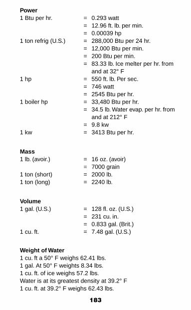
183
Power1 Btu per hr. = 0.293 watt = 12.96 ft. lb. per min. = 0.00039 hp1 ton refrig (U.S.) = 288,000 Btu per 24 hr. = 12,000 Btu per min. = 200 Btu per min. = 83.33 lb. Ice melter per hr. from and at 32° F1 hp = 550 ft. lb. Per sec. = 746 watt = 2545 Btu per hr.1 boiler hp = 33,480 Btu per hr. = 34.5 lb. Water evap. per hr. from and at 212° F = 9.8 kw1 kw = 3413 Btu per hr.
Mass1 lb. (avoir.) = 16 oz. (avoir) = 7000 grain1 ton (short) = 2000 lb.1 ton (long) = 2240 lb.
Volume1 gal. (U.S.) = 128 fl. oz. (U.S.) = 231 cu. in. = 0.833 gal. (Brit.)1 cu. ft. = 7.48 gal. (U.S.)
Weight of Water1 cu. ft a 50° F weighs 62.41 lbs.1 gal. At 50° F weights 8.34 lbs.1 cu. ft. of ice weighs 57.2 lbs.Water is at its greatest density at 39.2° F1 cu. ft. at 39.2° F weighs 62.43 lbs.

184
Conversion Constants
To Change To Multiply By
Inches Feet 0.0833
Inches Millimeters 25.4
Feet Inches 12
Feet Yards 0.3333
Yards Feet 3
Square inches Square feet 0.00694
Square feet Square inches 144
Square feet Square yards 0.11111
Square yards Square feet 9
Cubic inches Cubic feet 0.00058
Cubic feet Cubic inches 1728
Cubic feet Cubic yards 0.03703
Cubic yards Cubic feet 27
Cubic inches Gallons 0.00433
Cubic feet Gallons 7.48
Gallons Cubic inches 231
Gallons Cubic feet 0.1337
Gallons Pounds of water 8.33
Pounds of water Gallons 0.12004
Ounces Pounds 0.0625
Pounds Ounces 16
Inches of water Pounds/square inch 0.0361
Inches of water Inches of mercury 0.0735
Inches of water Ounces/square inch 0.578
Inches of water Pounds/square foot 5.2
Inches of mercury Inches of water 13.6
Inches of mercury Feet of water 1.1333

185
To Change To Multiply By
Inches of mercury Pounds/square inch 0.4914
Ounces/square inch Inches of mercury 0.127
Ounces/square inch Inches of water 1.733
Pounds/square inch Inches of water 27.72
Pounds/square inch Feet of water 2.310
Pounds/square inch Inches of mercury 2.04
Pounds/square inch Atmospheres 0.0681
Feet of water Pounds/square inch 0.434
Feet of water Pounds/square foot 62.5
Feet of water Inches of mercury 0.8824
Atmospheres Pounds/square inch 14.696
Atmospheres Inches of mercury 29.92
Atmospheres Feet of water 34
Long tons Pounds 2240
Short tons Pounds 2000
Short tons Long tons 0.89285
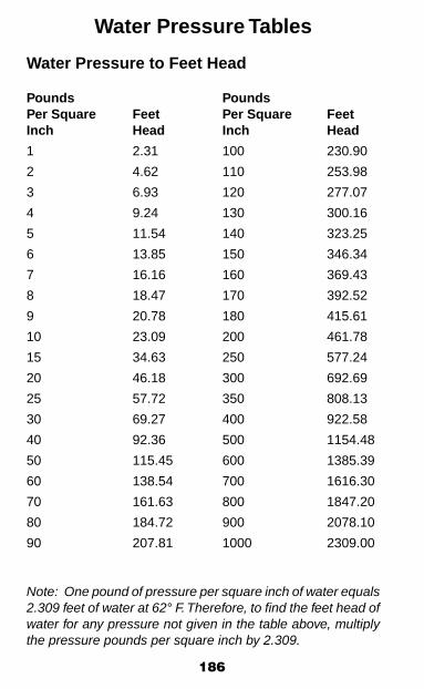
186
Water Pressure Tables
Water Pressure to Feet Head
Pounds PoundsPer Square Feet Per Square FeetInch Head Inch Head
1 2.31 100 230.90
2 4.62 110 253.98
3 6.93 120 277.07
4 9.24 130 300.16
5 11.54 140 323.25
6 13.85 150 346.34
7 16.16 160 369.43
8 18.47 170 392.52
9 20.78 180 415.61
10 23.09 200 461.78
15 34.63 250 577.24
20 46.18 300 692.69
25 57.72 350 808.13
30 69.27 400 922.58
40 92.36 500 1154.48
50 115.45 600 1385.39
60 138.54 700 1616.30
70 161.63 800 1847.20
80 184.72 900 2078.10
90 207.81 1000 2309.00
Note: One pound of pressure per square inch of water equals 2.309 feet of water at 62° F. Therefore, to find the feet head of water for any pressure not given in the table above, multiply the pressure pounds per square inch by 2.309.

187
Feet Head of Water to PSI
Pounds PoundsFeet Per Square Feet Per SquareHead Inch Head Inch
1 .43 100 43.31
2 .87 110 47.64
3 1.30 120 51.97
4 1.73 130 56.30
5 2.17 140 60.63
6 2.60 150 64.96
7 3.03 160 69.29
8 3.46 170 73.63
9 3.90 180 77.96
10 4.33 200 86.62
15 6.50 250 108.27
20 8.66 300 129.93
25 10.83 350 151.58
30 12.99 400 173.24
40 17.32 500 216.55
50 21.65 600 259.85
60 25.99 700 303.16
70 30.32 800 346.47
80 34.65 900 389.78
90 38.98 1000 433.00
Note: One foot of water at 62° F equals .433 pound pressure per square inch. To find the pressure per square inch for any feet head given in the table above, multiply the feet head by .433.
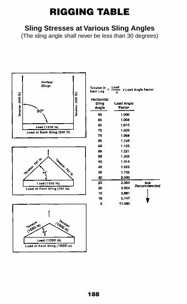
188
RIGGING TABLE
Sling Stresses at Various Sling Angles(The sling angle shall never be less than 30 degrees)
=
189
GlossaryACGIH: American Conference of Governmental Industrial Hygienist
ACWR: Area Civil Work Request
Affected Employee: An employee whose job requires him/her to operate or use a machine or equipment on which servicing or maintenance is being performed under lockout or tagout, or whose job requires him/her to work in an area in which such servicing or maintenance is being performed.
ANSI: American National Standards Institute
API: American Petroleum Institute
Appointed: Assigned specific responsibilities by the employer or the employer’s representative.
Approved: Approved for a specific purpose, environment, or application described in a particular Standard requirement. Suitability of equipment for a specific purpose may be deter-mined by a nationally recognized testing laboratory such as Underwriters or Factory Mutual.
Authorized: Appointed by a duly constituted administrative or regulatory authority. A person who is approved or assigned by the employer to perform a specific type of duty or duties or to be at a specific location or locations at the jobsite.
Authorized Employee: (for energy isolation purposes only): A person who locks out or tags out machines or equipment in order to perform servicing or maintenance on that machine or equipment. An affected employee becomes an authorized employee when that employee’s duties include performing servicing or maintenance covered under this section.
- Operator – The “Authorized Employee” in charge of the Energy Isolation. This includes shutting down, isolating, and locking out a piece of equipment for servicing or maintenance. This person will also be in charge of removing the equipment from lockout after the work is completed, and starting up the equipment.

190
- Worker – Anyone who applies a personal lock or tag to an energy isolation device, including a Lockbox, if used.
Auto ignition temperature: The temperature at which a substance will spontaneously combine with oxygen and burn without an external ignition or heat source.
Barricade: A structure set up across a route of access to obstruct the passage. Equipment used as barricading devices are: manhole covers, railings with toeboard, etc.
Blind: A device such as a metal plate, inserted into flanged joints, a blind flange or a cap or plug installed on the end of pipe lines used to prevent potentially hazardous or pressur-ized liquids, gases, or vapors from passing through a pipe line or nozzle.
CFR: Code of Federal Regulations
Classified Area: Facilities where hydrocarbons are handled, processed, or stored are classified according to specifications set forth in the NFPA, National Electric Code and API Recom-mended Practices.
You should know that an area classification extends 10 feet beyond the exterior wall or roof of a building, fan exhaust, vent, low point drain, high point vent or flanges.
From the National Electrical Code, 1993:
Class I, Division 1. A Class I, Division 1 is a location: (1) in which ignitable concentrations of flammable gases or vapors can exist under normal operating conditions; or (2) in which ignitable concentrations of such gases or vapors may exist frequently because of repair or maintenance operations or because of leakage; or (3) in which breakdown or faulty operation of equipment or processes might release ignitable concentrations of flammable gases or vapors, and might also cause simultaneous failure of electric equipment.
Class I, Division 2. A Class I, Division 2 is a location: (1) in which volatile flammable liquids or flammable gases are handled, processed, or used, but in which the liquids, vapors, or gases will normally be confined within closed containers or closed systems from which they can escape only in case of

191
accidental rupture or breakdown of such containers or systems, or in the case of abnormal operation of equipment; or (2) in which ignitable concentrations of gases or vapors are normally prevented by positive mechanical ventilation, and which might become hazardous through failure or abnormal operation of the ventilating equipment; or (3) that is adjacent to a Class I, Divi-sion 1 location, and to which ignitable concentrations of gases or vapors might occasionally be communicated unless such communication is prevented by adequate positive-pressure ventilation from a source of clean air, and effective safeguards against ventilation failure are provided.
Cold Cutting: The cutting of any line with a Wachs saw, powered hacksaw, or any other device which is non-sparking.
Cold Tapping: The drilling of a line or equipment after it has been depressured, blocked, and opened to atmosphere.
Combustible Fluids: Fluids with a flash point at or above 100° F.
Competent Person: A person who is capable of identifying existing and predictable hazards in the surroundings or working conditions, which are unsanitary, hazardous, or dangerous to employees, and who has authorization to take prompt correc-tive measures to eliminate them.
Copy of Record: The copy of safe work permits that the Company requires to be filed for a specified period of time.
Control Locks: These are keyed-alike locks that are used to protect the process or equipment, but not for personal protection.
Designated Worker: A worker who has taken on the additional responsibility to protect the safety of other workers by allowing them to work under the protection of his/her Personal Lock.
Designee: A person who has been delegated by a higher authority to complete a specific task. Note: When work is accomplished under the provision of a delegated authority (a designee), the individual delegating the authority remains ultimately responsible. Also, designees shall sign for the del-egating authority as in the following example: John Doe for Jane Smith.
192
Device Lock: A Uniquely Keyed lock(s) where the key is under the exclusive control of the Lockbox. This lock is applied directly to the Energy Isolation Device only when a Lock Box Lock Out technique is being used. Device Locks that are assigned for use with a Lockbox shall have a EI Tag attached.
Direct-fired Heaters: Open flame contained within a por-table device with a fuel source used for heating. This includes salamanders, blow torches, natural gas and LP gas heaters.
EIL: Energy Isolation List
Energized Electrical Work Permit: If live parts are not placed in an electrically safe work condition (i.e. for the reason of increased or additional hazards or infeasibility), work to be performed shall be considered energized electrical work and shall be performed by written permit only.
Energy Isolation: The method(s) for physically preventing the transmission of an Energy Source into an area where work is being performed. This is done using Energy Isolation Devices.
Energy Isolation Device: A mechanical device that physically prevents the transmission of an Energy Source. Note: Push buttons, selector switches, and other control circuit type devices that do not directly control the electricity ARE NOT Energy Isolation Devices.
Energy Isolation List: A form used to identify and record all devices used to isolate potential sources of energy prior to servicing or performing maintenance on any equipment or machinery.
Energy Source: Any source of energy. Examples include electrical, pressure, mechanical, gravity, heat/cold. Radiation, biological, and chemical (corrosives, etc).
Equipment: Piping systems and mechanical equipment that require maintenance, or servicing, and have the potential to contain an Energy Source.
Exclusive Control: The Energy Isolation Device is within a worker’s arm’s reach and within their line of sight while they are working, OR is locked with the worker’s Personal Lock.
193
Fall Restraint System: An approved device and any neces-sary components that function together to restrain an employee in such a manner as to prevent that employee from reaching the edge and falling.
Fire Zone: An enclosed area covered by one zone of a fire or gas detection system.
Flammable Fluids: Fluids with a flash point below 100° F.
Flash Point: The minimum temperature at which a liquid gives off vapor in sufficient concentration to form an ignitable mixture with air near the surface of the liquid within the vessel as specified by appropriate test procedure and apparatus.
GPB: Greater Prudhoe Bay
Group: Two or more workers working under the protection of one of the worker’s (Designated Worker) Personal Lock(s).
Hot Tapping: A method of adding a branch connection to a pressurized line without removing the line from service. The hot tapping procedure includes the attachment weld, hydrostatic test, and drilling of the pipe or other equipment.
Indirect-fired Heaters: A contained fired heated medium, normally fan assisted, used for area heating. This includes kerosene heaters, catalytic heaters, and boilers.
Intrinsically Safe: A condition in which any spark or thermal effect is incapable of causing ignition of a mixture of flammable or combustible material in air.
Isolation Procedures: Isolation procedures contain instruc-tions for isolating all forms of energy associated with equip-ment for the protection of personnel during servicing and maintenance procedures.
LEL: Lower Explosive Limit
Lockbox: A box with the ability to be locked closed so that the contents inside the box cannot be removed without first removing a lock(s).

194
Lockout: The placement of a lock on an energy isolating device to ensure the energy source and equipment being controlled cannot be operated. Locks used must also positively identify their user.
Lockout Device: A mechanism which provides a positive means of control and accommodates multiple locks.
Master Card: An envelope used to log information, retain stubs from all two-part tags associated with locks and tags, and provide the most current status of process and other equip-ment that has been secured. It is an envelope with an Energy Isolation List printed on one side and Worker Log form printed on the other. It is always maintained in a location central to the process or equipment under control. A separate Master Card or EIL shall be completed for each job.
Means of Egress: A continuous and unobstructed way of exit travel from any point in a building or structure to a public way. Means of egress consist of three parts: the way of exit access, the exit, and the way of exit discharge.
NGL: Natural Gas Liquids
NEC: National Electrical Code (NFPA70) covers installation requirements.
NFPA70E: Standard for Electrical Safety in the Workplace addresses safe work practices and employee protection.
NFPA: National Fire Protection Association
Non-permanent Facilities: Temporary structures such as storage or break shacks and other mobile equipment includ-ing vacuum trucks, tanker trucks, and other mobile/temporary equipment or holding tanks.
On-line Plugging: On-line plugging includes operations to stop flow in existing process equipment and/or piping. For example, placing an in-line stopple.
Personal Lock: A Uniquely Keyed lock(s) where the key is under the exclusive control of one worker. These locks are painted red and are clearly labeled with the employee’s name and contact number. The purpose of a Personal Lock is to protect the worker from injury due to the accidental release of energy.

195
Pyrophoric: The ability to spontaneously ignite in the pres-ence of air.
Qualified: A person who, by possession of a recognized degree, certificate, or professional standing, or who by exten-sive knowledge, training and experience, has successfully demonstrated the ability to solve or resolve problems relating to the subject matter, the work, or the project and is competent to judge the hazards involved.
Safety Device: Any operational device that safely controls the release of pressure, temperature, liquid levels, flow, etc., or protects the integrity of the equipment, preventing cata-strophic failures.
Shift: For the purpose of Safety Handbook, the term “shift” refers to a daily work period of 8 hours or 12 hours, depending on the specific Company work location.
Simultaneous Operations (SIMOPS): The existence of multiple work processes in a single work area. These work processes may not be interrelated but are viewed as having the potential to introduce additional risk into an operation un-less properly managed.
Tagout Device(s): A prominent means of warning and its at-tachment device, which must be substantial enough to prevent inadvertent or accidental removal. Tagout devices must be non-reusable, attached by hand, self-locking, and capable of withstanding no less than 50 lbs. pull.
THA: Task Hazard Assessment
Trained: Knowledgeable in a specific subject material through lectures, testing, and hands-on activities. Results documented.
UL: Underwriter’s Laboratory
Welding, Burning/Cutting, Grinding: The process of melting or removing metal for the purpose of fabrication or repair (eg. arc welding, gas welding, torch cutting by burning or disk grinding).
Worker Log: A form used to record all individuals working under energy isolation.
Zero Energy State: A condition in which all potential sources of energy are eliminated.

196
IndexAircraft, Fixed Wing, 48, 49Alaska Safety Handbook Amendment Form, 200Alaska Safety Handbook Amendment Procedure, 199Amber Rotating Beacon, 152Area Civil Work Request (ACWR) Form, 140-142, 189Asbestos, 8, 159Audiometric Testing, 16Barricades, 10, 25, 26, 112, 145Blinding (See Process Opening/Blinding), 78, 122Boats, 51, 52Bonding, Grounding, 22, 41, 110, 125, 166, 168, 177Cam & Groove Fittings, 29Caution Tag, 130, 134Cell Phone, 5, 45Classified Areas, 5, 30, 31, 63, 72, 73, 161 147, 158, 161, 175, 190Clothing, 6, 16, 45, 49, 50, 77Cold Related Injuries, 17Compressed Air, 6, 40, 112Compressed Gas Cylinders, 38, 40Confined Space Entry, 66-68, 84, 86- 88, 91- 98, 126, 146Confined Space Entry Permit, 81, 82, 83Contact Lenses, 14Contractors, 1, 4, 35, 86, 101, 103Cranes, 32-36, 49, 72-73Danger Tag, 133, 135, 137Defeated Safety Devices, 137, 138Do Not Enter Tag, 87, 89, 91, 162Double Block & Bleed, 79, 87, 110, 112, 125-126Drilling, 21, 35, 37, 42, 46, 54, 58, 59, 64, 101, 112, 122, 140, 142, 159, 191, 193Drivers License, 43-46Energy Isolation Standard, 25, 57, 67-68, 85, 87, 91-94, 101-117, 122-123, 133-135, 143, 192Energy Isolation Tag, 103, 104, 105, 108, 110, 111, 113, 118, 192Escort, 46, 152, 153, 157Evacuation, 9, 10, 13, 56, 95, 156, 157Excavating, 142Eye Protection, 14, 43Fall Protection, 19, 28, 31, 112
197
Fire Extinguishers, 6, 10, 11, 40, 74, 161Fire Protection, 10, 11, 18, 194Fire Watch, 73, 75, 77Fired Heater, 25, 125, 173-176, 192-193Flagging, 104, 133, 134Flame Retardant Clothing (FRC), 16Flammable and Combustible, 10-12, 18, 24, 41, 63, 72, 165-168, 173-176Foam, 12Foot Protection, 15Foul Weather Contingency Plan, 47Frostbite, 17, 18Ground Fault Circuit Interrupters (GFCI), 22Halon, 12, 138, 139Hard Hats, 15Hazard Communication Program, 8, 111Headlights, 43, 45Hearing Protection, 16, 22, 50Heaters, 11, 25, 63-64, 72, 85, 112, 125, 173-176, 192-193Heavy Equipment, 32, 43, 45, 47, 150Helicopters, 49Hot Tapping, 63, 66, 163, 164, 193Hot Work in Confined Space, 79Hot Work Permit, 22, 72-80, 86, 88, 97, 147, 161-163, 175Hydrogen Sulfide Standard (H
2S), 155Hydrostatic Testing, 65, 67, 169Hypothermia, 17Impedance Pipe Thaw Standard, 161Industrial Hygiene Program, 8Iron Sulfide, 158Ladders, 15, 24, 27, 28, 31Lockbox Lockout Flow Chart, 118Locks, Lockout, 57, 101-103, 106, 108, 110-113, 115-119, 134, 185, 187-190-194Low Temperature Operations, 35Material Safety Data Sheets (MSDS), 8, 14, 41, 111Module Movement, 154Naturally Occurring Radioactive Material (norm), 8, 98, 111Neoprene Module Interconnects, 79, 176

198
Natural Gas Liquids (NGL), 25, 194Non Explosion-proof Lighting, 22Office and Camp Safety, 9Offshore, 33, 49, 51Orientation, 2, 9, 157Process Opening/Blinding Standard, 64, 79, 122Process Safety Management (PSM), 9Radio Checks, 45, 46, 48, 59, 126Respiratory Protection, 8, 14-15, 73, 80, 123, 157Retrieval Systems, 88Rigging, 31, 33-35, 37, 188Safe to Enter With Restrictions Tag, 87, 90-92Safety Glasses, 14, 22, 41, 43, 49Safety Meetings, 2, 3Safety Standard Variance, 178-179Safety Surveys, 2Scaffolds, 30-31Seatbelts, 32, 43Secondary Containers, 41Sheet Metal Storage, 30Simultaneous Operations (SIMOPS), 55, 195Smoking, 21, 40Snow Removal, 32, 36, 63, 72, 142, 147-150Spills, 10, 18, 26,168Sprinkler Heads, 10, 12, 30Steam, 24-26, 30, 87, 112, 158 Storage, 10, 22, 28, 30, 38, 40, 194Structural Penetration Standard, 159Tagging & Flagging Standard, 133Titles, 53Toe Boards, 19Tools, 6, 22, 28-29, 40, 72, 108, 111-112, 122Trenching, 142Unit Work Standard, 63, 84,-85Variance to Safety Standard, 178-179Vehicle Accidents, 43-44Ventilation, 73, 80, 88, 91, 94, 97, 123, 158, 191Welding, 14, 35, 72-74, 77-80, 111-112, 171, 195Well Work, 58-59, 63-64, 122-123

199
Alaska Safety Handbook Amendment Procedure
There is a standing committee comprised of representatives of each company that will meet semi-annually to review proposed changes.
If you believe that an amendment to this Safety Handbook would be appropriate, please submit a brief proposal to Company Safety Department explaining the nature of the suggested addition, revision, or deletion.

200
Alaska Safety Handbook Amendment Form
Name Ext.
Work Location
Page(s) to be Changed
Suggested Change:
Reason for Change:
Return to Company Safety Department