0-10V AHU DX Coil Interface Specification (R04 28 -01 20 ... · 0-10V AHU DX Coil Interface...
19
1 0-10V AHU DX Coil Interface Specification (R04 28-01-2020) 1 Application The new 0-10V AHU DX Coil Interface enables BMS capacity demand control of Toshiba Outdoor units connected to a DX Coil (with a field supplied AHU). It is compatible with Toshiba R410A LC outdoor units (DI /SDI / DI-Big), Toshiba R32 LC outdoor units (DI / SDI) or a Toshiba R410A VRF outdoor units (SMMSi / SMMSe). Toshiba LC systems only require the DX Controller, Toshiba VRF systems additionally require a suitably sized VRF DX PMV:- RBC-DXC031 LC / VRF DX CONTROLLER (0-10V AHU) MM-DXV141 VRF DX PMV (16.0kW) [6.0HP] MM-DXV281 VRF DX PMV (22.4kW, 28.0kW) [8.0HP / 10.0HP] 2 System compatibility Outdoor Unit Model HP VRF SMMSi /SMMSe Outdoor Units [75% - 100% Diversity] MMY-MAP0804HT8P-E / MAP0806HT8P-E MMY-MAP0804HT8JP-E / MAP0806HT8JP-E MMY-MAP0804HT8P-ME / MAP0806HT8P-ME MMY-MAP0804HT8P-TR / MAP0806HT8P-TR MMY-MAP0804HT8JP-TR / MAP0806HT8JP-TR 8 [6, 8] MMY-MAP1004HT8P-E / MAP1006HT8P-E MMY-MAP1004HT8JP-E / MAP1006HT8JP-E MMY-MAP1004HT8P-ME / MAP1006HT8P-ME MMY-MAP1004HT8P-TR / MAP1006HT8P-TR MMY-MAP1004HT8JP-TR / MAP1006HT8JP-TR 10 [8, 10] LC DI Outdoor Units (R410A) RAV-SM304ATP-E 1.0 RAV-SM404ATP-E 1.5 RAV-SM564ATP-E 2.0 RAV-SM804ATP-E 3.0 RAV-SM1104ATP-E 4.0 RAV-SM1404ATP-E 5.0 RAV-SM1603AT-E 6.0 LC DI-Big Outdoor Units (R410A) RAV-SM2224AT8-E 8.0 RAV-SM2804AT8-E 10.0 LC SDI Outdoor Units (R410A) RAV-SP404TP-E 1.5 RAV-SP564ATP-E 2.0 RAV-SP804ATP-E 3.0 RAV-SP1104AT-E 4.0 RAV-SP1104AT8-E 4.0 RAV-SP1404AT-E 5.0 RAV-SP1404AT8-E 5.0 RAV-SP1604AT8-E 6.0 LC DI Outdoor Units (R32) RAV-SM301ATP-E 1.0 RAV-GM401ATP-E 1.5 RAV-GM561ATP-E 2.0 RAV-GM801ATP-E 3.0 RAV-GM1101ATP-E 4.0 RAV-GM1401ATP-E 5.0 RAV-GM1101AT8P-E 4.0 RAV-GM1401AT8P-E 5.0 LC SDI Outdoor Units (R32) RAV-GP561ATP-E 2.0 RAV-GP801AT-E 3.0 RAV-GP1101AT-E 4.0 RAV-GP1401AT-E 5.0
Transcript of 0-10V AHU DX Coil Interface Specification (R04 28 -01 20 ... · 0-10V AHU DX Coil Interface...
1
0-10V AHU DX Coil Interface Specification (R04 28-01-2020)
1 Application
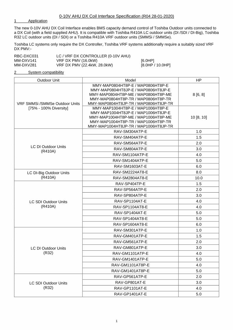
The new 0-10V AHU DX Coil Interface enables BMS capacity demand control of Toshiba Outdoor units connected to a DX Coil (with a field supplied AHU). It is compatible with Toshiba R410A LC outdoor units (DI /SDI / DI-Big), Toshiba R32 LC outdoor units (DI / SDI) or a Toshiba R410A VRF outdoor units (SMMSi / SMMSe).
Toshiba LC systems only require the DX Controller, Toshiba VRF systems additionally require a suitably sized VRF DX PMV:-
RBC-DXC031 LC / VRF DX CONTROLLER (0-10V AHU) MM-DXV141 VRF DX PMV (16.0kW) [6.0HP] MM-DXV281 VRF DX PMV (22.4kW, 28.0kW) [8.0HP / 10.0HP]
2 System compatibility
Outdoor Unit Model HP
VRF SMMSi /SMMSe Outdoor Units [75% - 100% Diversity]
MMY-MAP0804HT8P-E / MAP0806HT8P-E MMY-MAP0804HT8JP-E / MAP0806HT8JP-E
MMY-MAP0804HT8P-ME / MAP0806HT8P-ME MMY-MAP0804HT8P-TR / MAP0806HT8P-TR
MMY-MAP0804HT8JP-TR / MAP0806HT8JP-TR
8 [6, 8]
MMY-MAP1004HT8P-E / MAP1006HT8P-E MMY-MAP1004HT8JP-E / MAP1006HT8JP-E
MMY-MAP1004HT8P-ME / MAP1006HT8P-ME MMY-MAP1004HT8P-TR / MAP1006HT8P-TR
MMY-MAP1004HT8JP-TR / MAP1006HT8JP-TR
10 [8, 10]
LC DI Outdoor Units (R410A)
RAV-SM304ATP-E 1.0
RAV-SM404ATP-E 1.5
RAV-SM564ATP-E 2.0
RAV-SM804ATP-E 3.0
RAV-SM1104ATP-E 4.0
RAV-SM1404ATP-E 5.0
RAV-SM1603AT-E 6.0
LC DI-Big Outdoor Units (R410A)
RAV-SM2224AT8-E 8.0
RAV-SM2804AT8-E 10.0
LC SDI Outdoor Units (R410A)
RAV-SP404TP-E 1.5
RAV-SP564ATP-E 2.0
RAV-SP804ATP-E 3.0
RAV-SP1104AT-E 4.0
RAV-SP1104AT8-E 4.0
RAV-SP1404AT-E 5.0
RAV-SP1404AT8-E 5.0
RAV-SP1604AT8-E 6.0
LC DI Outdoor Units (R32)
RAV-SM301ATP-E 1.0
RAV-GM401ATP-E 1.5
RAV-GM561ATP-E 2.0
RAV-GM801ATP-E 3.0
RAV-GM1101ATP-E 4.0
RAV-GM1401ATP-E 5.0
RAV-GM1101AT8P-E 4.0
RAV-GM1401AT8P-E 5.0
LC SDI Outdoor Units (R32)
RAV-GP561ATP-E 2.0
RAV-GP801AT-E 3.0
RAV-GP1101AT-E 4.0
RAV-GP1401AT-E 5.0
2
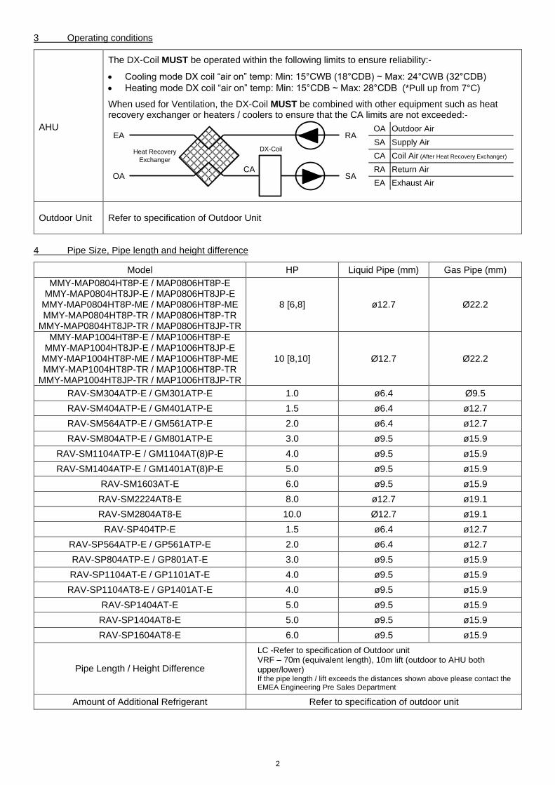
3 Operating conditions
AHU
The DX-Coil MUST be operated within the following limits to ensure reliability:-
Cooling mode DX coil “air on” temp: Min: 15°CWB (18°CDB) ~ Max: 24°CWB (32°CDB)
Heating mode DX coil “air on” temp: Min: 15°CDB ~ Max: 28°CDB (*Pull up from 7°C)
When used for Ventilation, the DX-Coil MUST be combined with other equipment such as heat recovery exchanger or heaters / coolers to ensure that the CA limits are not exceeded:-
Outdoor Unit Refer to specification of Outdoor Unit
4 Pipe Size, Pipe length and height difference
Model HP Liquid Pipe (mm) Gas Pipe (mm)
MMY-MAP0804HT8P-E / MAP0806HT8P-E MMY-MAP0804HT8JP-E / MAP0806HT8JP-E
MMY-MAP0804HT8P-ME / MAP0806HT8P-ME MMY-MAP0804HT8P-TR / MAP0806HT8P-TR
MMY-MAP0804HT8JP-TR / MAP0806HT8JP-TR
8 [6,8] ø12.7 Ø22.2
MMY-MAP1004HT8P-E / MAP1006HT8P-E MMY-MAP1004HT8JP-E / MAP1006HT8JP-E
MMY-MAP1004HT8P-ME / MAP1006HT8P-ME MMY-MAP1004HT8P-TR / MAP1006HT8P-TR
MMY-MAP1004HT8JP-TR / MAP1006HT8JP-TR
10 [8,10] Ø12.7 Ø22.2
RAV-SM304ATP-E / GM301ATP-E 1.0 ø6.4 Ø9.5
RAV-SM404ATP-E / GM401ATP-E 1.5 ø6.4 ø12.7
RAV-SM564ATP-E / GM561ATP-E 2.0 ø6.4 ø12.7
RAV-SM804ATP-E / GM801ATP-E 3.0 ø9.5 ø15.9
RAV-SM1104ATP-E / GM1104AT(8)P-E 4.0 ø9.5 ø15.9
RAV-SM1404ATP-E / GM1401AT(8)P-E 5.0 ø9.5 ø15.9
RAV-SM1603AT-E 6.0 ø9.5 ø15.9
RAV-SM2224AT8-E 8.0 ø12.7 ø19.1
RAV-SM2804AT8-E 10.0 Ø12.7 ø19.1
RAV-SP404TP-E 1.5 ø6.4 ø12.7
RAV-SP564ATP-E / GP561ATP-E 2.0 ø6.4 ø12.7
RAV-SP804ATP-E / GP801AT-E 3.0 ø9.5 ø15.9
RAV-SP1104AT-E / GP1101AT-E 4.0 ø9.5 ø15.9
RAV-SP1104AT8-E / GP1401AT-E 4.0 ø9.5 ø15.9
RAV-SP1404AT-E 5.0 ø9.5 ø15.9
RAV-SP1404AT8-E 5.0 ø9.5 ø15.9
RAV-SP1604AT8-E 6.0 ø9.5 ø15.9
Pipe Length / Height Difference
LC -Refer to specification of Outdoor unit VRF – 70m (equivalent length), 10m lift (outdoor to AHU both upper/lower) If the pipe length / lift exceeds the distances shown above please contact the EMEA Engineering Pre Sales Department
Amount of Additional Refrigerant Refer to specification of outdoor unit
RA Return Air
EA Exhaust Air
OA Outdoor Air
SA Supply Air
CA Coil Air (After Heat Recovery Exchanger)
RA
SAOA
EA
CA
Heat Recovery
Exchanger
DX-Coil
3
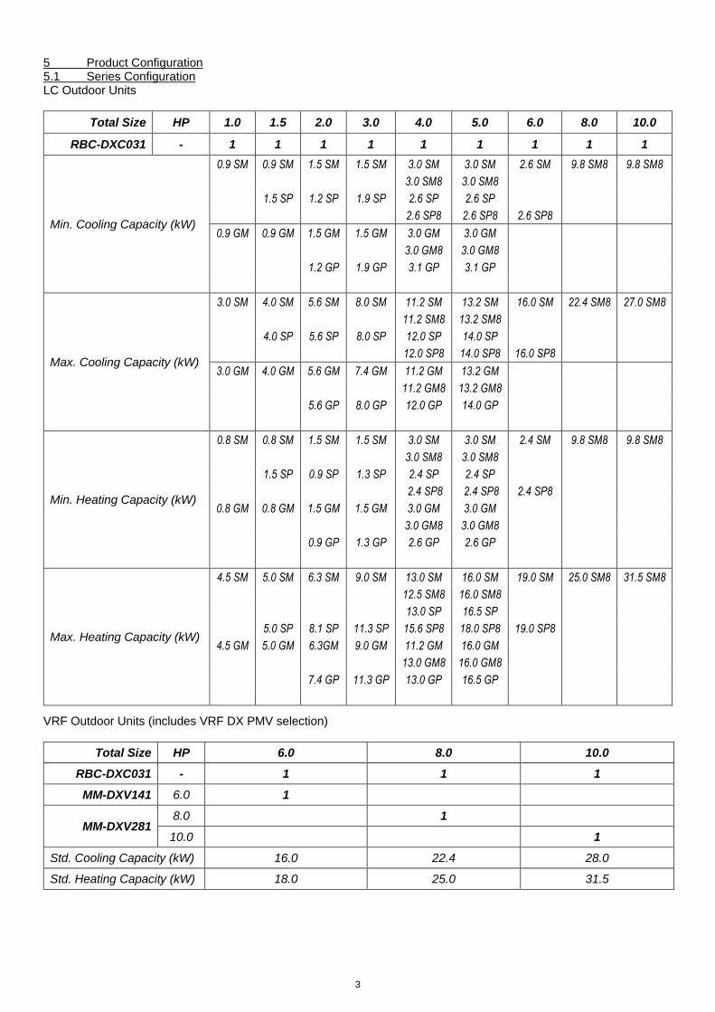
5 Product Configuration 5.1 Series Configuration LC Outdoor Units
Total Size HP 1.0 1.5 2.0 3.0 4.0 5.0 6.0 8.0 10.0
RBC-DXC031 - 1 1 1 1 1 1 1 1 1
Min. Cooling Capacity (kW)
0.9 SM 0.9 SM 1.5 SM 1.5 SM 3.0 SM 3.0 SM 2.6 SM 9.8 SM8 9.8 SM8
3.0 SM8 3.0 SM8
1.5 SP 1.2 SP 1.9 SP 2.6 SP 2.6 SP
2.6 SP8 2.6 SP8 2.6 SP8
0.9 GM 0.9 GM 1.5 GM 1.5 GM 3.0 GM 3.0 GM
3.0 GM8 3.0 GM8
1.2 GP 1.9 GP 3.1 GP 3.1 GP
Max. Cooling Capacity (kW)
3.0 SM 4.0 SM 5.6 SM 8.0 SM 11.2 SM 13.2 SM 16.0 SM 22.4 SM8 27.0 SM8
11.2 SM8 13.2 SM8
4.0 SP 5.6 SP 8.0 SP 12.0 SP 14.0 SP
12.0 SP8 14.0 SP8 16.0 SP8
3.0 GM 4.0 GM 5.6 GM 7.4 GM 11.2 GM 13.2 GM
11.2 GM8 13.2 GM8
5.6 GP 8.0 GP 12.0 GP 14.0 GP
Min. Heating Capacity (kW)
0.8 SM 0.8 SM 1.5 SM 1.5 SM 3.0 SM 3.0 SM 2.4 SM 9.8 SM8 9.8 SM8
3.0 SM8 3.0 SM8
1.5 SP 0.9 SP 1.3 SP 2.4 SP 2.4 SP
2.4 SP8 2.4 SP8 2.4 SP8
0.8 GM 0.8 GM 1.5 GM 1.5 GM 3.0 GM 3.0 GM
3.0 GM8 3.0 GM8
0.9 GP 1.3 GP 2.6 GP 2.6 GP
Max. Heating Capacity (kW)
4.5 SM 5.0 SM 6.3 SM 9.0 SM 13.0 SM 16.0 SM 19.0 SM 25.0 SM8 31.5 SM8
12.5 SM8 16.0 SM8
13.0 SP 16.5 SP
5.0 SP 8.1 SP 11.3 SP 15.6 SP8 18.0 SP8 19.0 SP8
4.5 GM 5.0 GM 6.3GM 9.0 GM 11.2 GM 16.0 GM
13.0 GM8 16.0 GM8
7.4 GP 11.3 GP 13.0 GP 16.5 GP
VRF Outdoor Units (includes VRF DX PMV selection)
Total Size HP 6.0 8.0 10.0
RBC-DXC031 - 1 1 1
MM-DXV141 6.0 1
MM-DXV281 8.0 1
10.0 1
Std. Cooling Capacity (kW) 16.0 22.4 28.0
Std. Heating Capacity (kW) 18.0 25.0 31.5
4
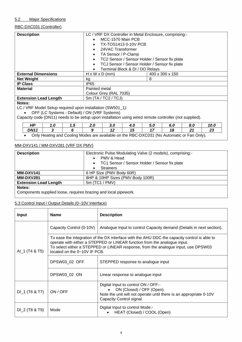
5.2 Major Specifications
RBC-DXC031 (Controller)
Description LC / VRF DX Controller in Metal Enclosure, comprising:- MCC-1570 Main PCB
TX-TOS1413 0-10V PCB
24VAC Transformer
TA Sensor / P-Clamp
TC2 Sensor / Sensor Holder / Sensor fix plate
TCJ Sensor / Sensor Holder / Sensor fix plate
Terminal Block & DI / DO Relays
External Dimensions H x W x D (mm) 400 x 300 x 150
Net Weight kg 8
IP Class IP65
Material Painted metal Colour Grey (RAL 7035)
Extension Lead Length 5m (TA / TC2 / TCJ)
Notes: LC / VRF Model Setup required upon installation (SW501_1):
OFF (LC Systems - Default) / ON (VRF Systems) Capacity code (DN11) needs to be setup upon installation using wired remote controller (not supplied).
Only Heating and Cooling Modes are available on the RBC-DXC031 (No Automatic or Fan Only).
HP 1.0 1.5 2.0 3.0 4.0 5.0 6.0 8.0 10.0
DN11 3 6 9 12 15 17 18 21 23
MM-DXV141 / MM-DXV281 (VRF DX PMV)
Description Electronic Pulse Modulating Valve (2 models), comprising:-
PMV & Head
TC1 Sensor / Sensor Holder / Sensor fix plate
Strainers
MM-DXV141 6 HP Size (PMV Body 60R)
MM-DXV281 8HP & 10HP Sizes (PMV Body 100R)
Extension Lead Length 5m (TC1 / PMV)
Notes: Components supplied loose, requires brazing and local pipework.
5.3 Control Input / Output Details (0~10V Interface)
Input Name Description
AI_1 (T4 & T5)
Capacity Control (0-10V) Analogue Input to control Capacity demand (Details in next section).
To ease the integration of the DX interface with the AHU DDC the capacity control is able to operate with either a STEPPED or LINEAR function from the analogue input. To select either a STEPPED or LINEAR response, from the analogue input, use DPSW03 located on the 0~10V IF PCB.
DPSW03_02 OFF STEPPED response to analogue input
DPSW03_02 ON Linear response to analogue input
DI_1 (T6 & T7) ON / OFF
Digital Input to control ON / OFF:-
ON (Closed) / OFF (Open). Note the unit will not operate until there is an appropriate 0-10V Capacity Control signal.
DI_2 (T8 & T9) Mode Digital Input to control Mode:-
HEAT (Closed) / COOL (Open)
5
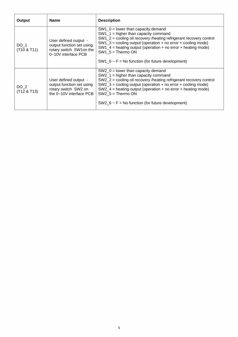
Output Name Description
DO_1 (T10 & T11)
User defined output - output function set using rotary switch SW1on the 0~10V interface PCB
SW1_0 = lower than capacity demand SW1_1 = higher than capacity command SW1_2 = cooling oil recovery /heating refrigerant recovery control SW1_3 = cooling output (operation + no error + cooling mode) SW1_4 = heating output (operation + no error + heating mode) SW1_5 = Thermo ON SW1_6 ~ F = No function (for future development)
DO_2 (T12 & T13)
User defined output - output function set using rotary switch SW2 on the 0~10V interface PCB
SW2_0 = lower than capacity demand SW2_1 = higher than capacity command SW2_2 = cooling oil recovery /heating refrigerant recovery control SW2_3 = cooling output (operation + no error + cooling mode) SW2_4 = heating output (operation + no error + heating mode) SW2_5 = Thermo ON SW2_6 ~ F = No function (for future development)
6
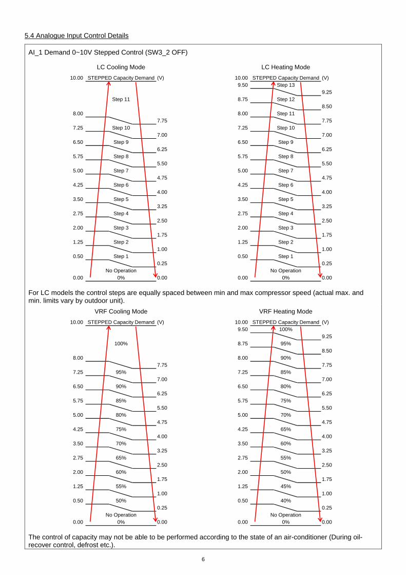
5.4 Analogue Input Control Details
AI_1 Demand 0~10V Stepped Control (SW3_2 OFF)
For LC models the control steps are equally spaced between min and max compressor speed (actual max. and min. limits vary by outdoor unit).
The control of capacity may not be able to be performed according to the state of an air-conditioner (During oil-recover control, defrost etc.).
10.00 STEPPED Capacity Demand (V) 10.00 STEPPED Capacity Demand (V)
9.50 Step 13
9.25
Step 11 8.75 Step 12
8.50
8.00 8.00 Step 11
7.75 7.75
7.25 Step 10 7.25 Step 10
7.00 7.00
6.50 Step 9 6.50 Step 9
6.25 6.25
5.75 Step 8 5.75 Step 8
5.50 5.50
5.00 Step 7 5.00 Step 7
4.75 4.75
4.25 Step 6 4.25 Step 6
4.00 4.00
3.50 Step 5 3.50 Step 5
3.25 3.25
2.75 Step 4 2.75 Step 4
2.50 2.50
2.00 Step 3 2.00 Step 3
1.75 1.75
1.25 Step 2 1.25 Step 2
1.00 1.00
0.50 Step 1 0.50 Step 1
0.25 0.25
No Operation No Operation
0.00 0% 0.00 0.00 0% 0.00
LC Cooling Mode LC Heating Mode
10.00 STEPPED Capacity Demand (V) 10.00 STEPPED Capacity Demand (V)
9.50 100%
9.25
100% 8.75 95%
8.50
8.00 8.00 90%
7.75 7.75
7.25 95% 7.25 85%
7.00 7.00
6.50 90% 6.50 80%
6.25 6.25
5.75 85% 5.75 75%
5.50 5.50
5.00 80% 5.00 70%
4.75 4.75
4.25 75% 4.25 65%
4.00 4.00
3.50 70% 3.50 60%
3.25 3.25
2.75 65% 2.75 55%
2.50 2.50
2.00 60% 2.00 50%
1.75 1.75
1.25 55% 1.25 45%
1.00 1.00
0.50 50% 0.50 40%
0.25 0.25
No Operation No Operation
0.00 0% 0.00 0.00 0% 0.00
VRF Cooling Mode VRF Heating Mode
7
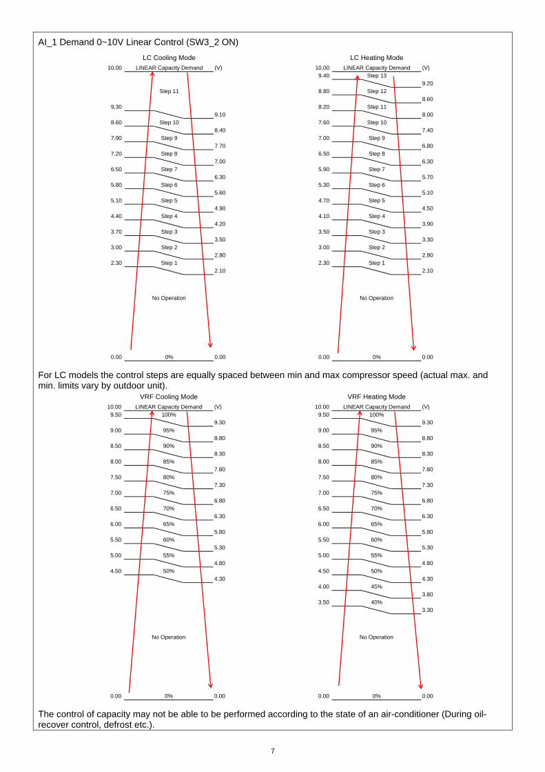
AI_1 Demand 0~10V Linear Control (SW3_2 ON)
For LC models the control steps are equally spaced between min and max compressor speed (actual max. and min. limits vary by outdoor unit).
The control of capacity may not be able to be performed according to the state of an air-conditioner (During oil-recover control, defrost etc.).
10.00 LINEAR Capacity Demand (V) 10.00 LINEAR Capacity Demand (V)
9.40 Step 13
9.20
Step 11 8.80 Step 12
8.60
9.30 8.20 Step 11
9.10 8.00
8.60 Step 10 7.60 Step 10
8.40 7.40
7.90 Step 9 7.00 Step 9
7.70 6.80
7.20 Step 8 6.50 Step 8
7.00 6.30
6.50 Step 7 5.90 Step 7
6.30 5.70
5.80 Step 6 5.30 Step 6
5.60 5.10
5.10 Step 5 4.70 Step 5
4.90 4.50
4.40 Step 4 4.10 Step 4
4.20 3.90
3.70 Step 3 3.50 Step 3
3.50 3.30
3.00 Step 2 3.00 Step 2
2.80 2.80
2.30 Step 1 2.30 Step 1
2.10 2.10
0.00 0% 0.00 0.00 0% 0.00
LC Cooling Mode LC Heating Mode
No Operation No Operation
10.00 LINEAR Capacity Demand (V) 10.00 LINEAR Capacity Demand (V)
9.50 100% 9.50 100%
9.30 9.30
9.00 95% 9.00 95%
8.80 8.80
8.50 90% 8.50 90%
8.30 8.30
8.00 85% 8.00 85%
7.80 7.80
7.50 80% 7.50 80%
7.30 7.30
7.00 75% 7.00 75%
6.80 6.80
6.50 70% 6.50 70%
6.30 6.30
6.00 65% 6.00 65%
5.80 5.80
5.50 60% 5.50 60%
5.30 5.30
5.00 55% 5.00 55%
4.80 4.80
4.50 50% 4.50 50%
4.30 4.30
4.00 45%
3.80
3.50 40%
3.30
0.00 0% 0.00 0.00 0% 0.00
VRF Cooling Mode VRF Heating Mode
No Operation No Operation
8
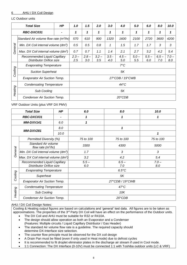
6 AHU / DX Coil Design
LC Outdoor units
Total Size HP 1.0 1.5 2.0 3.0 4.0 5.0 6.0 8.0 10.0
RBC-DXC031 - 1 1 1 1 1 1 1 1 1
Ge
ne
ral
Standard Air volume flow rate (m3/hr) 570 610 900 1320 1600 2100 2720 3600 4200
Min. DX Coil internal volume (dm3) 0.5 0.5 0.8 1 1.5 1.7 1.7 3 3
Max. DX Coil internal volume (dm3) 0.7 0.7 1.1 1.4 2.1 2.7 3.2 4.2 5.4
Recommended Liquid Capillary Distributor Orifice size
2.3 – 2.5
2.8 – 3.0
3.2 – 3.5
3.5 - 4.0
4.5 – 5.0
5.0 – 5.5
5.5 – 6.0
6.5 – 7.0
7.0 – 8.0
Co
olin
g Evaporating Temperature 7°C
Suction Superheat 5K
Evaporator Air Suction Temp. 27°CDB / 19°CWB
He
ating Condensating Temperature 44°C
Sub Cooling 5K
Condenser Air Suction Temp. 20°CDB
VRF Outdoor Units (plus VRF DX PMV)
Total Size HP 6.0 8.0 10.0
RBC-DXC031 - 1 1 1
MM-DXV141 6.0 1
MM-DXV281 8.0 1
10.0 1
Ge
ne
ral
Permitted Diversity (%) 75 to 100 75 to 100 75 to 100
Standard Air volume flow rate (m3/hr)
3300 4300 5000
Min. DX Coil internal volume (dm3) 1.7 3 3
Max. DX Coil internal volume (dm3) 3.2 4.2 5.4
Recommended Liquid Capillary Distributor Orifice size
5.5 – 6.0
6.5 – 7.0
7.0 – 8.0
Co
olin
g Evaporating Temperature 6.5°C
Superheat 5K
Evaporator Air Suction Temp. 27°CDB / 19°CWB
He
ating Condensating Temperature 47°C
Sub Cooling 10K
Condenser Air Suction Temp. 20°CDB
AHU / DX Coil Design Notes:
Cooling & Heating output figures are based on calculations and ‘general’ test data. All figures are to be taken as approximations. The properties of the 3rd Party DX Coil will have an effect on the performance of the Outdoor units.
The DX Coil and AHU must be suitable for R32 or R410A.
The design should allow operation as both an Evaporator and a Condenser (Features: Multiple circuits / Liquid Capillary Distributor / Gas Header)
The standard Air volume flow rate is a guideline. The required capacity should determine DX-Interface size selection.
The counter flow principle must be observed for the DX coil design
A Drain Pan must be fitted (even if only used in Heat mode) due to defrost cycles
It is recommended to fit droplet eliminator plates in the discharge air stream if used in Cool mode.
1:1 Connection: The DX Interface (0-10V) must be connected 1:1 with Toshiba outdoor units (LC & VRF)
9
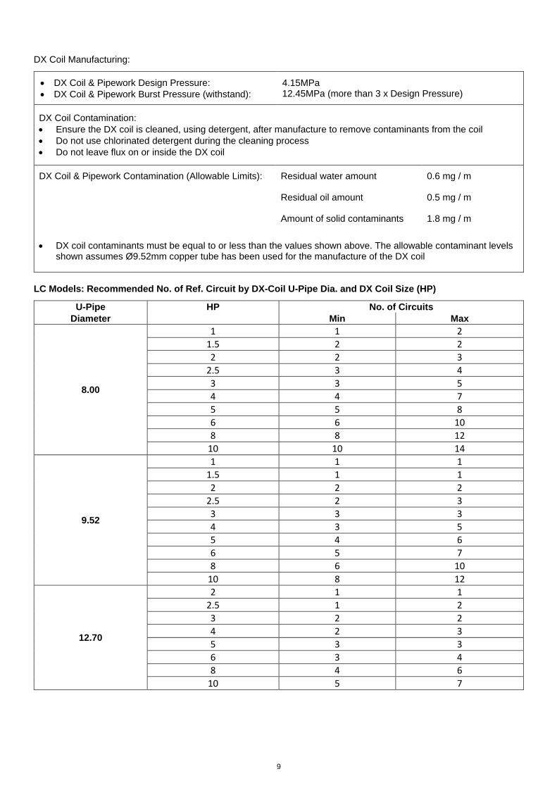
DX Coil Manufacturing:
DX Coil & Pipework Design Pressure:
DX Coil & Pipework Burst Pressure (withstand):
4.15MPa 12.45MPa (more than 3 x Design Pressure)
DX Coil Contamination:
Ensure the DX coil is cleaned, using detergent, after manufacture to remove contaminants from the coil
Do not use chlorinated detergent during the cleaning process
Do not leave flux on or inside the DX coil
DX Coil & Pipework Contamination (Allowable Limits): Residual water amount 0.6 mg / m
Residual oil amount 0.5 mg / m
Amount of solid contaminants 1.8 mg / m
DX coil contaminants must be equal to or less than the values shown above. The allowable contaminant levels shown assumes Ø9.52mm copper tube has been used for the manufacture of the DX coil
LC Models: Recommended No. of Ref. Circuit by DX-Coil U-Pipe Dia. and DX Coil Size (HP)
U-Pipe HP No. of Circuits
Diameter Min Max
8.00
1 1 2
1.5 2 2
2 2 3
2.5 3 4
3 3 5
4 4 7
5 5 8
6 6 10
8 8 12
10 10 14
9.52
1 1 1
1.5 1 1
2 2 2
2.5 2 3
3 3 3
4 3 5
5 4 6
6 5 7
8 6 10
10 8 12
12.70
2 1 1
2.5 1 2
3 2 2
4 2 3
5 3 3
6 3 4
8 4 6
10 5 7
10
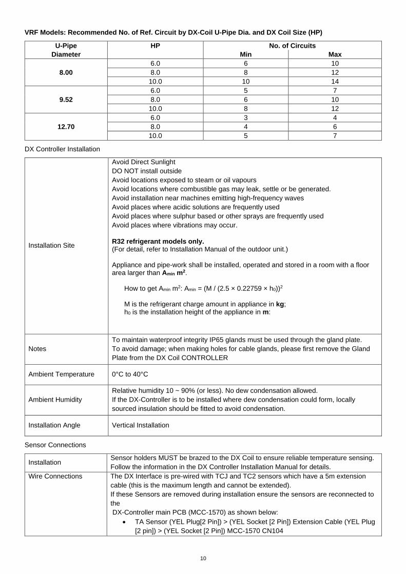
VRF Models: Recommended No. of Ref. Circuit by DX-Coil U-Pipe Dia. and DX Coil Size (HP)
U-Pipe HP No. of Circuits
Diameter Min Max
8.00
6.0 6 10
8.0 8 12
10.0 10 14
9.52
6.0 5 7
8.0 6 10
10.0 8 12
12.70
6.0 3 4
8.0 4 6
10.0 5 7
DX Controller Installation
Installation Site
Avoid Direct Sunlight
DO NOT install outside
Avoid locations exposed to steam or oil vapours
Avoid locations where combustible gas may leak, settle or be generated.
Avoid installation near machines emitting high-frequency waves
Avoid places where acidic solutions are frequently used
Avoid places where sulphur based or other sprays are frequently used
Avoid places where vibrations may occur.
R32 refrigerant models only. (For detail, refer to Installation Manual of the outdoor unit.) Appliance and pipe-work shall be installed, operated and stored in a room with a floor area larger than Amin m2.
How to get Amin m2: Amin = (M / (2.5 × 0.22759 × h0))2 M is the refrigerant charge amount in appliance in kg; h0 is the installation height of the appliance in m:
Notes
To maintain waterproof integrity IP65 glands must be used through the gland plate.
To avoid damage; when making holes for cable glands, please first remove the Gland
Plate from the DX Coil CONTROLLER
Ambient Temperature 0°C to 40°C
Ambient Humidity
Relative humidity 10 ~ 90% (or less). No dew condensation allowed.
If the DX-Controller is to be installed where dew condensation could form, locally
sourced insulation should be fitted to avoid condensation.
Installation Angle Vertical Installation
Sensor Connections
Installation Sensor holders MUST be brazed to the DX Coil to ensure reliable temperature sensing.
Follow the information in the DX Controller Installation Manual for details.
Wire Connections The DX Interface is pre-wired with TCJ and TC2 sensors which have a 5m extension
cable (this is the maximum length and cannot be extended).
If these Sensors are removed during installation ensure the sensors are reconnected to
the
DX-Controller main PCB (MCC-1570) as shown below:
TA Sensor (YEL Plug[2 Pin]) > (YEL Socket [2 Pin]) Extension Cable (YEL Plug
[2 pin]) > (YEL Socket [2 Pin]) MCC-1570 CN104
11
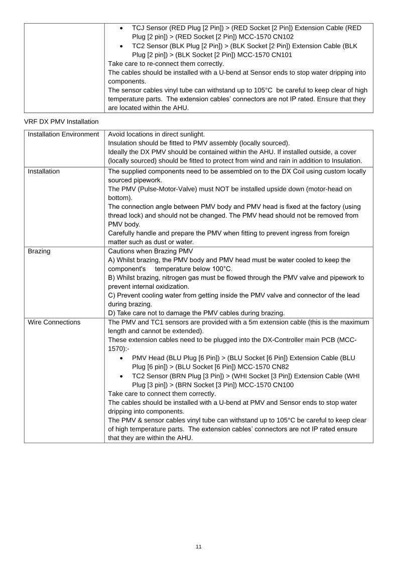
TCJ Sensor (RED Plug [2 Pin]) > (RED Socket [2 Pin]) Extension Cable (RED
Plug [2 pin]) > (RED Socket [2 Pin]) MCC-1570 CN102
TC2 Sensor (BLK Plug [2 Pin]) > (BLK Socket [2 Pin]) Extension Cable (BLK
Plug [2 pin]) > (BLK Socket [2 Pin]) MCC-1570 CN101
Take care to re-connect them correctly.
The cables should be installed with a U-bend at Sensor ends to stop water dripping into
components.
The sensor cables vinyl tube can withstand up to 105°C be careful to keep clear of high
temperature parts. The extension cables’ connectors are not IP rated. Ensure that they
are located within the AHU.
VRF DX PMV Installation
Installation Environment Avoid locations in direct sunlight.
Insulation should be fitted to PMV assembly (locally sourced).
Ideally the DX PMV should be contained within the AHU. If installed outside, a cover
(locally sourced) should be fitted to protect from wind and rain in addition to Insulation.
Installation The supplied components need to be assembled on to the DX Coil using custom locally
sourced pipework.
The PMV (Pulse-Motor-Valve) must NOT be installed upside down (motor-head on
bottom).
The connection angle between PMV body and PMV head is fixed at the factory (using
thread lock) and should not be changed. The PMV head should not be removed from
PMV body.
Carefully handle and prepare the PMV when fitting to prevent ingress from foreign
matter such as dust or water.
Brazing Cautions when Brazing PMV
A) Whilst brazing, the PMV body and PMV head must be water cooled to keep the
component's temperature below 100°C.
B) Whilst brazing, nitrogen gas must be flowed through the PMV valve and pipework to
prevent internal oxidization.
C) Prevent cooling water from getting inside the PMV valve and connector of the lead
during brazing.
D) Take care not to damage the PMV cables during brazing.
Wire Connections The PMV and TC1 sensors are provided with a 5m extension cable (this is the maximum
length and cannot be extended).
These extension cables need to be plugged into the DX-Controller main PCB (MCC-
1570):-
PMV Head (BLU Plug [6 Pin]) > (BLU Socket [6 Pin]) Extension Cable (BLU
Plug [6 pin]) > (BLU Socket [6 Pin]) MCC-1570 CN82
TC2 Sensor (BRN Plug [3 Pin]) > (WHI Socket [3 Pin]) Extension Cable (WHI
Plug [3 pin]) > (BRN Socket [3 Pin]) MCC-1570 CN100
Take care to connect them correctly.
The cables should be installed with a U-bend at PMV and Sensor ends to stop water
dripping into components.
The PMV & sensor cables vinyl tube can withstand up to 105°C be careful to keep clear
of high temperature parts. The extension cables’ connectors are not IP rated ensure
that they are within the AHU.
12
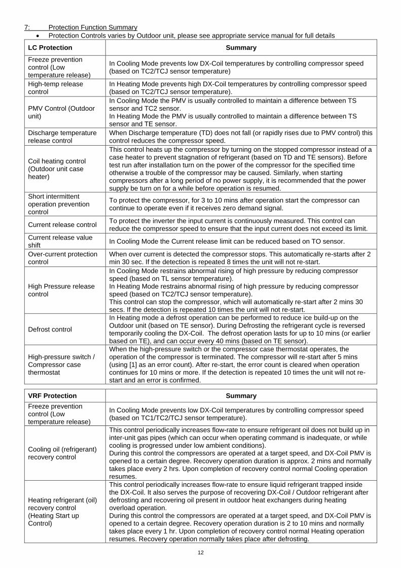
7: Protection Function Summary
Protection Controls varies by Outdoor unit, please see appropriate service manual for full details
LC Protection Summary
Freeze prevention control (Low temperature release)
In Cooling Mode prevents low DX-Coil temperatures by controlling compressor speed (based on TC2/TCJ sensor temperature)
High-temp release control
In Heating Mode prevents high DX-Coil temperatures by controlling compressor speed (based on TC2/TCJ sensor temperature).
PMV Control (Outdoor unit)
In Cooling Mode the PMV is usually controlled to maintain a difference between TS sensor and TC2 sensor. In Heating Mode the PMV is usually controlled to maintain a difference between TS sensor and TE sensor.
Discharge temperature release control
When Discharge temperature (TD) does not fall (or rapidly rises due to PMV control) this control reduces the compressor speed.
Coil heating control (Outdoor unit case heater)
This control heats up the compressor by turning on the stopped compressor instead of a case heater to prevent stagnation of refrigerant (based on TD and TE sensors). Before test run after installation turn on the power of the compressor for the specified time otherwise a trouble of the compressor may be caused. Similarly, when starting compressors after a long period of no power supply, it is recommended that the power supply be turn on for a while before operation is resumed.
Short intermittent operation prevention control
To protect the compressor, for 3 to 10 mins after operation start the compressor can continue to operate even if it receives zero demand signal.
Current release control To protect the inverter the input current is continuously measured. This control can reduce the compressor speed to ensure that the input current does not exceed its limit.
Current release value shift
In Cooling Mode the Current release limit can be reduced based on TO sensor.
Over-current protection control
When over current is detected the compressor stops. This automatically re-starts after 2 min 30 sec. If the detection is repeated 8 times the unit will not re-start.
High Pressure release control
In Cooling Mode restrains abnormal rising of high pressure by reducing compressor speed (based on TL sensor temperature). In Heating Mode restrains abnormal rising of high pressure by reducing compressor speed (based on TC2/TCJ sensor temperature). This control can stop the compressor, which will automatically re-start after 2 mins 30 secs. If the detection is repeated 10 times the unit will not re-start.
Defrost control
In Heating mode a defrost operation can be performed to reduce ice build-up on the Outdoor unit (based on TE sensor). During Defrosting the refrigerant cycle is reversed temporarily cooling the DX-Coil. The defrost operation lasts for up to 10 mins (or earlier based on TE), and can occur every 40 mins (based on TE sensor).
High-pressure switch / Compressor case thermostat
When the high-pressure switch or the compressor case thermostat operates, the operation of the compressor is terminated. The compressor will re-start after 5 mins (using [1] as an error count). After re-start, the error count is cleared when operation continues for 10 mins or more. If the detection is repeated 10 times the unit will not re-start and an error is confirmed.
VRF Protection Summary
Freeze prevention control (Low temperature release)
In Cooling Mode prevents low DX-Coil temperatures by controlling compressor speed (based on TC1/TC2/TCJ sensor temperature).
Cooling oil (refrigerant) recovery control
This control periodically increases flow-rate to ensure refrigerant oil does not build up in inter-unit gas pipes (which can occur when operating command is inadequate, or while cooling is progressed under low ambient conditions). During this control the compressors are operated at a target speed, and DX-Coil PMV is opened to a certain degree. Recovery operation duration is approx. 2 mins and normally takes place every 2 hrs. Upon completion of recovery control normal Cooling operation resumes.
Heating refrigerant (oil) recovery control (Heating Start up Control)
This control periodically increases flow-rate to ensure liquid refrigerant trapped inside the DX-Coil. It also serves the purpose of recovering DX-Coil / Outdoor refrigerant after defrosting and recovering oil present in outdoor heat exchangers during heating overload operation. During this control the compressors are operated at a target speed, and DX-Coil PMV is opened to a certain degree. Recovery operation duration is 2 to 10 mins and normally takes place every 1 hr. Upon completion of recovery control normal Heating operation resumes. Recovery operation normally takes place after defrosting.
13
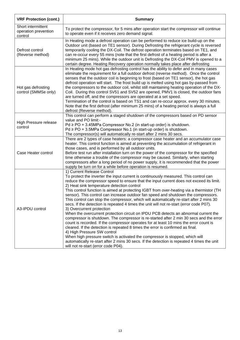
VRF Protection (cont.) Summary
Short intermittent operation prevention control
To protect the compressor, for 5 mins after operation start the compressor will continue to operate even if it receives zero demand signal.
Defrost control (Reverse method)
In Heating mode a defrost operation can be performed to reduce ice build-up on the Outdoor unit (based on TE1 sensor). During Defrosting the refrigerant cycle is reversed temporarily cooling the DX-Coil. The defrost operation terminates based on TE1, and can re-occur every 55 mins (note that the first defrost of a heating period is after a minimum 25 mins). While the outdoor unit is Defrosting the DX-Coil PMV is opened to a certain degree. Heating Recovery operation normally takes place after defrosting
Hot gas defrosting control (SMMSe only)
In Heating mode hot gas defrosting control has the ability to defer and in many cases eliminate the requirement for a full outdoor defrost (reverse method). Once the control senses that the outdoor coil is beginning to frost (based on TE1 sensor), the hot gas defrost operation will start. The frost build up is melted using hot gas by-passed from the compressors to the outdoor coil, whilst still maintaining heating operation of the DX-Coil. During this control SV51 and SV52 are opened, PMV1 is closed, the outdoor fans are turned off, and the compressors are operated at a set speed. Termination of the control is based on TS1 and can re-occur approx. every 30 minutes. Note that the first defrost (after minimum 25 mins) of a heating period is always a full defrost (Reverse method).
High Pressure release control
This control can perform a staged shutdown of the compressors based on PD sensor value and PO limit:- Pd ≥ PO = 3.45MPa Compressor No.2 (in start-up order) is shutdown. Pd ≥ PO = 3.5MPa Compressor No.1 (in start-up order) is shutdown. The compressor(s) will automatically re-start after 2 mins 30 secs.
Case Heater control
There are 2 types of case heaters: a compressor case heater and an accumulator case heater. This control function is aimed at preventing the accumulation of refrigerant in those cases, and is performed by all outdoor units. Before test run after installation turn on the power of the compressor for the specified time otherwise a trouble of the compressor may be caused. Similarly, when starting compressors after a long period of no power supply, it is recommended that the power supply be turn on for a while before operation is resumed.
A3-IPDU control
1) Current Release Control To protect the inverter the input current is continuously measured. This control can reduce the compressor speed to ensure that the input current does not exceed its limit. 2) Heat sink temperature detection control This control function is aimed at protecting IGBT from over-heating via a thermistor (TH sensor). This control can increase outdoor fan speed and shutdown the compressors. This control can stop the compressor, which will automatically re-start after 2 mins 30 secs. If the detection is repeated 4 times the unit will not re-start (error code P07). 3) Overcurrent protection When the overcurrent protection circuit on IPDU PCB detects an abnormal current the compressor is shutdown. The compressor is re-started after 2 min 30 secs and the error count is recorded. If the compressor operates for at least 10 mins the error count is cleared. If the detection is repeated 8 times the error is confirmed as final. 4) High Pressure SW control When high pressure switch is activated the compressor is stopped, which will automatically re-start after 2 mins 30 secs. If the detection is repeated 4 times the unit will not re-start (error code P04).
14
8 Cable specifications
Description Max. Cable Length (m) Cable Specification
LC Outdoor / Indoor Interconnect See Outdoor unit Installation
Manual H07 RH-F / 60245 IEC 66 (1.5mm2 or more)
VRF DX Controller Power Supply See Outdoor unit Installation
Manual 60245 IEC 57
Analogue input (AI1) 200 Screened cable: 0.5 ~ 1.0mm 2
Digital input (DI1 / DI2) 100 Non screened cable: 0.5 ~ 1.0mm 2
Digital output (DO1 / DO2) 500 Non screened cable: 0.5 ~ 1.0mm 2
Remote Controller (AB) 500 Non screened cable: 0.75 ~ 2.5mm 2
VRF Control (U1/U2) 1000 Screened cable: ≥1.5mm 2
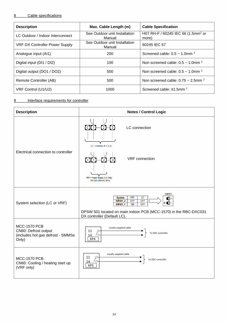
9 Interface requirements for controller
Description Notes / Control Logic
Electrical connection to controller
LC connection
VRF connection
System selection (LC or VRF)
DPSW 501 located on main indoor PCB (MCC-1570) in the RBC-DXC031 DX controller (Default LC).
MCC-1570 PCB CN60: Defrost output (includes hot gas defrost - SMMSe Only)
MCC-1570 PCB CN60: Cooling / heating start up (VRF only)
11
14KP4
To DDC controller
Locally supplied cable
11
14KP5
To DDC controller
Locally supplied cable
15
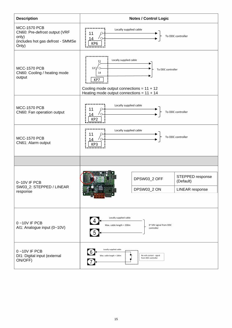
Description Notes / Control Logic
MCC-1570 PCB CN60: Pre-defrost output (VRF only) (includes hot gas defrost - SMMSe Only)
MCC-1570 PCB CN60: Cooling / heating mode output
Cooling mode output connections = 11 + 12 Heating mode output connections = 11 + 14
MCC-1570 PCB CN60: Fan operation output
MCC-1570 PCB CN61: Alarm output
0~10V IF PCB SW03_2: STEPPED / LINEAR response
DPSW03_2 OFF STEPPED response (Default)
DPSW03_2 ON LINEAR response
0 ~10V IF PCB AI1: Analogue input (0~10V)
0 ~10V IF PCB DI1: Digital input (external ON/OFF)
4
5
0~10V signal from DDC controller
Locally supplied cable
Max. cable length = 200m
6
7
Locally supplied cable
No volt contact - signal from DDC controller
Max. cable length = 100m
11
14KP6
To DDC controller
Locally supplied cable
14
12
KP7
To DDC controller
Locally supplied cable11
11
14KP2
To DDC controller
Locally supplied cable
11
14KP3
To DDC controller
Locally supplied cable
16
Description Notes / Control Logic
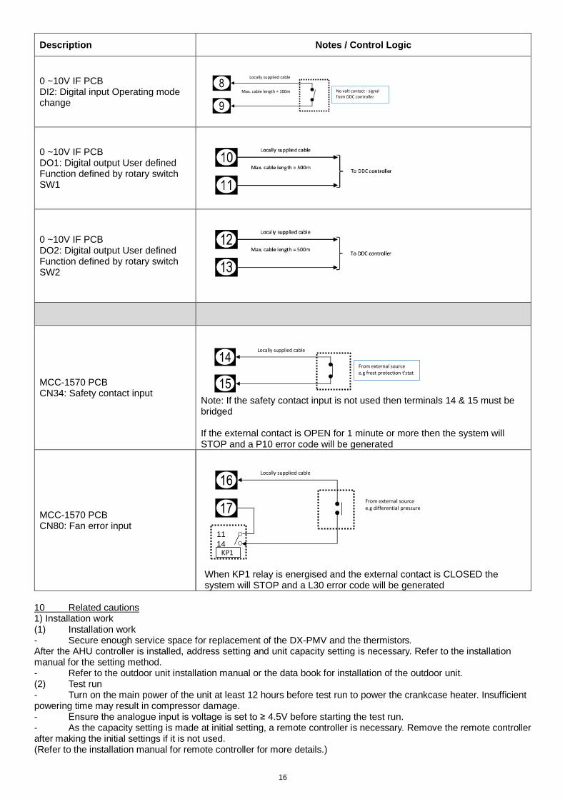
0 ~10V IF PCB DI2: Digital input Operating mode change
0 ~10V IF PCB DO1: Digital output User defined Function defined by rotary switch SW1
0 ~10V IF PCB DO2: Digital output User defined Function defined by rotary switch SW2
MCC-1570 PCB CN34: Safety contact input
Note: If the safety contact input is not used then terminals 14 & 15 must be bridged If the external contact is OPEN for 1 minute or more then the system will STOP and a P10 error code will be generated
MCC-1570 PCB CN80: Fan error input
When KP1 relay is energised and the external contact is CLOSED the system will STOP and a L30 error code will be generated
10 Related cautions 1) Installation work (1) Installation work - Secure enough service space for replacement of the DX-PMV and the thermistors. After the AHU controller is installed, address setting and unit capacity setting is necessary. Refer to the installation manual for the setting method. - Refer to the outdoor unit installation manual or the data book for installation of the outdoor unit. (2) Test run - Turn on the main power of the unit at least 12 hours before test run to power the crankcase heater. Insufficient powering time may result in compressor damage. - Ensure the analogue input is voltage is set to ≥ 4.5V before starting the test run. - As the capacity setting is made at initial setting, a remote controller is necessary. Remove the remote controller after making the initial settings if it is not used. (Refer to the installation manual for remote controller for more details.)
8
9
Locally supplied cable
No volt contact - signal from DDC controller
Max. cable length = 100m
14
15
Locally supplied cable
From external sourcee.g frost protection t'stat
11
14
16
17
Locally supplied cable
KP1
From external sourcee.g differential pressure
17
(3) Operation control
If the error display appears on the remote controller, do not reset an error by yourself. Contact the service firm or the dealer.
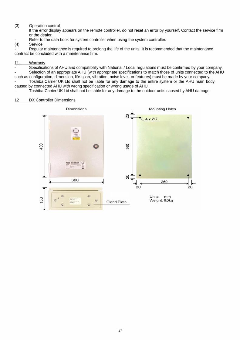
- Refer to the data book for system controller when using the system controller. (4) Service - Regular maintenance is required to prolong the life of the units. It is recommended that the maintenance contract be concluded with a maintenance firm. 11. Warranty - Specifications of AHU and compatibility with National / Local regulations must be confirmed by your company. - Selection of an appropriate AHU (with appropriate specifications to match those of units connected to the AHU such as configuration, dimension, life-span, vibration, noise level, or features) must be made by your company. - Toshiba Carrier UK Ltd shall not be liable for any damage to the entire system or the AHU main body caused by connected AHU with wrong specification or wrong usage of AHU. - Toshiba Carrier UK Ltd shall not be liable for any damage to the outdoor units caused by AHU damage. 12 DX Controller Dimensions
18
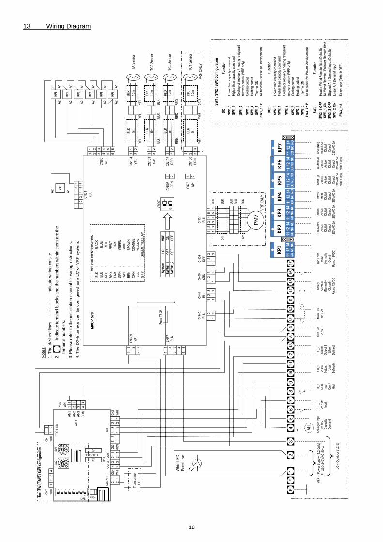
13 Wiring Diagram
TC
2 S
enso
r5m
YE
LY
EL
YE
L
SW
501
BLK
BLK
BLK
Fus
e T
6.3A
Sys
tem
LC
VR
F
BLK
BLK
TA
Sen
sor
5m1.
2m
1.2m
BLK
22
BLK
CN
101
11
SW3
1
LD3
LD2
LD1
2
D/O
OU
T 2
O
UT
1
+-
AC
24V
IN
21
CN
4
21
WH
I4
32
1O
RN
21
CN
3
23
4W
HI
12
See
: S
W1
/ SW
2 / S
W3
Co
nfi
gu
rati
on
Note
sC
N7
CN
11
21
. T
he d
ash
ed
lin
es
in
dic
ate
wirin
g o
n s
ite
.W
HI
1
SW
2S
W1
TC
C-L
INK
2.
ind
ica
te t
erm
ina
l b
locks a
nd
th
e n
um
be
rs w
ith
in t
he
m a
re t
he
KP
3C
N5
term
ina
l n
um
be
rs.
WH
I
Ana
logu
e In
put
(0-1
0V)
Cap
acity
Dem
and
A/I
1
6
BLU
:B
LUE
21
D/I
43K
2
TX-TOS1413
K1
1C
N2
A1
AN
22
24
. T
he D
X-I
nte
rfa
ce
ca
n b
e c
on
figu
red
as a
LC
or
VR
F s
yste
m.
KP
4
A1
AN
11
13
. P
lea
se r
efe
r to
th
e in
sta
llatio
n m
an
ua
l fo
r w
irin
g instr
uctio
ns.
A2
A1
A2
56
KP
5
AN
33
A2
CO
M4
4C
N61
KP
6A
2A
1
22
23
45
A1
YE
L1
1K
P7
MC
C-1
570
A2
CO
LOU
R ID
EN
TIF
ICA
TIO
N
BLK
:B
LAC
K
RE
D:
RE
D
33
A2
44
WH
I
GR
YK
P1
WH
I:
WH
ITE
A2
CN
60
WH
I5
5:
GR
EY
KP
2
66
PN
K:
PIN
K6
54
3
43
11
BR
N:
BR
OW
NC
N30
9O
RA
NG
E
GR
N:
GR
EE
N
A1
:Y
ELL
OW
G /
Y:
GR
EE
N /
YE
LLO
W
BLK
Tra
nsfo
rmer
2O
RN
:Y
EL
33
YE
L
11
22
CN
104
YE
L
A1
TC
J S
enso
rR
ED
22
11
BLK
RE
DC
N67
SW
501_
1O
FF
ON
CN
103
1
33
Whi
te L
ED
Pan
el L
ive
RE
DR
ED
RE
D4
5
25m
1.2m
BLK
SW
501_
2O
FF
OF
FG
RN
2
CN
102
11
33
51
1C
N73
1B
LK 5mW
HI
2
VR
F O
NLY
BLU
BLU
GR
NR
ED
BLU
CN
40C
N41
CN
80C
N34
CN
82W
HI
WH
IB
RN
BLU
1.2m
TC
1 S
enso
rC
N10
02
BR
N
12
13
23
12
12
12
31 1
31
3
23
4
BLU
SW
1 / S
W2
/ SW
3 C
on
fig
ura
tio
n
5mB
LKD
O1
Fu
nct
ion
12
34
56
56
31
SW
1_0
Low
er th
an c
apac
ity c
omm
and
BLU
SW
1_1
SW
1_4
Hea
ting
outp
ut
Hig
her
than
cap
acity
com
man
dB
LU
SW
1_2
Coo
ling
oil r
ecov
ery
/ hea
ting
refr
iger
ant
reco
very
con
trol
(V
RF
onl
y)
SW
1_5
The
rmo
ON
VR
F O
NLY
SW
1_6
~ F
No
func
tion
(For
Fut
ure
Dev
elop
men
t)
DO
2F
un
ctio
n
0.6m
BLK
SW
1_3
Coo
ling
outp
ut
SW
2_0
Low
er th
an c
apac
ity c
omm
and
SW
2_1
Hig
her
than
cap
acity
com
man
d
SW
2_2
DI_
2
Mod
e
Inpu
t
Coo
l /
Hea
t
D0_
1
Dig
ital
Out
put 1
(U
ser
Def
ined
)
D0_
2
Dig
ital
Out
put 2
(U
ser
Def
ined
)
Sub
Bus
A /
B
Mai
n B
us
U1
/ U2
Saf
ety
Con
tact
(Nor
mal
ly
Clo
sed)
Rat
ing
12V
DC
Coo
ling
oil r
ecov
ery
/ hea
ting
refr
iger
ant
reco
very
con
trol
(V
RF
onl
y)
SW
2_3
Coo
ling
outp
ut
SW
2_4
Hea
ting
outp
ut
SW
2_5
The
rmo
ON
Ste
pped
AI1
Dem
and
Inpu
t (D
efau
lt)
LC =
Out
door
(1,
2,3)
SW
3_2_
ON
Line
ar A
I1 D
eman
d In
put
SW
3_2~
8D
o no
t use
(D
efau
lt O
FF
)
Coo
l (N
O)
Hea
t (N
C)
Dig
ital
Out
put
250V
AC
6A
SW
3F
un
ctio
nV
RF
= P
ower
Sup
ply
(1,2
Onl
y)
1
Ph
220~
240V
AC
50H
z
SW
3_1_
OF
FH
eade
r W
ired
Rem
ote
fitte
d (D
efau
lt)
SW
3_1_
ON
No
Wire
d R
emot
e / F
ollo
wer
Rem
ote
fitte
d
SW
3_2_
OF
F
Fan
Err
or
Inpu
t
(Nor
mal
ly
Ope
n)
Rat
ing
12V
DC
Fan
Mot
or
Act
ive
Dig
ital
Out
put
250V
AC
6A
Ala
rm
Act
ive
Dig
ital
Out
put
250V
AC
6A
Def
rost
Mod
e
Dig
ital
Out
put
250V
AC
6A
Sta
rt U
p
Con
trol
Act
ive
Dig
ital
Out
put
250V
AC
6A
(VR
F O
nly)
Pre
-def
rost
Con
trol
Act
ive
Dig
ital
Out
put
250V
AC
6A
(VR
F O
nly)
AI1
SW
2_6
~ F
No
func
tion
(For
Fut
ure
Dev
elop
men
t)
DI_
1
On
/ Off
Inpu
t
E5
43
21
1617
76
PM
V
98
1011
12E
BA
U2
U1
1315
2
ON
18 7 6 5 4 3
ON
12
E11
C
O
12
NC
14 NO
KP1
11
CO
12
NC
14 NO
KP2
11
CO
12
NC
14 NO
KP3
11
CO
12
NC
14 NO
KP4
11
CO
12
NC
14 NO
KP5
11
CO
12
NC
14 NO
KP6
11
CO
12
NC
14 NO
KP7
14
19
DG002.04 01/2020
Toshiba Carrier (UK) Ltd Porsham Close Belliver Industrial Estate Plymouth Devon United Kingdom PL6 7DB
+44 (0) 1752 753200
+44 (0) 1752 753222