˘ ˆ ˙ ˘ ˘ - White Rose Research Onlineeprints.whiterose.ac.uk/83451/8/morley nonedited...
23
This is a repository copy of Study of the magnetic-Alq3 interface in organic spin-valves . White Rose Research Online URL for this paper: http://eprints.whiterose.ac.uk/83451/ Version: Accepted Version Article: Morley, N.A., Drew, A.J., Zhang, H. et al. (3 more authors) (2014) Study of the magnetic-Alq3 interface in organic spin-valves. Applied Surface Science, 313. 850 - 857. ISSN 0169-4332 https://doi.org/10.1016/j.apsusc.2014.06.088 [email protected] https://eprints.whiterose.ac.uk/ Reuse Unless indicated otherwise, fulltext items are protected by copyright with all rights reserved. The copyright exception in section 29 of the Copyright, Designs and Patents Act 1988 allows the making of a single copy solely for the purpose of non-commercial research or private study within the limits of fair dealing. The publisher or other rights-holder may allow further reproduction and re-use of this version - refer to the White Rose Research Online record for this item. Where records identify the publisher as the copyright holder, users can verify any specific terms of use on the publisher’s website. Takedown If you consider content in White Rose Research Online to be in breach of UK law, please notify us by emailing [email protected] including the URL of the record and the reason for the withdrawal request.
Transcript of ˘ ˆ ˙ ˘ ˘ - White Rose Research Onlineeprints.whiterose.ac.uk/83451/8/morley nonedited...

This is a repository copy of Study of the magnetic-Alq3 interface in organic spin-valves.
White Rose Research Online URL for this paper:http://eprints.whiterose.ac.uk/83451/
Version: Accepted Version
Article:
Morley, N.A., Drew, A.J., Zhang, H. et al. (3 more authors) (2014) Study of the magnetic-Alq3 interface in organic spin-valves. Applied Surface Science, 313. 850 - 857. ISSN 0169-4332
https://doi.org/10.1016/j.apsusc.2014.06.088
[email protected]://eprints.whiterose.ac.uk/
Reuse
Unless indicated otherwise, fulltext items are protected by copyright with all rights reserved. The copyright exception in section 29 of the Copyright, Designs and Patents Act 1988 allows the making of a single copy solely for the purpose of non-commercial research or private study within the limits of fair dealing. The publisher or other rights-holder may allow further reproduction and re-use of this version - refer to the White Rose Research Online record for this item. Where records identify the publisher as the copyright holder, users can verify any specific terms of use on the publisher’s website.
Takedown
If you consider content in White Rose Research Online to be in breach of UK law, please notify us by emailing [email protected] including the URL of the record and the reason for the withdrawal request.

Accepted Manuscript
Title: Study of the magnetic-Alq3 interface in organic
spin-valves
Author: N.A. Morley A.J. Drew H. Zhang K. Scott S.
Hudziak D.J. Morgan
PII: S0169-4332(14)01390-7
DOI: http://dx.doi.org/doi:10.1016/j.apsusc.2014.06.088
Reference: APSUSC 28137
To appear in: APSUSC
Received date: 4-12-2013
Revised date: 21-5-2014
Accepted date: 15-6-2014
Please cite this article as: N.A. Morley, A.J. Drew, H. Zhang, K. Scott, S. Hudziak, D.J.
Morgan, Study of the magnetic-Alq3 interface in organic spin-valves, Applied Surface
Science (2014), http://dx.doi.org/10.1016/j.apsusc.2014.06.088
This is a PDF file of an unedited manuscript that has been accepted for publication.
As a service to our customers we are providing this early version of the manuscript.
The manuscript will undergo copyediting, typesetting, and review of the resulting proof
before it is published in its final form. Please note that during the production process
errors may be discovered which could affect the content, and all legal disclaimers that
apply to the journal pertain.
Page 1 of 21
Accep
ted
Man
uscr
ipt
Study of the magnetic-Alq3 interface in organic spin-valves
N. A Morley1*
, A. J. Drew2, H. Zhang
2, K. Scott
2, S. Hudziak
3 and D. J. Morgan
4
1Department of Materials Science and Engineering, University of Sheffield, Sheffield, S1 3JD,
UK 2School of Physics and Astronomy, Queen Mary University of London, Mile End Road, London,
E1 4NS, UK 3Electronic & Electrical Engineering, University College London, London, WC1E 7JE, UK
4Cardiff Catalysis Institute, School of Chemistry, Cardiff University, Cardiff, CF10 3AT, UK
*Corresponding author e-mail: [email protected]
Abstract
The interface between the organic semiconductor tris(8-hydrixyquinolate) aluminium (Alq3) and
two different magnetic electrodes has been investigated using X-ray photoelectron spectroscopy
(XPS), Kelvin Probe, atomic force microscopy (AFM) and Magneto-optic Kerr effect (MOKE)
magnetometry. The transition metal magnetic electrode/Alq3 films were first measured using a
XPS, and then washed and remeasured. It was found that Alq3 still existed on the magnetic
electrode after washing. This suggests that the Alq3 chemisorbs onto the transition metal
electrode surfaces. Using MOKE magnetometry, the surface magnetisation of the transition
metal electrodes was studied. It was found that the surface magnetisation of the NiFe electrode
changed with the Alq3 layer on top, which was taken to be due to the Alq3 chemisorption onto
the NiFe electrode, so changing the electronic states at the interface.
Keywords: organic spintronics; interfaces; XPS;
Introduction
Organic spintronics studies the behaviour of spin carriers in organic semiconductors, including
the transportation using the organic semiconductor as the spacer layer between the two magnetic
electrodes in a spin-valve. The advantages of organic semiconductors for spintronic applications
include their cost, ease of fabrication and long spin diffusion time, due to the relatively weak
spin-orbit coupling and hyperfine interaction [1]. The first demonstration of an organic spin-
valve by Xiong et al [2] was a La0.67Sr0.33MnO2 (LSMO)/tris(8-hydrixyquinolate) aluminium
(Alq3)/Co device. They measured a magnetoresistance (MR) of ~ 40% at 11K, but no MR was
measured at temperatures above 150K. Since then one of the main focuses of research into
organic spin-valves has been on achieving room temperature magnetoresistance, with a range of
magnetic electrodes (e.g. LSMO, Co, FeCo, NiFe [3-6]) and organic semiconductors (e.g. Alq3,
P3HT, rubrene [3-10]). To date, the highest MRs achieved at room temperature for the organic
semiconductor layer thicker than 50nm are MR= -0.15% for LSMO/100nm Alq3/Co [11], MR=
3% for LSMO/100nm P3HT/Co[7] and MR= -0.45% for CoPt/TIPS-pentacene/Co [12].
Page 2 of 21
Accep
ted
Man
uscr
ipt
Research has also focussed on how the interface between the magnetic electrode and the organic
semiconductor influences the spin injection and detection of the charge carriers into/from the
organic semiconductor. It has been suggested [13] that the organic semiconductor strongly bonds
to the surface of the bottom electrode, such that it changes the electronic structure of the
electrode, and hence changes the interfacial properties. The bonding can occur due to two
different processes [13], the first is physisorption, where the molecule’s electron cloud “pushes”
the metal’s surface wavefunction, causing the work function to be lowered, and there is no
overlap of the wavefunctions. The second is chemisorption, where charge transfer occurs
between the metal and the molecule, which may form a strong interface dipole, thus a strong
electronic coupling. Barraud et al [14] put forward the spin-hydridization-induced polarised
states (SHIPS) model which hypothesises that the first molecular layer on the magnetic electrode
changes the spin polarisation states at the surface of the magnetic electrode, thus changing the
MR of the device. Steil et al [15] demonstrated these hybrid interface states using two-photon
photoemission on a Co/Alq3 interface. They found that the electrons are trapped in these hybrid
states, allowing the interfaces to act as spin filters. These hybrid states form due to the Alq3
chemisorbing into the Co, so that there is an interaction between the molecular orbitals of the
Alq3 and the metallic bands of Co. Majumdar et al [16] showed that using self assembling
molecules (SAMS) between the bottom electrode and RR-P3HT could annihilate the MR
measured, by destroying these interface sates. Morley et al [17] have shown that the RR-P3HT
bonded strongest to LSMO, while exhibiting weaker bonding to the transition metal electrodes. It
was also found that the bonding depended on the electrode surface roughness and the solvent
used to spin-coat the polymer.
The interface between the top electrode and the organic semiconductor has also been studied, by
investigating different interface layers between them. Schulz et al [18], Dhandapani et al [5] and
Szulczewshi et al [19] all investigated using LiF as an interface layer between Alq3 and the top
electrode. Dhandapani showed that it improved the MR of FeCo/Alq3/NiFe spin-valves, while
Schulz showed that the presence of LiF reversed the net extracted spin polarisation at the NiFe
cathode, which resulted in the change in sign of the MR. This was argued to be due to the
electric dipole moments of the LiF modifying the vacuum level of the Alq3, thus changing the
NiFe band that was relevant for hole extraction Szulczewshi showed that the LiF layer lowered
the work function of the top magnetic electrode used by 1.4eV, confirming the explanation of
MR sign reversal by Schulz et al. Another study used Al2O3 as the interface layer between the
ferromagnetic electrode and organic semiconductor, which acted as a tunnel barrier to the spin
carriers being extracted from the organic semiconductor, and it was argued to also reduce the
penetration of the top electrode into the organic semiconductor [11]. Using Al2O3, Dediu et al
[10] achieved a room temperature MR ca. -0.15% for a LSMO/Alq3/Al2O3/Co spin-valve.
Page 3 of 21
Accep
ted
Man
uscr
ipt
Thus understanding the bonding at the interfaces between the magnetic electrodes and the
organic semiconductor is important, so that the magnetic-organic interface models presented,
(such as SHIPS [14]) can be verified, as well as improving the development of spin device
designs. In this letter we report a study of the interface between Alq3 and two different magnetic
transition metal alloys, to determine the type of bonding present at the interface, and whether any
change in the electronic states caused by the interfacial bonding can be observed.
Experimental Procedure
We studied two different magnetic electrodes with the organic semiconductor Alq3 on top, plus
for comparison two plain magnetic electrodes were also studied. The samples were fabricated on
glass substrates, which were cleaned using acetone and IPA. The Fe50Co50 (FeCo) and Ni81Fe19
(NiFe) films were grown onto the glass substrates using RF sputtering from 150mm diameter
alloy targets with known compositions (50:50 FeCo and 81:19 NiFe). The 40nm FeCo films
were grown at a pressure of 4.5mTorr and a power density of 2kWm-2
and the 40nm NiFe films
were grown at a pressure of 4.5mTorr and a power density of 1kWm-2
. On top of each of the
magnetic electrodes was thermally evaporated a 10nm Alq3 film, in a vacuum system with a base
pressure of ~10-7
mbar. The deposition rate was between 0.1nm/s and 0.2nm/s. The
Alq3 purchased from Sigma Aldrich (99.995% purity) was further purified by train sublimation
in a vacuum of ~10-6
mbar before being used. The first series of samples characterised were
40nm FeCo, 40nm NiFe, 40nm FeCo/10nm Alq3 and 40nm NiFe/10nm Alq3. After the initial
MOKE measurements, which demonstrated a change in the magnetisation hysteresis loop for the
NiFe/Alq3 film compared to the NiFe film, a second series of samples were fabricated to further
investigate this result. The samples fabricated had different thicknesses of NiFe layers (10nm,
20nm and 40nm) with a 10nm Alq3 layer grown on top.
To characterise the interface of the magnetic-organic samples, four different techniques were
used: X-ray photoelectron spectroscopy (XPS), Kelvin probe, atomic force microscopy (AFM)
and magneto-optic Kerr effect (MOKE) magnetometry. The XPS spectra were analysed using a
Kratos Axis Ultra DLD photoelectron spectrometer, incorporating a 165 mm radius analyser
using monochromatic Al source operating at 144 W (12 mA x 12 kV), at a pass energy of 40 eV
for high resolution scans (energy resolution measured to be 0.76 eV on silver for pass energy
employed) and 160 eV for survey scans and operating in the hybrid spectroscopy mode, covering
an analysis area of approximately 700x400 µm. Four samples (FeCo film, NiFe film, FeCo/Alq3
film and NiFe/Alq3 film) were investigated using a XPS to determine the affect of Alq3 on the
magnetic electrodes. The first set of XPS measurements obtained spectra for the as-prepared
samples. The samples were then taken from the XPS and washed using acetone and then
chloroform in order to remove the Alq3 from the electrode surfaces. This method was used by
Majumdar et al [16] in their study of the LMSO/RR-P3HT interface and Morley et al [17] in a
previous study of magnetic electrode/RR-P3HT interface. If the Alq3 is strongly bonded
(chemisorbed) to the magnetic electrode surface, then a layer of Alq3 may still be on the surface
after washing. If the Alq3 is weakly or non-bonded (physisorbed) to the magnetic electrode, then
Page 4 of 21
Accep
ted
Man
uscr
ipt
it is more likely that significantly more, if not all of the Alq3 layer will be removed by washing.
After washing, the samples were then reloaded into the XPS, and the spectra remeasured. Due to
the solvent washing, all the samples were calibrated to the C(1s) signal at 285eV consistent with
the XPS of any organic residues that may remain. All the calibrated XPS spectra were curve-
fitted using CasaXPS using a Gaussian-Lorentzian mixed lineshape [20], which allowed all the
peaks to be identified. Further studies of the electrode surface were made using atomic force
microscopy (AFM), using a Digital Instruments Dimension 3000 force microscope, in tapping
mode. These measurements gave the surface roughness, as well as 3D images of the surfaces.
The work function (WF) of each surface was measured using a Kevin Probe (ASKP200200). The
5mm diameter stainless steel tip was lowered close to the surface until a WF gradient of >300
was achieved. Each sample was then grounded from the top surface using a copper clamp, and
300 points were measured to determine the mean WF. The WF of the tip was first calibrated by
measuring the WF of two known samples, gold (Au) and aluminium (Al). The normalised
magnetisation loops of the magnetic electrodes were measured on a MOKE magnetometer, from
these loops the anisotropy field (Hk), coercive field (Hc) and remenant magnetisation (MR) were
determined [21].
Results and Discussion
For each sample, a “wide” XPS spectrum was taken, this was to determine the main elements
present at the surface of each scan. It also allowed any differences between the as-grown and
washed samples to be identified. From Figure 1, it is observed that the transition metal electrode
surfaces had a thin oxide layer present. This occurred as the growth of the magnetic electrode
and the Alq3 occurred in different deposition systems, such that the magnetic electrode surface
was exposed to atmosphere. The percentage of oxygen on the surface of the FeCo was 80%,
while for NiFe the percentage was 50%. Thus the FeCo electrode has a thicker oxide layer
compared to the NiFe and was further confirmed by x-ray reflectivity (XRR) data [22]. It is also
observed that the FeCo/Alq3 (as-grown and washed) and the NiFe/Alq3 (as-grown and washed)
spectra have a small peak for N(1s) due to the Alq3, while the FeCo and NiFe electrode spectra
do not. The ratio of the elements present at the surface can be determined from the wide
spectrum. It was found that for the FeCo electrode the composition was Fe=44% and Co=56% so
slightly richer in Co than expected and for the NiFe electrode the composition was Ni=61% and
Fe=39%, so richer in Fe than the growth composition, but consistent with other measurements of
the surface [17, 22].
As Alq3 contains nitrogen and aluminium, the N(1s) and Al(2p) peaks were investigated using
XPS. From Figure 2a, it is observed that the N(1s) spectra for the FeCo electrodes (as-grown and
washed) has two peaks at 397.4eV and 400.1eV, with the 397.4eV peak being larger than the
400.1eV peak. These peaks correspond to metal nitrides and C-N bonds respectively. For the
FeCo/Alq3 (as-grown) has one large peak at 399.7eV, which is due to Alq3 film, as it contains C-
Page 5 of 21
Accep
ted
Man
uscr
ipt
N bonds [23]. For the FeCo/Alq3 (washed), two peaks again are observed in the N(1s) spectrum
at 397eV and 399.9eV, with the 399.9eV peak being larger than the 397eV peak. As the 399.9eV
is due to the C-N bond in Alq3 and the peak is larger than the 397eV, this means there is still
Alq3 present on the surface of the FeCo. A similar behaviour is observed in the NiFe/Alq3
spectra, where for the NiFe (washed and as-grown) electrodes, the two peaks occur at 397.5eV
and 399.9eV, with the 397.5eV peak being the largest peak. For the NiFe/Alq3 (as-grown) N(1s)
spectrum one peak was measured at 399.7eV due to the Alq3 film [23]. Then after washing the
NiFe/Alq3 (washed) N(1s) spectrum had two peak at 397.6eV and 399.9eV, with the later having
a larger concentrating, indicating Alq3 remains present on the NiFe surface after washing. For the
Al(2p) spectra (Fig. 3), it is observed that the FeCo/Alq3 (as-grown) and the NiFe/Alq3 (as-
grown) surfaces have a peak at 74.1eV, which corresponds to the Alq3 film [24]. For the
FeCo/Alq3 (washed) surface, the peak at 74.1eV is observed, although as expected the peak
magnitude is reduced, due to the removal of most of the Alq3 after washing. For the NiFe/Alq3
(washed) surface, no Al peak is observed as a consequence of the overlapping Ni(3p) region,
which dominates the Al(2p) signal (Fig. 3). For the NiFe/Alq3 (as-grown), a much smaller Ni(3p)
peak was measured, due to the Alq3 film thickness of ~10nm dominating the XPS spectra,
meaning that the Al(2p) peak is observed the measured spectra. For consistency, the O(1s) peaks
(Figs. 4) were studied for all four samples (as-grown and washed). For the transition metals
electrodes (washed and as-grown), the two peaks occur at binding energies (B.E) of 529.3eV and
531.1eV, which correspond to metal oxides and hydroxides present at the surface and are typical
of transition metal oxides. The NiFe electrode also has an additional shallow peak at 534eV. For
the FeCo/Alq3 (as-grown) and NiFe/Alq3 (as-grown) films, it is observed that the largest peak is
at 531.4eV, which is due to the Alq3 film [23] with a smaller one at 529eV and a very small peak
above 534.5 eV. The latter peak is likely to be either due to Na Auger electrons or an O(1s)
resonance. For the FeCo/Alq3 (washed) surface, the two oxide peaks are back to the same ratio
and same B.E.s as the FeCo (washed) surface O(1s) peaks. This suggests that after washing, if
any Alq3 is still present on the surface of the FeCo, the O(1s) 531.4eV peak is too small to be
detected using XPS compared to the metal oxide peaks. While for the NiFe/Alq3 (washed)
surface the two main peaks are of similar height, which is different from both the NiFe/Alq3 (as-
grown) and NiFe(as-grown and washed) surfaces. This suggests that there is still Alq3 present on
the NiFe surface, as the spectra is not the same as the NiFe electrodes, but the majority of the
Alq3 has been removed. The O(1s) and N(1s) core levels values are in good agreement, with
other studies of Alq3 on surfaces such as Al [24, 25] and CaF2 [26].
Comparing all the XPS spectra, it is observed that there is still Alq3 present after washing
meaning that the Alq3 has more strongly bonded to the magnetic surface. This suggests that the
bonding is achieved via chemisorption rather than the much weaker physisorption [13]. It is also
observed that the Alq3 bonds stronger to the FeCo electrode compared to the NiFe electrodes.
This is concluded as the peaks associated with Alq3 in the N(1s) and Al(2p) are larger in
magnitude for the FeCo/Alq3 (washed) surface compared to the NiFe/Alq3 (washed) surface.

Page 6 of 21
Accep
ted
Man
uscr
ipt
This could be due to the FeCo surface being ~80% oxide compared to the ~50% oxide for NiFe
and the Alq3 chemisorbing stronger to an oxide rather than the transition metal.
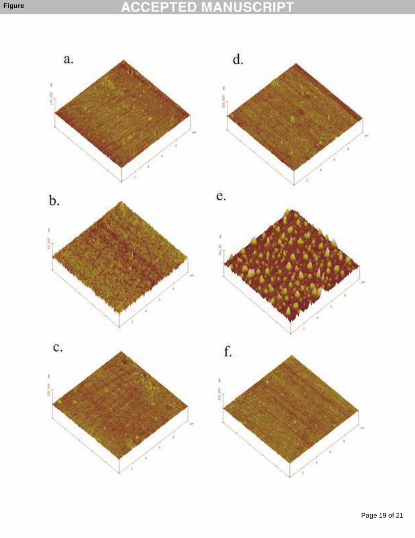
The sample surfaces were imaged using an AFM, from which growth mechanism and mean
surface roughness of each surface can be determined. The 3D AFM images are shown in Figure
5 for the different FeCo and NiFe films (bare-electrode (washed), Alq3 (as-grown) and Alq3
(washed)). It is immediately clear that all the films involving FeCo are extremely flat, with a rms
surface roughness of 1.004 nm for the FeCo (washed) film, while the FeCo/Alq3 (as-grown) rms
surface roughness was 1.932 nm and the FeCo/Alq3 (washed) rms surface roughness was 1.003
nm.
However, it is very clear from Fig 5e that the Alq3 grows in island formations on NiFe, which is
quite different from the growth mechanism on top of the FeCo electrode. For the NiFe (washed)
electrode the rms surface roughness was 0.858nm and the NiFe/Alq3 (washed) rms surface
roughness was 0.821nm, also very flat. We note that the Alq3 films were grown under nominally
identical conditions – the Alq3 growth rate for both was kept to between 0.1nm/s and 0.2nm/s,
and the growth was in the same chamber at the same vertical position, with the same substrate
stage rotation, from the same crucible (without being refilled between growths), with a load-lock
system used to perform the sample manipulation (such that the main-chamber was not vented to
atmosphere between growths). The substrates used for the ferromagnetic growth were from the
same batch and treated in the same way prior to growing the ferromagnets and the Alq3.
The growth mechanism of Alq3 can be altered by a number of different methods, including the
substrate wettability [27], deposition rate [28], and light condition [29]. The substrate wetting is
how well the Alq3 bonds to the surface, this includes a wetting layer, which is an amorphous
layer that forms, before the grain growth of the Alq3, it depends on the surface chemistry,
including the bonding and roughness [27]. It has also been found that a low evaporation rate
(<0.2nm/s) for Alq3 gives randomly oriented crystals with 10-30nm gaps between them, while
high evaporation rates (>0.4nm/s) gives a dense uniform film with no pinholes [28]. Growing
Alq3 in light (using a 100W tungsten filament lamp) and dark also influences the growth. For the
Alq3 films grown in light, islands were observed with surface roughness of 4.6nm, while growth
in the dark produced homogenous films with surface roughness of 2.1nm [29]. As the Alq3 films
were grown in the same conditions, it is likely that the surface energy of the NiFe electrode is
markedly different to the FeCo electrode, possible due to the presence of Ni or the lower oxide
coverage, which leads to the different growth mechanisms in Fig. 5 [27].
For neither electrode it is not possible to detect any individual molecules of Alq3 still attached to
the surface of the electrode after washing, which the XPS N(1s) and Al(2p) data show are
present. This is likely to be due to the resolution of the AFM not being sufficient to detect the
Alq3 molecules on the electrode surface, due to the molecules either being widely scattered
across the surface (i.e. not a continuous layer) or being in a continuous layer.

Page 7 of 21
Accep
ted
Man
uscr
ipt
The work function of the different surfaces were measured to compare the WF of NiFe and NiFe/
Alq3 (washed) surfaces to see if these is any difference due to the Alq3 being chemisorbed onto
the NiFe. For the NiFe surface the WF= 5.20 ± 0.01 eV, while for the NiFe/Alq3 surface before
washing the WF = 5.23 ± 0.01 eV and after washing the WF = 5.20 ± 0.01 eV. Thus there is no
difference in the WF between the NiFe surface and the NiFe/Alq3 (washed) surface, this could be
due to the measurement being done over a wide area (5mm2), leading to the NiFe dominating the
measurements, as there is a too small amount of Alq3 chemisorbed onto the surface of the NiFe
for the Kelvin Probe to detect. The WF measurements suggests that the Alq3 is not a continuous
layer on the surface after washing.
As there is evidence of a strong bonding between the Alq3 and the transition metal electrodes
from the XPS data (Figures 2-4), the work of Baurrad et al [14], suggests that the electronic
interface states should change with this bonding. From the SHIPS model, the first organic layer
on the electrode, changes the polarisation states, so changing the MR of the device. While Steil
et al [13], showed that the hybrid interface states exist due to the chemisorption of the Alq3 onto
the electrode, causing the molecular orbitals and metallic bands to interact. Thus to investigate
this change in the electronic interface states, the surface magnetisation of the magnetic electrodes
was measured using a MOKE magnetometer. This is because the magnetisation of a material is
related to the spin polarisation and density of states of the material, i.e the electronic states are
linked to the magnetisation. The principle of MOKE is that the polarised laser interacts with the
magnetisation within the thin film [30]. As the magnetic electrodes are transition metals, the
laser will only penetrate a certain distance, known as the skin depth into the magnetic film. The
skin depth of a material is given by:
2
2o
f
ρδπ μ
= (1)
Where ρ is the bulk resistivity of the material and f is the frequency of the light source. For the
MOKE set-up, the wavelength of the laser was 635nm, thus the frequency was 4.7x10¹⁴
Hz. The
bulk resistivity of FeCo is 79nΩ.m and NiFe is 69.3nΩ.m. Thus the skin depth of FeCo is 6.5nm
and NiFe is 6nm. This means that the majority of the magnetisation loop measured on the
MOKE magnetometer is from the surface magnetisation, rather than the magnetisation of the
whole film (t~40nm). Initial MOKE measurements on the first samples showed that there was no
difference in the magnetisation loops measured for the FeCo electrode and the FeCo/Alq3
sample. For the NiFe electrode and NiFe/Alq3 sample, a difference in the magnetisation loops
was measured. It was found that the NiFe/Alq3 magnetisation loop along the hard axis had a
larger coercive field compared to the NiFe electrode hard axis loop. To confirm that it was the
Alq3 causing the change in the magnetisation loop, and not other factors, such as a change in the
polariser or analyser angle, the alignment of the sample in the MOKE, a second set of NiFe/Alq3
samples were fabricated, with different thicknesses of NiFe. After the growth of the NiFe film,
the substrate was split in half, so that one half was kept as a NiFe electrode and the other half had
Page 8 of 21
Accep
ted
Man
uscr
ipt
Alq3 deposited on top. This allows further measurements of the NiFe electrode to be carried out
to make sure that any changes measured are due to the Alq3 rather than degradation. Also the
magnetisation loops of the NiFe electrode were measured before the Alq3 was deposited and then
after the Alq3 was deposited. Figure 6 shows the normalised magnetisation loops for NiFe
electrodes and the NiFe/Alq3 samples. It is observed that for all three NiFe thicknesses, the hard
axis hysteresis loop changes once the Alq3 has been deposited on top. This suggests that the
strong bonding at the interface between the NiFe and Alq3 does change the electronic states and
hence the surface magnetisation. It is observed that for all three samples, the coercive field of the
loops increases, with the Alq3 on top. The difference in coercive field for all three NiFe
thicknesses was ~0.25kA/m (Figure 7), which suggests the same influence has caused the change
in the surface magnetisation. From Figure 7, it is observed that the coercive field of NiFe linearly
decreases with thickness, and this decrease occurs for both the NiFe electrode and the NiFe/Alq3
sample. It is also noted in Figure 6, that the NiFe/Alq3 hard axis magnetisation loops are less
sharp compared to the NiFe electrode loops. The effect was probably not observed in FeCo, as
the coercive field of the FeCo electrode was 10kA/m, which is a factor 10 larger than the NiFe
electrode coercive field, so a change of ~0.25kA/m in the coercive field would be lost within the
error of the measurement. This is because a larger applied field (100kA/m) was required to
saturate the FeCo electrode, so the error on each field was ± 0.75kA/m, while a smaller applied
field (20kA/m) was required to saturate the NiFe electrode, leading to an error of ±0.2kA/m on
each field. Hence the difference is observed in NiFe as the coercive field of the NiFe is <1kA/m,
so a change of ~0.25kA/m is large enough to make a difference to the magnetisation measured.
As the MOKE magnetometer is a surface sensitive technique rather than a bulk technique, the
absolute magnetisation is not known, but the change in the surface magnetisation of the NiFe
electrode and the NiFe/Alq3 (washed) samples can be taken as the difference in the change in
light intensity when the film is measured. Thus doing this measurement for the NiFe electrode
the change in voltage was 0.0578V, while for the NiFe/Alq3 (washed) electrode the change in
voltage was 0.049V. This gives a ~15% decrease in the surface magnetisation due to the
chemisorptions of the Alq3 onto the NiFe electrode. As the skin depth is ~6nm, this suggests that
the Alq3 has chemisorbed into the top 1nm of the NiFe.
The XPS spectra and the MOKE data show that the Alq3 is strongly bonded to the bottom
electrode, and that this bonding changes the surface magnetisation. There are two possible ways
that the Alq3 could bond to the surface, the first is by chemically bonding onto the electrode
surface (chemisorption) via charge transfer, such as organic-metal oxide complexes and the
second is by physisorption via van der Waals forces [13, 24]. It is likely that the Alq3
chemisorbed onto the magnetic surfaces, as Alq3 was still present after cleaning, which shows
there was a strong bond between the Alq3 and the magnetic surface. This chemical bonding will
alter the density of states at the interface, by forming hybrid interface states [15], which will
change the spin polarisation and thus the surface magnetisation. This is the principle behind the

Page 9 of 21
Accep
ted
Man
uscr
ipt
SHIPS model given by Baurrad et al [14]. If the Alq3 physisorbed onto the surface of the
magnetic electrode, it changes the electronic structure by lowering the work function [13],
although this may not change the spin polarisation of the electrode. As van der Waals forces are
relatively weak, it is likely that cleaning the Alq3 layer with chloroform would remove the Alq3
from the surface. This would suggest that it is more likely that the Alq3 chemisorbed onto the
magnetic electrodes, as there was still a layer present after cleaning with chloroform.
This change in the surface magnetisation due to the adsorption of molecules into magnetic films,
has been studied for the adsorption of H onto ultrathin Co films [31], where they found that the
hydrogen forms strong H-Co bonds, which reduced the surface magnetisation when all the Co
atoms were bonded to H, but enhanced the surface magnetism, when there was partial H
coverage. Similarly, it has been shown that there is an electronic interaction between the C60 π
electrons and the Fe3O4 3d electrons, which lead to an induced magnetic moment in the
interfacial electronics states [32]. Density functional theory also predicted that benzene adsorbed
onto Fe(100) have a spin-polarisation induced onto it by the Fe(100) interface, whose sign is
determined by the distance of the benzene from the Fe surface [33]. As these studies demonstrate
that adsorption of small molecules into magnetic surfaces change the surface magnetisation and
the spin polarisation, this means the change in the magnetisation of the NiFe/Alq3 films can be
attributed to the Alq3 molecules chemisorption into the NiFe surface.
These previous measurements techniques such as x-ray absorption spectroscopy (XAS) and X-
ray magnetic circular dichroism (XMCD) have shown that the electronic properties are modified
by the chemisoption of organic molecules onto magnetic surfaces [32]. These technique probe
different element using high energy x-rays, and from the data it is possible to determine whether
interfacial magnetic moments are induced in the organic semiconductor and whether the spin
polarisation changes at the surface. They have shown that the spin polarisation is sensitive to the
magnetic and electronic structure of the interfaces. From our measurements we are able to state
the surface magnetisation changes with the chemisorptions of Alq3, and the surface
magnetisation reduces. This corresponds well with other measurements which have shown a
decrease in the magnetic moment with the addition of an organic semiconductor to the surface
[31, 32]. From this other work it can also be deduced that it is likely that the Alq3 is likely to
have an induced spin polarisation, due to the chemisorptions. It is also likely that the spin
polarisation does not change sign with the chemisorptions of Alq3 onto the transition electrode
surface, as from previous MR measurements [5,18], the MR measured without any interface
layers is always positive, as expected.
Conclusions
The XPS spectra and MOKE data show that the Alq3 strongly bonds to the surface of the
transition metal electrode. This bonding is likely to be due to chemisorptions of the Alq3 onto the
metal surface, as there is still Alq3 on the surface after washing. This chemisorption changes the
surface magnetisation of the electrode, which in principle will change the spin polarisation of the

Page 10 of 21
Accep
ted
Man
uscr
ipt
magnetic electrode, which is consistent with the SHIPS model. This means that the interface
between the bottom electrode and the organic semiconductor is very important in organic spin-
valves. The XPS spectra show that Alq3 bonds stronger to the FeCo electrodes compared to the
NiFe electrodes, which is probably due to the FeCo having a higher percentage oxide compared
to NiFe. This also could be related to the different growth mechanism of Alq3 on the FeCo and
NiFe. Indeed, it is worth noting that using NiFe as the bottom electrode in an Alq3 spin-valve is
unfavourable, as the Alq3 islands could yield make the magnetoresistance difficult to interpret or,
in the worst-case, the two electrodes shorting. The AFM and WF measurements demonstrate that
the Alq3 present on the NiFe surface after washing is not a continuous layer.
References
[1] L. Nuccio, M. Willis, L. Schulz, S. Fratini, F. Messina, M. D'Amico, F. L. Pratt, J. S. Lord, I.
McKenzie, M. Loth, B. Purushothaman, J. Anthony, M. Heeney, R. M. Wilson, I. Hernandez, M.
Cannas, K. Sedlak, T. Kreouzis, W. P. Gillin, C. Bernhard, and A. J. Drew, Importance of Spin-
Orbit Interaction for the Electron Spin Relaxation in Organic Semiconductors, Physical Review
Letters, 110, (2013) 216602.
[2] Z. H. Xiong, D. Wu, Z. Valy Vardeny, and J. Shi, Giant magnetoresistance in organic spin-
valves, Nature, 427, (2004), 821 - 824.
[3] V. A. Dediu, L. E. Hueso, I. Bergenti, and C. Taliani, Spin routes in organic semiconductors,
Nature Materials, 8, (2009), 707 - 716.
[4] F. C. Wang, Z. H. Xiong, D. Wu, J. Shi, and Z. V. Vardeny, Organic Spintronics: The case of
Fe/Alq3/Co spin-valve devices, Synthetic Metals, 155, (2005), 172-175.
[5] D. Dhandapani, N. A. Morley, M. R. J. Gibbs, T. Kreouzis, P. Shakya, P. Desai, and W. P.
Gillin, The Effect of Injection Layers on a Room Temperature Organic Spin valve, IEEE
Transaction on Magnetics, 46, (2010), 1307 - 1310.
[6] H. Vinzelberg, J. Schumann, D. Elefant, R. B. Gangineni, J. Thomas, and B. Buchner, Low
temperature tunneling magnetoresistance on (La, Sr)MnO3/Co junctions with organic spacer
layers, Journal of Applied Physics, 103, (2008), 093720.
[7] S. Majumdar, H. S. Majumdar, R. Laiho, and R. Osterbacka, Comparing small molecules and
polymer for future organic spin-valves, Journal of Alloys and Compounds, 423, (2006), 169 -
171.
[8] N. A. Morley, A. Rao, D. Dhandapani, M. R. J. Gibbs, M. Grell, and T. Richardson, Room
temperature organic spintronics, Journal of Applied Physics, 103, (2008), 07F306.
[9] J. H. Shim, K. V. Raman, Y. J. Park, T. S. Santos, G. X. Miao, B. Satpati, and J. S. Moodera,
Large spin diffusion length in an amorphous organic semiconductor, Physical Review Letters,
100, (2008), 226603.
[10] R. Lin, F. Wang, J. Rybicki, M. Wohlgenannt, and K. A. Hutchinson, Distinguishing
between tunneling and injection regimes of ferromagnet/organic semiconductor/ferromagnet
junctions, Physical Review B, 81, (2010), 195214.

Page 11 of 21
Accep
ted
Man
uscr
ipt
[11] V. Dediu, L. E. Hueso, I. Bergenti, A. Riminucci, F. Borgatti, P. Graziosi, C. Newby, F.
Casoli, M. P. De Jonge, C. Taliani and Y. Zhan, Room temperature spintronics effects in Alq3-
based hybrid devices Physical Review B, 78, (2008), 115203
[12] S. Mooser, J. F. K. Cooper, K. K. Banger, J. Wunderlich and H. Sirringhaus, Spin injection
and transport in a solution-processed organic semiconductor at room temperature. Physical
Review B, 85, (2012), 235202
[13] A. J. Drew, G. Szulczewski, L. Nuccio, and W. P. Gillin, The role of interfaces in organic
spin valves revealed through spectroscopic and transport measurements, Phys. Stat. Sol. B, 249,
(2012) 9-17.
[14] C. Barraud, P. Seneor, R. Mattana, S. Fusil, K. Bouzehouane, C. Deramlot, P. Graziosi, L.
E. Hueso, I. Bergenti, V. A. Dediu, F. Petroff and A. Fert, Unravelling the role of the interface
for spin injection into organic semiconductors Nature Physics, 6, (2010), 615
[15] S. Steil, N. Grosmann, M. Laux, A. Ruffing, D. Steil, M. Wiesenmayer, S. Mathias, O. L. A.
Monti, M. Cinchetti, and M. Aeschlimann, Spin-dependent trapping of electrons at spinterfaces,
Nature Physics, 9, (2013), 242 - 247.
[16] S. Majumdar, R. Laiho, P. Laukkanen, I. J. Vayrynen, H. S. Majumdar and R. Osterbacka,
Application of regioregular polythiophene in spintronic devices: Effect of interface Applied
Physics Letters, 89, (2006), 122114
[17] N. A. Morley, H. R. H. AlQahtani, M. H. Hodges, M. R. J. Gibbs, M. Grell, V. A. Dediu
and D. J. Morgan, Study of polymer-magnetic electrode interfaces using XPS. Applied Surface
Science, 265, (2013), 570 - 577
[18] L. Schulz, L. Nuccio, M. Willis, P. Desai, P. Shakya, T. Kreouzis, V. K. Malik, C.
Bernhard, F. L. Platt, N. A. Morley, A. Suter, G. J. Nieuwenhuys, T. Prokscha, E. Morenzoni,
W. P. Gillin and A. J. Drew, Engineering spin propagation across a hybrid organic-inorganic
interface with polar molecules Nature Materials, 10, (2011), 39-44
[19] G. Szulczewski, J. Brauer, E. Ellingsworth, J. Kreil, H. Ambaye and V. Lauter, Electronic
and structural characterisation of LiF tunnel barriers in organic spin-valve structures. Journal of
Applied Physics, 109, (2011), 07C509
[20] http:/www.casaxps.com/
[21] N. A. Morley, A. Javed and M. R. J. Gibbs, Structural and magnetic properties of thin Fe-
Ga films. Journal of Applied Physics, 105, (2009), 07A912
[22] N. A. Morley, D. Dhandapani, A. Rao, H. Al Qahtai, M. R. J. Gibbs, M. Grell, D. Eastwood
and B. K. Tanner, Polymeric spin-valves at room temperature, Synthetic Metals, 161, (2011),
558-562
[23] H. Li, F. Zhang and S. Liu, Surface and interface state analysis of the TPD/Alq3 using X-
ray photoelectron spectroscopy (XPS) and atomic force microscopy (AFM). Applied Surface
Science, 225, (2004), 162-169
[24] T. P. Nguyen, J. Ip, P. Jolinat and P. Destruel, XPS and sputtering study of the
Alq3/electrodes interfaces in organic light emitting diodes. Applied Surface Science, 172,
(2001), 75-83

Page 12 of 21
Accep
ted
Man
uscr
ipt
[25] L. Yan, M. G. Mason, C. W. Tang and Y. L. Gao, Photoemission study of energy alignment
at the metal/Alq(3) interfaces, Applied Surface Science, 175, (2001), 412-418
[26] J. Lee, Y. Park, S. K. Lee, E-J. Cho, D. Y. Kim, H. Y. Chu, H. Lee, L-M. Do and T. Zyung,
Tris-(8-hydroxyquinoline)aluminium-based organic light-emitting devices with Al/CaF2
cathode: Performance enhancement and interface electronic structures, Applied Physics Letters,
80, (2002), 3123 - 3125
[27] S. Tsoi, B. Szeto, M. D. Fleischauer, J. G. C. Veinot and M.J. Brett, Control of Alq3 wetting
layer thickness via substrate surface functionalisation, Langmuir, 23, (2007), 6497-6500
[28] H. Mu, H. Shen and D. Klotzkin, Dependence of film morphology on deposition rate in
ITO/TPD/Alq3/Al organic luminescent diodes, Solid-state Electronics, 48, (2004), 2085-2088
[29] F. Zhang, Z. Xu, D. Zhao, S. Zhao, W, Jiang, G. Yuan, D. Song, Y. Wang and X. Xu,
Influence of evaporation conditions of Alq3 on the performance of organic light emitting diodes,
J. Phys. D: Appl. Phys, 40, (2007), 4485-4488
[30] D. A. Allwood, G Xiong, M. D. Cooke, and R. P. Cowburn, Magneto-optical Kerr effect
analysis of magnetic nanostructures, Journal of Physics D: Applied Physics, 36, (2003), 2175 -
2182.
[31] S. Gallego, N. Sanchez, S. Martin, and M.C. Munoz, Reversible enhancement of the
magnetisation of ultrathin Co films by H adsorption, Physical Review B, 82, (2010), 085414
[32] P. K. J. Wong, W. Zhang, K. Wang, G. van der Laan, Y. Xu, W. G. van der Wirl and M. P.
de Jong, Electronic and magnetic structure of C60/Fe3O4(001): a hybrid interface for organic
spintronics, J. Mater. Chem. C, 1, (2013), 1197
[33] S. Goumri-Saod, M. B. Kanoun, A. Manchon and U. Schwingenschlogl, Spin-polarisation
reversal at the interface between benzene and Fe(100) Journal of Applied Physics, 113, (2013),
013905
Acknowledgements
NAM would like to thank Miss D Bussey at the University of Sheffield for taking the AFM data
and Prof Mike Gibbs at the University of Sheffield for useful discussions. The XPS
measurements were taken under the EPSRC facilities access grant no EP/F019823/1. AJD and
HZ would like to acknowledge financial support from the EU Framework Programme 7 (FP7)
Project NMP3-SL-2011-263104 “HINTS” and the Chinese Scholarship Council (CSC).
Page 13 of 21
Accep
ted
Man
uscr
ipt
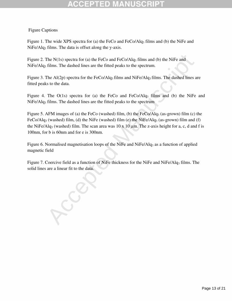
Figure Captions
Figure 1. The wide XPS spectra for (a) the FeCo and FeCo/Alq3 films and (b) the NiFe and
NiFe/Alq3 films. The data is offset along the y-axis.
Figure 2. The N(1s) spectra for (a) the FeCo and FeCo/Alq3 films and (b) the NiFe and
NiFe/Alq3 films. The dashed lines are the fitted peaks to the spectrum.
Figure 3. The Al(2p) spectra for the FeCo/Alq3 films and NiFe/Alq3 films. The dashed lines are
fitted peaks to the data.
Figure 4. The O(1s) spectra for (a) the FeCo and FeCo/Alq3 films and (b) the NiFe and
NiFe/Alq3 films. The dashed lines are the fitted peaks to the spectrum
Figure 5. AFM images of (a) the FeCo (washed) film, (b) the FeCo/Alq3 (as-grown) film (c) the
FeCo/Alq3 (washed) film, (d) the NiFe (washed) film (e) the NiFe/Alq3 (as-grown) film and (f)
the NiFe/Alq3 (washed) film. The scan area was 10 x 10 μm. The z-axis height for a, c, d and f is
100nm, for b is 60nm and for e is 300nm.
Figure 6. Normalised magnetisation loops of the NiFe and NiFe/Alq3 as a function of applied
magnetic field
Figure 7. Coercive field as a function of NiFe thickness for the NiFe and NiFe/Alq3 films. The
solid lines are a linear fit to the data.

Page 14 of 21
Accep
ted
Man
uscr
ipt
Highlights
Alq3 chemisorbs onto magnetic transition metal surfaces
Alq3 changes the surface magnetisation of the NiFe film
Alq3 chemisorbs stronger onto the oxide rich FeCo surface

Page 15 of 21
Accep
ted
Man
uscr
ipt
Figure

Page 16 of 21
Accep
ted
Man
uscr
ipt
Figure

Page 17 of 21
Accep
ted
Man
uscr
ipt
Figure

Page 18 of 21
Accep
ted
Man
uscr
ipt
Figure
Page 19 of 21
Accep
ted
Man
uscr
ipt
Figure

Page 20 of 21
Accep
ted
Man
uscr
ipt
Figure

Page 21 of 21
Accep
ted
Man
uscr
ipt
Figure