pravinprabhu.files.wordpress.com file · Web viewWhat information should be available in an...
23
Source: http://nptel.ac.in/courses/112103019/1 Prof. P.S. Robi, IIT Guwahati National Programme on Technology Enhanced Learning (NPTEL) - Phase II Indian Institute of Technology Guwahati Guwahati - 781039, Assam, India Introduction Drawing is the Graphical means of expression of technical details without the barrier of a language. Engineering Drawing is the Universal Language for Engineers Communication in engineering is necessary for effectively transferring one’s ideas to others. While communicating, we use our memory to remember objects, sense organs to perceive objects and mind to imagine objects. Our perception are coloured or modified by our past experiences. We see things around us, perceive the objects and identify them by their names. Later, when we hear these names we can remember these items easily and imagine various features like the shape, size, color, functions etc,. e.g. if I say that a particular object is having the shape of a cricket bat, it is easy for a high school student to imagine the shape of the object since he has seen a cricket bat and has perceived the object. If I say that a particular object looks like the Dendrite formed during solidification of a metal, then it is difficult for the same student to imagine, since he has not seen a dendrite. His question will “how do a dendrite look like?” when we say that dendrite means tree-like structure, his imagination can go to different types of trees, but still he may not have a clear picture of the dendrite. If we show him a picture of a dendrite, he can very easily perceive that object. One picture/drawing is equivalent to several sentences. It is not easy for anyone to make another person understand somebody’s face just by explaining the features. Even if several sentences are used to explain the features of the face, words it would be difficult for the listener to perceive the image of the face. However, if you show a sketch or a photograph of the person, all these sentences can be saved. i.e., We grasp information easily if it is illustrated with diagrams, sketches, pictures, etc. Engineering drawing Drawings help us in developing our thoughts and ideas in to a final product.
Transcript of pravinprabhu.files.wordpress.com file · Web viewWhat information should be available in an...

Source:http://nptel.ac.in/courses/112103019/1Prof. P.S. Robi, IIT GuwahatiNational Programme on Technology Enhanced Learning (NPTEL) - Phase IIIndian Institute of Technology GuwahatiGuwahati - 781039, Assam, India
IntroductionDrawing is the Graphical means of expression of technical details without the barrier of a language. Engineering Drawing is the Universal Language for Engineers
Communication in engineering is necessary for effectively transferring one’s ideas to others. While communicating, we use our memory to remember objects, sense organs to perceive objects and mind to imagine objects. Our perception are coloured or modified by our past experiences.
We see things around us, perceive the objects and identify them by their names. Later, when we hear these names we can remember these items easily and imagine various features like the shape, size, color, functions etc,. e.g. if I say that a particular object is having the shape of a cricket bat, it is easy for a high school student to imagine the shape of the object since he has seen a cricket bat and has perceived the object. If I say that a particular object looks like the Dendrite formed during solidification of a metal, then it is difficult for the same student to imagine, since he has not seen a dendrite. His question will “how do a dendrite look like?” when we say that dendrite means tree-like structure, his imagination can go to different types of trees, but still he may not have a clear picture of the dendrite. If we show him a picture of a dendrite, he can very easily perceive that object.
One picture/drawing is equivalent to several sentences. It is not easy for anyone to make another person understand somebody’s face just by explaining the features. Even if several sentences are used to explain the features of the face, words it would be difficult for the listener to perceive the image of the face. However, if you show a sketch or a photograph of the person, all these sentences can be saved. i.e., We grasp information easily if it is illustrated with diagrams, sketches, pictures, etc.
Engineering drawingDrawings help us in developing our thoughts and ideas in to a final product. Drawings are also necessary for engineering industries since they are required and are being used at various stages of development of an engineering product. Engineering drawing is completely different from artistic drawing, which are used to express aesthetic, philosophical, and abstract ideas. In an industry, these drawings help both the technical as well as commercial staffs at various stages like:
conceptual stage design stage modification stage prototype development stage process and production planning production inspection marketing Servicing and maintenance, etc.

What information should be available in an engineering drawing?A perfect engineering drawing should have the following information:
Shape of an object Exact Sizes and tolerances of various parts of the object The finish of the product The details of materials The company’s name Catalogue no of the product Date on which the drawing was made The person who made the drawing
Drawings are the road maps which show how to manufacture products and structures. No industrial level construction/manufacturing of any (man-made) engineering objects is possible without engineering drawing.
What will you learn from this course?In this course you will learn how to communicate technical information by:Visualization – the ability to mentally understand visual information.Graphics theory – geometry and projection techniques used for preparation of drawings.Use of standards – set of rules for preparation of technical drawings.Use of conventions – commonly accepted practices in technical drawings.Tools – devices used to create technical drawings and models.Applications – the various uses for technical drawings. Developing an engineering drawing can be either by manual drawing or by computer graphics
Computer has a major impact on the methods used to design and create technical drawings. The tools are Computer aided design and drafting (CADD).Design and drafting on computer are cheap and less time consuming. Then why we go for manual drawing?
Computer cannot replace the drafting board and equipment as a learning tool. In schools, students are not allowed to use calculators up to calss 12. During this period if they use calculators from class 1, they will not improve their mathematical skills. After calss 12, i.e., once they have learned the basics of mathematics, they are allowed to use calculators and computers. Hence before use of the drafting software, their fundamentals regarding drawing should be clear. If basic fundamentals are clear, better use can be made of the power of the software. To be an expert in technical drawing, this first course on Engineering (manual) drawing is the first step.
DRAWING INSTRUMENTS AND ACCESSORIESThe following set of instruments are required for ensuring perfection in manual drawing:
1. Drawing board
Drawing board is made of soft wooden platens. Almost perfect planning of the working surface of the drawing board is to be ensured. A strip of hard ebony edge is fitted up in a groove on the shorter edge of the board and perfectly lined to provide the guide for the T-square. The standard sizes of the drawing board is shown in Table 1.1 below. D2 size of drawing board is normally recommended for the First year Engineering students.

2. Drawing Sheet
Drawing sheet is the medium on which drawings are prepared by means of pencils or pen. Drawing sheets are available in standard sizes as shown in Table 1.2. A standard A0 size sheet is the one with an area of 1 m-2 and having dimensions of 1189 x 841. Each higher number sheet (A1, A2, A3, etc. in order) is half the size of the immediately lower numbered sheet. For drawing practice for first year engineering students A2 size is the preferred drawing sheet. The recommended sizes obtained for various drawing sheets are shown in figure 1

Figure 1. recommended sizes obtained for various drawing sheets
3. Mini-drafter
This is a device used to draw parallel or inclined lines very effectively with ease. This is mounted on the top left corner of the drawing board by means of a clamping mechanism which is an integral part of the device. Figure 2 shows the photograph of a typical college level mini drafter.An L-shaped scale which is graduated in millimeters acts as the working edge of the mini-drafter. The L-Shaped scale also has a degree scale for angle measurement. The working edge can be moved to any desired location on the drawing board.
Procedure for clamping the mini-drafter Set the protractor head with reference mark indexing zero degree, then fix the clamp of the mini-drafter at the top left corner either along the top horizontal edge of the board or along the left vertical edge of the board. With the drawing sheet placed underneath the scales of the mini-drafter, fix the drawing sheet to the drawing board with the scales of the mini- drafter aligned either with the vertical or the horizontal borderlines of the drawing sheet.

4. Set squares
Set squares are a set of 45° set square and 30°-60° set-square, as shown in figure 3.They are used in conjunction with each other and with T-square to draw parallel, inclined and perpendicular lines. They are made of transparent acrylic. Each is having beveled edges with engraved mm or inch marking. The 45° set square generally has a protractor where as the 30°-60° set-square includes French curves.
5. Compasses
These are used to draw arcs or circles. Generally two sizes of compasses: one large compass and the other a small spring bow compass are commonly found. Each compass consist of a needle point and a pencil point. For drawing very large radius arcs, the pencil point leg can be removed from the knee joint and a lengthening bar can be inserted to increase the radius of the arc. Figure 4 shows the photograph of a compass.Figure 4 shows the photograph of a compass.

Figure 4. Photograph of a compass
6. Divider
Dividers are used to transfer lengths to the drawings either from scales or from the drawing itself. Similar to the compasses, two sizes of dividers are used in technical drawings. One large divider and the other small spring bow divider.
7. Pencils / lead sticks/ pencil sharpener / eraser/etc:
The primary tool used in technical drawings is the pencil or lead sticks. Generally for technical drawings, the three grades of pencil used is HB, H and 2H . For different purposes, different grades of pencils are used. Pencil sharpener is is used to mend the pencils. Eraser is used to erase the unnecessary part of the pencil drawing.
8. French curve/Flexible curve
French curve is free form template make of acrylic and is used to draw a smooth curve passing through a number of points. The outer profile of the French curve is adjusted such the smooth curve passes through more than three points and a curve passing through these lines are drawn. The next part of the curve is then drawn by using the next three points in addition to the last two points of the previous curve.A typical French curve is shown in figure 6. A flexible curve is consists of a flexible, generally made of metallic wire coated with a thick rubber material. This can be bend in to any shape so that its working edge can be matched with a number of points and a smooth curve can be .

Figure 6. A typical French Curve.
Layout of drawing sheets
Any engineering drawing has to follow a standard format. The drawing sheet consist of drawing space, title block and sufficient margins. After fixing the drawing sheet on the drawing board, margins should be drawn. The layout should facilitate quick reading of important particulars. Drawings are prepared at various locations and shared and quick references should be located easily. A typical drawing sheet is shown in figure 4 and consist of the following:
a. Borders – space left all around in between the trimmed edges of the sheet. A minimum of 10 mm
b. Filling margin – 20 mm minimum on left hand side with border included. This is provided for taking perforations.
c. Grid reference system – For all sizes of drawing sheets for easy location of drawing within the frame. The length and the width of the frames are divided into even number of divisions. Number of divisions for a particular sheet depends on complexity of the drawing. The length of the grids lies between 25 mm to 75mm depending on the Drawing sheet size. The grids along vertical edges are named by capital letters where as grids along the horizontal edges are by numerals. Numbering and lettering start from the corner of the sheet opposite to the title box and are repeated on the opposite sides. The numbers and letters are written upright. Repetition of letters or numbers like AA, BB, etc. are practiced in case they exceed that of the alphabets.
Figure 7. Typical drawing layout showing the margins, location of title block and grids.
d. d.Title box – An important feature which is a must in every drawing sheet. The title box is drawn at the bottom right hand corner of every drawing sheet and provides technical and administrative details regarding the drawing/component. Though there are various dimensions for the title box, for Engineering students it is advisable to use a title box of size 170 mm x 65 mm.
e. The title box is divided in to two zones: (a) part identification zone and (b) additional information zone. In the part identification zone, information like the component identification number , name of the part, the legal owner of the drawing (i.e. the name of firm/component/etc will be highlighted where as in the additional information zone, technical information like symbols indicating the system of projection, scale of drawing, method of indicating surface texture, geometric tolerances, etc. will be highlighted.

Layout of a drawing sheet Every drawing sheet is to follow a particular layout. As a standard practice sufficient margins are to be provided on all sides of the drawingsheet. The drawing sheet should have drawing space and title page. A typical layout of a drawing sheet is shown in the figure below:
Figure 1. A typical layout of a drawing sheet.
Borders – A minimum of 10 mm space left all around in between the trimmed edges of the sheet.
Filing margin – Minimum 20 mm space left on the left hand side with border included. This provided for taking perforations .
Grid reference system – This is provided on all sizes of industrial drawing sheets for easy location of drawing within the frame. The length and the width of the frames are divided into even number of divisions and labeled using numerals or capital letters. Number of divisions for a particular sheet depends on complexity of the drawing. The grids along the horizontal edges are labeled in numerals where as grids along vertical edges are labeled using capital letters. The length of each grids can be between 25 mm and 75 mm. Numbering and lettering start from the corner of the sheet opposite to the title box and are repeated on the opposite sides. they are written upright. Repetition of letters or numbers like AA, BB, etc., if they exceed that of the alphabets. For first year engineering students grid references need not be followed.
Title box – An important feature on every drawing sheet. This is located at the bottom right hand corner of every sheet and provides the technical and administrative details of the drawing. The title box is divided into two zones
a. Identification zone : In this zone the details like the identification number or part number, Title of the drawing, legal owner of the drawing, etc. are to be mentioned.
b. Additional information zone : Here indicative items lime symbols indicting the system of projection, scale used, etc., the technical items lime method of surface texture, tolerances, etc., and other administrative items are to be mentioned.
Layout of the title box recommended for Engineering Drawing CourseThe title box shown in figure 2 can be used for the engineering Drawing Course.

Figure 2. A typical title box recommended for Engineering students.
Lettering Lettering is used for writing of titles, sub-titles, dimensions, scales and other details on a drawing. Typical lettering features used for engineering drawing is shown in figure 3. The following rules are to be followed in lettering. The letter sizes generally recommended for various items are shown in Table 1.
Essential features of lettering – legibility, uniformity, ease, rapidity, and suitability for microfilming/photocopying/any other photographic processes
No ornamental and embellishing style of letter Plain letters and numerals which are clearly distinguishable from each other in order
to avoid any confusion even in case of slight mutilations
The Indian standard followed for lettering is BIS: 9609
Single stroke lettering for use in engineering drawing – width of the stem of the letters and numerals will be uniformly thick equal to thickness of lines produced by the tip of the pencil.
Single stroke does not mean – entire letter written without lifting the pencil/pen
Lettering types generally used for creating a drawing are
Lettering A – Height of the capital letter is divided into 14 equal parts Lettering B – Height of the capital letter is divided into 10 equal parts
Table 2 and Table 3 indicates the specifications for Type A and Type B letters.

Figure 3. Typical lettering features.
Heights of Letters and Numerals
1. Height of the capital letters is equal to the height of the numerals used in dimensioning
2. Height of letters and numerals – different for different purposes
Table 1 The letter sizes recommended for various items
Table 2. Specifications of A -Type Lettering

Table 3. Specifications of B -Type Lettering
How to begin your drawing? To start with the preparation of a drawing the procedure mentioned below may be followed:
Clean the drawing board and all the drawing instruments using duster. Fix the drawing sheet on the drawing board. Fix the mini-drafter in a convenient position. Draw border lines using HB pencil.. Complete the title box using HB pencil . Plan spacing of drawings b/n two problems/views beforehand. Print the problem number on the left top and then commence the drawing work.
Keeping the drawing clean is a must

Never sharpen pencils over drawing. Clean pencil point with a soft cloth after sharpening. Keep drawing instruments clean. Rest hands on drawing instruments as much as possible – to avoid smearing the
graphite on the drawing. When darkening lines – try to work from the top of the drawing to the bottom, and
from left to the right across the drawing. Use brush to remove eraser particles. Never use hands. Always use appropriate drawing pencils.
Lines Lines is one important aspect of technical drawing. Lines are always used to construct meaningful drawings. Various types of lines are used to construct drawing, each line used in some specific sense. Lines are drawn following standard conventions mentioned in BIS (SP46:2003). A line may be curved, straight, continuous, segmented. It may be drawn as thin or thick. A few basic types of lines widely used in drawings are shown in Table 1.
Table 1. Types of letters used in engineering drawing.
Line Strokes Line strokes refer to the directions of drawing straight and curved lines. The standards for lines is given in BIS : SP-46, 2003 Vertical and inclined lines are drawn from top to bottom, horizontal lines are drawn from left to right. Curved lines are drawn from left to right or top to bottom. The direction of strokes are illustrated in figure 1.

Figure 1. The line strokes for drawing straight and curved lines.
Conventions used in lines
International systems of units (SI) – which is based on the meter. Millimeter (mm) - The common SI unit of measure on engineering drawing. Individual identification of linear units is not required if all dimensions on a drawing
are in the same unit (mm). The drawing should contain a note: ALL DIMENSIONS ARE IN MM. (Bottom left corner
outside the title box)
Typical figures showing various lines used in the construction of engineering drawing is shown in figure 2.
Figure 2 Typical figure showing various lines used engineering drawing
A typical use of various lines in an engineering drawing is shown in figure below:

Dimensioning The size and other details of the object essential for its construction and function, using lines, numerals, symbols, notes, etc are required to be indicated in a drawing by proper dimensioning. These dimensions indicated should be those that are essential for the production, inspection and functioning of the object and should be mistaken as those that are required to make the drawing of an object. The dimensions are written either above the dimension lines or inserted at the middle by breaking the dimension lines.
Normally two types of dimensioning system exist. i.e. Aligned system and the unidirectional system.These are shown in figure 3.
In the aligned system the dimensions are placed perpendicular to the dimension line in such a way that it may be read from bottom edge or right hand edge of the drawing sheet. The horizontal and inclined dimension can be read from the bottom where as all the vertical dimensions can be read from the right hand side of the drawing sheet. In the unidirectional system, the dimensions are so oriented such that they can be read from the bottom of the drawing.

Figure 3. The aligned system and unidirectional system of dimensioning.
Rules to be followed for dimensioning. Refer figure 4.
Each feature is dimensioned and positioned only once. Each feature is dimensioned and positioned where its shape shows. Size dimensions – give the size of the component. Every solid has three dimensions, each of the geometric shapes making up the
object must have its height, width, and depth indicated in the dimensioning.

Figure 4. typical dimension lines
Dimensioning consists of the following:
A thin, solid line that shows the extent and direction of a dimension. Dimension lines are broken for insertion of the dimension numbers
Should be placed at least 10 mm away from the outline and all other parallel dimensions should be at least 6 mm apart, or more, if space permits
The important elements of dimensioning consists of extension lines, leader line, arrows and dimensions.
Extension line – a thin, solid line perpendicular to a dimension line, indicating which feature is associated with the dimension. There should be a visible gap of 1.5 mm between the feature’s corners and the end of the extension line.Figure 5 shows extension lines.Leader line A thin, solid line used to indicate the feature with which a dimension, note, or symbol is associated. Generally this is a straight line drawn at an angle that is neither horizontal nor vertical. Leader line is terminated with an arrow touching the part or detail. On the end opposite the arrow, the leader line will have a short, horizontal shoulder. Text is extended from this shoulder such that the text height is centered with the shoulder line
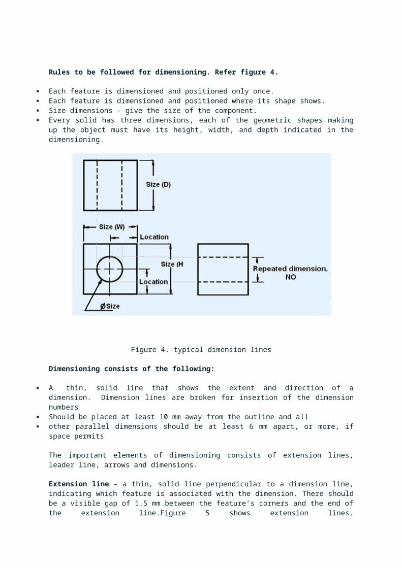
Figure 5. showing extension lines
Arrows – 3 mm wide and should be 1/3rd as wide as they are long - symbols placed at the end of dimension lines to show the limits of the dimension. Arrows are uniform in size and style, regardless of the size of the drawing.Various types of arrows used for dimensioning is shown in figure 6.
Figure 6.Various types of arrows used for dimensioning
e specification of dimension lines are shown in figure 7.

Figure 7 showing the specification of dimension lines.
Dimensioning of angles: The normal convention for dimensioning of angles are illustrated in figure 8.
Figure 8 conventions used for dimensioning angles.
Few examples during dimensioning of solids are shown below:
Prism – This is the most common shape and requires three dimensions. Two dimensions shown on the principal view and the third dimension on the other view.

Cylinder – Cylinder is the second most common shape. It requires two dimensions: diameter and length, both shown preferably on the rectangular view.
Cone – requires two dimensions – diameter of the base and altitude on the same view and length. Both shown on the rectangular view is preferred.

Right pyramids – requires three dimensions – dimensions of the base and altitude.
Spheres – requires only one dimension. i.e. diameter. However in case of extra features, those dimensions are required to be provided.

RULES OF DIMENSIONING
1. Between any two extension lines, there must be one and only one dimension line bearing one dimension.
2. As far as possible, all the dimensions should be placed outside the views. Inside dimensions are preferred only if they are clearer and more easily readable.
3. All the dimensions on a drawing must be shown using either Aligned System or Unidirectional System. In no case should, the two systems be mixed on the same drawing.
4. The same unit of length should be used for all the dimensions on a drawing. The unit should not be written after each dimension, but a note mentioning the unit should be placed below the drawing.
5. Dimension lines should not cross each other. Dimension lines should also not cross any other lines of the object.
6. All dimensions must be given.7. Each dimension should be given only once. No dimension should be redundant.8. Do not use an outline or a centre line as a dimension line. A centre line may be
extended to serve as an extension line.9. Avoid dimensioning hidden lines.10.For dimensions in series, adopt any one of the following ways.
i. Chain dimensioning (Continuous dimensioning) All the dimensions are aligned in such a way that an arrowhead of one dimension touches tip-to-tip the arrowhead of the adjacent dimension. The overall dimension is placed outside the other smaller dimensions.
ii. Parallel dimensioning (Progressive dimensioning) All the dimensions are shown from a common reference line. Obviously, all these dimensions share a common extension line. This method is adopted when dimensions have to be established from a particular datum surface
iii. Combined dimensioning. When both the methods, i.e., chain dimensioning and parallel dimensioning are used on the same drawing, the method of dimensioning is called combined dimensioning.