· Web viewThe nutating disc shall be equipped with a synthetic polymer thrust roller located...
42
January 2007 DECATUR COUNTY CON STR UCT ION & DEV ELO PME NT STANDARDS MANUAL SECTION 02660 WATER MAI Table of Contents S e c t i o n S u b j e c t Page 1 . 0 0 Gener al 3 1 . 0 1 Descr iptio n 3 1 . 0 2 Relat ed Secti ons 3 2 . Mater ial 3
Transcript of · Web viewThe nutating disc shall be equipped with a synthetic polymer thrust roller located...

January 2007
DECATUR COUNTYCONSTRUCTION & DEVELOPMENTSTANDARDS MANUAL
SECTION 02660WATER MAINS
Table of Contents
Section
Subject Page
1.00 General 31.01
Description 3
1.02
Related Sections 3
2.00
Material 3
2.01 Pipe 32.02 Joints 32. Restrai 3

03
nt Devices
2.04
Certificates 4
2.05 Fitting 42.06
Adapters 4
2.07 Gaskets 42.08
Gate Valves 5
2.09
Valve Box 5
2.10
Check Valves 6
2.11
Tapping Sleeve 6
2.12
Air and Vacuum Valves 6
2.13
Air and Vacuum Chambers 6
2.14
Meter Yoke 8
2.15
Meter Pit 8
2.16
Meter Box Cover 9
2.17
Fire Hydrant 9
2.18
Flush Hydrant 9
3.00
Execution 10
3. Pipe 10

01
Installation
3.02
Residentual Meters 11
3.03
Meter Pits 11
3.04
Excavation and Backfill 11
3.05
Restoration 11
3.06
Hydrostatic Testing 12
3.07
Sterilization of Water Main 12
Decatur County StandardsSection 02660
Page 1January 2007
3.08
Chlorination Procedure When Cutting Existing Main 13
LIST OF DRAWINGS
Title Drawing No.Water Main W-1Joint Restraint W-2

Thrust Block W-3Anchor W-4Fire Hydrant W-5Valve & Valve Box W-6
Decatur County StandardsSection 02660
Page 2

January 2007
1.0 General
1.1 Description
A. The work under this section shall consist of furnishing and installation of all water mains, piping, fittings, valves, and appurtenances necessary to complete work.
1.2 Related Work Described Elsewhere
A. Earthwork for Utilities Section 02222
B. Paving and Surfacing Section 02500
C. Landscaping for Utilities Section 02902
1.3 Definitions
A. ANSI – American National Standards Institute
B. ASTM – American Society for Testing & Materials
C. AWWA – American Water Works Association
2.0 Materials
2.1 Pipe
A. Ductile Iron (DI), ANSI/AWWA C15/A21.5, ANSI/AWWA C104/A21.4, CementLined.
B. Polyvinyl Chloride (PVC), AWWA C900, DR-18 Class 150, NSF.
C. Service Lines 2" and smaller – copper, Type "K", Soft Tube: STM B88.
2.2 Joints
A. PVC Pipe Joints shall be push-on type in compliance with the requirements for ASTM D-3139 and ANSI/AWWA C900.
B. Ductile Iron - All exposed ductile iron pipe shall have flanged fittings in accordance with ANSI/AWWA C110/A21.10
2.3 Restraint Devices
A.Restraint to prevent axial separation shall be equal to EBAA Iron, Inc Series 4800.
Decatur County StandardsSection 02660
Page 3

January 2007
B. The restraint joining shall meet the applicable requirements of AWWA C219, ANSI/AWWA C111/A21.11 and ASTM D2000.
2.4 Certificates
A. Manufacturer's certification, certifying that the material was manufactured and tested in accordance with this specification shall be provided
2.5 Fittings
A. Fitting shall be ductile iron and meet the requirements of ANSI/AWWA C110. Design and manufacturer fittings for a pressure rating of 150 psi.
B. Fitting joints shall be mechanical joints. Mechanical joints shall meet the requirements of ANSI/AWWA C111/A21.11.
2.6 Adapters
A. Adapters from polyvinyl chloride water main to victaulic, flange joint valves or fittings shall be ductile iron. Adapters shall meet the requirements of ANSI/AWWA C110. Design and manufacture adapters for a pressure rating of 150psi.
B. Adapter ends connecting to polyvinyl chloride water main shall have plain ends or mechanical joints. Mechanical joints shall meet the requirements of ANSI/AWWA C111/A21.11.
C. Adapter ends connecting to victaulic, flange joint valve or fitting shall havejoints complying with the specifications for the applicable valves or fittings.
2.7 Gaskets
A. Gaskets for polyvinyl chloride push-on joints shall meet the requirements of ANSI/AWWA C900.
B. Gaskets for mechanical joints shall meet the requirements of ANSI/AWWA C111/A21.11 and ASTM F477.
2.7 Gate Valves
A. Gate valves shall be resilient wedge design meeting or exceeding all applicable requirements of ANSI/AWWA C 509 Standard and certified to ANSI/NSF 61.1.
B. Gate valves shall be iron body with epoxy coated interior and exterior surfaces meeting or exceeding all applicable requirements of ANSI/AWWA C 550 Standard and certified to ANSI/NSF 61.
Decatur County StandardsSection 02660
Page 4

January 2007
C. The iron wedge shall be symmetrical and fully encapsulated with molded rubber with no exposed iron.
D. Unless otherwise indicated gate valves shall be designed and constructed for working pressure of not less than 200 psi for valves 12" and smaller and shall be tested for water pressure of not less than 150% of working pressure.
E. Exposed valves shall be equipped with hand wheels. Buried valves shall have extensions stems to bring 2" operating nut to within one foot to top of valve box. Valves shall open by turning counter clockwise and shall be so marked with arrows or hand wheels.
F. All gate valves shall have a full, round, unobstructed flow way, which provides superior flow characteristics.
G. All gate valves shall be non-rising stem design and construction.
2.8 Valve Box
A. All valves outside structures shall be furnished with valve boxes of the extension type made of cast iron. They shall be of an approved pattern with bases of ample size to fit valve bonnet. Barrel shall be of two pieces and of the adjustable sliding type.
B. Covers shall be round plug type suitable for easy removal. Covers of boxes set over water lines shall be marked "WATER".
C. Valve box shall be firmly supported so that no traffic loads can be transmitted to valve or pipe, and maintained centered and plumb over operating nut of valve.
D. Box cover shall be flush with surface of finished grade or at such level as may be directed. Interior and exterior surfaces of iron boxes shall be painted with hot pitch varnish.
2.9 Check Valves
A. The swing check valve shall be constructed with heavy cast iron with a bronze seat ring, a non-corrosive shaft and complete non-corrosive shockless chamber. It shall absolutely prevent the return of water back through the valve when the inlet pressure decreases below the delivery pressure. The valve must be tight seating, and must be shockless in operation. The seat ring must be renewable.
B. The cushion chamber shall be attached to the side of the valve body externally and so constructed with a piston operating in a chamber that will effectively permit the valve to be operated without any hammering action. The shock absorption shall be by air, and the cushion chamber shall be so arranged that the closing speed will be adjustable to meet the service requirements.
C. The valve disc shall be of cast iron and shall be suspended from a non-corrosive shaft
Decatur County StandardsSection 02660
Page 5
January 2007
which will pass through a stuffing box and be connected to the cushion chamber on the outside of the valve.
D. When open, the check valve shall be full port design to minimize pressure losses.
2.10 Tapping Sleeve
A. Tapping sleeves shall be of the mechanical joint type having large and properly reinforced cross-sections to give maximum strength and shall be suitable for use with AWWA Specification pipe, Classes A, B, C, and D. All sleeves shall be designed and constructed for a working pressure of 200 psi. Outlet flange shall be Class 125 standard. Tapping valves shall conform to the same specifications as for gate valves, except that they have a flange joint on outlet side. Tapping valves shall be equal to Mueller Company, H-615 or equal.
2.11 Air and Vacuum Valves
A. Air and vacuum valves shall be as follows:
SIZE SPECIFICATION½” Apco No. 141WD, Val-Matic 100DWS, or equal1” Apco No. 142WD, Val-Matic 101DWS, or equal2” Apco No. 144WD, Val-Matic 102DWS, or equal3” Apco No. 146WD, Val-Matic 103DWS, or equal4” Apco No. 1604/152WD, Val-Matic 104DWS, or equal6” Apco No. 1606/153WD, Val-Matic 106DWS, or equal
2.12 Air and Vacuum Valve Chambers
A. Air and vacuum valve chambers shall be 4 foot diameter precast concrete manhole barrels with precast concrete flat slab tops. Precast manhole barrels shall meet the requirements of ASTM C478.
B. Air and vacuum valve chamber access frames andcover shall be Neenah R-1915-G or equal. The word “WATER” shall be cast in each cover.
2.13 Water Meter 5/8” to 2”
A. Meters shall conform to the "Standard Specifications for Cold Water Meters" -C700, latest revision issued by AWWA. Only magnetic driven, positive displacement meters of the flat nutating disc type equal to Nepton T-10 will be considered.
B. The size, capacity, and meter lengths shall be as specified in AWWA Standard C700 latest revision. The maximum number of disc nutation is not to exceed those specified in AWWA C700 latest revision, Section 3.8 Registration, Table 1.
Decatur County StandardsSection 02660
Page 6

January 2007
C. All meters shall have a Water Works bronze outer maincase with the serial number stamped between the outlet port of the maincase and the register. Maincase markings shall be raised and include the size, model, and "IN" on the top of the inlet port to indicate the maincase inlet. On the maincase outlet port an arrow shall be affixed on top of the maincase to indicate the outlet port.
D. Maincases for ⅝", ¾" and 1" meters shall be of the removable bottom cap type with the bottom cap secured by four (4) bolts on ⅝" and ¾" sizes and six (6) bolts on the 1" size. Intermediate meters in sizes 1½ " and 2" shall be of the bronze maincase type with a bronze upper top plate bolted onto the maincase, a screw on design shall not be accepted. Bottom caps for ⅝" - 1" meters shall be interchangeable, size for size and model for model. Meters with a frost plug, screw on or no bottom cap shall not be accepted. Meters ⅝" in size shall have a synthetic polymer bottom cap.
E. All bronze maincases shall be guaranteed free from manufacturing defects in workmanship and material for the life of the meter.
F. All meters must be adaptable to a programmable encoder type register without interruption of the customer's service.
G. All maincase bolts shall include a bolt and washer and be of 300 series non-magnetic stainless steel to prevent corrosion.
H. The register shall be of the straight reading sealed magnetic drive type indicating in gallons; and shall contain six (6) numeral wheels. Register must be roll sealed and dry. All direct reading register cups shall be copper to prevent corrosion and be covered with a high strength, impact resistant float glass lens to prevent breakage. The lens shall be positioned above the register box to allow for run off of debris. The register lid shall overlap the register lid to protect the lens. The register retaining ring shall be designed to absorb impact from the register. Register boxes and lids shall be of at least high strength synthetic polymer or approved equal.
I. All register must contain a low flow indicator with a 1:1 disc nutating ration to provide leak detection.
J. The register must contain a low flow indicator with a 1:1 disc nutating ration to provide leak detection.
K. Registers shall be secured to the maincase by means of a plastic tamper proof seal to allow for in-line service replacement. Register seal screws are only accepted when supplied with attached sealing wire to at least one bottom cap bolt with seal wire holes of not less than 3/32" in diameter.
L. Registers shall be guaranteed for at least 10 years. All meters will be guaranteed for one year on material and workmanship.
M. The measuring chamber shall be of a 2 piece snap-joint type. The chamber shall be
Decatur County StandardsSection 02660
Page 7

January 2007
made of NEPTON a non-hydrolozing synthetic polymer, shall be smoothly and accurately machined and shall contain a removable molded diaphragm of the same material as that of the chamber. No screw shall be used to secure the chamber together.
N. The control block shall be the same material as the measuring chamber and be mounted on the chamber top to provide sand ring protection. The control block assembly shall be located after the strainer. The control block assembly shall be removable to facilitate repairing and allow for a greater ball disc socket wear surface for increased longevity. Chambers that have permanently attached the control block assembly to the upper half of the chamber shall not be accepted.
O. The measuring chamber outlet port shall be sealed to the maincase outlet port by means of an "O" ring gasket to eliminate any chamber leak paths.
P. The flat nutating disc chamber shall be on the one piece construction with a molded design made of NEPTON, a non-hydrolyzing synthetic polymer, and shall contain a type 316 stainless steel spindle. The nutating disc shall be equipped with a synthetic polymer thrust roller located within the disc slot. The disc slot shall be located on the diaphragm. The roller head shall roll on the buttressed track provided by the diaphragm in the measuring chamber near the chamber outlet port.
Q. The chamber shall be guaranteed for 10 years against freeze damage if the meter has been equipped with a frost proof cast iron or synthetic polymer bottom cap.
R. All meters shall contain removable polypropylene plastic strainer screens. The strainer shall be located near the inlet maincase port, before the measuring chamber and control block assembly. The strainer shall also function as the device that holds the measuring chamber in place within the maincase, straps or other types of fasteners shall not be accepted.
S. To ensure accuracy, each meter must be accompanied by a factory test tag certifying the accuracy at the flows required by AWWA C700 (low, intermediate, and full flow).
T. All meters shall be guaranteed upgradeable to a programmable digital encoder register system, Telephone Central Meter Reading (CMR), Tricon instrumentation, Electronic Handheld and Automatic Handheld Reading Systems and FloS each Systems without removing the meter from service.
2.14 METER YOKES (RESIDENTIAL)
A. Meter yoke shall be ASTM B88 type "K" copper with horizontal inlet and outlet and multi-purpose thread ends.
B. Yoke shall have an ASSE approved dual check valve.
C. Yoke shall be equal to Mueller Company H-1404-2A.
Decatur County StandardsSection 02660
Page 8
January 2007
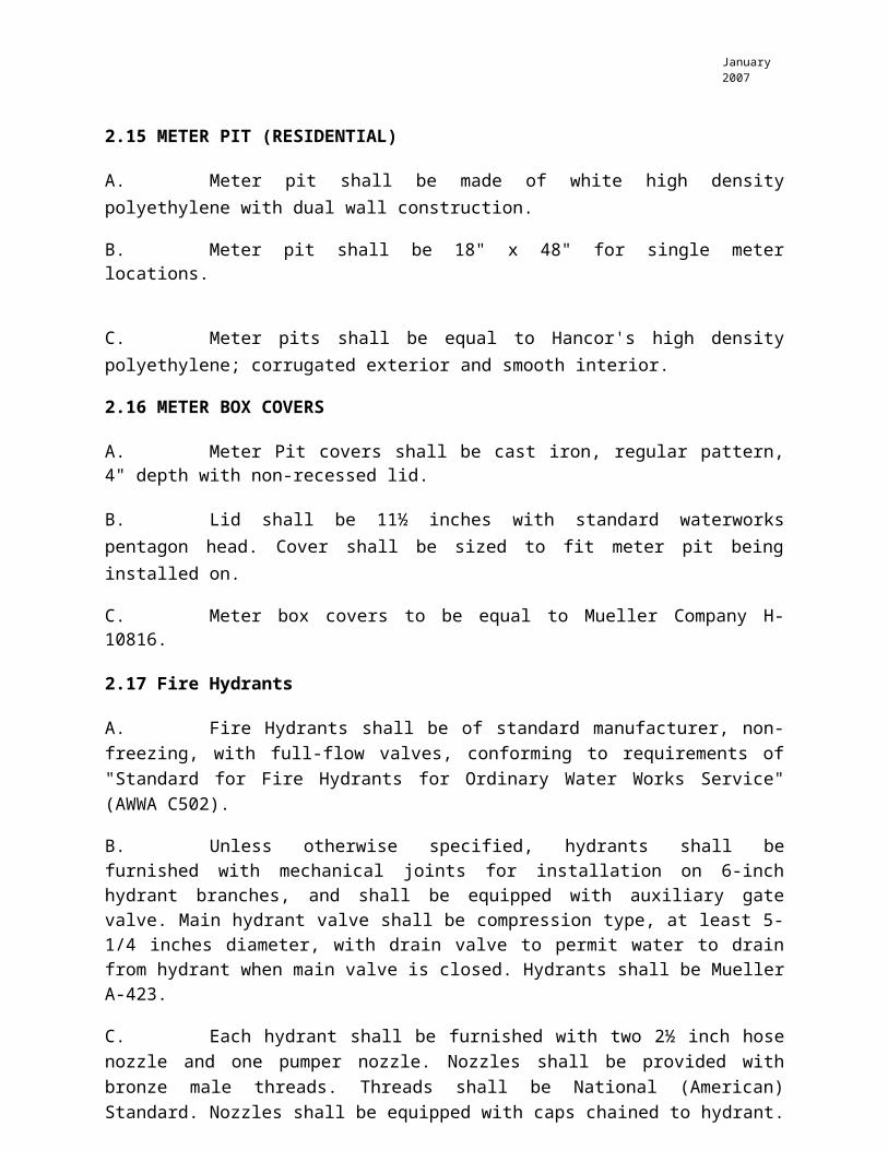
2.15 METER PIT (RESIDENTIAL)
A. Meter pit shall be made of white high density polyethylene with dual wall construction.
B. Meter pit shall be 18" x 48" for single meter locations.
C. Meter pits shall be equal to Hancor's high density polyethylene; corrugated exterior and smooth interior.
2.16 METER BOX COVERS
A. Meter Pit covers shall be cast iron, regular pattern, 4" depth with non-recessed lid.
B. Lid shall be 11½ inches with standard waterworks pentagon head. Cover shall be sized to fit meter pit being installed on.
C. Meter box covers to be equal to Mueller Company H-10816.
2.17 Fire Hydrants
A. Fire Hydrants shall be of standard manufacturer, non-freezing, with full-flow valves, conforming to requirements of "Standard for Fire Hydrants for Ordinary Water Works Service" (AWWA C502).
B. Unless otherwise specified, hydrants shall be furnished with mechanical joints for installation on 6-inch hydrant branches, and shall be equipped with auxiliary gate valve. Main hydrant valve shall be compression type, at least 5-1/4 inches diameter, with drain valve to permit water to drain from hydrant when main valve is closed. Hydrants shall be Mueller A-423.
C. Each hydrant shall be furnished with two 2½ inch hose nozzle and one pumper nozzle. Nozzles shall be provided with bronze male threads. Threads shall be National (American) Standard. Nozzles shall be equipped with caps chained to hydrant.
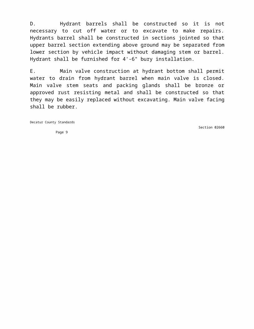
D. Hydrant barrels shall be constructed so it is not necessary to cut off water or to excavate to make repairs. Hydrants barrel shall be constructed in sections jointed so that upper barrel section extending above ground may be separated from lower section by vehicle impact without damaging stem or barrel. Hydrant shall be furnished for 4'-6" bury installation.
E. Main valve construction at hydrant bottom shall permit water to drain from hydrant barrel when main valve is closed. Main valve stem seats and packing glands shall be bronze or approved rust resisting metal and shall be constructed so that they may be easily replaced without excavating. Main valve facing shall be rubber.
Decatur County StandardsSection 02660
Page 9
January 2007
2.18 FLUSH HYDRANT
A. Flush hydrants shall be of standard manufacturer non-freezing, post type dry barrel design.
B. Design shall be low maintenance post type dry barrel with special union functions as traffic feature.
C. Hydrant shall be furnished with 2½ inch National Standard Hose thread. Shut-off valve shall have integral drain to allow hydrant post to drain after use to prevent freezing.
D. Hydrant shall be buried to a depth of 48 inches with normal height above ground of 21 inches.
E. All below ground components are to be made from waterworks brass. Above ground components are to be painted "RED".
F. Hydrant shall be equal to Mueller Company A-408.
3.0 Execution
3.1 Pipe Installation
A. Clean and remove all foreign material from the inside of the pipe, and from the ends of the pipe.
B. Water mains shall be laid and maintained to an invert grade 48 inches plus diameter (48"+ diameter) of pipe below finished ground line unless otherwise approved. Alignment shall follow location shown on plans. Whenever obstructions not known are encountered during progress of work and interfere to such extent that alteration in plan is required, the location, change pipe location from that shown.
C. Trench bottom shall be smooth and free from rocks or any other hard objects. Trench shall be excavated to depth 4" below invert grade and backfilled to invert grade with compacted coarse sand bedding material.
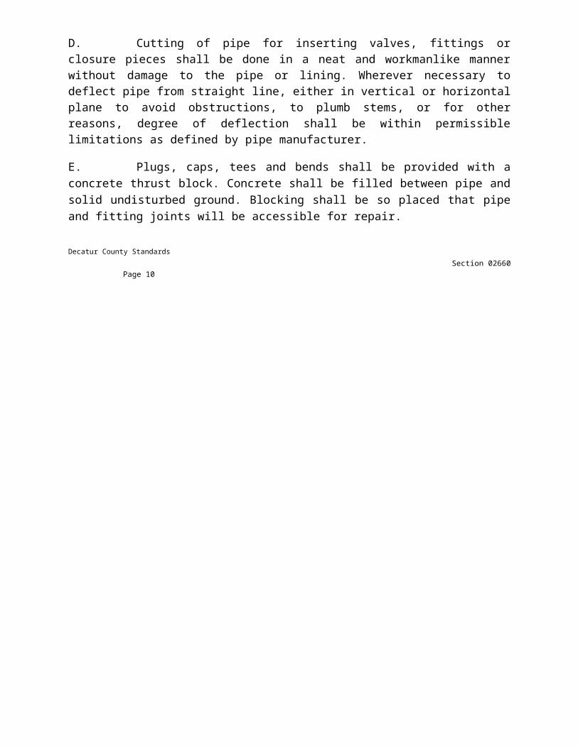
D. Cutting of pipe for inserting valves, fittings or closure pieces shall be done in a neat and workmanlike manner without damage to the pipe or lining. Wherever necessary to deflect pipe from straight line, either in vertical or horizontal plane to avoid obstructions, to plumb stems, or for other reasons, degree of deflection shall be within permissible limitations as defined by pipe manufacturer.
E. Plugs, caps, tees and bends shall be provided with a concrete thrust block. Concrete shall be filled between pipe and solid undisturbed ground. Blocking shall be so placed that pipe and fitting joints will be accessible for repair.
Decatur County StandardsSection 02660
Page 10

January 2007
F. Restraints shall be install at tees and bends, fire hydrants and locations requiring thrust blocks.
G. Tapping
1. Ductile Iron tapping for service lines greater than ¾" shall be made with tapping saddles.
2. Polyvinyl Chloride tapping for service lines 2" and less shall be made through service clamps or wide strap tapping saddles. For outlets larger than 2 inches, use tapping sleeve and valve.
3. Service lines shall be connected to new main at location of existing lines. Building services to new mains shall not be made until newly constructed mains have been disinfected and satisfactorily tested.
H. All non-metallic pipe shall have a 10 gauge copper tracer wire placed on top of pipe before backfilling. Wire shall be turned up at valves and hydrants. Blue plastic warning tape shall be placed in trench 18" above pipe.
I. Connection to existing main shall be made in as short a time as possible. Contractor shall schedule cut-ins and notify Owner and Utility Superintendent at least 72 hours before proceeding so arrangements can be made for inspection of work and affected water customers can be notified. All water customers who will be affected by isolated sections of mains for purpose of making cut-in connections and disinfection are to be given advance notice by Owner through the local newspaper or by personal notice to each customers.
3.2 RESIDENTIAL METERS
A. Single meters ⅝" through 1" shall be installed in 18" x 48" meter pit complete with pit cover, yoke and fittings.
3.3 METER PITSA. Non-Traffic Areas - Compact sand 6 inches outside pit and to top of HDPE. Place lid on pit and fill with 4 inches of top soil.
B. Traffic Areas - Fill void around pit with 4000 psi concrete minimum 4 inches thick. Place lid to bear on concrete to transfer all traffic loads to concrete and surrounding soil.
3.4 Excavation and Backfill
A. Except as otherwise specified, all excavation shall be as specified in Section 02222.
B. Included in this work shall be removal of existing sidewalks, curbs, fences and miscellaneous items as is necessary to construct the water line. All sidewalks, curbs and roadways shall be saw cut and removed to straight neat lines.
Decatur County StandardsSection 02660
Page 11

January 2007
C. Where permitted, trenches cut in roads, streets and drives shall be completed as specified in Section 02505. All work shall conform to the latest edition of INDOT Standard Specifications.
3.5 Restoration
A. Included as part of the work under this section the contractor shall fully replace and/or restore all streets, yards, parking lots, sidewalks, curbs, driveways, fences and miscellaneous items to a condition equal to or exceeding that which was disturbed.
3.6 Hydrostatic Testing
A. After water lines have been laid and backfilled, all newly laid pipe or any valved section of it shall be subjected to hydrostatic pressure of at least 120 psi, or twice the working pressure, which ever is greater. Duration of each pressure test shall be at least two hours in presence of Utility representative. Utility to be notified 24 hours prior to test.
B. Each valved section of pipe shall be slowly filled with water and specified test pressure shall be applied by means of a pump connected to pipe in satisfactory manner. Contractor shall furnish pump, pipe, connection and all necessary apparatus including gages and meter for test, and shall make all taps into pipe. Before applying specified test pressure, all air shall be expelled from pipe. To accomplish this, taps shall be made, if necessary, at points of highest elevation and afterwards tightly plugged.
C. Exposed pipes, fittings, valves, hydrants and joints will be carefully examined during open trench test. Any cracked or defective pipe, fittings, valves or hydrants discovered as a result of this pressure test shall be removed and replaced by Contractor, at his expense, with sound material. Test shall be repeated until all leaks are satisfactorily repaired.
D. Suitable means shall be provided by Contractor for determining quantity of water lost by leakage under normal operating pressure. No pipe installation will be accepted until or unless this leakage, evaluated on a pressure basis of 150 psig, is within a tolerance of 25 gallons per 24 hours per mile of pipe per inch nominal diameter of pipe.
E. Should any test of combined sections of pipe laid, disclose leakage greater than that allowed above, or if individual sections show leakage greater than 25% above specified tolerance, Contractor shall at his own expense locate and repair defects until leakage is within specified tolerance. Leakage is defined as quantity of water to be supplied into new laid pipe, or any valved section of it, necessary to maintain specified leakage test pressure after pipe has been filled with water and air expelled.
F. Pipe lines may be subjected to hydrostatic pressure, inspected, and tested for leakage at any convenient time after partial completion of backfill, and after concrete thrust blocking has had ample time to harden.
G. Air shall not be used to maintain required test pressure in pipe.
Decatur County StandardsSection 02660
Page 12

January 2007
3.7 Sterilization of Water Mains
A. Before being placed in service, all new water distribution systems, or extensions to existing system, or any valved section of such, shall be disinfected. Prior to sterilization, dirt remaining in pipe after its completion shall be removed by thorough flushing through hydrants, where available; otherwise through other approved temporary connections to be provided by contractor for this purpose. This shall be done after hydrostatic testing and may be done either before or after trench has been backfilled. Each valved section of newly laid pipe shall be flushed independently. Flushing velocity shall be not less than 2.5 feet per second through completed new main. All disinfection shall be done in accordance with AWWA Standard C601.
B. Chlorine gas-water mixture shall be applied by means of solution-feed chlorinating device or, if approved by Utility Engineer, gas shall be fed directly from chlorine cylinder equipped with proper devices for regulating rate of flow and effective diffusion of gas within pipe. Also, where approved by Utility Engineer, solution of calcium hypochlorite (H.T.H. or Perchloron or equal may be injected under low pressure.
C. Preferable point of application of chlorinating agent shall be at beginning of pipe line extension, or any valved section of it, through a corporation stop inserted in side of newly laid pipe. Water injector for delivering gas-water or calcium hypochlorite mixture into pipe shall be supplied from a tap on upstream side of gate valve controlling flow into new pipe line section.
D. Water from existing distribution system or any completed extension of it entering newly laid pipe line shall be controlled to flow very slowly during application of chlorine. Rate of chlorine gas water mixture or calcium hypochlorite solution flow shall be in such proportion to rate of water entering pipe that treated chlorine residual. Back pressure, causing reversal or flow in pipe being treated shall be prevented. Chlorine solution shall remain in pipe for at least 24 hours. After chlorine-treated water has been retained for required time, chlorine residual at pipe extremities and at other representative points shall be at least 25 mg/1. Contractor shall provide equipment to perform chlorine residual test.
E. In process of chlorinating newly laid water pipe involving more than one valved section, all valves or other appurtenances shall be operated while pipe line is filled with chlorinating agent.
F. Following chlorinating, all treated water shall be thoroughly flushed from newly laid pipe line at its extremities until replacement water throughout its length shall, upon test, be proved comparable in quality to water served public from existing water supply system. Samples of water for tests shall be taken under direction of Utility Engineer and in accordance with methods of sampling as recommended by appropriate State Health Agency. Bacteriological tests shall be performed by State Laboratory or by a testing laboratory which is approved for bacteriological testing by State. Contractor shall send samples to State Laboratory and pay all costs of sampling and testing.
Decatur County StandardsSection 02660
Page 13

January 2007
G. At least two sets of successive satisfactory bacteriological samples taken at 24 hour intervals shall be obtained from newly laid pipe lines and equipment before water is discharged through them to existing system. New piping shall be lightly flushed a second time prior to taking second sample. Should test of second or last taken sample prove ineffective, chlorination procedure shall be repeated until confirmed tests show that water sampled from newly laid pipe conforms to requirement stated above.
3.8 Chlorination Procedure When Cutting Into Existing Mains
A. Under ideal trench and installation conditions with full-time inspection by Utility Engineer, Contractor may be permitted to make cuts into existing pipe lines for insertion of valves, fittings, repairs or for other purposed by following procedure of disinfection: Sprinkle inside surfaces of appurtenances to be installed with a dry hypochlorite (or apply a hypochlorite slurry) and place small quantity of hypochlorite powder into ends of existing pipe on either side of opening before new pipe and fittings are installed.
END SECTION 02660
Decatur County StandardsSection 02660
Page 14
January 2007
Decatur County Standards

Section 02660
Page 15
January 2007
Decatur County Standards
Section 02660
Page 16

January 2007
Decatur County Standards
Section 02660
Page 17
January 2007
Decatur County Standards

Section 02660
Page 18

January 2007
Decatur County Standards
Section 02660
Page 19
January 2007
Decatur County Standards

Section 02660
Page 20


![Resident Evil® Revelation disc with the label facing up into the disc slot. Select the icon for the software title under [Game] in the PS3™ system’s home menu, and then press](https://static.fdocuments.net/doc/165x107/5e6a99a1f0347950916493f1/resident-evil-revelation-disc-with-the-label-facing-up-into-the-disc-slot-select.jpg)