€¦ · Web viewSEPERABLE REVERSINLE DATA HIDING IN AN ENCRYPTED IMAGE. ABSTRACT. This work...
72
SEPERABLE REVERSINLE DATA HIDING IN AN ENCRYPTED IMAGE ABSTRACT This work proposes a novel scheme for separable reversible data hiding in encrypted images. In the first phase, a content owner encrypts the original uncompressed image using an encryption key. Then, a data-hider may compress the least significant bits of the encrypted image using a data-hiding key to create a sparse space to accommodate some additional data. With an encrypted image containing additional data, if a receiver has the data-hiding key, he can extract the additional data though he does not know the image content. If the receiver has the encryption key, he can decrypt the received data to obtain an image similar to the original one, but cannot extract the additional data. If the receiver has both the data-hiding key and the encryption key, he can extract the additional data and recover the original content without any error by exploiting the spatial correlation in natural image 1
Transcript of €¦ · Web viewSEPERABLE REVERSINLE DATA HIDING IN AN ENCRYPTED IMAGE. ABSTRACT. This work...
SEPERABLE REVERSINLE DATA HIDING IN AN ENCRYPTED IMAGE
ABSTRACT
This work proposes a novel scheme for separable reversible data hiding in
encrypted images. In the first phase, a content owner encrypts the original
uncompressed image using an encryption key. Then, a data-hider may compress
the least significant bits of the encrypted image using a data-hiding key to create a
sparse space to accommodate some additional data. With an encrypted image
containing additional data, if a receiver has the data-hiding key, he can extract the
additional data though he does not know the image content. If the receiver has the
encryption key, he can decrypt the received data to obtain an image similar to the
original one, but cannot extract the additional data. If the receiver has both the
data-hiding key and the encryption key, he can extract the additional data and
recover the original content without any error by exploiting the spatial correlation
in natural image when the amount of additional data is not too large.
1
LIST OF FIGURES
FIGURE NO FIGURE NAME PAGENO
1. . NET FRAMEWORK 24
2. ARCHITECTURE DIAGRAM 32
3. SEPARABLE SCHEME. 36
2
LIST OF ABBREVATIONS
ABBREVATIONS EXPANSIONS
LSB LEAST SIGNIFICANT BIT
MSB MOST SIGNIFICANT BIT
BPP BIT PER PIXEL
PSNR PEAK SIGNAL TO NOISE RATIO
DCT DISCRETE COSINE TRANSFORMATION
3
TABLE OF CONTENT
CHAPTER NO TITLE PAGE NO
ABSTRACT 2
i LIST OF FIGURES 3 ii LIST OF ABBREVATIONS 4 iii
1. INTRODUCTION
1.1 GENERAL 9
2. FEASILIBILITY STUDY
2.1 ECONOMICAL FEASILIBILITY 13
2.2 TECHINICAL FEASILIBILITY 14
2.3 SOCIAL FEASILIBILITY 14
3. SYSTEM ANALYSIS
3.1 EXISTING SYSTEM 16
3.2 PROPOSED SYSTEM 16
4. REQUIREMENTS AND SPECIFICATIONS
4.1SOFTWARE REQUIREMENT
SPECIFICATION 18
4.2 SYSTEM REQUIREMENT 18
4.2.1 HARDWARE REQUIREMENT 184
4.2.2 SOFTWARE REQUIREMENT 18
5. SOFTWARE DESCRIPITION
5.1 FEATURES OF .NET 20
5.2 THE .NET FRAMEWORK 21
5.3 LANGUAGES SUPPORTED BY .NET 23
5.4 OBJECTIVES OF .NET FRAMEWORK 27
5.5 FEATURES OF SQL-SERVER 28
6. SYSTEM DESIGN
6.1 ARCHITECTURE DIAGRAM 32
7. IMPLEMENTATION
7.1 MODULES 34
7.1.1 IMAGE ENCRYPTION 34
7.1.2. DATA EXTRACTION 35
7.1.3. IMAGE RECOVERY 35
8. SYSTEM TESTING AND MAINTENANCE 37
9. FUTURE ENHANCEMENT
9.1 SUMMARY 47
9.2 FUTURE ENHANCEMENT 48
10. APPENDIX
10.1.1 CODINGS 50
10.1.2 SCREENSHOTS 52
5
CHAPTER 1
INTRODUCTION
6
INTRODUCTION
1.1 GENERAL
In recent years, signal processing in the encrypted domain has attracted
considerable research interest. As an effective and popular means for privacy
protection, encryption converts the ordinary signal into unintelligible data, so that
the traditional signal processing usually takes place before encryption or after
decryption. However, in some scenarios that a content owner does not trust the
processing service provider, the ability to manipulate the encrypted data when
keeping the plain content unrevealed is desired. For instance, when the secret data
to be transmitted are encrypted, a channel provider without any knowledge of the
cryptographic key may tend to compress the encrypted data due to the limited
channel resource. While an encrypted binary image can be compressed with a
lossless manner by finding the syndromes of low-density parity-check codes, a
lossless compression method for encrypted gray image using progressive
decomposition and rate-compatible punctured turbo codes is developed. With the
lossy compression method presented in an encrypted gray image can be efficiently
compressed by discarding the excessively rough and fine information of
coefficients generated from orthogonal transform. When having the compressed
data, a receiver may reconstruct the principal content of original image by
retrieving the values of coefficients. The computation of transform in the encrypted
domain has also been studied. Based on the homomorphic properties of the
underlying cryptosystem, the discrete Fourier transform in the encrypted domain
7

can be implemented. In a composite signal representation method packing together
a number of signal samples and processing them as a unique sample is used to
reduce the complexity of computation and the size of encrypted data. There are
also a number of works on data hiding in the encrypted domain. In a buyer–seller
watermarking protocol, the seller of digital multimedia product encrypts the
original data using a public key, and then permutes and embeds an encrypted
fingerprint provided by the buyer in the encrypted domain. After decryption with a
private key, the buyer can obtain a watermarked product. This protocol ensures that
the seller cannot know the buyer’s watermarked version while the buyer cannot
know the original version. An anonymous fingerprinting scheme that improves the
enciphering rate by exploiting the Okamoto-Uchiyama encryption method has been
proposed. By introducing the composite signal representation mechanism, both the
computational overhead and the large communication bandwidth due to the
homomorphic public-key encryption are also significantly reduced .In another type
of joint data-hiding and encryption schemes, a part of cover data is used to carry
the additional message and the rest of the data are encrypted, so that both the
copyright and the privacy can be protected. The intraprediction mode, motion
vector difference and signs of DCT coefficients are encrypted, while a watermark
is embedded into the amplitudes of DCT coefficients. In the cover data in higher
and lower bit-planes of transform domain are respectively encrypted and
watermarked. In the content owner encrypts the signs of host DCT coefficients and
each content-user uses a different key to decrypt only a subset of the coefficients,
so that a series of versions containing different fingerprints are generated for the
users.The reversible data hiding in encrypted image is investigated in Most of the
work on reversible data hiding focuses on the data embedding/extracting on the
plain spatial domain. But, in some applications, an inferior assistant or a channel
administrator hopes to append some additional message, such as the origin 8
information, image notation or authentication data, within the encrypted image
though he does not know the original image content. And it is also hopeful that the
original content should be recovered without any error after image decryption and
message extraction at receiver side. A content owner encrypts the original image
using an encryption key, and a data-hider can embed additional data into the
encrypted image using a data-hiding key though he does not know the original
content. With an encrypted image containing additional data, a receiver may first
decrypt it according to the encryption key, and then extract the embedded data and
recover the original image according to the data-hiding key. In the scheme, the data
extraction is not separable from the content decryption. In other words, the
additional data must be extracted from the decrypted image, so that the principal
content of original image is revealed before data extraction, and, if someone has
the data-hiding key but not the encryption key, he cannot extract any information
from the encrypted image containing additional data. This paper proposes a novel
scheme for separable reversible data hiding in encrypted image. In the proposed
scheme, the original image is encrypted using an encryption key and the additional
data are embedded into the encrypted image using a data-hiding key. With an
encrypted image containing additional data, if the receiver has only the data-hiding
key, he can extract the additional data though he does not know the image content.
If he has only the encryption key, he can decrypt the received data to obtain an
image similar to the original one, but cannot extract the embedded additional data.
If the receiver has both the data-hiding key and the encryption key, he can extract
the additional data and recover the original image without any error when the
amount of additional data is not too large.
9
CHAPTER 2
SYSTEM STUDY
10
SYSTEM STUDY
2.FEASIBILITY STUDY
The feasibility of the project is analyzed in this phase and business proposal
is put forth with a very general plan for the project and some cost estimates.
During system analysis the feasibility study of the proposed system is to be carried
out. This is to ensure that the proposed system is not a burden to the company. For
feasibility analysis, some understanding of the major requirements for the system
is essential.
Three key considerations involved in the feasibility analysis are
ECONOMICAL FEASIBILITY
TECHNICAL FEASIBILITY
SOCIAL FEASIBILITY
2.1 ECONOMICAL FEASIBILITY
This study is carried out to check the economic impact that the system will
have on the organization. The amount of fund that the company can pour into the
research and development of the system is limited. The expenditures must be
justified. Thus the developed system as well within the budget and this was
achieved because most of the technologies used are freely available. Only the
customized products had to be purchased. 11
2.2 TECHNICAL FEASIBILITY
This study is carried out to check the technical feasibility, that is, the
technical requirements of the system. Any system developed must not have a high
demand on the available technical resources. This will lead to high demands on the
available technical resources. This will lead to high demands being placed on the
client. The developed system must have a modest requirement, as only minimal or
null changes are required for implementing this system.
2.3 SOCIAL FEASIBILITY
The aspect of study is to check the level of acceptance of the system by the
user. This includes the process of training the user to use the system efficiently.
The user must not feel threatened by the system, instead must accept it as a
necessity. The level of acceptance by the users solely depends on the methods that
are employed to educate the user about the system and to make him familiar with
it. His level of confidence must be raised so that he is also able to make some
constructive criticism, which is welcomed, as he is the final user of the system.
12
CHAPTER 3
SYSTEM ANALYSIS
13
3. SYSTEM ANALYSIS
System Analysis is a combined process dissecting the system responsibilities that
are based on the problem domain characteristics and user requirements.
3.1 EXISTING SYSTEM
In some applications, an inferior assistant or a channel administrator hopes
to append some additional message, such as the origin information, image notation
or authentication data, within the encrypted image though he does not know the
original image content. some parameters are embedded into a small number of
encrypted pixels, and the of the other encrypted pixels are compressed to create a
space for accommodating the additional data and the original data at the positions
occupied by the parameters
3.2 PROPOSED SYSTEM
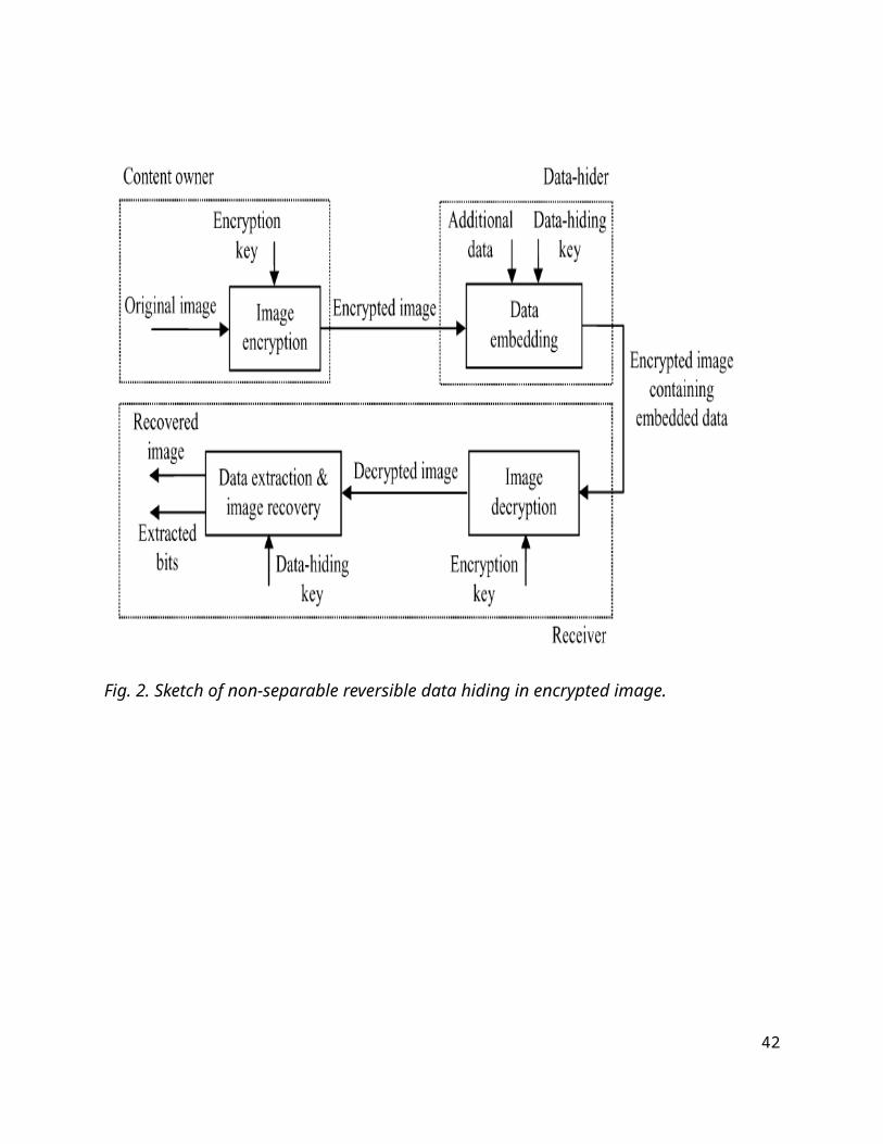
The proposed scheme is made up of image encryption, data embedding and
data-extraction/image-recovery phases. The content owner encrypts the original
uncompressed image using an encryption key to produce an encrypted image.
Then, the data-hider compresses the least significant bits (LSB) of the encrypted
image using a data-hiding key to create a sparse space to accommodate the
additional data. At the receiver side, the data embedded in the created space can be
easily retrieved from the encrypted image containing additional data according to
the data-hiding key. Since the data embedding only affects the LSB, a decryption
with the encryption key can result in an image similar to the original version.
When using both of the encryption and data-hiding keys, the embedded additional
data can be successfully extracted and the original image can be perfectly
recovered by exploiting the spatial correlation in natural image
14
CHAPTER 4
SYSTEM REQUIREMENTS
15
4. REQUIREMENTS AND SPECIFICATION
4.1 SOFTWARE REQUIREMENTS SPECIFICATION
The software requirements specification is produced at the culmination
of the analysis task. The function and performance allocated to software as part of
system engineering are refined by establishing a complete information description
as functional representation of system behavior, an indication of performance
requirements and design constraints, appropriate validation criteria.
4.2 SYSTEM REQUIREMENTS
4.2.1HARDWARE REQUIREMENTS
• System : Pentium IV and above.
• Hard Disk : 40 GB or Above.
• Monitor : VGA and High resolution monitor
• Mouse : Logitech.
• Ram : 1 GB or Above
4.2.2 SOFTWARE REQUIREMENTS
• Operating system : Windows XP.
• Coding Language : ASP.Net with C#
• Data Base : SQL Server 2005
16
CHAPTER 5
SOFTWARE DESCRIPTION
17

5. SOFTWARE DESCRIPTION
5.1. FEATURES OF .NET
Microsoft .NET is a set of Microsoft software technologies for rapidly
building and integrating XML Web services, Microsoft Windows-based
applications, and Web solutions. The .NET Framework is a language-neutral
platform for writing programs that can easily and securely interoperate. There’s no
language barrier with .NET: there are numerous languages available to the
developer including Managed C++, C#, Visual Basic and Java Script. The .NET
framework provides the foundation for components to interact seamlessly, whether
locally or remotely on different platforms. It standardizes common data types and
communications protocols so that components created in different languages can
easily interoperate.
“.NET” is also the collective name given to various software components
built upon the .NET platform. These will be both products (Visual Studio.NET and
Windows.NET Server, for instance) and services (like Passport, .NET My Services,
and so on).
5.2. THE .NET FRAMEWORK
The .NET Framework has two main parts:
1. The Common Language Runtime (CLR).
2. A hierarchical set of class libraries.
The CLR is described as the “execution engine” of .NET. It provides the
environment within which programs run. The most important features are
18
Conversion from a low-level assembler-style language, called
Intermediate Language (IL), into code native to the platform being
executed on.
Memory management, notably including garbage collection.
Checking and enforcing security restrictions on the running code.
Loading and executing programs, with version control and other such
features.
The following features of the .NET framework are also worth
description:
MANAGED CODE
The code that targets .NET, and which contains certain extra Information -
“metadata” - to describe itself. Whilst both managed and unmanaged code can run
in the runtime, only managed code contains the information that allows the CLR to
guarantee, for instance, safe execution and interoperability.
MANAGED DATA
With Managed Code comes Managed Data. CLR provides memory
allocation and Deal location facilities, and garbage collection. Some .NET
languages use Managed Data by default, such as C#, Visual Basic.NET and
JScript.NET, whereas others, namely C++, do not. Targeting CLR can, depending
on the language you’re using, impose certain constraints on the features available.
As with managed and unmanaged code, one can have both managed and
unmanaged data in .NET applications - data that doesn’t get garbage collected but
instead is looked after by unmanaged code.19
COMMON TYPE SYSTEM
The CLR uses something called the Common Type System (CTS) to strictly
enforce type-safety. This ensures that all classes are compatible with each other, by
describing types in a common way. CTS define how types work within the
runtime, which enables types in one language to interoperate with types in another
language, including cross-language exception handling. As well as ensuring that
types are only used in appropriate ways, the runtime also ensures that code doesn’t
attempt to access memory that hasn’t been allocated to it.
COMMON LANGUAGE SPECIFICATION
The CLR provides built-in support for language interoperability. To ensure
that you can develop managed code that can be fully used by developers using any
programming language, a set of language features and rules for using them called
the Common Language Specification (CLS) has been defined. Components that
follow these rules and expose only CLS features are considered CLS-compliant.
THE CLASS LIBRARY
.NET provides a single-rooted hierarchy of classes, containing over 7000
types. The root of the namespace is called System; this contains basic types like
Byte, Double, Boolean, and String, as well as Object. All objects derive from
System. Object. As well as objects, there are value types. Value types can be
allocated on the stack, which can provide useful flexibility. There are also efficient
means of converting value types to object types if and when necessary.
The set of classes is pretty comprehensive, providing collections, file,
20
screen, and network I/O, threading, and so on, as well as XML and database
connectivity.
The class library is subdivided into a number of sets (or namespaces), each
providing distinct areas of functionality, with dependencies between the
namespaces kept to a minimum.
5.3. LANGUAGES SUPPORTED BY .NET
The multi-language capability of the .NET Framework and Visual Studio .NET
enables developers to use their existing programming skills to build all types of
applications and XML Web services. The .NET framework supports new versions
of Microsoft’s old favourites Visual Basic and C++ (as VB.NET and Managed C+
+), but there are also a number of new additions to the family.
Visual Basic .NET has been updated to include many new and improved
language features that make it a powerful object-oriented programming language.
These features include inheritance, interfaces, and overloading, among others.
Visual Basic also now supports structured exception handling, custom attributes
and also supports multi-threading.
Visual Basic .NET is also CLS compliant, which means that any CLS-
compliant language can use the classes, objects, and components you create in
Visual Basic .NET.
Managed Extensions for C++ and attributed programming are just some of
the enhancements made to the C++ language. Managed Extensions simplify the
task of migrating existing C++ applications to the new .NET Framework.
C# is Microsoft’s new language. It’s a C-style language that is essentially
21
“C++ for Rapid Application Development”. Unlike other languages, its
specification is just the grammar of the language. It has no standard library of its
own, and instead has been designed with the intention of using the .NET libraries
as its own.
Microsoft Visual J# .NET provides the easiest transition for Java-language
developers into the world of XML Web Services and dramatically improves the
interoperability of Java-language programs with existing software written in a
variety of other programming languages.
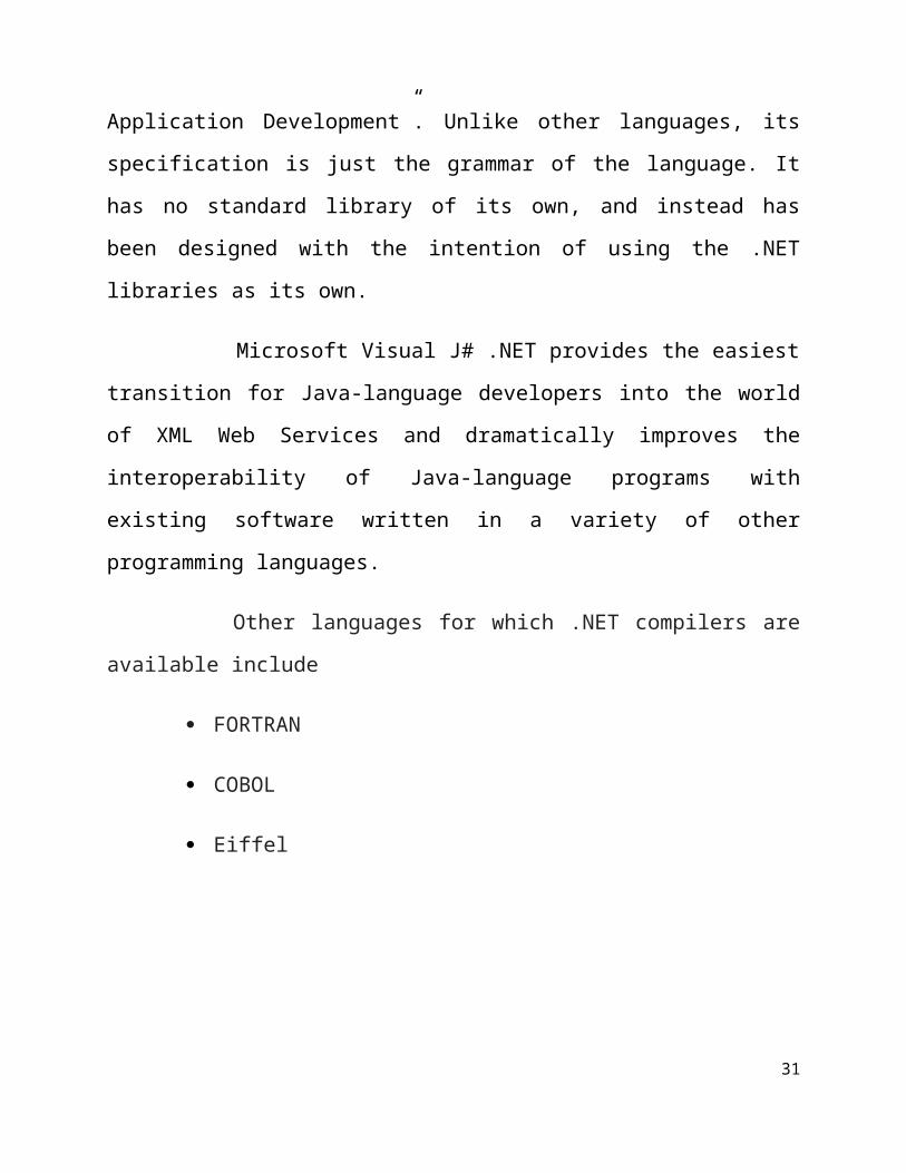
Other languages for which .NET compilers are available include
FORTRAN
COBOL
Eiffel
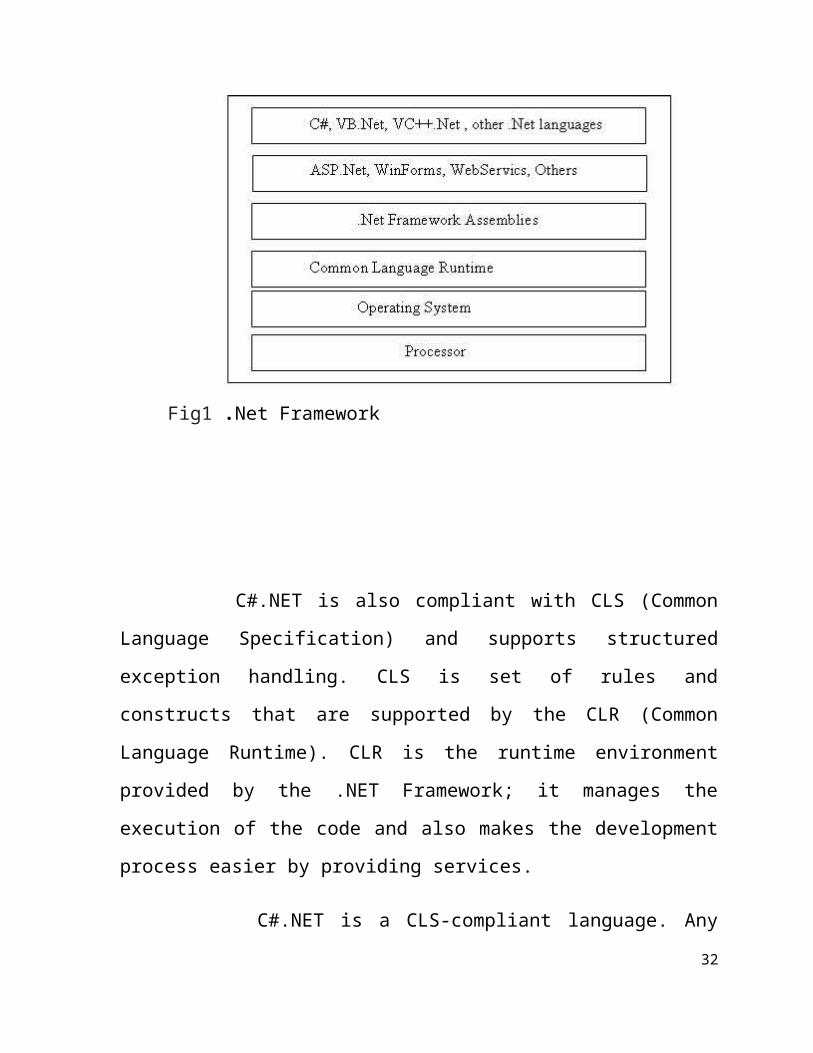
Fig1 .Net Framework
22
C#.NET is also compliant with CLS (Common Language Specification)
and supports structured exception handling. CLS is set of rules and constructs
that are supported by the CLR (Common Language Runtime). CLR is the
runtime environment provided by the .NET Framework; it manages the
execution of the code and also makes the development process easier by
providing services.
C#.NET is a CLS-compliant language. Any objects, classes, or
components that created in C#.NET can be used in any other CLS-compliant
language. In addition, we can use objects, classes, and components created in
other CLS-compliant languages in C#.NET .The use of CLS ensures complete
interoperability among applications, regardless of the languages used to create
the application.
CONSTRUCTORS AND DESTRUCTORS
Constructors are used to initialize objects, whereas destructors are used to
destroy them. In other words, destructors are used to release the resources
allocated to the object. In C#.NET the sub finalize procedure is available. The
sub finalize procedure is used to complete the tasks that must be performed
when an object is destroyed. The sub finalize procedure is called automatically
when an object is destroyed. In addition, the sub finalize procedure can be
called only from the class it belongs to or from derived classes.
23
GARBAGE COLLECTION
Garbage Collection is another new feature in C#.NET. The .NET Framework
monitors allocated resources, such as objects and variables. In addition,
the .NET Framework automatically releases memory for reuse by destroying
objects that are no longer in use.
In C#.NET, the garbage collector checks for the objects that are not currently in
use by applications. When the garbage collector comes across an object that is
marked for garbage collection, it releases the memory occupied by the object.
OVERLOADING
Overloading is another feature in C#. Overloading enables us to define
multiple procedures with the same name, where each procedure has a different
set of arguments. Besides using overloading for procedures, we can use it for
constructors and properties in a class.
MULTITHREADING
C#.NET also supports multithreading. An application that supports
multithreading can handle multiple tasks simultaneously, we can use
multithreading to decrease the time taken by an application to respond to user
interaction.
STRUCTURED EXCEPTION HANDLING
C#.NET supports structured handling, which enables us to detect and
remove errors at runtime. In C#.NET, we need to use Try…Catch…Finally
24
statements to create exception handlers. Using Try…Catch…Finally statements,
we can create robust and effective exception handlers to improve the
performance of our application.
THE .NET FRAMEWORK
The .NET Framework is a new computing platform that simplifies
application development in the highly distributed environment of the Internet.
5.4. OBJECTIVES OF. NET FRAMEWORK
1. To provide a consistent object-oriented programming environment whether
object codes is stored and executed locally on Internet-distributed, or executed
remotely.
2. To provide a code-execution environment to minimizes software deployment
and guarantees safe execution of code.
3. Eliminates the performance problems.
4. There are different types of application, such as Windows-based applications
and Web-based applications.
5.5. FEATURES OF SQL-SERVER
The OLAP Services feature available in SQL Server version 7.0 is now
called SQL Server 2000 Analysis Services. The term OLAP Services has been
replaced with the term Analysis Services. Analysis Services also includes a new
data mining component. The Repository component available in SQL Server
version 7.0 is now called Microsoft SQL Server 2000 Meta Data Services. 25
References to the component now use the term Meta Data Services. The term
repository is used only in reference to the repository engine within Meta Data
Services SQL-SERVER database consist of six type of objects, they are,
1. TABLE
2. QUERY
3. FORM
4. REPORT
5. MACRO
TABLE
A database is a collection of data about a specific topic.
VIEWS OF TABLE
We can work with a table in two types,
1. Design View
2. Datasheet View
DESIGN VIEW
To build or modify the structure of a table we work in the table design
view. We can specify what kind of data will be hold.
DATASHEET VIEW
To add, edit or analyses the data itself we work in tables datasheet view
26
mode.
QUERY
A query is a question that has to be asked the data. Access gathers data that
answers the question from one or more table. The data that make up the answer is
either dynaset (if you edit it) or a snapshot (it cannot be edited).Each time we run
query, we get latest information in the dynaset. Access either displays the dynaset
or snapshot for us to view or perform an action on it, such as deleting or updating.
CHAPTER 6
SYSTEM DESIGN
27
6. SYSTEM DESIGN
System Design involves identification of classes their relationship as well as
their collaboration. In objector, classes are divided into entity classes and control
classes. The Computer Aided Software Engineering (CASE) tools that are
available commercially do not provide any assistance in this transition. CASE tools
take advantage of Meta modelling that is helpful only after the construction of the
28
class diagram. In the FUSION method some object-oriented approach likes Object
Modelling Technique (OMT), Classes, and Responsibilities. Collaborators (CRC),
etc, are used. Objector used the term “agents” to represent some of the hardware
and software system. In Fusion method, there is no requirement phase, where a
user will supply the initial requirement document. Any software project is worked
out by both the analyst and the designer. The analyst creates the user case diagram.
The designer creates the class diagram. But the designer can do this only after the
analyst creates the use case diagram. Once the design is over, it is essential to
decide which software is suitable for the application
6.1 ARCHITECTURE DIAGRAM
29
Fig. 2. Sketch of non-separable reversible data hiding in encrypted image.
30
CHAPTER 7
IMPLEMENTATION
7. IMPLEMENTATION
Implementation is the stage of the project when the theoretical design is
turned out into a working system.
7.1 MODULES
31
1 .Image Encryption
2. Data Extraction
3. Image Recovery
MODULES DESCRIPTION
7.1.1 IMAGE ENCRYPTION
The reversible data hiding in encrypted image is investigated in. Most of the
work on reversible data hiding focuses on the data embedding/extracting on the
plain spatial domain. But, in some applications, an inferior assistant or a channel
administrator hopes to append some additional message, such as the origin
information, image notation or authentication data, within the encrypted image
though he does not know the original image content. And it is also hopeful that the
original content should be recovered without any error after image decryption and
message extraction at receiver side. A content owner encrypts the original image
using an encryption key, and a data-hider can embed additional data into the
encrypted image using a data-hiding key though he does not know the original
content.
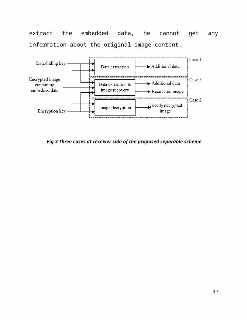
7.1.2 DATA EXTRACTION
Consider the three cases that a receiver has only the data-hiding key,
only the encryption key, and both the data-hiding and encryption keys,
respectively. With an encrypted image containing embedded data, if the receiver
has only the data-hiding key, he may first obtain the values of the parameters from
the LSB of the selected encrypted pixels. Then, the receiver permutes and divides
the other pixels into groups and extracts the embedded bits from the LSB planes of
each group. When having the total extracted bits, the receiver can divide them into 32
original LSB of selected encrypted pixels and additional bits. Note that because of
the pseudo-random pixel selection and permutation, any attacker without the data-
hiding key cannot obtain the parameter values and the pixel-groups, therefore
cannot extract the embedded data. Furthermore, although the receiver having the
data-hiding key can successfully extract the embedded data, he cannot get any
information about the original image content.
7.1.3 IMAGE RECOVERY
In this phase, we will consider the three cases that a receiver has only the
data-hiding key, only the encryption key, and both the data-hiding and encryption
keys, respectively. Note that because of the pseudo-random pixel selection and
permutation, any attacker without the data-hiding key cannot obtain the parameter
values and the pixel-groups, therefore cannot extract the embedded data.
Furthermore, although the receiver having the data-hiding key can successfully
extract the embedded data, he cannot get any information about the original image
content.
Fig.3 Three cases at receiver side of the proposed separable scheme
33
34
CHAPTER 8
SYSTEM TESTING AND MAINTENANCE
TESTING
Software Testing is the process used to help identify the correctness,
completeness, security, and quality of developed computer software. Testing is a
process of technical investigation, performed on behalf of stakeholders, that is
intended to reveal quality-related information about the product with respect to the
context in which it is intended to operate. This includes, but is not limited to, the
process of executing a program or application with the intent of finding errors.
Quality is not an absolute; it is value to some person. With that in mind, testing can
never completely establish the correctness of arbitrary computer software; testing
furnishes a criticism or comparison that compares the state and behavior of the
product against a specification. An important point is that software testing should
35
be distinguished from the separate discipline of Software Quality Assurance
(SQA), which encompasses all business process areas, not just testing.
There are many approaches to software testing, but effective testing of
complex products is essentially a process of investigation, not merely a matter of
creating and following routine procedure. One definition of testing is "the process
of questioning a product in order to evaluate it", where the "questions" are
operations the tester attempts to execute with the product, and the product answers
with its behavior in reaction to the probing of the tester[citation needed]. Although
most of the intellectual processes of testing are nearly identical to that of review or
inspection, the word testing is connoted to mean the dynamic analysis of the
product—putting the product through its paces. Some of the common quality
attributes include capability, reliability, efficiency, portability, maintainability,
compatibility and usability. A good test is sometimes described as one which
reveals an error; however, more recent thinking suggests that a good test is one
which reveals information of interest to someone who matters within the project
community.
INTRODUCTION
In general, software engineers distinguish software faults from software
failures. In case of a failure, the software does not do what the user expects. A fault
is a programming error that may or may not actually manifest as a failure. A fault
can also be described as an error in the correctness of the semantic of a computer
program. A fault will become a failure if the exact computation conditions are met,
one of them being that the faulty portion of computer software executes on the
CPU. A fault can also turn into a failure when the software is ported to a different
hardware platform or a different compiler, or when the software gets extended.
36
Software testing is the technical investigation of the product under test to provide
stakeholders with quality related information.
Software testing may be viewed as a sub-field of Software Quality
Assurance but typically exists independently (and there may be no SQA areas in
some companies). In SQA, software process specialists and auditors take a broader
view on software and its development. They examine and change the software
engineering process itself to reduce the amount of faults that end up in the code or
deliver faster.
Regardless of the methods used or level of formality involved the desired
result of testing is a level of confidence in the software so that the organization is
confident that the software has an acceptable defect rate. What constitutes an
acceptable defect rate depends on the nature of the software. An arcade video game
designed to simulate flying an airplane would presumably have a much higher
tolerance for defects than software used to control an actual airliner.
A problem with software testing is that the number of defects in a software 1product can be very large, and the number of configurations of the product larger
still. Bugs that occur infrequently are difficult to find in testing. A rule of thumb is
that a system that is expected to function without faults for a certain length of time
must have already been tested for at least that length of time. This has severe
consequences for projects to write long-lived reliable software.
A common practice of software testing is that it is performed by an
independent group of testers after the functionality is developed but before it is
shipped to the customer. This practice often results in the testing phase being used
as project buffer to compensate for project delays. Another practice is to start
1 37
software testing at the same moment the project starts and it is a continuous
process until the project finishes.
Another common practice is for test suites to be developed during technical
support escalation procedures. Such tests are then maintained in regression testing
suites to ensure that future updates to the software don't repeat any of the known
mistakes.
It is commonly believed that the earlier a defect is found the cheaper it is to fix it.
In counterpoint, some emerging software disciplines such as extreme
programming and the agile software development movement, adhere to a "test-
driven software development" model. In this process unit tests are written first, by
the programmers (often with pair programming in the extreme programming
methodology). Of course these tests fail initially; as they are expected to. Then as
code is written it passes incrementally larger portions of the test suites. The test
suites are continuously updated as new failure conditions and corner cases are
discovered, and they are integrated with any regression tests that are developed.
Unit tests are maintained along with the rest of the software source code and
generally integrated into the build process (with inherently interactive tests being
relegated to a partially manual build acceptance process).
The software, tools, samples of data input and output, and configurations are
all referred to collectively as a test harness.
WHITE-BOX AND BLACK-BOX TESTING
To meet Wikipedia's quality standards, this section may require cleanup.
Please discuss this issue on the talk page, and/or replace this tag with a more
specific message.
38
White box and black box testing are terms used to describe the point of view a test
engineer takes when designing test cases. Black box being an external view of the
test object and white box being an internal view. Software testing is partly
intuitive, but largely systematic. Good testing involves much more than just
running the program a few times to see whether it works. Thorough analysis of the
program under test, backed by a broad knowledge of testing techniques and tools
are prerequisites to systematic testing. Software Testing is the process of executing
software in a controlled manner; in order to answer the question “Does this
software behave as specified?” Software testing is used in association with
Verification and Validation. Verification is the checking of or testing of items,
including software, for conformance and consistency with an associated
specification. Software testing is just one kind of verification, which also uses
techniques as reviews, inspections, walk-through. Validation is the process of
checking what has been specified is what the user actually wanted.
Validation: Are we doing the right job?
Verification: Are we doing the job right?
In order to achieve consistency in the Testing style, it is imperative to have and
follow a set of testing principles. This enhances the efficiency of testing within
SQA team members and thus contributes to increased productivity. The purpose of
this document is to provide overview of the testing, plus the techniques.
At SDEI, 3 levels of software testing is done at various SDLC phases
Unit Testing: in which each unit (basic component) of the software is tested
to verify that the detailed design for the unit has been correctly implemented
Integration testing: in which progressively larger groups of tested software
components corresponding to elements of the architectural design are
integrated and tested until the software works as a whole.
39
System testing: in which the software is integrated to the overall product and
tested to show that all requirements are met
A further level of testing is also done, in accordance with requirements:
Acceptance testing: upon which the acceptance of the complete software is
based. The clients often do this.
Regression testing: is used to refer the repetition of the earlier successful
tests to ensure that changes made in the software have not introduced new
bugs/side effects.
In recent years the term grey box testing has come into common usage. The typical
grey box tester is permitted to set up or manipulate the testing environment, like
seeding a database, and can view the state of the product after his actions, like
performing a SQL query on the database to be certain of the values of columns. It
is used almost exclusively of client-server testers or others who use a database as a
repository of information, but can also apply to a tester who has to manipulate
XML files (DTD or an actual XML file) or configuration files directly. It can also
be used of testers who know the internal workings or algorithm of the software
under test and can write tests specifically for the anticipated results. For example,
testing a data warehouse implementation involves loading the target database with
information, and verifying the correctness of data population and loading of data
into the correct tables.
TEST LEVELS
Unit testing tests the minimal software component and sub-component or
modules by the programmers.
Integration testing exposes defects in the interfaces and interaction between
integrated components (modules).
Functional testing tests the product according to programmable work. 40
System testing tests an integrated system to verify/validate that it meets its
requirements.
Acceptance testing testing can be conducted by the client. It allows the end-
user or customer or client to decide whether or not to accept the product.
Acceptance testing may be performed after the testing and before the
implementation phase. See also Development stage
o Alpha testing is simulated or actual operational testing by potential
users/customers or an independent test team at the developers' site.
Alpha testing is often employed for off-the-shelf software as a form of
internal acceptance testing, before the software goes to beta testing.
o Beta testing comes after alpha testing. Versions of the software,
known as beta versions, are released to a limited audience outside of
the company. The software is released to groups of people so that
further testing can ensure the product has few faults or bugs.
Sometimes, beta versions are made available to the open public to
increase the feedback field to a maximal number of future users.
It should be noted that although both Alpha and Beta are referred to as
testing it is in fact use emersion. The rigors that are applied are often unsystematic
and many of the basic tenets of testing process are not used. The Alpha and Beta
period provides insight into environmental and utilization conditions that can
impact the software.
After modifying software, either for a change in functionality or to fix
defects, a regression test re-runs previously passing tests on the modified software
to ensure that the modifications haven't unintentionally caused a regression of
previous functionality. Regression testing can be performed at any or all of the
above test levels. These regression tests are often automated.
41
TEST CASES, SUITES, SCRIPTS AND SCENARIOS
A test case is a software testing document, which consists of event, action,
input, output, expected result and actual result. Clinically defined (IEEE 829-1998)
a test case is an input and an expected result. This can be as pragmatic as 'for
condition x your derived result is y', whereas other test cases described in more
detail the input scenario and what results might be expected. It can occasionally be
a series of steps (but often steps are contained in a separate test procedure that can
be exercised against multiple test cases, as a matter of economy) but with one
expected result or expected outcome. The optional fields are a test case ID, test
step or order of execution number, related requirement(s), depth, test category,
author, and check boxes for whether the test is automatable and has been
automated. Larger test cases may also contain prerequisite states or steps, and
descriptions. A test case should also contain a place for the actual result. These
steps can be stored in a word processor document, spreadsheet, database or other
common repository. In a database system, you may also be able to see past test
results and who generated the results and the system configuration used to generate
those results. These past results would usually be stored in a separate table.
The term test script is the combination of a test case, test procedure and test
data. Initially the term was derived from the byproduct of work created by
automated regression test tools. Today, test scripts can be manual, automated or a
combination of both.
The most common term for a collection of test cases is a test suite. The test
suite often also contains more detailed instructions or goals for each collection of
test cases. It definitely contains a section where the tester identifies the system
configuration used during testing. A group of test cases may also contain
prerequisite states or steps, and descriptions of the following tests.
42

Collections of test cases are sometimes incorrectly termed a test plan. They
might correctly be called a test specification. If sequence is specified, it can be
called a test script, scenario or procedure.
A SAMPLE TESTING CYCLE
Although testing varies between organizations, there is a cycle to testing:
1. Requirements Analysis: Testing should begin in the requirements phase of
the software development life cycle.
During the design phase, testers work with developers in determining what
aspects of a design are testable and under what parameter those tests work.
2. Test Planning: Test Strategy, Test Plan(s), Test Bed creation.
3. Test Development: Test Procedures, Test Scenarios, Test Cases, Test Scripts
to use in testing software.
4. Test Execution: Testers execute the software based on the plans and tests and
report any errors found to the development team.
5. Test Reporting: Once testing is completed, testers generate metrics and make
final reports on their test effort and whether or not the software tested is
ready for release.
6. Retesting the Defects
Not all errors or defects reported must be fixed by a software development team.
Some may be caused by errors in configuring the test software to match the
development or production environment. Some defects can be handled by a
workaround in the production environment. Others might be deferred to future
releases of the software, or the deficiency might be accepted by the business user.
There are yet other defects that may be rejected by the development team (of
course, with due reason) if they deem it inappropriate to be called a defect.
43
CHAPTER 9
CONCLUSION AND FUTURE
ENCHANCEMENT
44
9.1 SUMMARY
45
In this project, a novel scheme for separable reversible data hiding in
encrypted image is proposed, which consists of image encryption, data embedding
and data-extraction/image-recovery phases. In the first phase, the content owner
encrypts the original uncompressed image using an encryption key. Although a
data-hider does not know the original content, he can compress the least significant
bits of the encrypted image using a data-hiding key to create a sparse space to
accommodate the additional data. With an encrypted image containing additional
data, the receiver may extract the additional data using only the data-hiding key, or
obtain an image similar to the original one using only the encryption key. When the
receiver has both of the keys, he can extract the additional data and recover the
original content without any error by exploiting the spatial correlation in natural
image if the amount of additional data is not too large. If the lossless compression
method in is used for the encrypted image containing embedded data, the
additional data can be still extracted and the original content can be also recovered
since the lossless compression does not change the content of the
encrypted image containing embedded data.
9.2 FUTURE ENHANCEMENTS
However, the lossy compression method in compatible with encrypted
images generated by pixel permutation is not suitable here since the encryption is
performed by bit-XOR operation. In the future, a comprehensive combination of
image encryption and data hiding compatible with lossy compression deserves
further investigation.
46
CHAPTER 10
APPENDIX47
10.2 SCREENSHOTS:
INPUT IMAGE:
48
KEY GENERATED:
49
ENCRYPT OUTPUT:
DECRYPT OUTPUT:
50
51