) Version 1 - OASISdocs.oasis-open.org/virtio/virtio/v1.0/csprd01/virtio-v1...1 Introduction...
69
Virtual I/O Device (VIRTIO) Version 1.0 Committee Specification Draft 01 / Public Review Draft 01 03 December 2013 Specification URIs This version: http://docs.oasis-open.org/virtio/virtio/v1.0/csprd01/virtio-v1.0-csprd01.pdf (Authoritative) http://docs.oasis-open.org/virtio/virtio/v1.0/csprd01/virtio-v1.0-csprd01.html Previous version: N/A Latest version: http://docs.oasis-open.org/virtio/virtio/v1.0/virtio-v1.0.pdf (Authoritative) http://docs.oasis-open.org/virtio/virtio/v1.0/virtio-v1.0.html Technical Committee: OASIS Virtual I/O Device (VIRTIO) TC Chair: Rusty Russell ([email protected]), IBM Editors: Michael S. Tsirkin ([email protected]), Red Hat Cornelia Huck ([email protected]), IBM Pawel Moll ([email protected]), ARM Limited Additional artifacts: This prose specification is one component of a Work Product that also includes: • Example Driver Listing: http://docs.oasis-open.org/virtio/virtio/v1.0/csprd01/listings/ • TeX source files for this prose document: http://docs.oasis-open.org/virtio/virtio/v1.0/csprd01/tex/ Related work: This specification replaces or supersedes: • Virtio PCI Card Specification Version 0.9.5: http://ozlabs.org/~rusty/virtio-spec/virtio-0.9.5.pdf virtio-v1.0-csprd01 Standards Track Work Product Copyright © OASIS Open 2013. All Rights Reserved. 03 December 2013 Page 1 of 69
Transcript of ) Version 1 - OASISdocs.oasis-open.org/virtio/virtio/v1.0/csprd01/virtio-v1...1 Introduction...

Virtual I/O Device (VIRTIO) Version 1.0Committee Specification Draft 01 /Public Review Draft 0103 December 2013Specification URIs
This version:http://docs.oasis-open.org/virtio/virtio/v1.0/csprd01/virtio-v1.0-csprd01.pdf (Authoritative)http://docs.oasis-open.org/virtio/virtio/v1.0/csprd01/virtio-v1.0-csprd01.html
Previous version:N/A
Latest version:http://docs.oasis-open.org/virtio/virtio/v1.0/virtio-v1.0.pdf (Authoritative)http://docs.oasis-open.org/virtio/virtio/v1.0/virtio-v1.0.html
Technical Committee:OASIS Virtual I/O Device (VIRTIO) TC
Chair:Rusty Russell ([email protected]), IBM
Editors:Michael S. Tsirkin ([email protected]), Red HatCornelia Huck ([email protected]), IBMPawel Moll ([email protected]), ARM Limited
Additional artifacts:This prose specification is one component of a Work Product that also includes:
• Example Driver Listing:http://docs.oasis-open.org/virtio/virtio/v1.0/csprd01/listings/
• TeX source files for this prose document:http://docs.oasis-open.org/virtio/virtio/v1.0/csprd01/tex/
Related work:This specification replaces or supersedes:
• Virtio PCI Card Specification Version 0.9.5:http://ozlabs.org/~rusty/virtio-spec/virtio-0.9.5.pdf
virtio-v1.0-csprd01Standards Track Work Product Copyright © OASIS Open 2013. All Rights Reserved.
03 December 2013Page 1 of 69

Abstract:This document describes the specifications of the “virtio” family of devices. These devices arefound in virtual environments, yet by design they are not all that different from physical devices,and this document treats them as such. This allows the guest to use standard drivers anddiscovery mechanisms.The purpose of virtio and this specification is that virtual environments and guests should havea straightforward, efficient, standard and extensible mechanism for virtual devices, rather thanboutique per-environment or per-OS mechanisms.
Status:This document was last revised or approved by the Virtual I/O Device (VIRTIO) TC on the abovedate. The level of approval is also listed above. Check the "Latest version" location noted abovefor possible later revisions of this document.Technical Committee members should send comments on this specification to the TechnicalCommittee’s email list. Others should send comments to the Technical Committee by using the"Send A Comment" button on the Technical Committee’s web page at http://www.oasis-open.org/committees/virtio/.For information on whether any patents have been disclosed that may be essential to imple-menting this specification, and any offers of patent licensing terms, please refer to the Intellec-tual Property Rights section of the Technical Committee web page (http://www.oasis-open.org/committees/virtio/ipr.php).
Citation format:When referencing this specification the following citation format should be used:
[VIRTIO-v1.0]Virtual I/O Device (VIRTIO) Version 1.0. 03 December 2013. Committee Specification Draft 01 /Public Review Draft 01. http://docs.oasis-open.org/virtio/virtio/v1.0/csprd01/virtio-v1.0-csprd01.html.
virtio-v1.0-csprd01Standards Track Work Product Copyright © OASIS Open 2013. All Rights Reserved.
03 December 2013Page 2 of 69

NoticesCopyright © OASIS Open 2013. All Rights Reserved.
All capitalized terms in the following text have the meanings assigned to them in the OASIS IntellectualProperty Rights Policy (the "OASIS IPR Policy"). The full Policy may be found at the OASIS website.
This document and translations of it may be copied and furnished to others, and derivative works that com-ment on or otherwise explain it or assist in its implementation may be prepared, copied, published, anddistributed, in whole or in part, without restriction of any kind, provided that the above copyright notice andthis section are included on all such copies and derivative works. However, this document itself may not bemodified in any way, including by removing the copyright notice or references to OASIS, except as neededfor the purpose of developing any document or deliverable produced by an OASIS Technical Committee (inwhich case the rules applicable to copyrights, as set forth in the OASIS IPR Policy, must be followed) or asrequired to translate it into languages other than English.
The limited permissions granted above are perpetual and will not be revoked by OASIS or its successors orassigns.
This document and the information contained herein is provided on an "AS IS" basis and OASIS DISCLAIMSALLWARRANTIES, EXPRESSOR IMPLIED, INCLUDINGBUTNOT LIMITED TOANYWARRANTY THATTHE USE OF THE INFORMATION HEREIN WILL NOT INFRINGE ANY OWNERSHIP RIGHTS OR ANYIMPLIED WARRANTIES OF MERCHANTABILITY OR FITNESS FOR A PARTICULAR PURPOSE.
OASIS requests that any OASIS Party or any other party that believes it has patent claims that wouldnecessarily be infringed by implementations of this OASIS Committee Specification or OASIS Standard, tonotify OASIS TC Administrator and provide an indication of its willingness to grant patent licenses to suchpatent claims in a manner consistent with the IPR Mode of the OASIS Technical Committee that producedthis specification.
OASIS invites any party to contact the OASIS TC Administrator if it is aware of a claim of ownership of anypatent claims that would necessarily be infringed by implementations of this specification by a patent holderthat is not willing to provide a license to such patent claims in a manner consistent with the IPR Mode ofthe OASIS Technical Committee that produced this specification. OASIS may include such claims on itswebsite, but disclaims any obligation to do so.
OASIS takes no position regarding the validity or scope of any intellectual property or other rights that mightbe claimed to pertain to the implementation or use of the technology described in this document or theextent to which any license under such rights might or might not be available; neither does it represent thatit has made any effort to identify any such rights. Information on OASIS' procedures with respect to rightsin any document or deliverable produced by an OASIS Technical Committee can be found on the OASISwebsite. Copies of claims of rights made available for publication and any assurances of licenses to bemade available, or the result of an attempt made to obtain a general license or permission for the use ofsuch proprietary rights by implementers or users of this OASIS Committee Specification or OASIS Standard,can be obtained from the OASIS TC Administrator. OASIS makes no representation that any informationor list of intellectual property rights will at any time be complete, or that any claims in such list are, in fact,Essential Claims.
The name "OASIS" is a trademark of OASIS, the owner and developer of this specification, and should beused only to refer to the organization and its official outputs. OASIS welcomes reference to, and imple-mentation and use of, specifications, while reserving the right to enforce its marks against misleading uses.Please see https://www.oasis-open.org/policies-guidelines/trademark for above guidance.
virtio-v1.0-csprd01Standards Track Work Product Copyright © OASIS Open 2013. All Rights Reserved.
03 December 2013Page 3 of 69
Table of Contents
1 Introduction . . . . . . . . . . . . . . . . . . . . . . . . . . . . . . . . . . . . . . . . . . . . . . . . 81.1 Terminology . . . . . . . . . . . . . . . . . . . . . . . . . . . . . . . . . . . . . . . . . . . . . . 81.2 Normative References . . . . . . . . . . . . . . . . . . . . . . . . . . . . . . . . . . . . . . . . 8
2 Basic Facilities of a Virtio Device . . . . . . . . . . . . . . . . . . . . . . . . . . . . . . . . . . . 92.1 Device Status Field . . . . . . . . . . . . . . . . . . . . . . . . . . . . . . . . . . . . . . . . . . 92.2 Feature Bits . . . . . . . . . . . . . . . . . . . . . . . . . . . . . . . . . . . . . . . . . . . . . . 9
2.2.1 Legacy Interface: A Note on transitions from earlier drafts . . . . . . . . . . . . . . . . 102.3 Configuration Space . . . . . . . . . . . . . . . . . . . . . . . . . . . . . . . . . . . . . . . . . 10
2.3.1 Legacy Interface: A Note on Configuration Space endian-ness . . . . . . . . . . . . . 112.3.2 Legacy Interface: Configuration Space . . . . . . . . . . . . . . . . . . . . . . . . . . . 11
2.4 Virtqueues . . . . . . . . . . . . . . . . . . . . . . . . . . . . . . . . . . . . . . . . . . . . . . 112.4.1 Legacy Interfaces: A Note on Virtqueue Layout . . . . . . . . . . . . . . . . . . . . . . 122.4.2 Legacy Interfaces: A Note on Virtqueue Endianness . . . . . . . . . . . . . . . . . . . 122.4.3 Message Framing . . . . . . . . . . . . . . . . . . . . . . . . . . . . . . . . . . . . . . 12
2.4.3.1 Legacy Interface: Message Framing . . . . . . . . . . . . . . . . . . . . . . . 132.4.4 The Virtqueue Descriptor Table . . . . . . . . . . . . . . . . . . . . . . . . . . . . . . . 13
2.4.4.1 Indirect Descriptors . . . . . . . . . . . . . . . . . . . . . . . . . . . . . . . . 132.4.5 The Virtqueue Available Ring . . . . . . . . . . . . . . . . . . . . . . . . . . . . . . . . 142.4.6 The Virtqueue Used Ring . . . . . . . . . . . . . . . . . . . . . . . . . . . . . . . . . . 142.4.7 Helpers for Operating Virtqueues . . . . . . . . . . . . . . . . . . . . . . . . . . . . . . 15
3 General Initialization And Device Operation . . . . . . . . . . . . . . . . . . . . . . . . . . . . . 163.1 Device Initialization . . . . . . . . . . . . . . . . . . . . . . . . . . . . . . . . . . . . . . . . . . 16
3.1.1 Legacy Interface: Device Initialization . . . . . . . . . . . . . . . . . . . . . . . . . . . 163.2 Device Operation . . . . . . . . . . . . . . . . . . . . . . . . . . . . . . . . . . . . . . . . . . . 17
3.2.1 Supplying Buffers to The Device . . . . . . . . . . . . . . . . . . . . . . . . . . . . . . 173.2.1.1 Placing Buffers Into The Descriptor Table . . . . . . . . . . . . . . . . . . . . 173.2.1.2 Updating The Available Ring . . . . . . . . . . . . . . . . . . . . . . . . . . . 183.2.1.3 Updating The Index Field . . . . . . . . . . . . . . . . . . . . . . . . . . . . . 183.2.1.4 Notifying The Device . . . . . . . . . . . . . . . . . . . . . . . . . . . . . . . 18
3.2.2 Receiving Used Buffers From The Device . . . . . . . . . . . . . . . . . . . . . . . . . 183.2.3 Notification of Device Configuration Changes . . . . . . . . . . . . . . . . . . . . . . . 19
4 Virtio Transport Options . . . . . . . . . . . . . . . . . . . . . . . . . . . . . . . . . . . . . . . . . 204.1 Virtio Over PCI Bus . . . . . . . . . . . . . . . . . . . . . . . . . . . . . . . . . . . . . . . . . 20
4.1.1 PCI Device Discovery . . . . . . . . . . . . . . . . . . . . . . . . . . . . . . . . . . . . 204.1.1.1 Legacy Interfaces: A Note on PCI Device Discovery . . . . . . . . . . . . . . 20
4.1.2 PCI Device Layout . . . . . . . . . . . . . . . . . . . . . . . . . . . . . . . . . . . . . . 204.1.2.1 Common configuration structure layout . . . . . . . . . . . . . . . . . . . . . 204.1.2.2 ISR status structure layout . . . . . . . . . . . . . . . . . . . . . . . . . . . . 224.1.2.3 Notification structure layout . . . . . . . . . . . . . . . . . . . . . . . . . . . . 224.1.2.4 Device specific structure . . . . . . . . . . . . . . . . . . . . . . . . . . . . . 224.1.2.5 Legacy Interfaces: A Note on PCI Device Layout . . . . . . . . . . . . . . . . 22
4.1.3 PCI-specific Initialization And Device Operation . . . . . . . . . . . . . . . . . . . . . . 234.1.3.1 Device Initialization . . . . . . . . . . . . . . . . . . . . . . . . . . . . . . . . 23
4.1.3.1.1 Virtio Device Configuration Layout Detection . . . . . . . . . . . . . 234.1.3.1.2 Queue Vector Configuration . . . . . . . . . . . . . . . . . . . . . . 25
virtio-v1.0-csprd01Standards Track Work Product Copyright © OASIS Open 2013. All Rights Reserved.
03 December 2013Page 4 of 69

4.1.3.1.3 Virtqueue Configuration . . . . . . . . . . . . . . . . . . . . . . . . . 264.1.3.2 Notifying The Device . . . . . . . . . . . . . . . . . . . . . . . . . . . . . . . 264.1.3.3 Virtqueue Interrupts From The Device . . . . . . . . . . . . . . . . . . . . . . 264.1.3.4 Notification of Device Configuration Changes . . . . . . . . . . . . . . . . . . 27
4.2 Virtio Over MMIO . . . . . . . . . . . . . . . . . . . . . . . . . . . . . . . . . . . . . . . . . . . 274.2.1 MMIO Device Discovery . . . . . . . . . . . . . . . . . . . . . . . . . . . . . . . . . . . 274.2.2 MMIO Device Layout . . . . . . . . . . . . . . . . . . . . . . . . . . . . . . . . . . . . 274.2.3 MMIO-specific Initialization And Device Operation . . . . . . . . . . . . . . . . . . . . 29
4.2.3.1 Device Initialization . . . . . . . . . . . . . . . . . . . . . . . . . . . . . . . . 294.2.3.2 Virtqueue Configuration . . . . . . . . . . . . . . . . . . . . . . . . . . . . . . 294.2.3.3 Notifying The Device . . . . . . . . . . . . . . . . . . . . . . . . . . . . . . . 294.2.3.4 Notifications From The Device . . . . . . . . . . . . . . . . . . . . . . . . . . 30
4.2.4 Legacy interface . . . . . . . . . . . . . . . . . . . . . . . . . . . . . . . . . . . . . . . 304.3 Virtio Over Channel I/O . . . . . . . . . . . . . . . . . . . . . . . . . . . . . . . . . . . . . . . 31
4.3.1 Basic Concepts . . . . . . . . . . . . . . . . . . . . . . . . . . . . . . . . . . . . . . . . 314.3.2 Device Initialization . . . . . . . . . . . . . . . . . . . . . . . . . . . . . . . . . . . . . 32
4.3.2.1 Setting the Virtio Revision . . . . . . . . . . . . . . . . . . . . . . . . . . . . . 324.3.2.1.1 Legacy Interfaces: A Note on Setting the Virtio Revision . . . . . . 33
4.3.2.2 Configuring a Virtqueue . . . . . . . . . . . . . . . . . . . . . . . . . . . . . . 334.3.2.2.1 Legacy Interface: A Note on Configuring a Virtqueue . . . . . . . . 34
4.3.2.3 Virtqueue Layout . . . . . . . . . . . . . . . . . . . . . . . . . . . . . . . . . . 344.3.2.4 Communicating Status Information . . . . . . . . . . . . . . . . . . . . . . . . 344.3.2.5 Handling Device Features . . . . . . . . . . . . . . . . . . . . . . . . . . . . 344.3.2.6 Device Configuration . . . . . . . . . . . . . . . . . . . . . . . . . . . . . . . 354.3.2.7 Setting Up Indicators . . . . . . . . . . . . . . . . . . . . . . . . . . . . . . . 35
4.3.2.7.1 Setting Up Classic Queue Indicators . . . . . . . . . . . . . . . . . . 354.3.2.7.2 Setting Up Configuration Change Indicators . . . . . . . . . . . . . 354.3.2.7.3 Setting Up Two-Stage Queue Indicators . . . . . . . . . . . . . . . 354.3.2.7.4 Legacy Interfaces: A Note on Setting Up Indicators . . . . . . . . . 36
4.3.3 Device Operation . . . . . . . . . . . . . . . . . . . . . . . . . . . . . . . . . . . . . . . 364.3.3.1 Host->Guest Notification . . . . . . . . . . . . . . . . . . . . . . . . . . . . . 36
4.3.3.1.1 Notification via Classic I/O Interrupts . . . . . . . . . . . . . . . . . 364.3.3.1.2 Notification via Adapter I/O Interrupts . . . . . . . . . . . . . . . . . 364.3.3.1.3 Legacy Interfaces: A Note on Host->Guest Notification . . . . . . . 36
4.3.3.2 Guest->Host Notification . . . . . . . . . . . . . . . . . . . . . . . . . . . . . 374.3.3.3 Early printk for Virtio Consoles . . . . . . . . . . . . . . . . . . . . . . . . . . 374.3.3.4 Resetting Devices . . . . . . . . . . . . . . . . . . . . . . . . . . . . . . . . . 37
5 Device Types . . . . . . . . . . . . . . . . . . . . . . . . . . . . . . . . . . . . . . . . . . . . . . . 385.1 Network Device . . . . . . . . . . . . . . . . . . . . . . . . . . . . . . . . . . . . . . . . . . . . 38
5.1.1 Device ID . . . . . . . . . . . . . . . . . . . . . . . . . . . . . . . . . . . . . . . . . . . 385.1.2 Virtqueues . . . . . . . . . . . . . . . . . . . . . . . . . . . . . . . . . . . . . . . . . . 385.1.3 Feature bits . . . . . . . . . . . . . . . . . . . . . . . . . . . . . . . . . . . . . . . . . . 39
5.1.3.1 Legacy Interface: Feature bits . . . . . . . . . . . . . . . . . . . . . . . . . . 395.1.4 Device configuration layout . . . . . . . . . . . . . . . . . . . . . . . . . . . . . . . . . 39
5.1.4.1 Legacy Interface: Device configuration layout . . . . . . . . . . . . . . . . . 405.1.5 Device Initialization . . . . . . . . . . . . . . . . . . . . . . . . . . . . . . . . . . . . . 405.1.6 Device Operation . . . . . . . . . . . . . . . . . . . . . . . . . . . . . . . . . . . . . . . 40
5.1.6.1 Legacy Interface: Device Operation . . . . . . . . . . . . . . . . . . . . . . . 415.1.6.2 Packet Transmission . . . . . . . . . . . . . . . . . . . . . . . . . . . . . . . 41
5.1.6.2.1 Packet Transmission Interrupt . . . . . . . . . . . . . . . . . . . . . 415.1.6.3 Setting Up Receive Buffers . . . . . . . . . . . . . . . . . . . . . . . . . . . . 42
5.1.6.3.1 Packet Receive Interrupt . . . . . . . . . . . . . . . . . . . . . . . . 425.1.6.4 Control Virtqueue . . . . . . . . . . . . . . . . . . . . . . . . . . . . . . . . . 42
5.1.6.4.1 Packet Receive Filtering . . . . . . . . . . . . . . . . . . . . . . . . 435.1.6.4.2 Setting Promiscuous Mode . . . . . . . . . . . . . . . . . . . . . . . 435.1.6.4.3 Setting MAC Address Filtering . . . . . . . . . . . . . . . . . . . . . 43
virtio-v1.0-csprd01Standards Track Work Product Copyright © OASIS Open 2013. All Rights Reserved.
03 December 2013Page 5 of 69

5.1.6.4.4 VLAN Filtering . . . . . . . . . . . . . . . . . . . . . . . . . . . . . . 435.1.6.4.5 Gratuitous Packet Sending . . . . . . . . . . . . . . . . . . . . . . . 445.1.6.4.6 Offloads State Configuration . . . . . . . . . . . . . . . . . . . . . . 44
5.2 Block Device . . . . . . . . . . . . . . . . . . . . . . . . . . . . . . . . . . . . . . . . . . . . . 455.2.1 Device ID . . . . . . . . . . . . . . . . . . . . . . . . . . . . . . . . . . . . . . . . . . . 455.2.2 Virtqueues . . . . . . . . . . . . . . . . . . . . . . . . . . . . . . . . . . . . . . . . . . 455.2.3 Feature bits . . . . . . . . . . . . . . . . . . . . . . . . . . . . . . . . . . . . . . . . . . 45
5.2.3.1 Legacy Interface: Feature bits . . . . . . . . . . . . . . . . . . . . . . . . . . 455.2.3.2 Device configuration layout . . . . . . . . . . . . . . . . . . . . . . . . . . . . 45
5.2.3.2.1 Legacy Interface: Device configuration layout . . . . . . . . . . . . 465.2.4 Device Initialization . . . . . . . . . . . . . . . . . . . . . . . . . . . . . . . . . . . . . 46
5.2.4.1 Legacy Interface: Device Initialization . . . . . . . . . . . . . . . . . . . . . . 465.2.5 Device Operation . . . . . . . . . . . . . . . . . . . . . . . . . . . . . . . . . . . . . . . 46
5.2.5.1 Legacy Interface: Device Operation . . . . . . . . . . . . . . . . . . . . . . . 475.3 Console Device . . . . . . . . . . . . . . . . . . . . . . . . . . . . . . . . . . . . . . . . . . . . 48
5.3.1 Device ID . . . . . . . . . . . . . . . . . . . . . . . . . . . . . . . . . . . . . . . . . . . 485.3.2 Virtqueues . . . . . . . . . . . . . . . . . . . . . . . . . . . . . . . . . . . . . . . . . . 485.3.3 Feature bits . . . . . . . . . . . . . . . . . . . . . . . . . . . . . . . . . . . . . . . . . . 495.3.4 Device configuration layout . . . . . . . . . . . . . . . . . . . . . . . . . . . . . . . . . 49
5.3.4.1 Legacy Interface: Device configuration layout . . . . . . . . . . . . . . . . . 495.3.5 Device Initialization . . . . . . . . . . . . . . . . . . . . . . . . . . . . . . . . . . . . . 495.3.6 Device Operation . . . . . . . . . . . . . . . . . . . . . . . . . . . . . . . . . . . . . . . 49
5.3.6.1 Legacy Interface: Device Operation . . . . . . . . . . . . . . . . . . . . . . . 505.4 Entropy Device . . . . . . . . . . . . . . . . . . . . . . . . . . . . . . . . . . . . . . . . . . . . 50
5.4.1 Device ID . . . . . . . . . . . . . . . . . . . . . . . . . . . . . . . . . . . . . . . . . . . 505.4.2 Virtqueues . . . . . . . . . . . . . . . . . . . . . . . . . . . . . . . . . . . . . . . . . . 505.4.3 Feature bits . . . . . . . . . . . . . . . . . . . . . . . . . . . . . . . . . . . . . . . . . . 505.4.4 Device configuration layout . . . . . . . . . . . . . . . . . . . . . . . . . . . . . . . . . 505.4.5 Device Initialization . . . . . . . . . . . . . . . . . . . . . . . . . . . . . . . . . . . . . 505.4.6 Device Operation . . . . . . . . . . . . . . . . . . . . . . . . . . . . . . . . . . . . . . . 51
5.5 Memory Balloon Device . . . . . . . . . . . . . . . . . . . . . . . . . . . . . . . . . . . . . . . 515.5.1 Device ID . . . . . . . . . . . . . . . . . . . . . . . . . . . . . . . . . . . . . . . . . . . 515.5.2 Virtqueues . . . . . . . . . . . . . . . . . . . . . . . . . . . . . . . . . . . . . . . . . . 515.5.3 Feature bits . . . . . . . . . . . . . . . . . . . . . . . . . . . . . . . . . . . . . . . . . . 515.5.4 Device configuration layout . . . . . . . . . . . . . . . . . . . . . . . . . . . . . . . . . 51
5.5.4.1 Legacy Interface: Device configuration layout . . . . . . . . . . . . . . . . . 515.5.5 Device Initialization . . . . . . . . . . . . . . . . . . . . . . . . . . . . . . . . . . . . . 515.5.6 Device Operation . . . . . . . . . . . . . . . . . . . . . . . . . . . . . . . . . . . . . . . 52
5.5.6.1 Memory Statistics . . . . . . . . . . . . . . . . . . . . . . . . . . . . . . . . . 525.5.6.1.1 Legacy Interface: Memory Statistics . . . . . . . . . . . . . . . . . . 53
5.5.6.2 Memory Statistics Tags . . . . . . . . . . . . . . . . . . . . . . . . . . . . . . 535.6 SCSI Host Device . . . . . . . . . . . . . . . . . . . . . . . . . . . . . . . . . . . . . . . . . . 53
5.6.1 Device ID . . . . . . . . . . . . . . . . . . . . . . . . . . . . . . . . . . . . . . . . . . . 535.6.2 Virtqueues . . . . . . . . . . . . . . . . . . . . . . . . . . . . . . . . . . . . . . . . . . 535.6.3 Feature bits . . . . . . . . . . . . . . . . . . . . . . . . . . . . . . . . . . . . . . . . . . 535.6.4 Device configuration layout . . . . . . . . . . . . . . . . . . . . . . . . . . . . . . . . . 54
5.6.4.1 Legacy Interface: Device configuration layout . . . . . . . . . . . . . . . . . 545.6.5 Device Initialization . . . . . . . . . . . . . . . . . . . . . . . . . . . . . . . . . . . . . 545.6.6 Device Operation . . . . . . . . . . . . . . . . . . . . . . . . . . . . . . . . . . . . . . . 54
5.6.6.1 Device Operation: Request Queues . . . . . . . . . . . . . . . . . . . . . . . 555.6.6.1.1 Legacy Interface: Device Operation: Request Queues . . . . . . . 56
5.6.6.2 Device Operation: controlq . . . . . . . . . . . . . . . . . . . . . . . . . . . . 565.6.6.2.1 Legacy Interface: Device Operation: controlq . . . . . . . . . . . . . 58
5.6.6.3 Device Operation: eventq . . . . . . . . . . . . . . . . . . . . . . . . . . . . . 585.6.6.3.1 Legacy Interface: Device Operation: eventq . . . . . . . . . . . . . 60
6 Reserved Feature Bits . . . . . . . . . . . . . . . . . . . . . . . . . . . . . . . . . . . . . . . . . . 61
virtio-v1.0-csprd01Standards Track Work Product Copyright © OASIS Open 2013. All Rights Reserved.
03 December 2013Page 6 of 69
6.1 Legacy Interface: Reserved Feature Bits . . . . . . . . . . . . . . . . . . . . . . . . . . . . . 61
7 virtio_ring.h . . . . . . . . . . . . . . . . . . . . . . . . . . . . . . . . . . . . . . . . . . . . . . . . 62
8 Creating New Device Types . . . . . . . . . . . . . . . . . . . . . . . . . . . . . . . . . . . . . . . 658.1 How Many Virtqueues? . . . . . . . . . . . . . . . . . . . . . . . . . . . . . . . . . . . . . . . 658.2 What Configuration Space Layout? . . . . . . . . . . . . . . . . . . . . . . . . . . . . . . . . . 658.3 What Device Number? . . . . . . . . . . . . . . . . . . . . . . . . . . . . . . . . . . . . . . . . 658.4 How many MSI-X vectors? (for PCI) . . . . . . . . . . . . . . . . . . . . . . . . . . . . . . . . 658.5 Device Improvements . . . . . . . . . . . . . . . . . . . . . . . . . . . . . . . . . . . . . . . . 66
9 Conformance . . . . . . . . . . . . . . . . . . . . . . . . . . . . . . . . . . . . . . . . . . . . . . . 67
A Acknowledgements . . . . . . . . . . . . . . . . . . . . . . . . . . . . . . . . . . . . . . . . . . . 68
B Revision History . . . . . . . . . . . . . . . . . . . . . . . . . . . . . . . . . . . . . . . . . . . . . 69
virtio-v1.0-csprd01Standards Track Work Product Copyright © OASIS Open 2013. All Rights Reserved.
03 December 2013Page 7 of 69

1 Introduction
This document describes the specifications of the “virtio” family of devices. These devices are found invirtual environments, yet by design they are not all that different from physical devices, and this documenttreats them as such. This allows the guest to use standard drivers and discovery mechanisms.
The purpose of virtio and this specification is that virtual environments and guests should have a straightfor-ward, efficient, standard and extensible mechanism for virtual devices, rather than boutique per-environmentor per-OS mechanisms.
Straightforward: Virtio devices use normal bus mechanisms of interrupts and DMA which should be familiarto any device driver author. There is no exotic page-flipping or COW mechanism: it's just a normal device.1
Efficient: Virtio devices consist of rings of descriptors for input and output, which are neatly separated toavoid cache effects from both driver and device writing to the same cache lines.
Standard: Virtio makes no assumptions about the environment in which it operates, beyond supporting thebus attaching the device. Virtio devices are implemented over PCI and other buses, and earlier drafts beenimplemented on other buses not included in this spec. 2
Extensible: Virtio PCI devices contain feature bits which are acknowledged by the guest operating systemduring device setup. This allows forwards and backwards compatibility: the device offers all the features itknows about, and the driver acknowledges those it understands and wishes to use.
1.1 Terminology
The key words "MUST", "MUST NOT", "REQUIRED", "SHALL", "SHALL NOT", "SHOULD", "SHOULDNOT", "RECOMMENDED", "MAY", and "OPTIONAL" in this document are to be interpreted as described in[RFC2119].
1.2 Normative References
[RFC2119] S. Bradner, Key words for use in RFCs to Indicate Requirement Levels,http://www.ietf.org/rfc/rfc2119.txt, March 1997
[S390 PoP] z/Architecture Principles of Operation,IBM Publication SA22-7832
[S390 Common I/O] ESA/390 Common I/O-Device and Self-Description,IBM Publication SA22-7204
1This lack of page-sharing implies that the implementation of the device (e.g. the hypervisor or host) needs full access to the guestmemory. Communication with untrusted parties (i.e. inter-guest communication) requires copying.
2The Linux implementation further separates the PCI virtio code from the specific virtio drivers: these drivers are shared with thenon-PCI implementations (currently lguest and S/390).
virtio-v1.0-csprd01Standards Track Work Product Copyright © OASIS Open 2013. All Rights Reserved.
03 December 2013Page 8 of 69

2 Basic Facilities of a Virtio Device
A virtio device is discovered and identified by a bus-specific method (see the bus specific sections: 4.1 VirtioOver PCI Bus, 4.2 Virtio Over MMIO and 4.3 Virtio Over Channel I/O). Each device consists of the followingparts:
• Device Status field
• Feature bits
• Configuration space
• One or more virtqueues
Unless explicitly specified otherwise, all multi-byte fields are little-endian. To reinforce this the examplesuse typenames like "le16" instead of "uint16_t".
2.1 Device Status Field
The driver MUST update the Device Status field in the order below to indicate its progress. This providesa simple low-level diagnostic: it's most useful to imagine them hooked up to traffic lights on the consoleindicating the status of each device. The driver MUST NOT clear a device status bit.
This field is 0 upon reset, otherwise at least one bit should be set:
ACKNOWLEDGE (1) Indicates that the guest OS has found the device and recognized it as a valid virtiodevice.
DRIVER (2) Indicates that the guest OS knows how to drive the device. Under Linux, drivers can be load-able modules so there may be a significant (or infinite) delay before setting this bit.
FEATURES_OK (8) Indicates that the driver has acknowledged all the features it understands, and featurenegotiation is complete.
DRIVER_OK (4) Indicates that the driver is set up and ready to drive the device.
FAILED (128) Indicates that something went wrong in the guest, and it has given up on the device. Thiscould be an internal error, or the driver didn't like the device for some reason, or even a fatal errorduring device operation. The driver MUST reset the device before attempting to re-initialize.
2.2 Feature Bits
Each virtio device offers all the features it understands. During device initialization, the driver reads this andtells the device the subset that it accepts. The only way to renegotiate is to reset the device.
This allows for forwards and backwards compatibility: if the device is enhanced with a new feature bit, olderdrivers will not write that feature bit back to the device and it SHOULD go into backwards compatibility mode.Similarly, if a driver is enhanced with a feature that the device doesn't support, it see the new feature is notoffered and SHOULD go into backwards compatibility mode (or, for poor implementations it MAY set theFAILED Device Status bit).
The driver MUST NOT accept a feature which the device did not offer, and MUST NOT accept a featurewhich requires another feature which was not accepted.
virtio-v1.0-csprd01Standards Track Work Product Copyright © OASIS Open 2013. All Rights Reserved.
03 December 2013Page 9 of 69

The device MUST NOT offer a feature which requires another feature which was not offered.
Feature bits are allocated as follows:
0 to 23 Feature bits for the specific device type
24 to 32 Feature bits reserved for extensions to the queue and feature negotiation mechanisms
33 and above Feature bits reserved for future extensions.
For example, feature bit 0 for a network device (i.e. Subsystem Device ID 1) indicates that the devicesupports checksumming of packets.
In particular, new fields in the device configuration space are indicated by offering a feature bit, so the driverMUST check that the feature is offered before accessing that part of the configuration space.
2.2.1 Legacy Interface: A Note on transitions from earlier drafts
Earlier drafts of this specification (up to 0.9.X) defined a similar, but different interface between the hyper-visor and the guest. Since these are widely deployed, this specification accommodates optional features tosimplify transition from these earlier draft interfaces. Specifically:
Legacy Interface is an interface specified by an earlier draft of this specification (up to 0.9.X)
Legacy Device is a device implemented before this specification was released, and implementing a legacyinterface on the host side
Legacy Driver is a driver implemented before this specification was released, and implementing a legacyinterface on the guest side
Legacy devices and legacy drivers are not compliant with this specification.
To simplify transition from these earlier draft interfaces, it is possible to implement:
Transitional Device a device supporting both drivers conforming to this specification, and allowing legacydrivers.
Transitional Driver a driver supporting both devices conforming to this specification, and legacy devices.
Transitional devices and transitional drivers can be compliant with this specification (ie. when not operatingin legacy mode).
Devices or drivers with no legacy compatibility are referred to as non-transitional devices and drivers, re-spectively.
Transitional Drivers can detect Legacy Devices by detecting that the feature bit VIRTIO_F_VERSION_1 isnot offered. Transitional devices can detect Legacy drivers by detecting that VIRTIO_F_VERSION_1 hasnot been acknowledged by the driver. In this case device is used through the legacy interface.
To make them easier to locate, specification sections documenting these transitional features are explicitlymarked with 'Legacy Interface' in the section title.
2.3 Configuration Space
Configuration space is generally used for rarely-changing or initialization-time parameters. Drivers MUSTNOT assume reads from fields greater than 32 bits wide are atomic, nor or reads from multiple fields.
Each transport provides a generation count for the configuration space, which must change whenever thereis a possibility that two accesses to the configuration space can see different versions of that space.
Thus drivers SHOULD read configuration space fields like so:
virtio-v1.0-csprd01Standards Track Work Product Copyright © OASIS Open 2013. All Rights Reserved.
03 December 2013Page 10 of 69

u32 before, after;do {
before = get_config_generation(device);// read config entry/entries.after = get_config_generation(device);
} while (after != before);
Note that configuration space uses the little-endian format for multi-byte fields.
Note that future versions of this specification will likely extend the configuration space for devices by addingextra fields at the tail end of some structures in configuration space.
To allow forward compatibility with such extensions, drivers MUST NOT limit structure size and configurationspace size. Instead, drivers SHOULD only check that configuration space is *large enough* to contain thefields required for device operation.
For example, if the specification states that configuration space 'includes a single 8-bit field' drivers shouldunderstand this to mean that the configuration space might also include an arbitrary amount of tail padding,and accept any configuration space size equal to or greater than the specified 8-bit size.
2.3.1 Legacy Interface: A Note on Configuration Space endian-ness
Note that for legacy interfaces, configuration space is generally the guest's native endian, rather than PCI'slittle-endian.
2.3.2 Legacy Interface: Configuration Space
Legacy devices did not have a configuration generation field, thus are susceptible to race conditions ifconfiguration is updated. This effects the block capacity and network mac fields; best practice is to readthese fields multiple times until two reads generate a consistent result.
2.4 Virtqueues
The mechanism for bulk data transport on virtio devices is pretentiously called a virtqueue. Each device canhave zero or more virtqueues: for example, the simplest network device has one for transmit and one forreceive. Each queue has a 16-bit queue size parameter, which sets the number of entries and implies thetotal size of the queue.
Each virtqueue consists of three parts:
• Descriptor Table
• Available Ring
• Used Ring
where each part is physically-contiguous in guest memory, and has different alignment requirements.
The memory aligment and size requirements, in bytes, of each part of the virtqueue are summarized in thefollowing table:
Virtqueue Part Alignment Size
Descriptor Table 16 16∗(Queue Size)Available Ring 2 6 + 2∗(Queue Size)Used Ring 4 6 + 4∗(Queue Size)
The Alignment column gives the miminum alignment: for each part of the virtqueue, the physical address ofthe first byte MUST be a multiple of the specified alignment value.
virtio-v1.0-csprd01Standards Track Work Product Copyright © OASIS Open 2013. All Rights Reserved.
03 December 2013Page 11 of 69

The Size column gives the total number of bytes required for each part of the virtqueue.
Queue Size corresponds to the maximum number of buffers in the virtqueue. For example, if Queue Sizeis 4 then at most 4 buffers can be queued at any given time. Queue Size value is always a power of 2. Themaximum Queue Size value is 32768. This value is specified in a bus-specific way.
When the driver wants to send a buffer to the device, it fills in a slot in the descriptor table (or chains severaltogether), and writes the descriptor index into the available ring. It then notifies the device. When the devicehas finished a buffer, it writes the descriptor index into the used ring, and sends an interrupt.
2.4.1 Legacy Interfaces: A Note on Virtqueue Layout
For Legacy Interfaces, several additional restrictions are placed on the virtqueue layout:
Each virtqueue occupies two or more physically-contiguous pages (usually defined as 4096 bytes, but de-pending on the transport) and consists of three parts:
Descriptor Table Available Ring (…padding…) Used Ring
The bus-specific Queue Size field controls the total number of bytes required for the virtqueue according tothe following formula:
#define ALIGN(x) (((x) + PAGE_SIZE) & ~PAGE_SIZE)static inline unsigned vring_size(unsigned int qsz){
return ALIGN(sizeof(struct vring_desc)*qsz + sizeof(u16)*(3 + qsz))+ ALIGN(sizeof(u16)*3 + sizeof(struct vring_used_elem)*qsz);
}
This wastes some space with padding. The legacy virtqueue layout structure therefore looks like this:
struct vring {// The actual descriptors (16 bytes each)struct vring_desc desc[ Queue Size ];
// A ring of available descriptor heads with free-running index.struct vring_avail avail;
// Padding to the next PAGE_SIZE boundary.char pad[ Padding ];
// A ring of used descriptor heads with free-running index.struct vring_used used;
};
2.4.2 Legacy Interfaces: A Note on Virtqueue Endianness
Note that the endian of fields and in the virtqueue is the native endian of the guest, not little-endian asspecified by this standard. It is assumed that the host is already aware of the guest endian.
2.4.3 Message Framing
The device MUST NOT make assumptions about the particular arrangement of descriptors: the messageframing is independent of the contents of the buffers. For example, a network transmit buffer consists of a12 byte header followed by the network packet. This could be most simply placed in the descriptor table asa 12 byte output descriptor followed by a 1514 byte output descriptor, but it could also consist of a single1526 byte output descriptor in the case where the header and packet are adjacent, or even three or moredescriptors (possibly with loss of efficiency in that case).
Note that, some implementations may have large-but-reasonable restrictions on total descriptor size (suchas based on IOV_MAX in the host OS). This has not been a problem in practice: little sympathy will be
virtio-v1.0-csprd01Standards Track Work Product Copyright © OASIS Open 2013. All Rights Reserved.
03 December 2013Page 12 of 69
given to drivers which create unreasonably-sized descriptors such as by dividing a network packet into1500 single-byte descriptors!
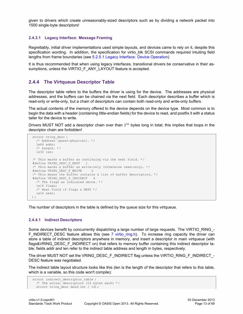
2.4.3.1 Legacy Interface: Message Framing
Regrettably, initial driver implementations used simple layouts, and devices came to rely on it, despite thisspecification wording. In addition, the specification for virtio_blk SCSI commands required intuiting fieldlengths from frame boundaries (see 5.2.5.1 Legacy Interface: Device Operation)
It is thus recommended that when using legacy interfaces, transitional drivers be conservative in their as-sumptions, unless the VIRTIO_F_ANY_LAYOUT feature is accepted.
2.4.4 The Virtqueue Descriptor Table
The descriptor table refers to the buffers the driver is using for the device. The addresses are physicaladdresses, and the buffers can be chained via the next field. Each descriptor describes a buffer which isread-only or write-only, but a chain of descriptors can contain both read-only and write-only buffers.
The actual contents of the memory offered to the device depends on the device type. Most common is tobegin the data with a header (containing little-endian fields) for the device to read, and postfix it with a statustailer for the device to write.
Drivers MUST NOT add a descriptor chain over than 232 bytes long in total; this implies that loops in thedescriptor chain are forbidden!
struct vring_desc {/* Address (guest-physical). */le64 addr;/* Length. */le32 len;
/* This marks a buffer as continuing via the next field. */#define VRING_DESC_F_NEXT 1/* This marks a buffer as write-only (otherwise read-only). */#define VRING_DESC_F_WRITE 2/* This means the buffer contains a list of buffer descriptors. */#define VRING_DESC_F_INDIRECT 4
/* The flags as indicated above. */le16 flags;/* Next field if flags & NEXT */le16 next;
};
The number of descriptors in the table is defined by the queue size for this virtqueue.
2.4.4.1 Indirect Descriptors
Some devices benefit by concurrently dispatching a large number of large requests. The VIRTIO_RING_-F_INDIRECT_DESC feature allows this (see 7 virtio_ring.h). To increase ring capacity the driver canstore a table of indirect descriptors anywhere in memory, and insert a descriptor in main virtqueue (withflags&VRING_DESC_F_INDIRECT on) that refers to memory buffer containing this indirect descriptor ta-ble; fields addr and len refer to the indirect table address and length in bytes, respectively.
The driver MUST NOT set the VRING_DESC_F_INDIRECT flag unless the VIRTIO_RING_F_INDIRECT_-DESC feature was negotiated.
The indirect table layout structure looks like this (len is the length of the descriptor that refers to this table,which is a variable, so this code won't compile):
struct indirect_descriptor_table {/* The actual descriptors (16 bytes each) */struct vring_desc desc[len / 16];
virtio-v1.0-csprd01Standards Track Work Product Copyright © OASIS Open 2013. All Rights Reserved.
03 December 2013Page 13 of 69

};
The first indirect descriptor is located at start of the indirect descriptor table (index 0), additional indirectdescriptors are chained by next field. An indirect descriptor without next field (with flags&VRING_DESC_F_-NEXT off) signals the end of the descriptor. An indirect descriptor can not refer to another indirect descriptortable (flags&VRING_DESC_F_INDIRECT MUST be off). A single indirect descriptor table can include bothread-only and write-only descriptors; the device MUST ignore the write-only flag (flags&VRING_DESC_F_-WRITE) in the descriptor that refers to it.
2.4.5 The Virtqueue Available Ring
struct vring_avail {#define VRING_AVAIL_F_NO_INTERRUPT 1
le16 flags;le16 idx;le16 ring[ /* Queue Size */ ];le16 used_event; /* Only if VIRTIO_RING_F_EVENT_IDX */
};
The available ring refers to what descriptor chains the driver is offering the device: each ring entry refers tothe head of a descriptor chain. It is only written by the driver and read by the device.
The “idx” field indicates where we would put the next descriptor entry in the ring (modulo the queue size).This starts at 0, and increases.
If the VIRTIO_RING_F_INDIRECT_DESC feature bit is not negotiated, the “flags” field offers a crude in-terrupt control mechanism. The driver MUST set this to 0 or 1: 1 indicates that the device SHOULD NOTsend an interrupt when it consumes a descriptor chain from the available ring. The device MUST ignore theused_event value in this case.
Otherwise, if the VIRTIO_RING_F_EVENT_IDX feature bit is negotiated, the driver MUST set the "flags" fieldto 0, and use the “used_event” field in the used ring instead. The driver can ask the device to delay interruptsuntil an entry with an index specified by the “used_event” field is written in the used ring (equivalently, untilthe idx field in the used ring will reach the value used_event + 1).
The driver MUST handle spurious interrupts: either form of interrupt suppression is merely an optimization;it may not suppress interrupts entirely.
2.4.6 The Virtqueue Used Ring
struct vring_used {#define VRING_USED_F_NO_NOTIFY 1
le16 flags;le16 idx;struct vring_used_elem ring[ /* Queue Size */];le16 avail_event; /* Only if VIRTIO_RING_F_EVENT_IDX */
};
/* le32 is used here for ids for padding reasons. */struct vring_used_elem {
/* Index of start of used descriptor chain. */le32 id;/* Total length of the descriptor chain which was used (written to) */le32 len;
};
The used ring is where the device returns buffers once it is done with them: it is only written to by the device,and read by the driver.
Each entry in the ring is a pair: the head entry of the descriptor chain describing the buffer (this matchesan entry placed in the available ring by the guest earlier), and the total of bytes written into the buffer. The
virtio-v1.0-csprd01Standards Track Work Product Copyright © OASIS Open 2013. All Rights Reserved.
03 December 2013Page 14 of 69
latter is extremely useful for drivers using untrusted buffers: if you do not know exactly how much has beenwritten by the device, you usually have to zero the buffer to ensure no data leakage occurs.
If the VIRTIO_RING_F_INDIRECT_DESC feature bit is not negotiated, the “flags” field offers a crude inter-rupt control mechanism. The driver MUST initialize this to 0, the device MUST set this to 0 or 1: 1 indicatesthat the driver SHOULD NOT send an notification when it adds a descriptor chain to the available ring. Thedriver MUST ignore the used_event value in this case.
Otherwise, if the VIRTIO_RING_F_EVENT_IDX feature bit is negotiated, the device MUST leave the "flags"field at 0, and use the “avail_event” field in the used ring instead. The device can ask the driver to delaynotifications until an entry with an index specified by the “avail_event” field is written in the available ring(equivalently, until the idx field in the used ring will reach the value avail_event + 1).
The device MUST handle spurious notification: either form of notification suppression is merely an optimiza-tion; it may not suppress them entirely.
2.4.7 Helpers for Operating Virtqueues
The Linux Kernel Source code contains the definitions above and helper routines in a more usable form, ininclude/linux/virtio_ring.h. This was explicitly licensed by IBM and Red Hat under the (3-clause) BSD licenseso that it can be freely used by all other projects, and is reproduced (with slight variation to remove Linuxassumptions) in 7 virtio_ring.h.
virtio-v1.0-csprd01Standards Track Work Product Copyright © OASIS Open 2013. All Rights Reserved.
03 December 2013Page 15 of 69
3 General Initialization And Device Operation
We start with an overview of device initialization, then expand on the details of the device and how eachstep is preformed. This section should be read along with the bus-specific section which describes how tocommunicate with the specific device.
3.1 Device Initialization
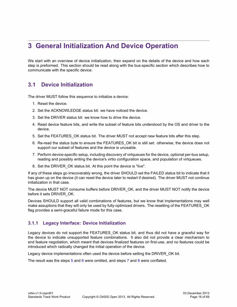
The driver MUST follow this sequence to initialize a device:
1. Reset the device.
2. Set the ACKNOWLEDGE status bit: we have noticed the device.
3. Set the DRIVER status bit: we know how to drive the device.
4. Read device feature bits, and write the subset of feature bits understood by the OS and driver to thedevice.
5. Set the FEATURES_OK status bit. The driver MUST not accept new feature bits after this step.
6. Re-read the status byte to ensure the FEATURES_OK bit is still set: otherwise, the device does notsupport our subset of features and the device is unusable.
7. Perform device-specific setup, including discovery of virtqueues for the device, optional per-bus setup,reading and possibly writing the device's virtio configuration space, and population of virtqueues.
8. Set the DRIVER_OK status bit. At this point the device is "live".
If any of these steps go irrecoverably wrong, the driver SHOULD set the FAILED status bit to indicate that ithas given up on the device (it can reset the device later to restart if desired). The driver MUST not continueinitialization in that case.
The device MUST NOT consume buffers before DRIVER_OK, and the driver MUST NOT notify the devicebefore it sets DRIVER_OK.
Devices SHOULD support all valid combinations of features, but we know that implementations may wellmake assuptions that they will only be used by fully-optimized drivers. The resetting of the FEATURES_OKflag provides a semi-graceful failure mode for this case.
3.1.1 Legacy Interface: Device Initialization
Legacy devices do not support the FEATURES_OK status bit, and thus did not have a graceful way forthe device to indicate unsupported feature combinations. It also did not provide a clear mechanism toend feature negotiation, which meant that devices finalized features on first-use, and no features could beintroduced which radically changed the initial operation of the device.
Legacy device implementations often used the device before setting the DRIVER_OK bit.
The result was the steps 5 and 6 were omitted, and steps 7 and 8 were conflated.
virtio-v1.0-csprd01Standards Track Work Product Copyright © OASIS Open 2013. All Rights Reserved.
03 December 2013Page 16 of 69

3.2 Device Operation
There are two parts to device operation: supplying new buffers to the device, and processing used buffersfrom the device. As an example, the simplest virtio network device has two virtqueues: the transmit virtqueueand the receive virtqueue. The driver adds outgoing (read-only) packets to the transmit virtqueue, and thenfrees them after they are used. Similarly, incoming (write-only) buffers are added to the receive virtqueue,and processed after they are used.
3.2.1 Supplying Buffers to The Device
The driver offers buffers to one of the device's virtqueues as follows:
1. The driver places the buffer into free descriptor(s) in the descriptor table, chaining as necessary (see2.4.4 The Virtqueue Descriptor Table).
2. The driver places the index of the head of the descriptor chain into the next ring entry of the availablering.
3. Steps 1 and 2 may be performed repeatedly if batching is possible.
4. The driver MUST perform suitable a memory barrier to ensure the device sees the updated descriptortable and available ring before the next step.
5. The available “idx” field is increased by the number of descriptor chain heads added to the availablering.
6. The driver MUST perform a suitable memory barrier to ensure that it updates the "idx" field beforechecking for notification suppression.
7. If notifications are not suppressed, the driver MUST notify the device of the new available buffers.
Note that the above code does not take precautions against the available ring buffer wrapping around: thisis not possible since the ring buffer is the same size as the descriptor table, so step (1) will prevent such acondition.
In addition, the maximum queue size is 32768 (it must be a power of 2 which fits in 16 bits), so the 16-bit“idx” value can always distinguish between a full and empty buffer.
Here is a description of each stage in more detail.
3.2.1.1 Placing Buffers Into The Descriptor Table
A buffer consists of zero ormore read-only physically-contiguous elements followed by zero ormore physically-contiguous write-only elements (it must have at least one element). This algorithmmaps it into the descriptortable to form a descriptor chain:
for each buffer element, b:
1. Get the next free descriptor table entry, d
2. Set d.addr to the physical address of the start of b
3. Set d.len to the length of b.
4. If b is write-only, set d.flags to VRING_DESC_F_WRITE, otherwise 0.
5. If there is a buffer element after this:
(a) Set d.next to the index of the next free descriptor element.
(b) Set the VRING_DESC_F_NEXT bit in d.flags.
In practice, the d.next fields are usually used to chain free descriptors, and a separate count kept to checkthere are enough free descriptors before beginning the mappings.
virtio-v1.0-csprd01Standards Track Work Product Copyright © OASIS Open 2013. All Rights Reserved.
03 December 2013Page 17 of 69

3.2.1.2 Updating The Available Ring
The head of the buffer we mapped is the first d in the algorithm above (the descriptor chain head). A naiveimplementation would do the following (with the appropriate conversion to-and-from little-endian assumed):
avail->ring[avail->idx % qsz] = head;
However, in general we can add many descriptor chains before we update the “idx” field (at which point theybecome visible to the device), so we keep a counter of how many we've added:
avail->ring[(avail->idx + added++) % qsz] = head;
3.2.1.3 Updating The Index Field
Once the index field of the virtqueue is updated, the device will be able to access the descriptor chainswe've created and the memory they refer to. This is why a memory barrier is generally used before theindex update, to ensure it sees the most up-to-date copy.
The index field always increments, and we let it wrap naturally at 65536:
avail->idx += added;
3.2.1.4 Notifying The Device
The actual method of device notification is bus-specific, but generally it can be expensive. So the devicecan suppress such notifications if it doesn't need them. The driver has to be careful to expose the new indexvalue before checking if notifications are suppressed: it's OK to notify gratuitously, but not to omit a requirednotification. So again, we use a memory barrier here before reading the flags or the avail_event field.
If the VIRTIO_F_RING_EVENT_IDX feature is not negotiated, and if the VRING_USED_F_NOTIFY flag isnot set, we go ahead and notify the device.
If the VIRTIO_F_RING_EVENT_IDX feature is negotiated, we read the avail_event field in the available ringstructure. If the available index crossed_the avail_event field value since the last notification, we go aheadand write to the PCI configuration space. The avail_event field wraps naturally at 65536 as well, iving thefollowing algorithm for calculating whether a device needs notification:
(u16)(new_idx - avail_event - 1) < (u16)(new_idx - old_idx)
3.2.2 Receiving Used Buffers From The Device
Once the device has used a buffer (read from or written to it, or parts of both, depending on the nature ofthe virtqueue and the device), it sends an interrupt, following an algorithm very similar to the algorithm usedfor the driver to send the device a buffer:
1. Write the head descriptor number to the next field in the used ring.
2. Update the used ring index.
3. Deliver an interrupt if necessary:
(a) If the VIRTIO_F_RING_EVENT_IDX feature is not negotiated: check if the VRING_AVAIL_F_-NO_INTERRUPT flag is not set in avail->flags.
(b) If the VIRTIO_F_RING_EVENT_IDX feature is negotiated: check whether the used index crossedthe used_event field value since the last update. The used_event field wraps naturally at 65536as well:
(u16)(new_idx - used_event - 1) < (u16)(new_idx - old_idx)
virtio-v1.0-csprd01Standards Track Work Product Copyright © OASIS Open 2013. All Rights Reserved.
03 December 2013Page 18 of 69
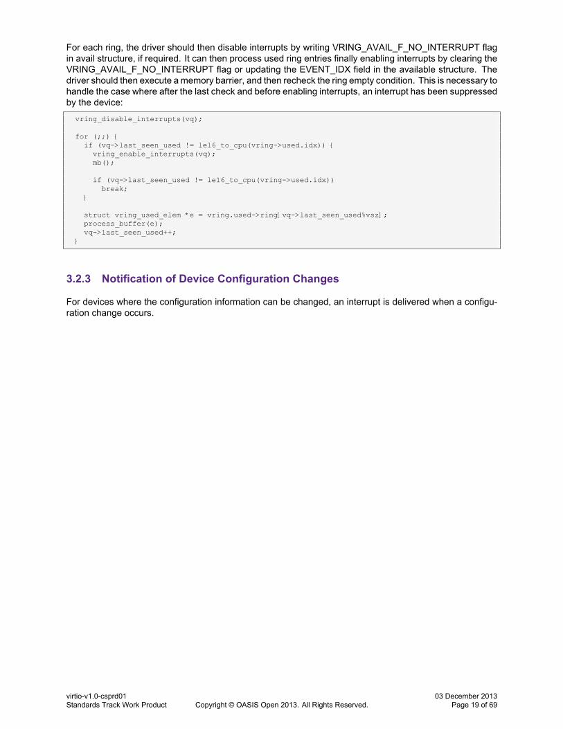
For each ring, the driver should then disable interrupts by writing VRING_AVAIL_F_NO_INTERRUPT flagin avail structure, if required. It can then process used ring entries finally enabling interrupts by clearing theVRING_AVAIL_F_NO_INTERRUPT flag or updating the EVENT_IDX field in the available structure. Thedriver should then execute amemory barrier, and then recheck the ring empty condition. This is necessary tohandle the case where after the last check and before enabling interrupts, an interrupt has been suppressedby the device:
vring_disable_interrupts(vq);
for (;;) {if (vq->last_seen_used != le16_to_cpu(vring->used.idx)) {vring_enable_interrupts(vq);mb();
if (vq->last_seen_used != le16_to_cpu(vring->used.idx))break;
}
struct vring_used_elem *e = vring.used->ring[vq->last_seen_used%vsz];process_buffer(e);vq->last_seen_used++;
}
3.2.3 Notification of Device Configuration Changes
For devices where the configuration information can be changed, an interrupt is delivered when a configu-ration change occurs.
virtio-v1.0-csprd01Standards Track Work Product Copyright © OASIS Open 2013. All Rights Reserved.
03 December 2013Page 19 of 69

4 Virtio Transport Options
Virtio can use various different busses, thus the standard is split into virtio general and bus-specific sections.
4.1 Virtio Over PCI Bus
Virtio devices are commonly implemented as PCI devices.
4.1.1 PCI Device Discovery
Any PCI device with Vendor ID 0x1AF4, and Device ID 0x1000 through 0x103F inclusive is a virtio device1.
The Subsystem Device ID indicates which virtio device is supported by the device. The Subsystem VendorID SHOULD reflect the PCI Vendor ID of the environment (it's currently only used for informational purposesby the driver).
All driversMUSTmatch devices with any Revision ID, this is to allow devices to be versionedwithout breakingdrivers.
4.1.1.1 Legacy Interfaces: A Note on PCI Device Discovery
Transitional devices must have a Revision ID of 0 to match legacy drivers.
Non-transitional devices must have a Revision ID of 1 or higher.
Both transitional and non-transitional drivers must match any Revision ID value.
4.1.2 PCI Device Layout
To configure the device, use I/O and/or memory regions and/or PCI configuration space of the PCI device.These contain the virtio header registers, the notification register, the ISR status register and device specificregisters, as specified by Virtio Structure PCI Capabilities.
There may be different widths of accesses to the I/O region; the “natural” access method for each field mustbe used (i.e. 32-bit accesses for 32-bit fields, etc).
PCI Device Configuration Layout includes the common configuration, ISR, notification and device specificconfiguration structures.
All multi-byte fields are little-endian.
4.1.2.1 Common configuration structure layout
Common configuration structure layout is documented below:1The actual value within this range is ignored
virtio-v1.0-csprd01Standards Track Work Product Copyright © OASIS Open 2013. All Rights Reserved.
03 December 2013Page 20 of 69

struct virtio_pci_common_cfg {/* About the whole device. */le32 device_feature_select; /* read-write */le32 device_feature; /* read-only */le32 driver_feature_select; /* read-write */le32 driver_feature; /* read-write */le16 msix_config; /* read-write */le16 num_queues; /* read-only */u8 device_status; /* read-write */u8 config_generation; /* read-only */
/* About a specific virtqueue. */le16 queue_select; /* read-write */le16 queue_size; /* read-write, power of 2, or 0. */le16 queue_msix_vector; /* read-write */le16 queue_enable; /* read-write */le16 queue_notify_off; /* read-only */le64 queue_desc; /* read-write */le64 queue_avail; /* read-write */le64 queue_used; /* read-write */
};
device_feature_select The driver uses this to select which Feature Bits the device_feature field shows.Value 0x0 selects Feature Bits 0 to 31 Value 0x1 selects Feature Bits 32 to 63 The device MUSTpresent 0 on device_feature for any other value.
device_feature The device uses this to report Feature Bits to the driver. Device Feature Bits selected bydevice_feature_select.
driver_feature_select The driver uses this to select which Feature Bits the driver_feature field shows.Value 0x0 selects Feature Bits 0 to 31 Value 0x1 selects Feature Bits 32 to 63 When set to any othervalue, reads from driver_feature return 0, writing 0 into driver_feature has no effect. The driver MUSTnot write any other value into driver_feature (a corollary of the rule that the driver can only write asubset of device features).
driver_feature The driver writes this to accept feature bits offered by the device. Driver Feature Bits se-lected by driver_feature_select.
msix_config The driver sets the Configuration Vector for MSI-X.
num_queues The device specifies the maximum number of virtqueues supported here.
device_status The driver writes the Device Status here. Writing 0 into this field resets the device.
config_generation Configuration atomicity value. The device changes this every time the configurationnoticeably changes. This means the device may only change the value after a configuration readoperation, but MUST change it if there is any risk of a driver seeing an inconsistent configuration state.
queue_select Queue Select. The driver selects which virtqueue the following fields refer to.
queue_size Queue Size. On reset, specifies the maximum queue size supported by the hypervisor. Thiscan be modified by driver to reduce memory requirements. The device MUST set this to 0 if thisvirtqueue is unavailable.
queue_msix_vector The driver uses this to specify the Queue Vector for MSI-X.
queue_enable The driver uses this to selectively prevent the device from executing requests from thisvirtqueue. 1 - enabled; 0 - disabled
The driver MUST configure the other virtqueue fields before enabling the virtqueue.
queue_notify_off The driver reads this to calculate the offset from start of Notification structure at whichthis virtqueue is located. Note: this is *not* an offset in bytes. See notify_off_multiplier below.
queue_desc The driver writes the physical address of Descriptor Table here.
queue_avail The driver writes the physical address of Available Ring here.
virtio-v1.0-csprd01Standards Track Work Product Copyright © OASIS Open 2013. All Rights Reserved.
03 December 2013Page 21 of 69

queue_used The driver writes the physical address of Used Ring here.
4.1.2.2 ISR status structure layout
ISR status structure includes a single 8-bit ISR status field.
4.1.2.3 Notification structure layout
Notification structure is always a multiple of 2 bytes in size. It includes 2-byte Queue Notify fields for eachvirtqueue of the device. Note that multiple virtqueues can use the same Queue Notify field, if necessary:see notify_off_multiplier below.
4.1.2.4 Device specific structure
Device specific structure is optional.
4.1.2.5 Legacy Interfaces: A Note on PCI Device Layout
Transitional devices should present part of configuration registers in a legacy configuration structure in BAR0in the first I/O region of the PCI device, as documented below.
There may be different widths of accesses to the I/O region; the “natural” access method for each field inthe virtio header must be used (i.e. 32-bit accesses for 32-bit fields, etc), but when accessed through thelegacy interface the device-specific region can be accessed using any width accesses, and should obtainthe same results.
Note that this is possible because while the virtio header is PCI (i.e. little) endian, when using the legacyinterface the device-specific region is encoded in the native endian of the guest (where such distinction isapplicable).
When used through the legacy interface, the virtio header looks as follows:
Bits 32 32 32 16 16 16 8 8Read /Write
R R+W R+W R R+W R+W R+W R
Purpose DeviceFeaturesbits 0:31
DriverFeaturesbits 0:31
QueueSize
QueueSelect
QueueNotify
QueueAddress
DeviceStatus
ISRStatus
If MSI-X is enabled for the device, two additional fields immediately follow this header:
Bits 16 16Read/Write R+W R+WPurpose (MSI-X) Configuration Vector Queue Vector
Note: When MSI-X capability is enabled, device specific configuration starts at byte offset 24 in virtio headerstructure. When MSI-X capability is not enabled, device specific configuration starts at byte offset 20 in virtioheader. ie. once you enable MSI-X on the device, the other fields move. If you turn it off again, they moveback!
Immediately following these general headers, there may be device-specific headers:
Bits Device Specific...Read / Write Device Specific
Purpose Device Specific
virtio-v1.0-csprd01Standards Track Work Product Copyright © OASIS Open 2013. All Rights Reserved.
03 December 2013Page 22 of 69

Note that only Feature Bits 0 to 31 are accessible through the Legacy Interface. When used through theLegacy Interface, Transitional Devices must assume that Feature Bits 32 to 63 are not acknowledged byDriver.
As legacy devices had no configuration generation field, see 2.3.2 Legacy Interface: Configuration Spacefor workarounds.
4.1.3 PCI-specific Initialization And Device Operation
4.1.3.1 Device Initialization
This documents PCI-specific steps executed during Device Initialization. As the first step, driver must detectdevice configuration layout to locate configuration fields in memory, I/O or configuration space of the device.
4.1.3.1.1 Virtio Device Configuration Layout Detection
As a prerequisite to device initialization, driver executes a PCI capability list scan, detecting virtio configu-ration layout using Virtio Structure PCI capabilities.
Virtio Device Configuration Layout includes virtio configuration header, Notification and ISR Status anddevice configuration structures. Each structure can be mapped by a Base Address register (BAR) belongingto the function, located beginning at 10h in Configuration Space, or accessed though PCI configurationspace.
Actual location of each structure is specified using vendor-specific PCI capability located on capability listin PCI configuration space of the device. This virtio structure capability uses little-endian format; all bits areread-only:
struct virtio_pci_cap {u8 cap_vndr; /* Generic PCI field: PCI_CAP_ID_VNDR */u8 cap_next; /* Generic PCI field: next ptr. */u8 cap_len; /* Generic PCI field: capability length */u8 cfg_type; /* Identifies the structure. */u8 bar; /* Where to find it. */u8 padding[3]; /* Pad to full dword. */le32 offset; /* Offset within bar. */le32 length; /* Length of the structure, in bytes. */
};
This structure can optionally followed by extra data, depending on other fields, as documented below.
Note that future versions of this specification will likely extend devices by adding extra fields at the tail endof some structures.
To allow forward compatibility with such extensions, drivers must not limit structure size. Instead, driversshould only check that structures are *large enough* to contain the fields required for device operation.
For example, if the specification states 'structure includes a single 8-bit field' drivers should understand thisto mean that the structure can also include an arbitrary amount of tail padding, and accept any structuresize equal to or greater than the specified 8-bit size.
The fields are interpreted as follows:
cap_vndr 0x09; Identifies a vendor-specific capability.
cap_next Link to next capability in the capability list in the configuration space.
cap_len Length of the capability structure, including the whole of struct virtio_pci_cap, and extra data ifany. This length might include padding, or fields unused by the driver.
cfg_type identifies the structure, according to the following table.
virtio-v1.0-csprd01Standards Track Work Product Copyright © OASIS Open 2013. All Rights Reserved.
03 December 2013Page 23 of 69
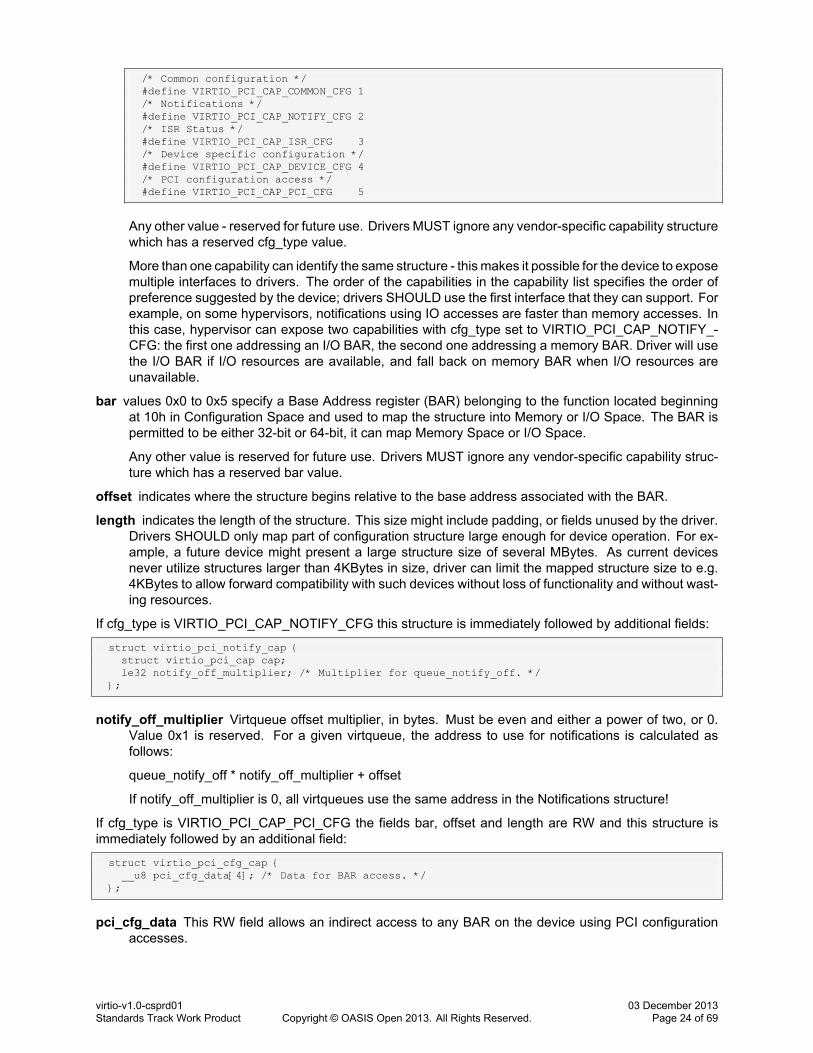
/* Common configuration */#define VIRTIO_PCI_CAP_COMMON_CFG 1/* Notifications */#define VIRTIO_PCI_CAP_NOTIFY_CFG 2/* ISR Status */#define VIRTIO_PCI_CAP_ISR_CFG 3/* Device specific configuration */#define VIRTIO_PCI_CAP_DEVICE_CFG 4/* PCI configuration access */#define VIRTIO_PCI_CAP_PCI_CFG 5
Any other value - reserved for future use. Drivers MUST ignore any vendor-specific capability structurewhich has a reserved cfg_type value.
More than one capability can identify the same structure - this makes it possible for the device to exposemultiple interfaces to drivers. The order of the capabilities in the capability list specifies the order ofpreference suggested by the device; drivers SHOULD use the first interface that they can support. Forexample, on some hypervisors, notifications using IO accesses are faster than memory accesses. Inthis case, hypervisor can expose two capabilities with cfg_type set to VIRTIO_PCI_CAP_NOTIFY_-CFG: the first one addressing an I/O BAR, the second one addressing a memory BAR. Driver will usethe I/O BAR if I/O resources are available, and fall back on memory BAR when I/O resources areunavailable.
bar values 0x0 to 0x5 specify a Base Address register (BAR) belonging to the function located beginningat 10h in Configuration Space and used to map the structure into Memory or I/O Space. The BAR ispermitted to be either 32-bit or 64-bit, it can map Memory Space or I/O Space.
Any other value is reserved for future use. Drivers MUST ignore any vendor-specific capability struc-ture which has a reserved bar value.
offset indicates where the structure begins relative to the base address associated with the BAR.
length indicates the length of the structure. This size might include padding, or fields unused by the driver.Drivers SHOULD only map part of configuration structure large enough for device operation. For ex-ample, a future device might present a large structure size of several MBytes. As current devicesnever utilize structures larger than 4KBytes in size, driver can limit the mapped structure size to e.g.4KBytes to allow forward compatibility with such devices without loss of functionality and without wast-ing resources.
If cfg_type is VIRTIO_PCI_CAP_NOTIFY_CFG this structure is immediately followed by additional fields:
struct virtio_pci_notify_cap {struct virtio_pci_cap cap;le32 notify_off_multiplier; /* Multiplier for queue_notify_off. */
};
notify_off_multiplier Virtqueue offset multiplier, in bytes. Must be even and either a power of two, or 0.Value 0x1 is reserved. For a given virtqueue, the address to use for notifications is calculated asfollows:
queue_notify_off * notify_off_multiplier + offset
If notify_off_multiplier is 0, all virtqueues use the same address in the Notifications structure!
If cfg_type is VIRTIO_PCI_CAP_PCI_CFG the fields bar, offset and length are RW and this structure isimmediately followed by an additional field:
struct virtio_pci_cfg_cap {__u8 pci_cfg_data[4]; /* Data for BAR access. */
};
pci_cfg_data This RW field allows an indirect access to any BAR on the device using PCI configurationaccesses.
virtio-v1.0-csprd01Standards Track Work Product Copyright © OASIS Open 2013. All Rights Reserved.
03 December 2013Page 24 of 69

The BAR to access is selected using the bar field. The length of the access is specified by the lengthfield, which can be set to 1, 2 and 4. The offset within the BAR is specified by the offset field, whichmust be aligned to length bytes.
After this field is written by driver, the first length bytes in pci_cfg_data are written at the selected offsetin the selected BAR.
When this field is read by driver, length bytes at the selected offset in the selected BAR are read intopci_cfg_data.
4.1.3.1.1.1 Legacy Interface: A Note on Device Layout Detection
Legacy drivers skipped Device Layout Detection step, assuming legacy configuration space in BAR0 in I/Ospace unconditionally.
Legacy devices did not have the Virtio PCI Capability in their capability list.
Therefore:
Transitional devices should expose the Legacy Interface in I/O space in BAR0.
Transitional drivers should look for the Virtio PCI Capabilities on the capability list. If these are not present,driver should assume a legacy device.
Non-transitional drivers should look for the Virtio PCI Capabilities on the capability list. If these are notpresent, driver should assume a legacy device, and fail gracefully.
Non-transitional devices, on a platform where a legacy driver for a legacy device with the same ID mighthave previously existed, must take the following steps to fail gracefully when a legacy driver attempts todrive them:
1. Present an I/O BAR in BAR0, and
2. Respond to a single-byte zero write to offset 18 (corresponding to Device Status register in the legacylayout) of BAR0 by presenting zeroes on every BAR and ignoring writes.
4.1.3.1.2 Queue Vector Configuration
When MSI-X capability is present and enabled in the device (through standard PCI configuration space)Configuration/Queue MSI-X Vector registers are used to map configuration change and queue interrupts toMSI-X vectors. In this case, the ISR Status is unused.
Writing a valid MSI-X Table entry number, 0 to 0x7FF, to one of Configuration/Queue Vector registers, mapsinterrupts triggered by the configuration change/selected queue events respectively to the correspondingMSI-X vector. To disable interrupts for a specific event type, unmap it by writing a special NO_VECTORvalue:
/* Vector value used to disable MSI for queue */#define VIRTIO_MSI_NO_VECTOR 0xffff
Reading these registers returns vector mapped to a given event, or NO_VECTOR if unmapped. All queueand configuration change events are unmapped by default.
Note that mapping an event to vector might require allocating internal device resources, and might fail.Devices MUST report such failures by returning the NO_VECTOR value when the relevant Vector field isread. After mapping an event to vector, the driver MUST verify success by reading the Vector field value:on success, the previously written value is returned, and on failure, NO_VECTOR is returned. If a mappingfailure is detected, the driver can retry mapping with fewer vectors, or disable MSI-X.
virtio-v1.0-csprd01Standards Track Work Product Copyright © OASIS Open 2013. All Rights Reserved.
03 December 2013Page 25 of 69

4.1.3.1.3 Virtqueue Configuration
As a device can have zero or more virtqueues for bulk data transport (for example, the simplest networkdevice has two), the driver needs to configure them as part of the device-specific configuration.
The driver does this as follows, for each virtqueue a device has:
1. Write the virtqueue index (first queue is 0) to the Queue Select field.
2. Read the virtqueue size from the Queue Size field, which MUST be a power of 2. This controls howbig the virtqueue is (see 2.4 Virtqueues). If this field is 0, the virtqueue does not exist.
3. Optionally, select a smaller virtqueue size and write it in the Queue Size field.
4. Allocate and zero Descriptor Table, Available and Used rings for the virtqueue in contiguous physicalmemory.
5. Optionally, if MSI-X capability is present and enabled on the device, select a vector to use to requestinterrupts triggered by virtqueue events. Write the MSI-X Table entry number corresponding to thisvector in Queue Vector field. Read the Queue Vector field: on success, previously written value isreturned; on failure, NO_VECTOR value is returned.
4.1.3.1.3.1 Legacy Interface: A Note on Virtqueue Configuration
When using the legacy interface, the page size for a virtqueue on a PCI virtio device is defined as 4096bytes. Driver writes the physical address, divided by 4096 to the Queue Address field2.
4.1.3.2 Notifying The Device
Device notification occurs by writing the 16-bit virtqueue index of this virtqueue to the Queue Notify field.
4.1.3.3 Virtqueue Interrupts From The Device
If an interrupt is necessary:
• If MSI-X capability is disabled:
1. Set the lower bit of the ISR Status field for the device.
2. Send the appropriate PCI interrupt for the device.
• If MSI-X capability is enabled:
1. Request the appropriate MSI-X interrupt message for the device, Queue Vector field sets theMSI-X Table entry number.
2. If Queue Vector field value is NO_VECTOR, no interrupt message is requested for this event.
The driver interrupt handler should:
• If MSI-X capability is disabled: read the ISR Status field, which will reset it to zero. If the lower bit iszero, the interrupt was not for this device. Otherwise, the driver should look through the used ringsof each virtqueue for the device, to see if any progress has been made by the device which requiresservicing.
• If MSI-X capability is enabled: look through the used rings of each virtqueue mapped to the specificMSI-X vector for the device, to see if any progress has been made by the device which requiresservicing.
2The 4096 is based on the x86 page size, but it's also large enough to ensure that the separate parts of the virtqueue are on separatecache lines.
virtio-v1.0-csprd01Standards Track Work Product Copyright © OASIS Open 2013. All Rights Reserved.
03 December 2013Page 26 of 69

4.1.3.4 Notification of Device Configuration Changes
Some virtio PCI devices can change the device configuration state, as reflected in the virtio header in thePCI configuration space. In this case:
• If MSI-X capability is disabled: an interrupt is delivered and the second lowest bit is set in the ISRStatus field to indicate that the driver should re-examine the configuration space. Note that a singleinterrupt can indicate both that one or more virtqueue has been used and that the configuration spacehas changed: even if the config bit is set, virtqueues must be scanned.
• If MSI-X capability is enabled: an interrupt message is requested. The Configuration Vector field setsthe MSI-X Table entry number to use. If Configuration Vector field value is NO_VECTOR, no interruptmessage is requested for this event.
4.2 Virtio Over MMIO
Virtual environments without PCI support (a common situation in embedded devices models) might usesimple memory mapped device ("virtio-mmio") instead of the PCI device.
The memory mapped virtio device behaviour is based on the PCI device specification. Therefore most ofoperations like device initialization, queues configuration and buffer transfers are nearly identical. Existingdifferences are described in the following sections.
4.2.1 MMIO Device Discovery
Unlike PCI, MMIO provides no generic device discovery. For systems using Flattened Device Trees thesuggested format is:
virtio_block@1e000 {compatible = "virtio,mmio";reg = <0x1e000 0x100>;interrupts = <42>;
}
4.2.2 MMIO Device Layout
MMIO virtio devices provides a set of memory mapped control registers, all 32 bits wide, followed by device-specific configuration space. The following table presents their names, offset from the base address, andwhether they are read-only (R) or write-only (W) from the driver's perspective:
MagicValue (0x000) - R Magic value. Must be 0x74726976 (a Little Endian equivalent of a "virt" string).
Version (0x004) - R Device version number. Devices compliant with this specification must return value0x2.
DeviceID (0x008) - R Virtio Subsystem Device ID. See 5 Device Types for possible values. Value zero(0x0) is invalid and devices returning this ID must be ignored by the guest.
VendorID (0x00c) - R Virtio Subsystem Vendor ID.
DeviceFeatures (0x010) - R Flags representing features the device supports. Reading from this registerreturns 32 consecutive flag bits, first bit depending on the last value written to the DeviceFeaturesSelregister. Access to this register returns bits DeviceFeaturesSel*32 to (DeviceFeaturesSel*32)+31, eg.feature bits 0 to 31 if DeviceFeaturesSel is set to 0 and features bits 32 to 63 if DeviceFeaturesSel isset to 1. Also see 2.2 Feature Bits.
DeviceFeaturesSel (0x014) - W Device (host) features word selection. Writing to this register selects a setof 32 device feature bits accessible by reading from the DeviceFeatures register. Device driver mustwrite a value to the DeviceFeaturesSel register before reading from the DeviceFeatures register.
virtio-v1.0-csprd01Standards Track Work Product Copyright © OASIS Open 2013. All Rights Reserved.
03 December 2013Page 27 of 69
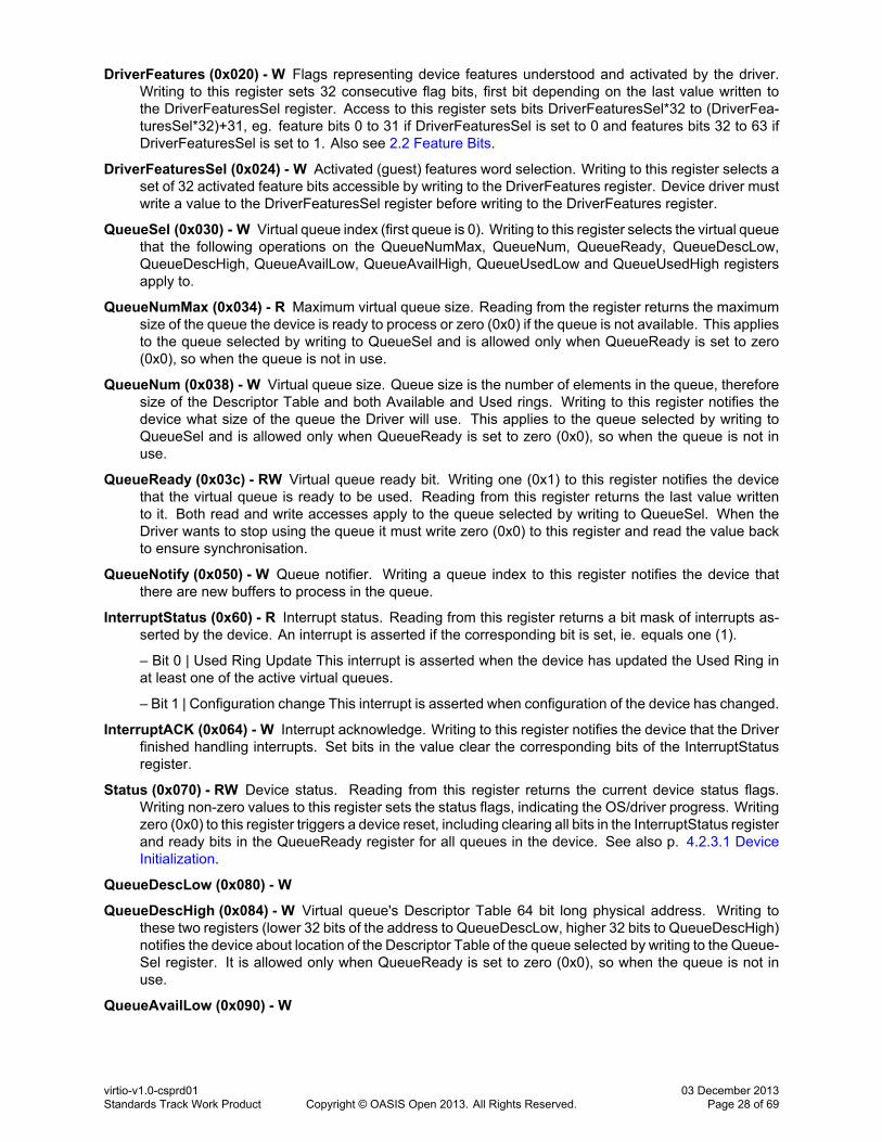
DriverFeatures (0x020) - W Flags representing device features understood and activated by the driver.Writing to this register sets 32 consecutive flag bits, first bit depending on the last value written tothe DriverFeaturesSel register. Access to this register sets bits DriverFeaturesSel*32 to (DriverFea-turesSel*32)+31, eg. feature bits 0 to 31 if DriverFeaturesSel is set to 0 and features bits 32 to 63 ifDriverFeaturesSel is set to 1. Also see 2.2 Feature Bits.
DriverFeaturesSel (0x024) - W Activated (guest) features word selection. Writing to this register selects aset of 32 activated feature bits accessible by writing to the DriverFeatures register. Device driver mustwrite a value to the DriverFeaturesSel register before writing to the DriverFeatures register.
QueueSel (0x030) - W Virtual queue index (first queue is 0). Writing to this register selects the virtual queuethat the following operations on the QueueNumMax, QueueNum, QueueReady, QueueDescLow,QueueDescHigh, QueueAvailLow, QueueAvailHigh, QueueUsedLow and QueueUsedHigh registersapply to.
QueueNumMax (0x034) - R Maximum virtual queue size. Reading from the register returns the maximumsize of the queue the device is ready to process or zero (0x0) if the queue is not available. This appliesto the queue selected by writing to QueueSel and is allowed only when QueueReady is set to zero(0x0), so when the queue is not in use.
QueueNum (0x038) - W Virtual queue size. Queue size is the number of elements in the queue, thereforesize of the Descriptor Table and both Available and Used rings. Writing to this register notifies thedevice what size of the queue the Driver will use. This applies to the queue selected by writing toQueueSel and is allowed only when QueueReady is set to zero (0x0), so when the queue is not inuse.
QueueReady (0x03c) - RW Virtual queue ready bit. Writing one (0x1) to this register notifies the devicethat the virtual queue is ready to be used. Reading from this register returns the last value writtento it. Both read and write accesses apply to the queue selected by writing to QueueSel. When theDriver wants to stop using the queue it must write zero (0x0) to this register and read the value backto ensure synchronisation.
QueueNotify (0x050) - W Queue notifier. Writing a queue index to this register notifies the device thatthere are new buffers to process in the queue.
InterruptStatus (0x60) - R Interrupt status. Reading from this register returns a bit mask of interrupts as-serted by the device. An interrupt is asserted if the corresponding bit is set, ie. equals one (1).
– Bit 0 | Used Ring Update This interrupt is asserted when the device has updated the Used Ring inat least one of the active virtual queues.
– Bit 1 | Configuration change This interrupt is asserted when configuration of the device has changed.
InterruptACK (0x064) - W Interrupt acknowledge. Writing to this register notifies the device that the Driverfinished handling interrupts. Set bits in the value clear the corresponding bits of the InterruptStatusregister.
Status (0x070) - RW Device status. Reading from this register returns the current device status flags.Writing non-zero values to this register sets the status flags, indicating the OS/driver progress. Writingzero (0x0) to this register triggers a device reset, including clearing all bits in the InterruptStatus registerand ready bits in the QueueReady register for all queues in the device. See also p. 4.2.3.1 DeviceInitialization.
QueueDescLow (0x080) - W
QueueDescHigh (0x084) - W Virtual queue's Descriptor Table 64 bit long physical address. Writing tothese two registers (lower 32 bits of the address to QueueDescLow, higher 32 bits to QueueDescHigh)notifies the device about location of the Descriptor Table of the queue selected by writing to the Queue-Sel register. It is allowed only when QueueReady is set to zero (0x0), so when the queue is not inuse.
QueueAvailLow (0x090) - W
virtio-v1.0-csprd01Standards Track Work Product Copyright © OASIS Open 2013. All Rights Reserved.
03 December 2013Page 28 of 69

QueueAvailHigh (0x094) - W Virtual queue's Available Ring 64 bit long physical address. Writing to thesetwo registers (lower 32 bits of the address to QueueAvailLow, higher 32 bits to QueueAvailHigh) noti-fies the device about location of the Available Ring of the queue selected by writing to the QueueSelregister. It is allowed only when QueueReady is set to zero (0x0), so when the queue is not in use.
QueueUsedLow (0x0a0) - W
QueueUsedHigh (0x0a4) - W Virtual queue's Used Ring 64 bit long physical address. Writing to these tworegisters (lower 32 bits of the address to QueueUsedLow, higher 32 bits to QueueUsedHigh) notifiesthe device about location of the Used Ring of the queue selected by writing to the QueueSel register.It is allowed only when QueueReady is set to zero (0x0), so when the queue is not in use.
ConfigGeneration (0x0fc) - R Configuration atomicity value. Changes every time the configuration notice-ably changes. This means the device may only change the value after a configuration read operation,but it must change if there is any risk of a device seeing an inconsistent configuration state.
Config (0x100) - RW Device-specific configuration space starts at an offset 0x100 and is accessed withbyte alignment. Its meaning and size depends on the device and the driver.
All register values are organized as Little Endian.
Accessing memory locations not explicitly described above (or - in case of the configuration space - de-scribed in the device specification), writing to the registers described as "R" and reading from registersdescribed as "W" is not permitted and can cause undefined behavior.
4.2.3 MMIO-specific Initialization And Device Operation
4.2.3.1 Device Initialization
The driver must start the device initialization by reading and checking values from the MagicValue and theVersion registers. If both values are valid, it must read the DeviceID register and if its value is zero (0x0)must abort initialization and must not access any other register.
Further initialization must follow the procedure described in 3.1 Device Initialization.
4.2.3.2 Virtqueue Configuration
1. Select the queue writing its index (first queue is 0) to the QueueSel register.
2. Check if the queue is not already in use: read the QueueReady register, returned value should bezero (0x0).
3. Read maximum queue size (number of elements) from the QueueNumMax register. If the returnedvalue is zero (0x0) the queue is not available.
4. Allocate and zero the queue pages, making sure the memory is physically contiguous. It is recom-mended to align the Used Ring to an optimal boundary (usually page size). Size of the allocated queuemay be smaller than or equal to the maximum size returned by the device.
5. Notify the device about the queue size by writing the size to the QueueNum register.
6. Write physical addresses of the queue's Descriptor Table, Available Ring and Used Ring to (respec-tively) the QueueDescLow/ QueueDescHigh, QueueAvailLow/QueueAvailHigh and QueueUsedLow/QueueUsedHigh register pairs.
7. Write 0x1 to the QueueReady register.
4.2.3.3 Notifying The Device
The device is notified about new buffers available in a queue by writing the queue index to the QueueNumregister.
virtio-v1.0-csprd01Standards Track Work Product Copyright © OASIS Open 2013. All Rights Reserved.
03 December 2013Page 29 of 69
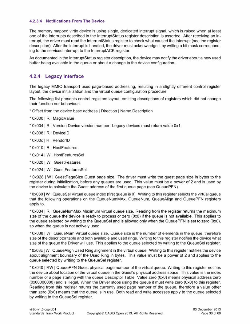
4.2.3.4 Notifications From The Device
The memory mapped virtio device is using single, dedicated interrupt signal, which is raised when at leastone of the interrupts described in the InterruptStatus register description is asserted. After receiving an in-terrupt, the driver must read the InterruptStatus register to check what caused the interrupt (see the registerdescription). After the interrupt is handled, the driver must acknowledge it by writing a bit mask correspond-ing to the serviced interrupt to the InterruptACK register.
As documented in the InterruptStatus register description, the device may notify the driver about a new usedbuffer being available in the queue or about a change in the device configuration.
4.2.4 Legacy interface
The legacy MMIO transport used page-based addressing, resulting in a slightly different control registerlayout, the device initialization and the virtual queue configuration procedure.
The following list presents control registers layout, omitting descriptions of registers which did not changetheir function nor behaviour:
* Offset from the device base address | Direction | Name Description
* 0x000 | R | MagicValue
* 0x004 | R | Version Device version number. Legacy devices must return value 0x1.
* 0x008 | R | DeviceID
* 0x00c | R | VendorID
* 0x010 | R | HostFeatures
* 0x014 | W | HostFeaturesSel
* 0x020 | W | GuestFeatures
* 0x024 | W | GuestFeaturesSel
* 0x028 | W | GuestPageSize Guest page size. The driver must write the guest page size in bytes to theregister during initialization, before any queues are used. This value must be a power of 2 and is used bythe device to calculate the Guest address of the first queue page (see QueuePFN).
* 0x030 | W | QueueSel Virtual queue index (first queue is 0). Writing to this register selects the virtual queuethat the following operations on the QueueNumMAx, QueueNum, QueueAlign and QueuePFN registersapply to.
* 0x034 | R | QueueNumMax Maximum virtual queue size. Reading from the register returns the maximumsize of the queue the device is ready to process or zero (0x0) if the queue is not available. This applies tothe queue selected by writing to the QueueSel and is allowed only when the QueuePFN is set to zero (0x0),so when the queue is not actively used.
* 0x038 | W | QueueNum Virtual queue size. Queue size is the number of elements in the queue, thereforesize of the descriptor table and both available and used rings. Writing to this register notifies the device whatsize of the queue the Driver will use. This applies to the queue selected by writing to the QueueSel register.
* 0x03c | W | QueueAlign Used Ring alignment in the virtual queue. Writing to this register notifies the deviceabout alignment boundary of the Used Ring in bytes. This value must be a power of 2 and applies to thequeue selected by writing to the QueueSel register.
* 0x040 | RW | QueuePFN Guest physical page number of the virtual queue. Writing to this register notifiesthe device about location of the virtual queue in the Guest's physical address space. This value is the indexnumber of a page starting with the queue Descriptor Table. Value zero (0x0) means physical address zero(0x00000000) and is illegal. When the Driver stops using the queue it must write zero (0x0) to this register.Reading from this register returns the currently used page number of the queue, therefore a value otherthan zero (0x0) means that the queue is in use. Both read and write accesses apply to the queue selectedby writing to the QueueSel register.
virtio-v1.0-csprd01Standards Track Work Product Copyright © OASIS Open 2013. All Rights Reserved.
03 December 2013Page 30 of 69

* 0x050 | W | QueueNotify
* 0x060 | R | InterruptStatus
* 0x064 | W | InterruptACK
* 0x070 | RW | Status Device status. Reading from this register returns the current device status flags.Writing non-zero values to this register sets the status flags, indicating the OS/driver progress. Writing zero(0x0) to this register triggers a device reset. This should include setting QueuePFN to zero (0x0) for allqueues in the device. Also see 3.1 Device Initialization.
* 0x100+ | RW | Config
The virtual queue page size is defined by writing to the GuestPageSize register, as written by the guest.This must be done before the virtual queues are configured.
The virtual queue layout follows p. 2.4.1 Legacy Interfaces: A Note on Virtqueue Layout, with the alignmentdefined in the QueueAlign register.
The virtual queue is configured as follows:
1. Select the queue writing its index (first queue is 0) to the QueueSel register.
2. Check if the queue is not already in use: read the QueuePFN register, returned value should be zero(0x0).
3. Read maximum queue size (number of elements) from the QueueNumMax register. If the returnedvalue is zero (0x0) the queue is not available.
4. Allocate and zero the queue pages in contiguous virtual memory, aligning the Used Ring to an opti-mal boundary (usually page size). Size of the allocated queue may be smaller than or equal to themaximum size returned by the device.
5. Notify the device about the queue size by writing the size to the QueueNum register.
6. Notify the device about the used alignment by writing its value in bytes to the QueueAlign register.
7. Write the physical number of the first page of the queue to the QueuePFN register.
Notification mechanisms did not change.
4.3 Virtio Over Channel I/O
S/390 based virtual machines support neither PCI nor MMIO, so a different transport is needed there.
virtio-ccw uses the standard channel I/O based mechanism used for the majority of devices on S/390. Avirtual channel device with a special control unit type acts as proxy to the virtio device (similar to the wayvirtio-pci uses a PCI device) and configuration and operation of the virtio device is accomplished (mostly) viachannel commands. This means virtio devices are discoverable via standard operating system algorithms,and adding virtio support is mainly a question of supporting a new control unit type.
As the S/390 is a big endian machine, the data structures transmitted via channel commands are big-endian:this is made clear by use of the types be16, be32 and be64.
4.3.1 Basic Concepts
As a proxy device, virtio-ccw uses a channel-attached I/O control unit with a special control unit type (0x3832)and a control unit model corresponding to the attached virtio device's subsystem device ID, accessed viaa virtual I/O subchannel and a virtual channel path of type 0x32. This proxy device is discoverable vianormal channel subsystem device discovery (usually a STORE SUBCHANNEL loop) and answers to thebasic channel commands, most importantly SENSE ID.
For a virtio-ccw proxy device, SENSE ID will return the following information:
virtio-v1.0-csprd01Standards Track Work Product Copyright © OASIS Open 2013. All Rights Reserved.
03 December 2013Page 31 of 69

Bytes Description Contents
0 reserved 0xff1-2 control unit type 0x38323 control unit model <virtio device id>4-5 device type zeroes (unset)6 device model zeroes (unset)7-255 extended SenseId data zeroes (unset)
A driver for virtio-ccw devices MUST check for a control unit type of 0x3832 and MUST ignore the devicetype and model.
In addition to the basic channel commands, virtio-ccw defines a set of channel commands related to con-figuration and operation of virtio:
#define CCW_CMD_SET_VQ 0x13#define CCW_CMD_VDEV_RESET 0x33#define CCW_CMD_SET_IND 0x43#define CCW_CMD_SET_CONF_IND 0x53#define CCW_CMD_SET_IND_ADAPTER 0x73#define CCW_CMD_READ_FEAT 0x12#define CCW_CMD_WRITE_FEAT 0x11#define CCW_CMD_READ_CONF 0x22#define CCW_CMD_WRITE_CONF 0x21#define CCW_CMD_WRITE_STATUS 0x31#define CCW_CMD_READ_VQ_CONF 0x32#define CCW_CMD_SET_VIRTIO_REV 0x83
The virtio-ccw device acts like a normal channel device, as specified in [S390 PoP] and [S390 CommonI/O]. In particular:
• A device must post a unit check with command reject for any command it does not support.
• If a driver did not suppress length checks for a channel command, the device must present a subchan-nel status as detailed in the architecture when the actual length did not match the expected length.
• If a driver did suppress length checks for a channel command, the device must present a check con-dition if the transmitted data does not contain enough data to process the command. If the driversubmitted a buffer that was too long, the device should accept the command. The driver should at-tempt to provide the correct length even if it suppresses length checks.
4.3.2 Device Initialization
virtio-ccw uses several channel commands to set up a device.
4.3.2.1 Setting the Virtio Revision
CCW_CMD_SET_VIRTIO_REV is issued by the driver to set the revision of the virtio-ccw transport it intendsto drive the device with. It uses the following communication structure:
struct virtio_rev_info {__u16 revision;__u16 length;__u8 data[];
};
revision contains the desired revision id, length the length of the data portion and data revision-dependentadditional desired options.
The following values are supported:
virtio-v1.0-csprd01Standards Track Work Product Copyright © OASIS Open 2013. All Rights Reserved.
03 December 2013Page 32 of 69
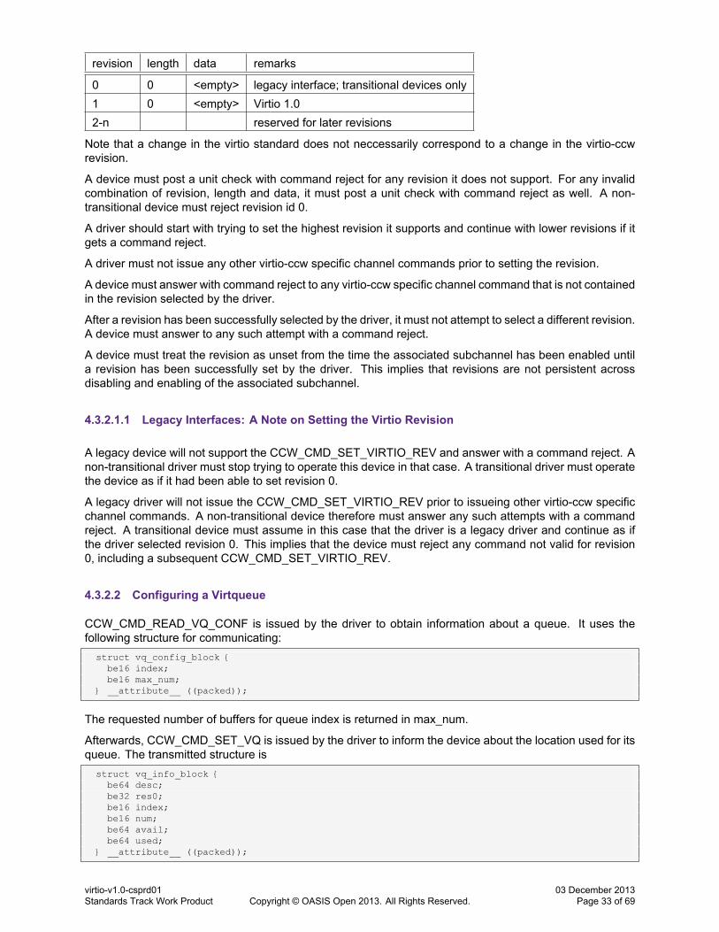
revision length data remarks
0 0 <empty> legacy interface; transitional devices only1 0 <empty> Virtio 1.02-n reserved for later revisions
Note that a change in the virtio standard does not neccessarily correspond to a change in the virtio-ccwrevision.
A device must post a unit check with command reject for any revision it does not support. For any invalidcombination of revision, length and data, it must post a unit check with command reject as well. A non-transitional device must reject revision id 0.
A driver should start with trying to set the highest revision it supports and continue with lower revisions if itgets a command reject.
A driver must not issue any other virtio-ccw specific channel commands prior to setting the revision.
A device must answer with command reject to any virtio-ccw specific channel command that is not containedin the revision selected by the driver.
After a revision has been successfully selected by the driver, it must not attempt to select a different revision.A device must answer to any such attempt with a command reject.
A device must treat the revision as unset from the time the associated subchannel has been enabled untila revision has been successfully set by the driver. This implies that revisions are not persistent acrossdisabling and enabling of the associated subchannel.
4.3.2.1.1 Legacy Interfaces: A Note on Setting the Virtio Revision
A legacy device will not support the CCW_CMD_SET_VIRTIO_REV and answer with a command reject. Anon-transitional driver must stop trying to operate this device in that case. A transitional driver must operatethe device as if it had been able to set revision 0.
A legacy driver will not issue the CCW_CMD_SET_VIRTIO_REV prior to issueing other virtio-ccw specificchannel commands. A non-transitional device therefore must answer any such attempts with a commandreject. A transitional device must assume in this case that the driver is a legacy driver and continue as ifthe driver selected revision 0. This implies that the device must reject any command not valid for revision0, including a subsequent CCW_CMD_SET_VIRTIO_REV.
4.3.2.2 Configuring a Virtqueue
CCW_CMD_READ_VQ_CONF is issued by the driver to obtain information about a queue. It uses thefollowing structure for communicating:struct vq_config_block {
be16 index;be16 max_num;
} __attribute__ ((packed));
The requested number of buffers for queue index is returned in max_num.
Afterwards, CCW_CMD_SET_VQ is issued by the driver to inform the device about the location used for itsqueue. The transmitted structure isstruct vq_info_block {
be64 desc;be32 res0;be16 index;be16 num;be64 avail;be64 used;
} __attribute__ ((packed));
virtio-v1.0-csprd01Standards Track Work Product Copyright © OASIS Open 2013. All Rights Reserved.
03 December 2013Page 33 of 69
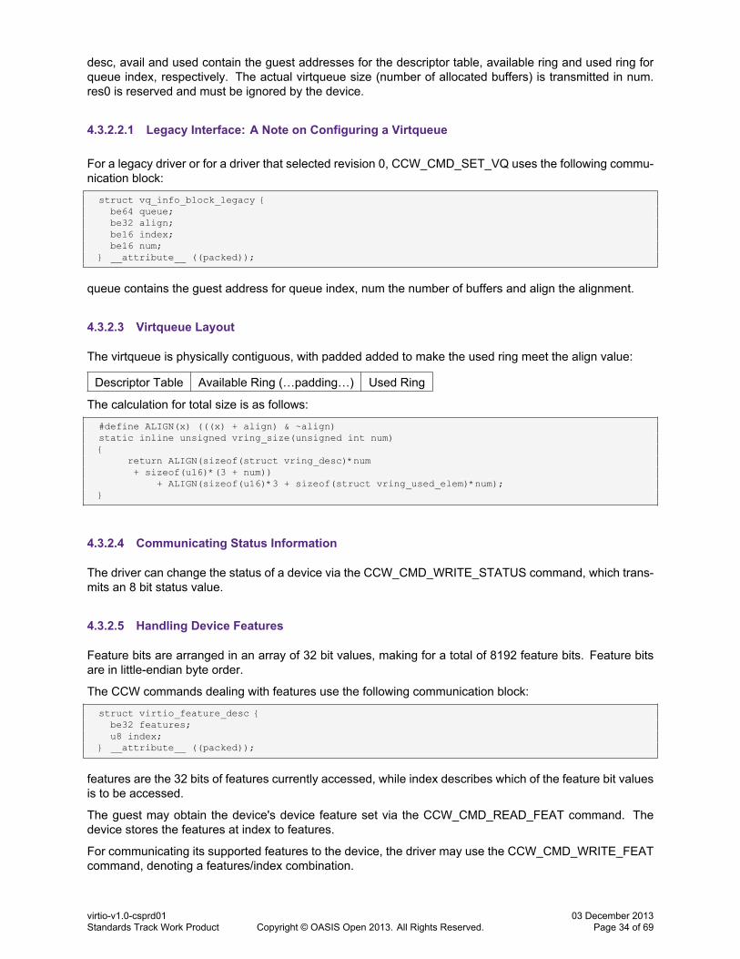
desc, avail and used contain the guest addresses for the descriptor table, available ring and used ring forqueue index, respectively. The actual virtqueue size (number of allocated buffers) is transmitted in num.res0 is reserved and must be ignored by the device.
4.3.2.2.1 Legacy Interface: A Note on Configuring a Virtqueue
For a legacy driver or for a driver that selected revision 0, CCW_CMD_SET_VQ uses the following commu-nication block:
struct vq_info_block_legacy {be64 queue;be32 align;be16 index;be16 num;
} __attribute__ ((packed));
queue contains the guest address for queue index, num the number of buffers and align the alignment.
4.3.2.3 Virtqueue Layout
The virtqueue is physically contiguous, with padded added to make the used ring meet the align value:
Descriptor Table Available Ring (…padding…) Used Ring
The calculation for total size is as follows:
#define ALIGN(x) (((x) + align) & ~align)static inline unsigned vring_size(unsigned int num){
return ALIGN(sizeof(struct vring_desc)*num+ sizeof(u16)*(3 + num))
+ ALIGN(sizeof(u16)*3 + sizeof(struct vring_used_elem)*num);}
4.3.2.4 Communicating Status Information
The driver can change the status of a device via the CCW_CMD_WRITE_STATUS command, which trans-mits an 8 bit status value.
4.3.2.5 Handling Device Features
Feature bits are arranged in an array of 32 bit values, making for a total of 8192 feature bits. Feature bitsare in little-endian byte order.
The CCW commands dealing with features use the following communication block:
struct virtio_feature_desc {be32 features;u8 index;
} __attribute__ ((packed));
features are the 32 bits of features currently accessed, while index describes which of the feature bit valuesis to be accessed.
The guest may obtain the device's device feature set via the CCW_CMD_READ_FEAT command. Thedevice stores the features at index to features.
For communicating its supported features to the device, the driver may use the CCW_CMD_WRITE_FEATcommand, denoting a features/index combination.
virtio-v1.0-csprd01Standards Track Work Product Copyright © OASIS Open 2013. All Rights Reserved.
03 December 2013Page 34 of 69
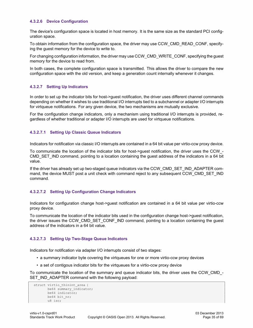
4.3.2.6 Device Configuration
The device's configuration space is located in host memory. It is the same size as the standard PCI config-uration space.
To obtain information from the configuration space, the driver may use CCW_CMD_READ_CONF, specify-ing the guest memory for the device to write to.
For changing configuration information, the driver may use CCW_CMD_WRITE_CONF, specifying the guestmemory for the device to read from.
In both cases, the complete configuration space is transmitted. This allows the driver to compare the newconfiguration space with the old version, and keep a generation count internally whenever it changes.
4.3.2.7 Setting Up Indicators
In order to set up the indicator bits for host->guest notification, the driver uses different channel commandsdepending on whether it wishes to use traditional I/O interrupts tied to a subchannel or adapter I/O interruptsfor virtqueue notifications. For any given device, the two mechanisms are mutually exclusive.
For the configuration change indicators, only a mechanism using traditional I/O interrupts is provided, re-gardless of whether traditional or adapter I/O interrupts are used for virtqueue notifications.
4.3.2.7.1 Setting Up Classic Queue Indicators
Indicators for notification via classic I/O interrupts are contained in a 64 bit value per virtio-ccw proxy device.
To communicate the location of the indicator bits for host->guest notification, the driver uses the CCW_-CMD_SET_IND command, pointing to a location containing the guest address of the indicators in a 64 bitvalue.
If the driver has already set up two-staged queue indicators via the CCW_CMD_SET_IND_ADAPTER com-mand, the device MUST post a unit check with command reject to any subsequent CCW_CMD_SET_INDcommand.
4.3.2.7.2 Setting Up Configuration Change Indicators
Indicators for configuration change host->guest notification are contained in a 64 bit value per virtio-ccwproxy device.
To communicate the location of the indicator bits used in the configuration change host->guest notification,the driver issues the CCW_CMD_SET_CONF_IND command, pointing to a location containing the guestaddress of the indicators in a 64 bit value.
4.3.2.7.3 Setting Up Two-Stage Queue Indicators
Indicators for notification via adapter I/O interrupts consist of two stages:
• a summary indicator byte covering the virtqueues for one or more virtio-ccw proxy devices
• a set of contigous indicator bits for the virtqueues for a virtio-ccw proxy device
To communicate the location of the summary and queue indicator bits, the driver uses the CCW_CMD_-SET_IND_ADAPTER command with the following payload:
struct virtio_thinint_area {be64 summary_indicator;be64 indicator;be64 bit_nr;u8 isc;
virtio-v1.0-csprd01Standards Track Work Product Copyright © OASIS Open 2013. All Rights Reserved.
03 December 2013Page 35 of 69

} __attribute__ ((packed));
summary_indicator contains the guest address of the 8 bit summary indicator. indicator contains the guestaddress of an area wherin the indicators for the devices are contained, starting at bit_nr, one bit per virtqueueof the device. Bit numbers start at the left. isc contains the I/O interruption subclass to be used for the adapterI/O interrupt. It may be different from the isc used by the proxy virtio-ccw device's subchannel.
If the driver has already set up classic queue indicators via the CCW_CMD_SET_IND command, the de-vice MUST post a unit check with command reject to any subsequent CCW_CMD_SET_IND_ADAPTERcommand.
4.3.2.7.4 Legacy Interfaces: A Note on Setting Up Indicators
Legacy devices will only support classic queue indicators; they will reject CCW_CMD_SET_IND_ADAPTERas they don't know that command.
4.3.3 Device Operation
4.3.3.1 Host->Guest Notification
There are two modes of operation regarding host->guest notifcation, classic I/O interrupts and adapter I/Ointerrupts. The mode to be used is determined by the driver by using CCW_CMD_SET_IND respectivelyCCW_CMD_SET_IND_ADAPTER to set up queue indicators.
For configuration changes, the driver will always use classic I/O interrupts.
4.3.3.1.1 Notification via Classic I/O Interrupts
If the driver used the CCW_CMD_SET_IND command to set up queue indicators, the device will use classicI/O interrupts for host->guest notification about virtqueue activity.
For notifying the driver of virtqueue buffers, the device sets the corresponding bit in the guest-providedindicators. If an interrupt is not already pending for the subchannel, the device generates an unsolicited I/Ointerrupt.
If the device wants to notify the driver about configuration changes, it sets bit 0 in the configuration indicatorsand generates an unsolicited I/O interrupt, if needed. This also applies if adapter I/O interrupts are used forqueue notifications.
4.3.3.1.2 Notification via Adapter I/O Interrupts
If the driver used the CCW_CMD_SET_IND_ADAPTER command to set up queue indicators, the devicewill use adapter I/O interrupts for host->guest notification about virtqueue activity.
For notifying the driver of virtqueue buffers, the device sets the bit in the guest-provided indicator area atthe corresponding offset. The guest-provided summary indicator is also set. An adapter I/O interrupt forthe corresponding interruption subclass is generated. The device SHOULD only generate an adapter I/Ointerrupt if the summary indicator had not been set prior to notification. The driver MUST clear the summaryindicator after receiving an adapter I/O interrupt before it processes the queue indicators.
4.3.3.1.3 Legacy Interfaces: A Note on Host->Guest Notification
As legacy devices and drivers support only classic queue indicators, host->guest notification will always bedone via classic I/O interrupts.
virtio-v1.0-csprd01Standards Track Work Product Copyright © OASIS Open 2013. All Rights Reserved.
03 December 2013Page 36 of 69

4.3.3.2 Guest->Host Notification
For notifying the device of virtqueue buffers, the driver unfortunately can't use a channel command (theasynchronous characteristics of channel I/O interact badly with the host block I/O backend). Instead, it usesa diagnose 0x500 call with subcode 3 specifying the queue, as follows:
GPR Input Value Output Value
1 0x32 Subchannel ID Host Cookie3 Virtqueue number4 Host Cookie
Host cookie is an optional per-virtqueue 64 bit value that can be used by the hypervisor to speed up thenotification execution. For each notification, the output value is returned in GPR2 and should be passed inGPR4 for the next notification:
info->cookie = do_notify(schid,virtqueue_get_queue_index(vq),info->cookie);
4.3.3.3 Early printk for Virtio Consoles
For the early printk mechanism, diagnose 0x500 with subcode 0 is used.
4.3.3.4 Resetting Devices
In order to reset a device, a driver may send the CCW_CMD_VDEV_RESET command.
virtio-v1.0-csprd01Standards Track Work Product Copyright © OASIS Open 2013. All Rights Reserved.
03 December 2013Page 37 of 69
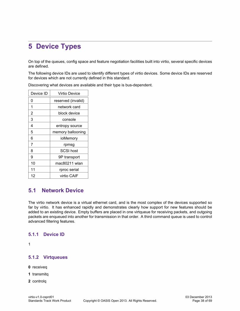
5 Device Types
On top of the queues, config space and feature negotiation facilities built into virtio, several specific devicesare defined.
The following device IDs are used to identify different types of virtio devices. Some device IDs are reservedfor devices which are not currently defined in this standard.
Discovering what devices are available and their type is bus-dependent.
Device ID Virtio Device
0 reserved (invalid)1 network card2 block device3 console4 entropy source5 memory ballooning6 ioMemory7 rpmsg8 SCSI host9 9P transport10 mac80211 wlan11 rproc serial12 virtio CAIF
5.1 Network Device
The virtio network device is a virtual ethernet card, and is the most complex of the devices supported sofar by virtio. It has enhanced rapidly and demonstrates clearly how support for new features should beadded to an existing device. Empty buffers are placed in one virtqueue for receiving packets, and outgoingpackets are enqueued into another for transmission in that order. A third command queue is used to controladvanced filtering features.
5.1.1 Device ID
1
5.1.2 Virtqueues
0 receiveq
1 transmitq
2 controlq
virtio-v1.0-csprd01Standards Track Work Product Copyright © OASIS Open 2013. All Rights Reserved.
03 December 2013Page 38 of 69

Virtqueue 2 only exists if VIRTIO_NET_F_CTRL_VQ set.
5.1.3 Feature bits
VIRTIO_NET_F_CSUM (0) Device handles packets with partial checksum
VIRTIO_NET_F_GUEST_CSUM (1) Driver handles packets with partial checksum
VIRTIO_NET_F_CTRL_GUEST_OFFLOADS (2) Control channel offloads reconfiguration support.
VIRTIO_NET_F_MAC (5) Device has given MAC address.
VIRTIO_NET_F_GUEST_TSO4 (7) Driver can receive TSOv4.
VIRTIO_NET_F_GUEST_TSO6 (8) Driver can receive TSOv6.
VIRTIO_NET_F_GUEST_ECN (9) Driver can receive TSO with ECN.
VIRTIO_NET_F_GUEST_UFO (10) Driver can receive UFO.
VIRTIO_NET_F_HOST_TSO4 (11) Device can receive TSOv4.
VIRTIO_NET_F_HOST_TSO6 (12) Device can receive TSOv6.
VIRTIO_NET_F_HOST_ECN (13) Device can receive TSO with ECN.
VIRTIO_NET_F_HOST_UFO (14) Device can receive UFO.
VIRTIO_NET_F_MRG_RXBUF (15) Driver can merge receive buffers.
VIRTIO_NET_F_STATUS (16) Configuration status field is available.
VIRTIO_NET_F_CTRL_VQ (17) Control channel is available.
VIRTIO_NET_F_CTRL_RX (18) Control channel RX mode support.
VIRTIO_NET_F_CTRL_VLAN (19) Control channel VLAN filtering.
VIRTIO_NET_F_GUEST_ANNOUNCE(21) Driver can send gratuitous packets.
5.1.3.1 Legacy Interface: Feature bits
VIRTIO_NET_F_GSO (6) Device handles packets with any GSO type.
This was supposed to indicate segmentation offload support, but upon further investigation it became clearthat multiple bits were required.
5.1.4 Device configuration layout
Two configuration fields are currently defined. The mac address field always exists (though is only validif VIRTIO_NET_F_MAC is set), and the status field only exists if VIRTIO_NET_F_STATUS is set. Tworead-only bits are currently defined for the status field: VIRTIO_NET_S_LINK_UP and VIRTIO_NET_S_-ANNOUNCE.
#define VIRTIO_NET_S_LINK_UP 1#define VIRTIO_NET_S_ANNOUNCE 2
struct virtio_net_config {u8 mac[6];le16 status;
};
virtio-v1.0-csprd01Standards Track Work Product Copyright © OASIS Open 2013. All Rights Reserved.
03 December 2013Page 39 of 69

5.1.4.1 Legacy Interface: Device configuration layout
For legacy devices, the status field in struct virtio_net_config is the native endian of the guest rather than(necessarily) little-endian.
5.1.5 Device Initialization
1. The initialization routine should identify the receive and transmission virtqueues.
2. If the VIRTIO_NET_F_MAC feature bit is set, the configuration space “mac” entry indicates the “physi-cal” address of the the network card, otherwise a private MAC address should be assigned. All driversare expected to negotiate this feature if it is set.
3. If the VIRTIO_NET_F_CTRL_VQ feature bit is negotiated, identify the control virtqueue.
4. If the VIRTIO_NET_F_STATUS feature bit is negotiated, the link status can be read from the bottombit of the “status” config field. Otherwise, the link should be assumed active.
5. The receive virtqueue should be filled with receive buffers. This is described in detail below in “SettingUp Receive Buffers”.
6. A driver can indicate that it will generate checksumless packets by negotating the VIRTIO_NET_F_-CSUM feature. This “checksum offload” is a common feature on modern network cards.
7. If that feature is negotiated1, a driver can use TCP or UDP segmentation offload by negotiating theVIRTIO_NET_F_HOST_TSO4 (IPv4 TCP), VIRTIO_NET_F_HOST_TSO6 (IPv6 TCP) and VIRTIO_-NET_F_HOST_UFO (UDP fragmentation) features. It should not send TCP packets requiring seg-mentation offload which have the Explicit Congestion Notification bit set, unless the VIRTIO_NET_F_-HOST_ECN feature is negotiated.2
8. The converse features are also available: a driver can save the virtual device some work by nego-tiating these features.3 The VIRTIO_NET_F_GUEST_CSUM feature indicates that partially check-summed packets can be received, and if it can do that then the VIRTIO_NET_F_GUEST_TSO4, VIR-TIO_NET_F_GUEST_TSO6, VIRTIO_NET_F_GUEST_UFO and VIRTIO_NET_F_GUEST_ECN arethe input equivalents of the features described above. See 5.1.6.3 Setting Up Receive Buffers and5.1.6.3 Setting Up Receive Buffers below.
5.1.6 Device Operation
Packets are transmitted by placing them in the transmitq, and buffers for incoming packets are placed in thereceiveq. In each case, the packet itself is preceeded by a header:struct virtio_net_hdr {#define VIRTIO_NET_HDR_F_NEEDS_CSUM 1
u8 flags;#define VIRTIO_NET_HDR_GSO_NONE 0#define VIRTIO_NET_HDR_GSO_TCPV4 1#define VIRTIO_NET_HDR_GSO_UDP 3#define VIRTIO_NET_HDR_GSO_TCPV6 4#define VIRTIO_NET_HDR_GSO_ECN 0x80
u8 gso_type;le16 hdr_len;le16 gso_size;le16 csum_start;le16 csum_offset;
/* Only if VIRTIO_NET_F_MRG_RXBUF: */le16 num_buffers;
1ie. VIRTIO_NET_F_HOST_TSO* and VIRTIO_NET_F_HOST_UFO are dependent on VIRTIO_NET_F_CSUM; a dvice whichoffers the offload features must offer the checksum feature, and a driver which accepts the offload features must accept the checksumfeature. Similar logic applies to the VIRTIO_NET_F_GUEST_TSO4 features depending on VIRTIO_NET_F_GUEST_CSUM.
2This is a common restriction in real, older network cards.3For example, a network packet transported between two guests on the same system may not require checksumming at all, nor
segmentation, if both guests are amenable.
virtio-v1.0-csprd01Standards Track Work Product Copyright © OASIS Open 2013. All Rights Reserved.
03 December 2013Page 40 of 69
};
The controlq is used to control device features such as filtering.
5.1.6.1 Legacy Interface: Device Operation
For legacy devices, the fields in struct virtio_net_hdr are the native endian of the guest rather than (neces-sarily) little-endian.
5.1.6.2 Packet Transmission
Transmitting a single packet is simple, but varies depending on the different features the driver negotiated.
1. If the driver negotiated VIRTIO_NET_F_CSUM, and the packet has not been fully checksummed, thenthe virtio_net_hdr's fields are set as follows. Otherwise, the packet must be fully checksummed, andflags is zero.
• flags has the VIRTIO_NET_HDR_F_NEEDS_CSUM set,
• csum_start is set to the offset within the packet to begin checksumming, and
• csum_offset indicates how many bytes after the csum_start the new (16 bit ones' complement)checksum should be placed.
For example, consider a partially checksummed TCP (IPv4) packet. It will have a 14 byte ethernetheader and 20 byte IP header followed by the TCP header (with the TCP checksum field 16 bytes intothat header). csum_start will be 14+20 = 34 (the TCP checksum includes the header), and csum_-offset will be 16. The value in the TCP checksum field should be initialized to the sum of the TCPpseudo header, so that replacing it by the ones' complement checksum of the TCP header and bodywill give the correct result.
2. If the driver negotiated VIRTIO_NET_F_HOST_TSO4, TSO6 or UFO, and the packet requires TCPsegmentation or UDP fragmentation, then the “gso_type” field is set to VIRTIO_NET_HDR_GSO_-TCPV4, TCPV6 or UDP. (Otherwise, it is set to VIRTIO_NET_HDR_GSO_NONE). In this case, pack-ets larger than 1514 bytes can be transmitted: the metadata indicates how to replicate the packetheader to cut it into smaller packets. The other gso fields are set:
• hdr_len is a hint to the device as to how much of the header needs to be kept to copy into eachpacket, usually set to the length of the headers, including the transport header.4
• gso_size is the maximum size of each packet beyond that header (ie. MSS).
• If the driver negotiated the VIRTIO_NET_F_HOST_ECN feature, the VIRTIO_NET_HDR_GSO_-ECN bit may be set in “gso_type” as well, indicating that the TCP packet has the ECN bit set.5
3. If the driver negotiated the VIRTIO_NET_F_MRG_RXBUF feature, the num_buffers field is set to zero.
4. The header and packet are added as one output buffer to the transmitq, and the device is notified ofthe new entry (see 5.1.5 Device Initialization).6
5.1.6.2.1 Packet Transmission Interrupt
Often a driver will suppress transmission interrupts using the VRING_AVAIL_F_NO_INTERRUPT flag (see5.2 Block Device) and check for used packets in the transmit path of following packets.
The normal behavior in this interrupt handler is to retrieve and new descriptors from the used ring and freethe corresponding headers and packets.
4Due to various bugs in implementations, this field is not useful as a guarantee of the transport header size.5This case is not handled by some older hardware, so is called out specifically in the protocol.6Note that the header will be two bytes longer for the VIRTIO_NET_F_MRG_RXBUF case.
virtio-v1.0-csprd01Standards Track Work Product Copyright © OASIS Open 2013. All Rights Reserved.
03 December 2013Page 41 of 69
5.1.6.3 Setting Up Receive Buffers
It is generally a good idea to keep the receive virtqueue as fully populated as possible: if it runs out, networkperformance will suffer.
If the VIRTIO_NET_F_GUEST_TSO4, VIRTIO_NET_F_GUEST_TSO6 or VIRTIO_NET_F_GUEST_UFOfeatures are used, the Driver will need to accept packets of up to 65550 bytes long (the maximum size of aTCP or UDP packet, plus the 14 byte ethernet header), otherwise 1514. bytes. So unless VIRTIO_NET_-F_MRG_RXBUF is negotiated, every buffer in the receive queue needs to be at least this length.7
If VIRTIO_NET_F_MRG_RXBUF is negotiated, each buffer must be at least the size of the struct virtio_-net_hdr.
5.1.6.3.1 Packet Receive Interrupt
When a packet is copied into a buffer in the receiveq, the optimal path is to disable further interrupts forthe receiveq (see 3.2.2 Receiving Used Buffers From The Device) and process packets until no more arefound, then re-enable them.
Processing packet involves:
1. If the driver negotiated the VIRTIO_NET_F_MRG_RXBUF feature, then the “num_buffers” field indi-cates how many descriptors this packet is spread over (including this one). This allows receipt of largepackets without having to allocate large buffers. In this case, there will be at least “num_buffers” inthe used ring, and they should be chained together to form a single packet. The other buffers will notbegin with a struct virtio_net_hdr.
2. If the VIRTIO_NET_F_MRG_RXBUF feature was not negotiated, or the “num_buffers” field is one,then the entire packet will be contained within this buffer, immediately following the struct virtio_net_-hdr.
3. If the VIRTIO_NET_F_GUEST_CSUM feature was negotiated, the VIRTIO_NET_HDR_F_NEEDS_-CSUM bit in the “flags” field may be set: if so, the checksum on the packet is incomplete and the “csum_start” and “csum_offset” fields indicate how to calculate it (see Packet Transmission point 1).
4. If the VIRTIO_NET_F_GUEST_TSO4, TSO6 or UFO options were negotiated, then the “gso_type”may be something other than VIRTIO_NET_HDR_GSO_NONE, and the “gso_size” field indicates thedesired MSS (see Packet Transmission point 2).
5.1.6.4 Control Virtqueue
The driver uses the control virtqueue (if VIRTIO_NET_F_VTRL_VQ is negotiated) to send commands tomanipulate various features of the device which would not easily map into the configuration space.
All commands are of the following form:
struct virtio_net_ctrl {u8 class;u8 command;u8 command-specific-data[];u8 ack;
};
/* ack values */#define VIRTIO_NET_OK 0#define VIRTIO_NET_ERR 1
The class, command and command-specific-data are set by the driver, and the device sets the ack byte.There is little it can do except issue a diagnostic if the ack byte is not VIRTIO_NET_OK.
7Obviously each one can be split across multiple descriptor elements.
virtio-v1.0-csprd01Standards Track Work Product Copyright © OASIS Open 2013. All Rights Reserved.
03 December 2013Page 42 of 69
5.1.6.4.1 Packet Receive Filtering
If the VIRTIO_NET_F_CTRL_RX feature is negotiated, the driver can send control commands for promis-cuous mode, multicast receiving, and filtering of MAC addresses.
Note that in general, these commands are best-effort: unwanted packets may still arrive.
5.1.6.4.2 Setting Promiscuous Mode
#define VIRTIO_NET_CTRL_RX 0#define VIRTIO_NET_CTRL_RX_PROMISC 0#define VIRTIO_NET_CTRL_RX_ALLMULTI 1
The class VIRTIO_NET_CTRL_RX has two commands: VIRTIO_NET_CTRL_RX_PROMISC turns promis-cuous mode on and off, and VIRTIO_NET_CTRL_RX_ALLMULTI turns all-multicast receive on and off. Thecommand-specific-data is one byte containing 0 (off) or 1 (on).
5.1.6.4.3 Setting MAC Address Filtering
struct virtio_net_ctrl_mac {le32 entries;u8 macs[entries][ETH_ALEN];
};
#define VIRTIO_NET_CTRL_MAC 1#define VIRTIO_NET_CTRL_MAC_TABLE_SET 0
The device can filter incoming packets by any number of destination MAC addresses.8 This table is setusing the class VIRTIO_NET_CTRL_MAC and the command VIRTIO_NET_CTRL_MAC_TABLE_SET. Thecommand-specific-data is two variable length tables of 6-byte MAC addresses. The first table containsunicast addresses, and the second contains multicast addresses.
5.1.6.4.3.1 Legacy Interface: Setting MAC Address Filtering
For legacy devices, the entries field in struct virtio_net_ctrl_mac is the native endian of the guest rather than(necessarily) little-endian.
5.1.6.4.4 VLAN Filtering
If the driver negotiates the VIRTION_NET_F_CTRL_VLAN feature, it can control a VLAN filter table in thedevice.
#define VIRTIO_NET_CTRL_VLAN 2#define VIRTIO_NET_CTRL_VLAN_ADD 0#define VIRTIO_NET_CTRL_VLAN_DEL 1
Both the VIRTIO_NET_CTRL_VLAN_ADD and VIRTIO_NET_CTRL_VLAN_DEL command take a little-endian 16-bit VLAN id as the command-specific-data.
5.1.6.4.4.1 Legacy Interface: VLAN Filtering
For legacy devices, the VLAN id is in the native endian of the guest rather than (necessarily) little-endian.8Since there are no guarentees, it can use a hash filter or silently switch to allmulti or promiscuous mode if it is given too many
addresses.
virtio-v1.0-csprd01Standards Track Work Product Copyright © OASIS Open 2013. All Rights Reserved.
03 December 2013Page 43 of 69

5.1.6.4.5 Gratuitous Packet Sending
If the driver negotiates the VIRTIO_NET_F_GUEST_ANNOUNCE (depends on VIRTIO_NET_F_CTRL_-VQ), it can ask the driver to send gratuitous packets; this is usually done after the guest has been physicallymigrated, and needs to announce its presence on the new network links. (As hypervisor does not have theknowledge of guest network configuration (eg. tagged vlan) it is simplest to prod the guest in this way).
#define VIRTIO_NET_CTRL_ANNOUNCE 3#define VIRTIO_NET_CTRL_ANNOUNCE_ACK 0
The Driver needs to check VIRTIO_NET_S_ANNOUNCE bit in status field when it notices the changes ofdevice configuration. The command VIRTIO_NET_CTRL_ANNOUNCE_ACK is used to indicate that driverhas recevied the notification and device would clear the VIRTIO_NET_S_ANNOUNCE bit in the status filedafter it received this command.
Processing this notification involves:
1. Sending the gratuitous packets or marking there are pending gratuitous packets to be sent and lettingdeferred routine to send them.
2. Sending VIRTIO_NET_CTRL_ANNOUNCE_ACK command through control vq.
5.1.6.4.6 Offloads State Configuration
If the VIRTIO_NET_F_CTRL_GUEST_OFFLOADS feature is negotiated, the driver can send control com-mands for dynamic offloads state configuration.
5.1.6.4.6.1 Setting Offloads State
le64 offloads;
#define VIRTIO_NET_F_GUEST_CSUM 1#define VIRTIO_NET_F_GUEST_TSO4 7#define VIRTIO_NET_F_GUEST_TSO6 8#define VIRTIO_NET_F_GUEST_ECN 9#define VIRTIO_NET_F_GUEST_UFO 10
#define VIRTIO_NET_CTRL_GUEST_OFFLOADS 5#define VIRTIO_NET_CTRL_GUEST_OFFLOADS_SET 0
The class VIRTIO_NET_CTRL_GUEST_OFFLOADS has one command: VIRTIO_NET_CTRL_GUEST_-OFFLOADS_SET applies the new offloads configuration.
le64 value passed as command data is a bitmask, bits set define offloads to be enabled, bits cleared -offloads to be disabled.
There is a corresponding device feature for each offload. Upon feature negotiation corresponding offloadgets enabled to preserve backward compartibility.
Corresponding feature must be negotiated at startup in order to allow dynamic change of specific offloadstate.
5.1.6.4.6.2 Legacy Interface: Setting Offloads State
For legacy devices, the offloads field is the native endian of the guest rather than (necessarily) little-endian.
virtio-v1.0-csprd01Standards Track Work Product Copyright © OASIS Open 2013. All Rights Reserved.
03 December 2013Page 44 of 69
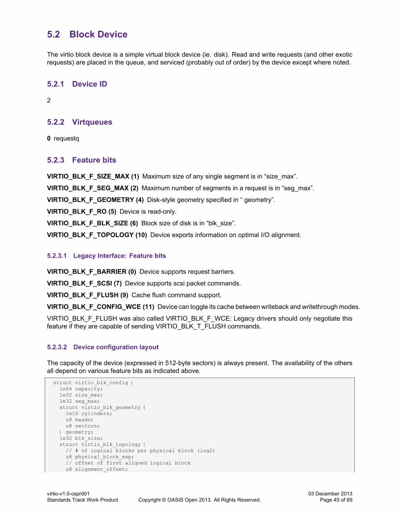
5.2 Block Device
The virtio block device is a simple virtual block device (ie. disk). Read and write requests (and other exoticrequests) are placed in the queue, and serviced (probably out of order) by the device except where noted.
5.2.1 Device ID
2
5.2.2 Virtqueues
0 requestq
5.2.3 Feature bits
VIRTIO_BLK_F_SIZE_MAX (1) Maximum size of any single segment is in “size_max”.
VIRTIO_BLK_F_SEG_MAX (2) Maximum number of segments in a request is in “seg_max”.
VIRTIO_BLK_F_GEOMETRY (4) Disk-style geometry specified in “ geometry”.
VIRTIO_BLK_F_RO (5) Device is read-only.
VIRTIO_BLK_F_BLK_SIZE (6) Block size of disk is in “blk_size”.
VIRTIO_BLK_F_TOPOLOGY (10) Device exports information on optimal I/O alignment.
5.2.3.1 Legacy Interface: Feature bits
VIRTIO_BLK_F_BARRIER (0) Device supports request barriers.
VIRTIO_BLK_F_SCSI (7) Device supports scsi packet commands.
VIRTIO_BLK_F_FLUSH (9) Cache flush command support.
VIRTIO_BLK_F_CONFIG_WCE (11) Device can toggle its cache betweenwriteback andwritethroughmodes.
VIRTIO_BLK_F_FLUSH was also called VIRTIO_BLK_F_WCE: Legacy drivers should only negotiate thisfeature if they are capable of sending VIRTIO_BLK_T_FLUSH commands.
5.2.3.2 Device configuration layout
The capacity of the device (expressed in 512-byte sectors) is always present. The availability of the othersall depend on various feature bits as indicated above.
struct virtio_blk_config {le64 capacity;le32 size_max;le32 seg_max;struct virtio_blk_geometry {le16 cylinders;u8 heads;u8 sectors;
} geometry;le32 blk_size;struct virtio_blk_topology {// # of logical blocks per physical block (log2)u8 physical_block_exp;// offset of first aligned logical blocku8 alignment_offset;
virtio-v1.0-csprd01Standards Track Work Product Copyright © OASIS Open 2013. All Rights Reserved.
03 December 2013Page 45 of 69

// suggested minimum I/O size in blocksle16 min_io_size;// optimal (suggested maximum) I/O size in blocksle32 opt_io_size;
} topology;u8 reserved;
};
5.2.3.2.1 Legacy Interface: Device configuration layout
For legacy devices, the fields in struct virtio_blk_config are the native endian of the guest rather than (nec-essarily) little-endian.
5.2.4 Device Initialization
1. The device size should be read from the “capacity” configuration field. No requests should be submittedwhich goes beyond this limit.
2. If the VIRTIO_BLK_F_BLK_SIZE feature is negotiated, the blk_size field can be read to determine theoptimal sector size for the driver to use. This does not affect the units used in the protocol (always512 bytes), but awareness of the correct value can affect performance.
3. If the VIRTIO_BLK_F_RO feature is set by the device, any write requests will fail.
4. If the VIRTIO_BLK_F_TOPOLOGY feature is negotiated, the fields in the topology struct can be readto determine the physical block size and optimal I/O lengths for the driver to use. This also does notaffect the units in the protocol, only performance.
5.2.4.1 Legacy Interface: Device Initialization
The reserved field used to be called writeback. If the VIRTIO_BLK_F_CONFIG_WCE feature is offered, thecache mode should be read from the writeback field of the configuration if available; the driver can also writeto the field in order to toggle the cache between writethrough (0) and writeback (1) mode. If the feature isnot available, the driver can instead look at the result of negotiating VIRTIO_BLK_F_FLUSH: the cache willbe in writeback mode after reset if and only if VIRTIO_BLK_F_FLUSH is negotiated.
Some older legacy devices did not operate in writethrough mode even after a driver announced lack ofsupport for VIRTIO_BLK_F_FLUSH.
5.2.5 Device Operation
The driver queues requests to the virtqueue, and they are used by the device (not necessarily in order).Each request is of form:
struct virtio_blk_req {le32 type;le32 reserved;le64 sector;char data[][512];u8 status;
};
The type of the request is either a read (VIRTIO_BLK_T_IN), a write (VIRTIO_BLK_T_OUT), or a flush(VIRTIO_BLK_T_FLUSH or VIRTIO_BLK_T_FLUSH_OUT9).
9The FLUSH and FLUSH_OUT types are equivalent, the device does not distinguish between them
virtio-v1.0-csprd01Standards Track Work Product Copyright © OASIS Open 2013. All Rights Reserved.
03 December 2013Page 46 of 69

#define VIRTIO_BLK_T_IN 0#define VIRTIO_BLK_T_OUT 1#define VIRTIO_BLK_T_FLUSH 4#define VIRTIO_BLK_T_FLUSH_OUT 5
The sector number indicates the offset (multiplied by 512) where the read or write is to occur. This field isunused and set to 0 for scsi packet commands and for flush commands.
The final status byte is written by the device: either VIRTIO_BLK_S_OK for success, VIRTIO_BLK_S_-IOERR for device or driver error or VIRTIO_BLK_S_UNSUPP for a request unsupported by device:
#define VIRTIO_BLK_S_OK 0#define VIRTIO_BLK_S_IOERR 1#define VIRTIO_BLK_S_UNSUPP 2
Any writes completed before the submission of the flush command should be committed to non-volatilestorage by the device.
5.2.5.1 Legacy Interface: Device Operation
For legacy devices, the fields in struct virtio_blk_req are the native endian of the guest rather than (neces-sarily) little-endian.
The 'reserved' field was previously called ioprio. The ioprio field is a hint about the relative priorities ofrequests to the device: higher numbers indicate more important requests.
#define VIRTIO_BLK_T_BARRIER 0x80000000
If the device has VIRTIO_BLK_F_BARRIER feature the high bit (VIRTIO_BLK_T_BARRIER) indicates thatthis request acts as a barrier and that all preceeding requests must be complete before this one, and allfollowing requests must not be started until this is complete. Note that a barrier does not flush caches in theunderlying backend device in host, and thus does not serve as data consistency guarantee. Driver mustuse FLUSH request to flush the host cache.
If the device has VIRTIO_BLK_F_SCSI feature, it can also support scsi packet command requests, each ofthese requests is of form:
/* All fields are in guest's native endian. */struct virtio_scsi_pc_req {
u32 type;u32 ioprio;u64 sector;char cmd[];char data[][512];
#define SCSI_SENSE_BUFFERSIZE 96u8 sense[SCSI_SENSE_BUFFERSIZE];u32 errors;u32 data_len;u32 sense_len;u32 residual;u8 status;
};
A request type can also be a scsi packet command (VIRTIO_BLK_T_SCSI_CMDor VIRTIO_BLK_T_SCSI_-CMD_OUT). The two types are equivalent, the device does not distinguish between them:
#define VIRTIO_BLK_T_SCSI_CMD 2#define VIRTIO_BLK_T_SCSI_CMD_OUT 3
The cmd field is only present for scsi packet command requests, and indicates the command to perform.This field must reside in a single, separate read-only buffer; command length can be derived from the lengthof this buffer.
virtio-v1.0-csprd01Standards Track Work Product Copyright © OASIS Open 2013. All Rights Reserved.
03 December 2013Page 47 of 69
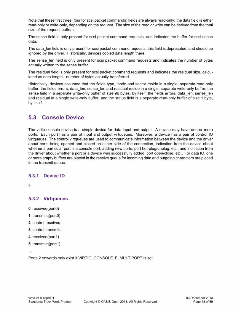
Note that these first three (four for scsi packet commands) fields are always read-only: the data field is eitherread-only or write-only, depending on the request. The size of the read or write can be derived from the totalsize of the request buffers.
The sense field is only present for scsi packet command requests, and indicates the buffer for scsi sensedata.
The data_len field is only present for scsi packet command requests, this field is deprecated, and should beignored by the driver. Historically, devices copied data length there.
The sense_len field is only present for scsi packet command requests and indicates the number of bytesactually written to the sense buffer.
The residual field is only present for scsi packet command requests and indicates the residual size, calcu-lated as data length - number of bytes actually transferred.
Historically, devices assumed that the fields type, ioprio and sector reside in a single, separate read-onlybuffer; the fields errors, data_len, sense_len and residual reside in a single, separate write-only buffer; thesense field in a separate write-only buffer of size 96 bytes, by itself; the fields errors, data_len, sense_lenand residual in a single write-only buffer; and the status field is a separate read-only buffer of size 1 byte,by itself.
5.3 Console Device
The virtio console device is a simple device for data input and output. A device may have one or moreports. Each port has a pair of input and output virtqueues. Moreover, a device has a pair of control IOvirtqueues. The control virtqueues are used to communicate information between the device and the driverabout ports being opened and closed on either side of the connection, indication from the device aboutwhether a particular port is a console port, adding new ports, port hot-plug/unplug, etc., and indication fromthe driver about whether a port or a device was successfully added, port open/close, etc.. For data IO, oneor more empty buffers are placed in the receive queue for incoming data and outgoing characters are placedin the transmit queue.
5.3.1 Device ID
3
5.3.2 Virtqueues
0 receiveq(port0)
1 transmitq(port0)
2 control receiveq
3 control transmitq
4 receiveq(port1)
5 transmitq(port1)
…
Ports 2 onwards only exist if VIRTIO_CONSOLE_F_MULTIPORT is set.
virtio-v1.0-csprd01Standards Track Work Product Copyright © OASIS Open 2013. All Rights Reserved.
03 December 2013Page 48 of 69

5.3.3 Feature bits
VIRTIO_CONSOLE_F_SIZE (0) Configuration cols and rows fields are valid.
VIRTIO_CONSOLE_F_MULTIPORT(1) Device has support for multiple ports; configuration fields nr_portsand max_nr_ports are valid and control virtqueues will be used.
5.3.4 Device configuration layout
The size of the console is supplied in the configuration space if the VIRTIO_CONSOLE_F_SIZE feature isset. Furthermore, if the VIRTIO_CONSOLE_F_MULTIPORT feature is set, the maximum number of portssupported by the device can be fetched.
struct virtio_console_config {le16 cols;le16 rows;le32 max_nr_ports;
};
5.3.4.1 Legacy Interface: Device configuration layout
For legacy devices, the fields in struct virtio_console_config are the native endian of the guest rather than(necessarily) little-endian.
5.3.5 Device Initialization
1. If the VIRTIO_CONSOLE_F_SIZE feature is negotiated, the driver can read the console dimensionsfrom the configuration fields.
2. If the VIRTIO_CONSOLE_F_MULTIPORT feature is negotiated, the driver can spawn multiple ports,not all of which may be attached to a console. Some could be generic ports. In this case, the controlvirtqueues are enabled and according to the max_nr_ports configuration-space value, the appropriatenumber of virtqueues are created. A control message indicating the driver is ready is sent to the device.The device can then send control messages for adding new ports to the device. After creating andinitializing each port, a VIRTIO_CONSOLE_PORT_READY control message is sent to the device forthat port so the device can let us know of any additional configuration options set for that port.
3. The receiveq for each port is populated with one or more receive buffers.
5.3.6 Device Operation
1. For output, a buffer containing the characters is placed in the port's transmitq.10
2. When a buffer is used in the receiveq (signalled by an interrupt), the contents is the input to the portassociated with the virtqueue for which the notification was received.
3. If the driver negotiated the VIRTIO_CONSOLE_F_SIZE feature, a configuration change interrupt mayoccur. The updated size can be read from the configuration fields.
4. If the driver negotiated the VIRTIO_CONSOLE_F_MULTIPORT feature, active ports are announcedby the device using the VIRTIO_CONSOLE_PORT_ADD control message. The same message isused for port hot-plug as well.
10Because this is high importance and low bandwidth, the current Linux implementation polls for the buffer to be used, rather thanwaiting for an interrupt, simplifying the implementation significantly. However, for generic serial ports with the O_NONBLOCK flagset, the polling limitation is relaxed and the consumed buffers are freed upon the next write or poll call or when a port is closed orhot-unplugged.
virtio-v1.0-csprd01Standards Track Work Product Copyright © OASIS Open 2013. All Rights Reserved.
03 December 2013Page 49 of 69

5. If the device specified a port `name', a sysfs attribute is created with the name filled in, so that udevrules can be written that can create a symlink from the port's name to the char device for port discoveryby applications in the driver.
6. Changes to ports' state are effected by control messages. Appropriate action is taken on the portindicated in the control message. The layout of the structure of the control buffer and the eventsassociated are:
struct virtio_console_control {le32 id; /* Port number */le16 event; /* The kind of control event */le16 value; /* Extra information for the event */
};
/* Some events for the internal messages (control packets) */#define VIRTIO_CONSOLE_DEVICE_READY 0#define VIRTIO_CONSOLE_PORT_ADD 1#define VIRTIO_CONSOLE_PORT_REMOVE 2#define VIRTIO_CONSOLE_PORT_READY 3#define VIRTIO_CONSOLE_CONSOLE_PORT 4#define VIRTIO_CONSOLE_RESIZE 5#define VIRTIO_CONSOLE_PORT_OPEN 6#define VIRTIO_CONSOLE_PORT_NAME 7
5.3.6.1 Legacy Interface: Device Operation
For legacy devices, the fields in struct virtio_console_control are the native endian of the guest rather than(necessarily) little-endian.
5.4 Entropy Device
The virtio entropy device supplies high-quality randomness for guest use.
5.4.1 Device ID
4
5.4.2 Virtqueues
0 requestq
5.4.3 Feature bits
None currently defined
5.4.4 Device configuration layout
None currently defined.
5.4.5 Device Initialization
1. The virtqueue is initialized
virtio-v1.0-csprd01Standards Track Work Product Copyright © OASIS Open 2013. All Rights Reserved.
03 December 2013Page 50 of 69

5.4.6 Device Operation
When the driver requires random bytes, it places the descriptor of one or more buffers in the queue. It willbe completely filled by random data by the device.
5.5 Memory Balloon Device
The virtio memory balloon device is a primitive device for managing guest memory: the device asks for acertain amount of memory, and the driver supplies it (or withdraws it, if the device has more than it asksfor). This allows the guest to adapt to changes in allowance of underlying physical memory. If the featureis negotiated, the device can also be used to communicate guest memory statistics to the host.
5.5.1 Device ID
5
5.5.2 Virtqueues
0 inflateq
1 deflateq
2 statsq.
Virtqueue 2 only exists if VIRTIO_BALLON_F_STATS_VQ set.
5.5.3 Feature bits
VIRTIO_BALLOON_F_MUST_TELL_HOST (0) Host must be told before pages from the balloon are used.
VIRTIO_BALLOON_F_STATS_VQ (1) A virtqueue for reporting guest memory statistics is present.
5.5.4 Device configuration layout
Both fields of this configuration are always available.
struct virtio_balloon_config {le32 num_pages;le32 actual;
};
5.5.4.1 Legacy Interface: Device configuration layout
Note that these fields are always little endian, despite convention that legacy device fields are guest endian.
5.5.5 Device Initialization
1. The inflate and deflate virtqueues are identified.
2. If the VIRTIO_BALLOON_F_STATS_VQ feature bit is negotiated:
(a) Identify the stats virtqueue.
(b) Add one empty buffer to the stats virtqueue and notify the device.
virtio-v1.0-csprd01Standards Track Work Product Copyright © OASIS Open 2013. All Rights Reserved.
03 December 2013Page 51 of 69
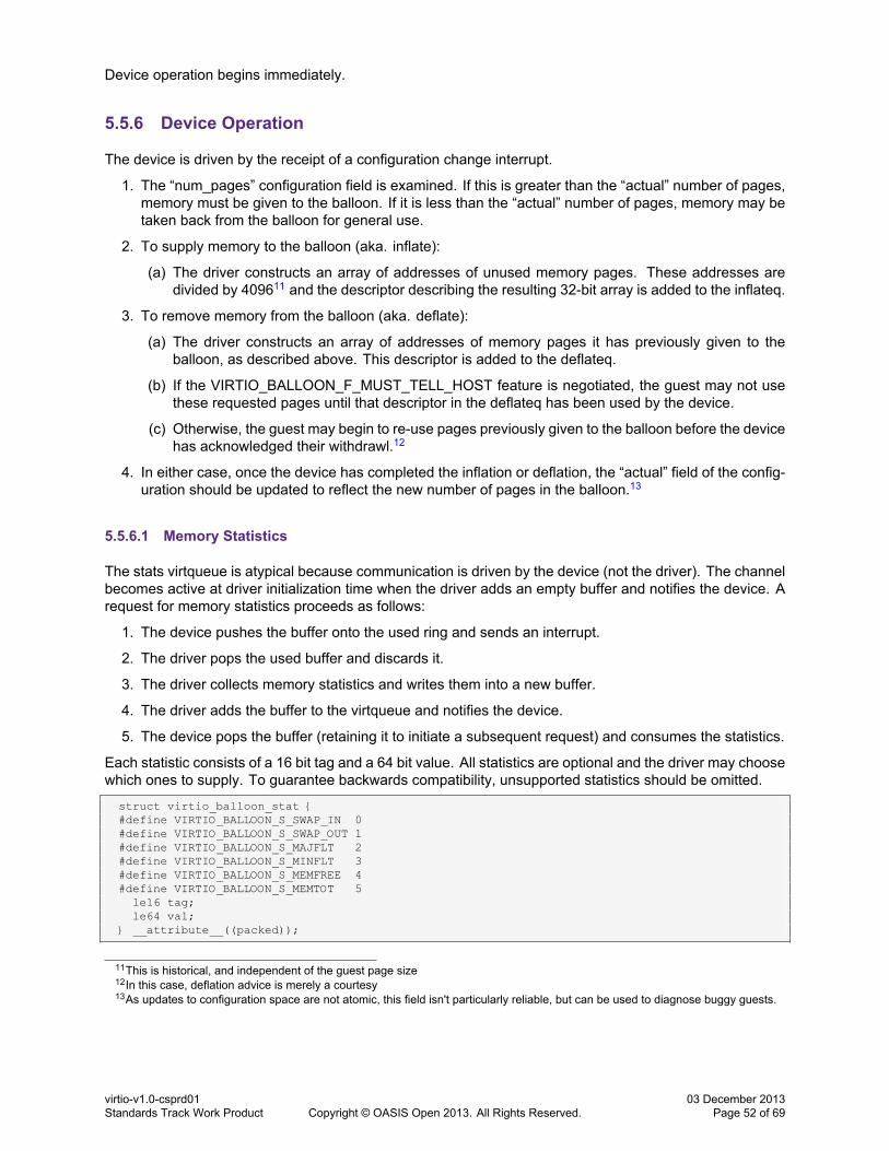
Device operation begins immediately.
5.5.6 Device Operation
The device is driven by the receipt of a configuration change interrupt.
1. The “num_pages” configuration field is examined. If this is greater than the “actual” number of pages,memory must be given to the balloon. If it is less than the “actual” number of pages, memory may betaken back from the balloon for general use.
2. To supply memory to the balloon (aka. inflate):
(a) The driver constructs an array of addresses of unused memory pages. These addresses aredivided by 409611 and the descriptor describing the resulting 32-bit array is added to the inflateq.
3. To remove memory from the balloon (aka. deflate):
(a) The driver constructs an array of addresses of memory pages it has previously given to theballoon, as described above. This descriptor is added to the deflateq.
(b) If the VIRTIO_BALLOON_F_MUST_TELL_HOST feature is negotiated, the guest may not usethese requested pages until that descriptor in the deflateq has been used by the device.
(c) Otherwise, the guest may begin to re-use pages previously given to the balloon before the devicehas acknowledged their withdrawl.12
4. In either case, once the device has completed the inflation or deflation, the “actual” field of the config-uration should be updated to reflect the new number of pages in the balloon.13
5.5.6.1 Memory Statistics
The stats virtqueue is atypical because communication is driven by the device (not the driver). The channelbecomes active at driver initialization time when the driver adds an empty buffer and notifies the device. Arequest for memory statistics proceeds as follows:
1. The device pushes the buffer onto the used ring and sends an interrupt.
2. The driver pops the used buffer and discards it.
3. The driver collects memory statistics and writes them into a new buffer.
4. The driver adds the buffer to the virtqueue and notifies the device.
5. The device pops the buffer (retaining it to initiate a subsequent request) and consumes the statistics.
Each statistic consists of a 16 bit tag and a 64 bit value. All statistics are optional and the driver may choosewhich ones to supply. To guarantee backwards compatibility, unsupported statistics should be omitted.
struct virtio_balloon_stat {#define VIRTIO_BALLOON_S_SWAP_IN 0#define VIRTIO_BALLOON_S_SWAP_OUT 1#define VIRTIO_BALLOON_S_MAJFLT 2#define VIRTIO_BALLOON_S_MINFLT 3#define VIRTIO_BALLOON_S_MEMFREE 4#define VIRTIO_BALLOON_S_MEMTOT 5
le16 tag;le64 val;
} __attribute__((packed));
11This is historical, and independent of the guest page size12In this case, deflation advice is merely a courtesy13As updates to configuration space are not atomic, this field isn't particularly reliable, but can be used to diagnose buggy guests.
virtio-v1.0-csprd01Standards Track Work Product Copyright © OASIS Open 2013. All Rights Reserved.
03 December 2013Page 52 of 69
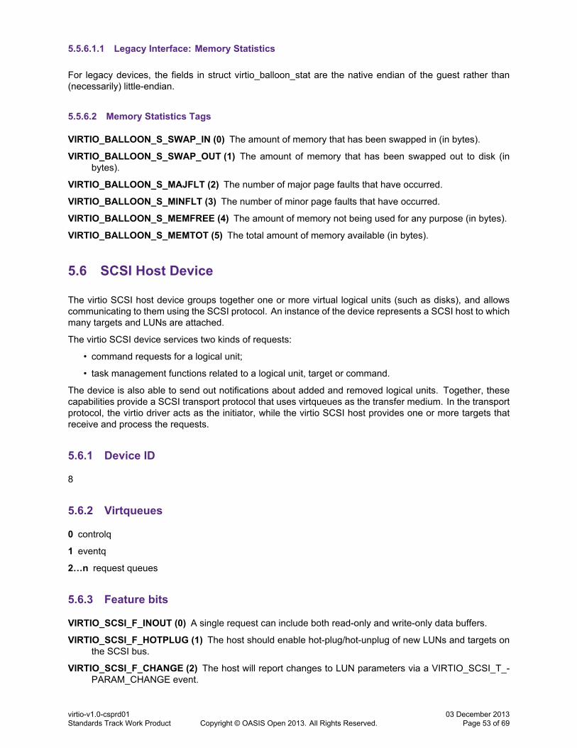
5.5.6.1.1 Legacy Interface: Memory Statistics
For legacy devices, the fields in struct virtio_balloon_stat are the native endian of the guest rather than(necessarily) little-endian.
5.5.6.2 Memory Statistics Tags
VIRTIO_BALLOON_S_SWAP_IN (0) The amount of memory that has been swapped in (in bytes).
VIRTIO_BALLOON_S_SWAP_OUT (1) The amount of memory that has been swapped out to disk (inbytes).
VIRTIO_BALLOON_S_MAJFLT (2) The number of major page faults that have occurred.
VIRTIO_BALLOON_S_MINFLT (3) The number of minor page faults that have occurred.
VIRTIO_BALLOON_S_MEMFREE (4) The amount of memory not being used for any purpose (in bytes).
VIRTIO_BALLOON_S_MEMTOT (5) The total amount of memory available (in bytes).
5.6 SCSI Host Device
The virtio SCSI host device groups together one or more virtual logical units (such as disks), and allowscommunicating to them using the SCSI protocol. An instance of the device represents a SCSI host to whichmany targets and LUNs are attached.
The virtio SCSI device services two kinds of requests:
• command requests for a logical unit;
• task management functions related to a logical unit, target or command.
The device is also able to send out notifications about added and removed logical units. Together, thesecapabilities provide a SCSI transport protocol that uses virtqueues as the transfer medium. In the transportprotocol, the virtio driver acts as the initiator, while the virtio SCSI host provides one or more targets thatreceive and process the requests.
5.6.1 Device ID
8
5.6.2 Virtqueues
0 controlq
1 eventq
2…n request queues
5.6.3 Feature bits
VIRTIO_SCSI_F_INOUT (0) A single request can include both read-only and write-only data buffers.
VIRTIO_SCSI_F_HOTPLUG (1) The host should enable hot-plug/hot-unplug of new LUNs and targets onthe SCSI bus.
VIRTIO_SCSI_F_CHANGE (2) The host will report changes to LUN parameters via a VIRTIO_SCSI_T_-PARAM_CHANGE event.
virtio-v1.0-csprd01Standards Track Work Product Copyright © OASIS Open 2013. All Rights Reserved.
03 December 2013Page 53 of 69

5.6.4 Device configuration layout
All fields of this configuration are always available. sense_size and cdb_size are writable by the driver.
struct virtio_scsi_config {le32 num_queues;le32 seg_max;le32 max_sectors;le32 cmd_per_lun;le32 event_info_size;le32 sense_size;le32 cdb_size;le16 max_channel;le16 max_target;le32 max_lun;
};
num_queues is the total number of request virtqueues exposed by the device. The driver is free to useonly one request queue, or it can use more to achieve better performance.
seg_max is the maximum number of segments that can be in a command. A bidirectional command caninclude seg_max input segments and seg_max output segments.
max_sectors is a hint to the driver about the maximum transfer size it should use.
cmd_per_lun is a hint to the driver about the maximum number of linked commands it should send to oneLUN. The actual value to be used is the minimum of cmd_per_lun and the virtqueue size.
event_info_size is the maximum size that the device will fill for buffers that the driver places in the eventq.The driver should always put buffers at least of this size. It is written by the device depending on theset of negotated features.
sense_size is the maximum size of the sense data that the device will write. The default value is writtenby the device and will always be 96, but the driver can modify it. It is restored to the default when thedevice is reset.
cdb_size is the maximum size of the CDB that the driver will write. The default value is written by the deviceand will always be 32, but the driver can likewise modify it. It is restored to the default when the deviceis reset.
max_channel, max_target and max_lun can be used by the driver as hints to constrain scanning thelogical units on the host.h
5.6.4.1 Legacy Interface: Device configuration layout
For legacy devices, the fields in struct virtio_scsi_config are the native endian of the guest rather than(necessarily) little-endian.
5.6.5 Device Initialization
The initialization routine should first of all discover the device's virtqueues.
If the driver uses the eventq, it should then place at least a buffer in the eventq.
The driver can immediately issue requests (for example, INQUIRY or REPORT LUNS) or task managementfunctions (for example, I_T RESET).
5.6.6 Device Operation
Device operation consists of operating request queues, the control queue and the event queue.
virtio-v1.0-csprd01Standards Track Work Product Copyright © OASIS Open 2013. All Rights Reserved.
03 December 2013Page 54 of 69

5.6.6.1 Device Operation: Request Queues
The driver queues requests to an arbitrary request queue, and they are used by the device on that samequeue. It is the responsibility of the driver to ensure strict request ordering for commands placed on differentqueues, because they will be consumed with no order constraints.
Requests have the following format:
struct virtio_scsi_req_cmd {// Read-onlyu8 lun[8];le64 id;u8 task_attr;u8 prio;u8 crn;char cdb[cdb_size];char dataout[];// Write-only partle32 sense_len;le32 residual;le16 status_qualifier;u8 status;u8 response;u8 sense[sense_size];char datain[];
};
/* command-specific response values */#define VIRTIO_SCSI_S_OK 0#define VIRTIO_SCSI_S_OVERRUN 1#define VIRTIO_SCSI_S_ABORTED 2#define VIRTIO_SCSI_S_BAD_TARGET 3#define VIRTIO_SCSI_S_RESET 4#define VIRTIO_SCSI_S_BUSY 5#define VIRTIO_SCSI_S_TRANSPORT_FAILURE 6#define VIRTIO_SCSI_S_TARGET_FAILURE 7#define VIRTIO_SCSI_S_NEXUS_FAILURE 8#define VIRTIO_SCSI_S_FAILURE 9
/* task_attr */#define VIRTIO_SCSI_S_SIMPLE 0#define VIRTIO_SCSI_S_ORDERED 1#define VIRTIO_SCSI_S_HEAD 2#define VIRTIO_SCSI_S_ACA 3
The lun field addresses a target and logical unit in the virtio-scsi device's SCSI domain. The only supportedformat for the LUN field is: first byte set to 1, second byte set to target, third and fourth byte representinga single level LUN structure, followed by four zero bytes. With this representation, a virtio-scsi device canserve up to 256 targets and 16384 LUNs per target.
The id field is the command identifier (“tag”).
task_attr, prio and crn should be left to zero. task_attr defines the task attribute as in the table above, butall task attributes may be mapped to SIMPLE by the device; crn may also be provided by clients, but isgenerally expected to be 0. The maximum CRN value defined by the protocol is 255, since CRN is storedin an 8-bit integer.
All of these fields are defined in SAM. They are always read-only, as are the cdb and dataout field. Thecdb_size is taken from the configuration space.
sense and subsequent fields are always write-only. The sense_len field indicates the number of bytesactually written to the sense buffer. The residual field indicates the residual size, calculated as “data_length- number_of_transferred_bytes”, for read or write operations. For bidirectional commands, the number_of_-transferred_bytes includes both read and written bytes. A residual field that is less than the size of datainmeans that the dataout field was processed entirely. A residual field that exceeds the size of datain meansthat the dataout field was processed partially and the datain field was not processed at all.
virtio-v1.0-csprd01Standards Track Work Product Copyright © OASIS Open 2013. All Rights Reserved.
03 December 2013Page 55 of 69
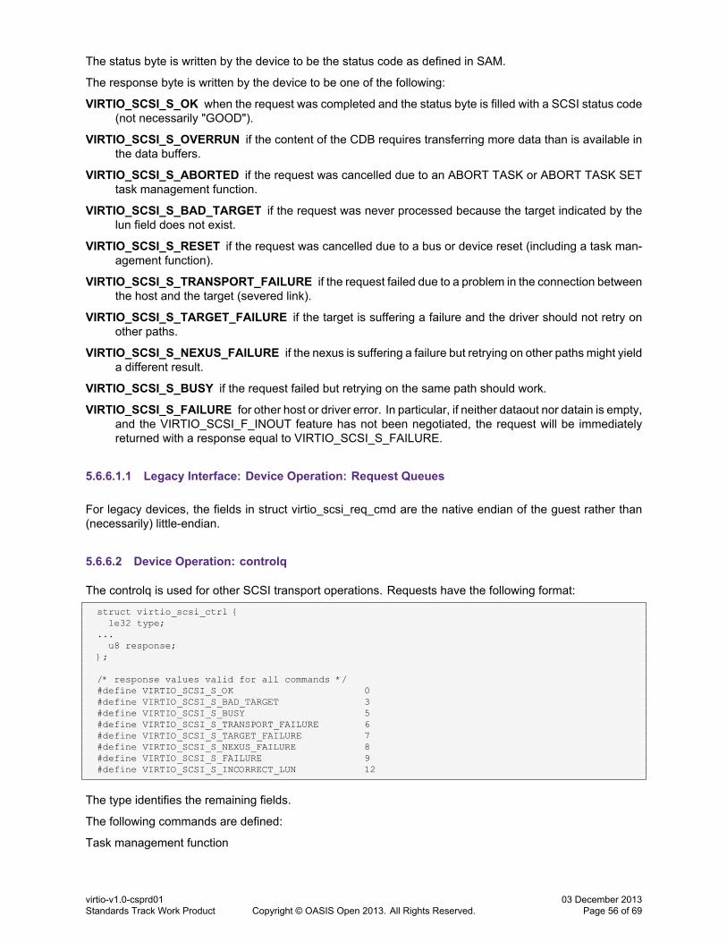
The status byte is written by the device to be the status code as defined in SAM.
The response byte is written by the device to be one of the following:
VIRTIO_SCSI_S_OK when the request was completed and the status byte is filled with a SCSI status code(not necessarily "GOOD").
VIRTIO_SCSI_S_OVERRUN if the content of the CDB requires transferring more data than is available inthe data buffers.
VIRTIO_SCSI_S_ABORTED if the request was cancelled due to an ABORT TASK or ABORT TASK SETtask management function.
VIRTIO_SCSI_S_BAD_TARGET if the request was never processed because the target indicated by thelun field does not exist.
VIRTIO_SCSI_S_RESET if the request was cancelled due to a bus or device reset (including a task man-agement function).
VIRTIO_SCSI_S_TRANSPORT_FAILURE if the request failed due to a problem in the connection betweenthe host and the target (severed link).
VIRTIO_SCSI_S_TARGET_FAILURE if the target is suffering a failure and the driver should not retry onother paths.
VIRTIO_SCSI_S_NEXUS_FAILURE if the nexus is suffering a failure but retrying on other paths might yielda different result.
VIRTIO_SCSI_S_BUSY if the request failed but retrying on the same path should work.
VIRTIO_SCSI_S_FAILURE for other host or driver error. In particular, if neither dataout nor datain is empty,and the VIRTIO_SCSI_F_INOUT feature has not been negotiated, the request will be immediatelyreturned with a response equal to VIRTIO_SCSI_S_FAILURE.
5.6.6.1.1 Legacy Interface: Device Operation: Request Queues
For legacy devices, the fields in struct virtio_scsi_req_cmd are the native endian of the guest rather than(necessarily) little-endian.
5.6.6.2 Device Operation: controlq
The controlq is used for other SCSI transport operations. Requests have the following format:
struct virtio_scsi_ctrl {le32 type;
...u8 response;
};
/* response values valid for all commands */#define VIRTIO_SCSI_S_OK 0#define VIRTIO_SCSI_S_BAD_TARGET 3#define VIRTIO_SCSI_S_BUSY 5#define VIRTIO_SCSI_S_TRANSPORT_FAILURE 6#define VIRTIO_SCSI_S_TARGET_FAILURE 7#define VIRTIO_SCSI_S_NEXUS_FAILURE 8#define VIRTIO_SCSI_S_FAILURE 9#define VIRTIO_SCSI_S_INCORRECT_LUN 12
The type identifies the remaining fields.
The following commands are defined:
Task management function
virtio-v1.0-csprd01Standards Track Work Product Copyright © OASIS Open 2013. All Rights Reserved.
03 December 2013Page 56 of 69

#define VIRTIO_SCSI_T_TMF 0
#define VIRTIO_SCSI_T_TMF_ABORT_TASK 0#define VIRTIO_SCSI_T_TMF_ABORT_TASK_SET 1#define VIRTIO_SCSI_T_TMF_CLEAR_ACA 2#define VIRTIO_SCSI_T_TMF_CLEAR_TASK_SET 3#define VIRTIO_SCSI_T_TMF_I_T_NEXUS_RESET 4#define VIRTIO_SCSI_T_TMF_LOGICAL_UNIT_RESET 5#define VIRTIO_SCSI_T_TMF_QUERY_TASK 6#define VIRTIO_SCSI_T_TMF_QUERY_TASK_SET 7
struct virtio_scsi_ctrl_tmf{
// Read-only partle32 type;le32 subtype;u8 lun[8];le64 id;// Write-only partu8 response;
}
/* command-specific response values */#define VIRTIO_SCSI_S_FUNCTION_COMPLETE 0#define VIRTIO_SCSI_S_FUNCTION_SUCCEEDED 10#define VIRTIO_SCSI_S_FUNCTION_REJECTED 11
The type is VIRTIO_SCSI_T_TMF; the subtype field defines. All fields except response are filled by thedriver. The subtype field must always be specified and identifies the requested task management function.
Other fields may be irrelevant for the requested TMF; if so, they are ignored but they should still be present.The lun field is in the same format specified for request queues; the single level LUN is ignored when thetask management function addresses a whole I_T nexus. When relevant, the value of the id field is matchedagainst the id values passed on the requestq.
The outcome of the task management function is written by the device in the response field. The command-specific response values map 1-to-1 with those defined in SAM.
Asynchronous notification query#define VIRTIO_SCSI_T_AN_QUERY 1
struct virtio_scsi_ctrl_an {// Read-only partle32 type;u8 lun[8];le32 event_requested;// Write-only partle32 event_actual;u8 response;
}
#define VIRTIO_SCSI_EVT_ASYNC_OPERATIONAL_CHANGE 2#define VIRTIO_SCSI_EVT_ASYNC_POWER_MGMT 4#define VIRTIO_SCSI_EVT_ASYNC_EXTERNAL_REQUEST 8#define VIRTIO_SCSI_EVT_ASYNC_MEDIA_CHANGE 16#define VIRTIO_SCSI_EVT_ASYNC_MULTI_HOST 32#define VIRTIO_SCSI_EVT_ASYNC_DEVICE_BUSY 64
By sending this command, the driver asks the device which events the given LUN can report, as describedin paragraphs 6.6 and A.6 of the SCSI MMC specification. The driver writes the events it is interested in intothe event_requested; the device responds by writing the events that it supports into event_actual.
The type is VIRTIO_SCSI_T_AN_QUERY. The lun and event_requested fields are written by the driver.The event_actual and response fields are written by the device.
No command-specific values are defined for the response byte.
Asynchronous notification subscription
virtio-v1.0-csprd01Standards Track Work Product Copyright © OASIS Open 2013. All Rights Reserved.
03 December 2013Page 57 of 69

#define VIRTIO_SCSI_T_AN_SUBSCRIBE 2
struct virtio_scsi_ctrl_an {// Read-only partle32 type;u8 lun[8];le32 event_requested;// Write-only partle32 event_actual;u8 response;
}
By sending this command, the driver asks the specified LUN to report events for its physical interface,again as described in the SCSI MMC specification. The driver writes the events it is interested in into theevent_requested; the device responds by writing the events that it supports into event_actual.
Event types are the same as for the asynchronous notification query message.
The type is VIRTIO_SCSI_T_AN_SUBSCRIBE. The lun and event_requested fields are written by the driver.The event_actual and response fields are written by the device.
No command-specific values are defined for the response byte.
5.6.6.2.1 Legacy Interface: Device Operation: controlq
For legacy devices, the fields in struct virtio_scsi_ctrl, struct virtio_scsi_ctrl_tmf, struct virtio_scsi_ctrl_anand struct virtio_scsi_ctrl_an are the native endian of the guest rather than (necessarily) little-endian.
5.6.6.3 Device Operation: eventq
The eventq is used by the device to report information on logical units that are attached to it. The drivershould always leave a few buffers ready in the eventq. In general, the device will not queue events tocope with an empty eventq, and will end up dropping events if it finds no buffer ready. However, whenreporting events for many LUNs (e.g. when a whole target disappears), the device can throttle events toavoid dropping them. For this reason, placing 10-15 buffers on the event queue should be enough.
Buffers are placed in the eventq and filled by the device when interesting events occur. The buffers shouldbe strictly write-only (device-filled) and the size of the buffers should be at least the value given in the device'sconfiguration information.
Buffers returned by the device on the eventq will be referred to as "events" in the rest of this section. Eventshave the following format:#define VIRTIO_SCSI_T_EVENTS_MISSED 0x80000000
struct virtio_scsi_event {// Write-only partle32 event;u8 lun[8];le32 reason;
}
If bit 31 is set in the event field, the device failed to report an event due to missing buffers. In this case,the driver should poll the logical units for unit attention conditions, and/or do whatever form of bus scan isappropriate for the guest operating system.
Themeaning of the reason field depends on the contents of the event field. The following events are defined:
No event#define VIRTIO_SCSI_T_NO_EVENT 0
This event is fired in the following cases:
virtio-v1.0-csprd01Standards Track Work Product Copyright © OASIS Open 2013. All Rights Reserved.
03 December 2013Page 58 of 69

• When the device detects in the eventq a buffer that is shorter than what is indicated in the configurationfield, it might use it immediately and put this dummy value in the event field. A well-written driver willnever observe this situation.
• When events are dropped, the device may signal this event as soon as the drivers makes a bufferavailable, in order to request action from the driver. In this case, of course, this event will be reportedwith the VIRTIO_SCSI_T_EVENTS_MISSED flag.
Transport reset
#define VIRTIO_SCSI_T_TRANSPORT_RESET 1
#define VIRTIO_SCSI_EVT_RESET_HARD 0#define VIRTIO_SCSI_EVT_RESET_RESCAN 1#define VIRTIO_SCSI_EVT_RESET_REMOVED 2
By sending this event, the device signals that a logical unit on a target has been reset, including the caseof a new device appearing or disappearing on the bus.The device fills in all fields. The event field is set toVIRTIO_SCSI_T_TRANSPORT_RESET. The lun field addresses a logical unit in the SCSI host.
The reason value is one of the three #define values appearing above:
• VIRTIO_SCSI_EVT_RESET_REMOVED (“LUN/target removed”) is used if the target or logical unit isno longer able to receive commands.
• VIRTIO_SCSI_EVT_RESET_HARD (“LUN hard reset”) is used if the logical unit has been reset, butis still present.
• VIRTIO_SCSI_EVT_RESET_RESCAN (“rescan LUN/target”) is used if a target or logical unit has justappeared on the device.
The “removed” and “rescan” events, when sent for LUN 0, may apply to the entire target. After receiving themthe driver should ask the initiator to rescan the target, in order to detect the case when an entire target hasappeared or disappeared. These two events will never be reported unless the VIRTIO_SCSI_F_HOTPLUGfeature was negotiated between the device and the driver.
Events will also be reported via sense codes (this obviously does not apply to newly appeared buses ortargets, since the application has never discovered them):
• “LUN/target removed” maps to sense key ILLEGAL REQUEST, asc 0x25, ascq 0x00 (LOGICAL UNITNOT SUPPORTED)
• “LUN hard reset” maps to sense key UNIT ATTENTION, asc 0x29 (POWER ON, RESET OR BUSDEVICE RESET OCCURRED)
• “rescan LUN/target” maps to sense key UNIT ATTENTION, asc 0x3f, ascq 0x0e (REPORTED LUNSDATA HAS CHANGED)
The preferred way to detect transport reset is always to use events, because sense codes are only seen bythe driver when it sends a SCSI command to the logical unit or target. However, in case events are dropped,the initiator will still be able to synchronize with the actual state of the controller if the driver asks the initiatorto rescan of the SCSI bus. During the rescan, the initiator will be able to observe the above sense codes,and it will process them as if it the driver had received the equivalent event.
Asynchronous notification
#define VIRTIO_SCSI_T_ASYNC_NOTIFY 2
By sending this event, the device signals that an asynchronous event was fired from a physical interface.
All fields are written by the device. The event field is set to VIRTIO_SCSI_T_ASYNC_NOTIFY. The lunfield addresses a logical unit in the SCSI host. The reason field is a subset of the events that the driver hassubscribed to via the "Asynchronous notification subscription" command.
When dropped events are reported, the driver should poll for asynchronous events manually using SCSIcommands.
virtio-v1.0-csprd01Standards Track Work Product Copyright © OASIS Open 2013. All Rights Reserved.
03 December 2013Page 59 of 69
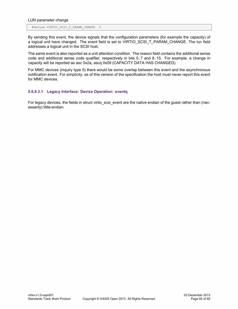
LUN parameter change
#define VIRTIO_SCSI_T_PARAM_CHANGE 3
By sending this event, the device signals that the configuration parameters (for example the capacity) ofa logical unit have changed. The event field is set to VIRTIO_SCSI_T_PARAM_CHANGE. The lun fieldaddresses a logical unit in the SCSI host.
The same event is also reported as a unit attention condition. The reason field contains the additional sensecode and additional sense code qualifier, respectively in bits 0..7 and 8..15. For example, a change incapacity will be reported as asc 0x2a, ascq 0x09 (CAPACITY DATA HAS CHANGED).
For MMC devices (inquiry type 5) there would be some overlap between this event and the asynchronousnotification event. For simplicity, as of this version of the specification the host must never report this eventfor MMC devices.
5.6.6.3.1 Legacy Interface: Device Operation: eventq
For legacy devices, the fields in struct virtio_scsi_event are the native endian of the guest rather than (nec-essarily) little-endian.
virtio-v1.0-csprd01Standards Track Work Product Copyright © OASIS Open 2013. All Rights Reserved.
03 December 2013Page 60 of 69
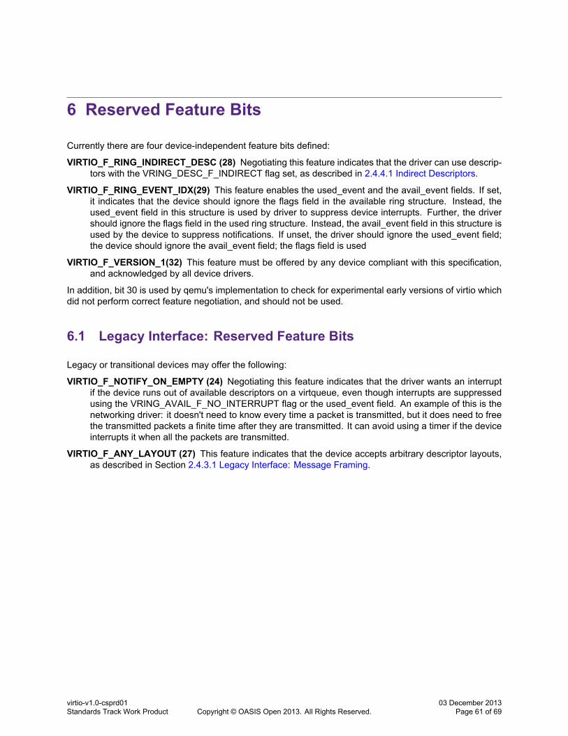
6 Reserved Feature Bits
Currently there are four device-independent feature bits defined:
VIRTIO_F_RING_INDIRECT_DESC (28) Negotiating this feature indicates that the driver can use descrip-tors with the VRING_DESC_F_INDIRECT flag set, as described in 2.4.4.1 Indirect Descriptors.
VIRTIO_F_RING_EVENT_IDX(29) This feature enables the used_event and the avail_event fields. If set,it indicates that the device should ignore the flags field in the available ring structure. Instead, theused_event field in this structure is used by driver to suppress device interrupts. Further, the drivershould ignore the flags field in the used ring structure. Instead, the avail_event field in this structure isused by the device to suppress notifications. If unset, the driver should ignore the used_event field;the device should ignore the avail_event field; the flags field is used
VIRTIO_F_VERSION_1(32) This feature must be offered by any device compliant with this specification,and acknowledged by all device drivers.
In addition, bit 30 is used by qemu's implementation to check for experimental early versions of virtio whichdid not perform correct feature negotiation, and should not be used.
6.1 Legacy Interface: Reserved Feature Bits
Legacy or transitional devices may offer the following:
VIRTIO_F_NOTIFY_ON_EMPTY (24) Negotiating this feature indicates that the driver wants an interruptif the device runs out of available descriptors on a virtqueue, even though interrupts are suppressedusing the VRING_AVAIL_F_NO_INTERRUPT flag or the used_event field. An example of this is thenetworking driver: it doesn't need to know every time a packet is transmitted, but it does need to freethe transmitted packets a finite time after they are transmitted. It can avoid using a timer if the deviceinterrupts it when all the packets are transmitted.
VIRTIO_F_ANY_LAYOUT (27) This feature indicates that the device accepts arbitrary descriptor layouts,as described in Section 2.4.3.1 Legacy Interface: Message Framing.
virtio-v1.0-csprd01Standards Track Work Product Copyright © OASIS Open 2013. All Rights Reserved.
03 December 2013Page 61 of 69
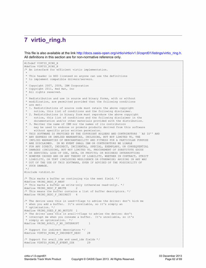
7 virtio_ring.h
This file is also available at the link http://docs.oasis-open.org/virtio/virtio/v1.0/csprd01/listings/virtio_ring.h.All definitions in this section are for non-normative reference only.
#ifndef VIRTIO_RING_H#define VIRTIO_RING_H/* An interface for efficient virtio implementation.** This header is BSD licensed so anyone can use the definitions* to implement compatible drivers/servers.** Copyright 2007, 2009, IBM Corporation* Copyright 2011, Red Hat, Inc* All rights reserved.** Redistribution and use in source and binary forms, with or without* modification, are permitted provided that the following conditions* are met:* 1. Redistributions of source code must retain the above copyright* notice, this list of conditions and the following disclaimer.* 2. Redistributions in binary form must reproduce the above copyright* notice, this list of conditions and the following disclaimer in the* documentation and/or other materials provided with the distribution.* 3. Neither the name of IBM nor the names of its contributors* may be used to endorse or promote products derived from this software* without specific prior written permission.* THIS SOFTWARE IS PROVIDED BY THE COPYRIGHT HOLDERS AND CONTRIBUTORS ``AS IS'' AND* ANY EXPRESS OR IMPLIED WARRANTIES, INCLUDING, BUT NOT LIMITED TO, THE* IMPLIED WARRANTIES OF MERCHANTABILITY AND FITNESS FOR A PARTICULAR PURPOSE* ARE DISCLAIMED. IN NO EVENT SHALL IBM OR CONTRIBUTORS BE LIABLE* FOR ANY DIRECT, INDIRECT, INCIDENTAL, SPECIAL, EXEMPLARY, OR CONSEQUENTIAL* DAMAGES (INCLUDING, BUT NOT LIMITED TO, PROCUREMENT OF SUBSTITUTE GOODS* OR SERVICES; LOSS OF USE, DATA, OR PROFITS; OR BUSINESS INTERRUPTION)* HOWEVER CAUSED AND ON ANY THEORY OF LIABILITY, WHETHER IN CONTRACT, STRICT* LIABILITY, OR TORT (INCLUDING NEGLIGENCE OR OTHERWISE) ARISING IN ANY WAY* OUT OF THE USE OF THIS SOFTWARE, EVEN IF ADVISED OF THE POSSIBILITY OF* SUCH DAMAGE.*/#include <stdint.h>
/* This marks a buffer as continuing via the next field. */#define VRING_DESC_F_NEXT 1/* This marks a buffer as write-only (otherwise read-only). */#define VRING_DESC_F_WRITE 2/* This means the buffer contains a list of buffer descriptors. */#define VRING_DESC_F_INDIRECT 4
/* The device uses this in used->flags to advise the driver: don't kick me* when you add a buffer. It's unreliable, so it's simply an* optimization. */#define VRING_USED_F_NO_NOTIFY 1/* The driver uses this in avail->flags to advise the device: don't* interrupt me when you consume a buffer. It's unreliable, so it's* simply an optimization. */#define VRING_AVAIL_F_NO_INTERRUPT 1
/* Support for indirect descriptors */#define VIRTIO_RING_F_INDIRECT_DESC 28
/* Support for avail_idx and used_idx fields */#define VIRTIO_RING_F_EVENT_IDX 29
virtio-v1.0-csprd01Standards Track Work Product Copyright © OASIS Open 2013. All Rights Reserved.
03 December 2013Page 62 of 69

/* Arbitrary descriptor layouts. */#define VIRTIO_F_ANY_LAYOUT 27
/* Virtio ring descriptors: 16 bytes.* These can chain together via "next". */struct vring_desc {
/* Address (guest-physical). */le64 addr;/* Length. */le32 len;/* The flags as indicated above. */le16 flags;/* We chain unused descriptors via this, too */le16 next;
};
struct vring_avail {le16 flags;le16 idx;le16 ring[];/* Only if VIRTIO_RING_F_EVENT_IDX: le16 used_event; */
};
/* le32 is used here for ids for padding reasons. */struct vring_used_elem {
/* Index of start of used descriptor chain. */le32 id;/* Total length of the descriptor chain which was written to. */le32 len;
};
struct vring_used {le16 flags;le16 idx;struct vring_used_elem ring[];/* Only if VIRTIO_RING_F_EVENT_IDX: le16 avail_event; */
};
struct vring {unsigned int num;
struct vring_desc *desc;struct vring_avail *avail;struct vring_used *used;
};
/* The standard layout for the ring is a continuous chunk of memory which* looks like this. We assume num is a power of 2.** struct vring {* // The actual descriptors (16 bytes each)* struct vring_desc desc[num];** // A ring of available descriptor heads with free-running index.* le16 avail_flags;* le16 avail_idx;* le16 available[num];* le16 used_event_idx; // Only if VIRTIO_RING_F_EVENT_IDX** // Padding to the next align boundary.* char pad[];** // A ring of used descriptor heads with free-running index.* le16 used_flags;* le16 used_idx;* struct vring_used_elem used[num];* le16 avail_event_idx; // Only if VIRTIO_RING_F_EVENT_IDX* };* Note: for virtio PCI, align is 4096.*/static inline void vring_init(struct vring *vr, unsigned int num, void *p,
unsigned long align)
virtio-v1.0-csprd01Standards Track Work Product Copyright © OASIS Open 2013. All Rights Reserved.
03 December 2013Page 63 of 69

{vr->num = num;vr->desc = p;vr->avail = p + num*sizeof(struct vring_desc);vr->used = (void *)(((unsigned long)&vr->avail->ring[num] + sizeof(le16)
+ align-1)& ~(align - 1));
}
static inline unsigned vring_size(unsigned int num, unsigned long align){
return ((sizeof(struct vring_desc)*num + sizeof(le16)*(3+num)+ align - 1) & ~(align - 1))
+ sizeof(le16)*3 + sizeof(struct vring_used_elem)*num;}
static inline int vring_need_event(uint16_t event_idx, uint16_t new_idx, uint16_t old_idx){
return (uint16_t)(new_idx - event_idx - 1) < (uint16_t)(new_idx - old_idx);}
/* Get location of event indices (only with VIRTIO_RING_F_EVENT_IDX) */static inline le16 *vring_used_event(struct vring *vr){
/* For backwards compat, used event index is at *end* of avail ring. */return &vr->avail->ring[vr->num];
}
static inline le16 *vring_avail_event(struct vring *vr){
/* For backwards compat, avail event index is at *end* of used ring. */return (le16 *)&vr->used->ring[vr->num];
}#endif /* VIRTIO_RING_H */
virtio-v1.0-csprd01Standards Track Work Product Copyright © OASIS Open 2013. All Rights Reserved.
03 December 2013Page 64 of 69
8 Creating New Device Types
Various considerations are necessary when creating a new device type.
8.1 How Many Virtqueues?
It is possible that a very simple device will operate entirely through its configuration space, but most will needat least one virtqueue in which it will place requests. A device with both input and output (eg. console andnetwork devices described here) need two queues: one which the driver fills with buffers to receive input,and one which the driver places buffers to transmit output.
8.2 What Configuration Space Layout?
Configuration space should only be used for initialization-time parameters. It is a limited resource with nosynchronization betweenwritable fields, so for most uses it is better to use a virtqueue to update configurationinformation (the network device does this for filtering, otherwise the table in the config space could potentiallybe very large).
Devices must not assume that configuration fields over 32 bits wide are atomically writable.
8.3 What Device Number?
Device numbers can be reserved by the OASIS committee: email [email protected] to securea unique one.
Meanwhile for experimental drivers, use 65535 and work backwards.
8.4 How many MSI-X vectors? (for PCI)
Using the optional MSI-X capability devices can speed up interrupt processing by removing the need toread ISR Status register by guest driver (which might be an expensive operation), reducing interrupt sharingbetween devices and queues within the device, and handling interrupts frommultiple CPUs. However, somesystems impose a limit (which might be as low as 256) on the total number of MSI-X vectors that can beallocated to all devices. Devices and/or drivers should take this into account, limiting the number of vectorsused unless the device is expected to cause a high volume of interrupts. Devices can control the number ofvectors used by limiting the MSI-X Table Size or not presenting MSI-X capability in PCI configuration space.Drivers can control this by mapping events to as small number of vectors as possible, or disabling MSI-Xcapability altogether.
virtio-v1.0-csprd01Standards Track Work Product Copyright © OASIS Open 2013. All Rights Reserved.
03 December 2013Page 65 of 69

8.5 Device Improvements
Any change to configuration space, or new virtqueues, or behavioural changes, should be indicated bynegotiation of a new feature bit. This establishes clarity1 and avoids future expansion problems.
Clusters of functionality which are always implemented together can use a single bit, but if one featuremakes sense without the others they should not be gratuitously grouped together to conserve feature bits.
1Even if it does mean documenting design or implementation mistakes!
virtio-v1.0-csprd01Standards Track Work Product Copyright © OASIS Open 2013. All Rights Reserved.
03 December 2013Page 66 of 69

9 Conformance
An implementation conforms to this specification if it satisfies all of the MUST or REQUIRED level require-ments defined within this specification.
virtio-v1.0-csprd01Standards Track Work Product Copyright © OASIS Open 2013. All Rights Reserved.
03 December 2013Page 67 of 69

Appendix A. Acknowledgements
The following individuals have participated in the creation of this specification and are gratefully acknowl-edged:
Participants:Amit Shah, Red HatAmos Kong, Red HatAnthony Liguori, IBMBruce Rogers, NovellBryan Venteicher, NetAppCornelia Huck, IBMDaniel Kiper, OracleGeoff Brown, Machine-to-Machine Intelligence (M2MI) CorporationGershon Janssen, Individual MemberJames Bottomley, Parallels IP Holdings GmbHLuiz Capitulino, Red HatMichael S. Tsirkin, Red HatPaolo Bonzini, Red HatPawel Moll, ARM LimitedRusty Russell, IBMSasha Levin, OracleSergey Tverdyshev, Thales e-SecurityStefan Hajnoczi, Red HatTom Lyon, Samya Systems, Inc.
virtio-v1.0-csprd01Standards Track Work Product Copyright © OASIS Open 2013. All Rights Reserved.
03 December 2013Page 68 of 69
Appendix B. Revision History
Revision Date Editor Changes Made[Rev number ] [Rev Date ] [Modified By ] [Summary of Changes ]
virtio-v1.0-csprd01Standards Track Work Product Copyright © OASIS Open 2013. All Rights Reserved.
03 December 2013Page 69 of 69