· Typ-Nr. circuit drawing technical drawing mounting dimensions e illuminated-/pushbutton...
20
EAO Product Information 5AHEAI&"
Transcript of · Typ-Nr. circuit drawing technical drawing mounting dimensions e illuminated-/pushbutton...
Switches and Indicators 84
Switches and Indicators
53801.2002
Series 84
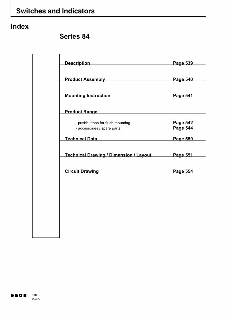
Description
Product Assembly
Mounting Instruction
Product Range
- pushbuttons for flush mounting- accessories / spare parts
Technical Data
Technical Drawing / Dimension / Layout
Circuit Drawing
Page 539
Page 540
Page 541
Page 550
Page 551
Page 554
Page 542Page 544
Index
Description 84
53901.2002
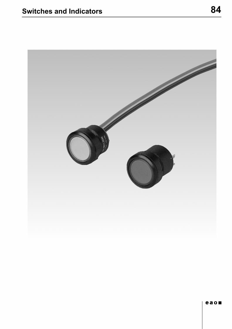
General informationThe 84 series is a modular system of pushbuttons consisting of len-ses, actuator elements, switching units and a variety of means of con-nection and mounting. The front protection IP 67 ensures that the illuminated pushbuttons are suited for industrial use. The IP 40 versi-on is available for reduced protection.
MountingThe actuators of the series 84 are inserted in the mounting hole 22.5 mm dia. and the switching units are clipped on to the rear of the actuators. The torque with which the fixing sleeve is tightened is max. 80 Ncm. The pushbutton system can be mounted as a complete unit (actuator and switching unit). Mounting from the front with the wiring already attached is also possible.When mounted on printed circuit boards the actuators are inserted in the mounting hole 22.5 mm dia. and the switching elements are fixed on the board. The PCB is connected to the preassembled actuator by means of the mounting flange. There is no need for subsequent ad-justment or spacing studs.
LensesThe flat lenses are available in various colours and made either from plastic, or anodized aluminium.
MarkingThe actuators of the series 84 can be marked by any of the following methods: engraving, hot pressing, laser, marking plate. .
Please provide marking details.
IlluminationTo ensure full illumination, the switching elements can be supplied with an integrated Multi-LED in any of the colours red, yellow, orange or green. LED load 20 mA (24 VDC) or 40 mA (12 VDC). Series re-sistor integrated.
Switching systemSnap-action blade switching system with 2 independent contact points and tactile operation. Guarantees reliable switching even of very light loads. Fitted with 1 normally open contact.
All dimensions in mm.We reserve the right to modify technical data.
Specimen orderIndicator
- indicator actuator, IP40 84-2101.0Recommended accessories:- lens plastic, yellow 84-7111.400- indicator element, IP40,
Multi-LED, yellow, soldering-/plug-in terminal 84-8102.4620
or
Indicator with PCB terminal- indicator actuator, IP40 84-2101.0Recommended accessories:- lens plastic yellow 84-7111.400- indicator element with
PCB terminal 92-800.042- LED, 1 chip, yellow 10-2602.3174D- mounting flange 92-960.0
84product assembly
54001.2002
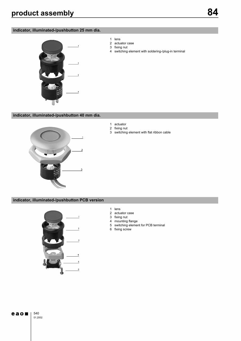
indicator, illuminated-/pushbutton 25 mm dia.
0
1 lens2 actuator case3 fixing nut4 switching element with soldering-/plug-in terminal
indicator, illuminated-/pushbutton 40 mm dia.
0
1 actuator2 fixing nut3 switching element with flat ribbon cable
indicator, illuminated-/pushbutton PCB version
0
1 lens2 actuator case3 fixing nut4 mounting flange5 switching element for PCB terminal6 fixing screw
Mounting Instruction 84
54101.2002
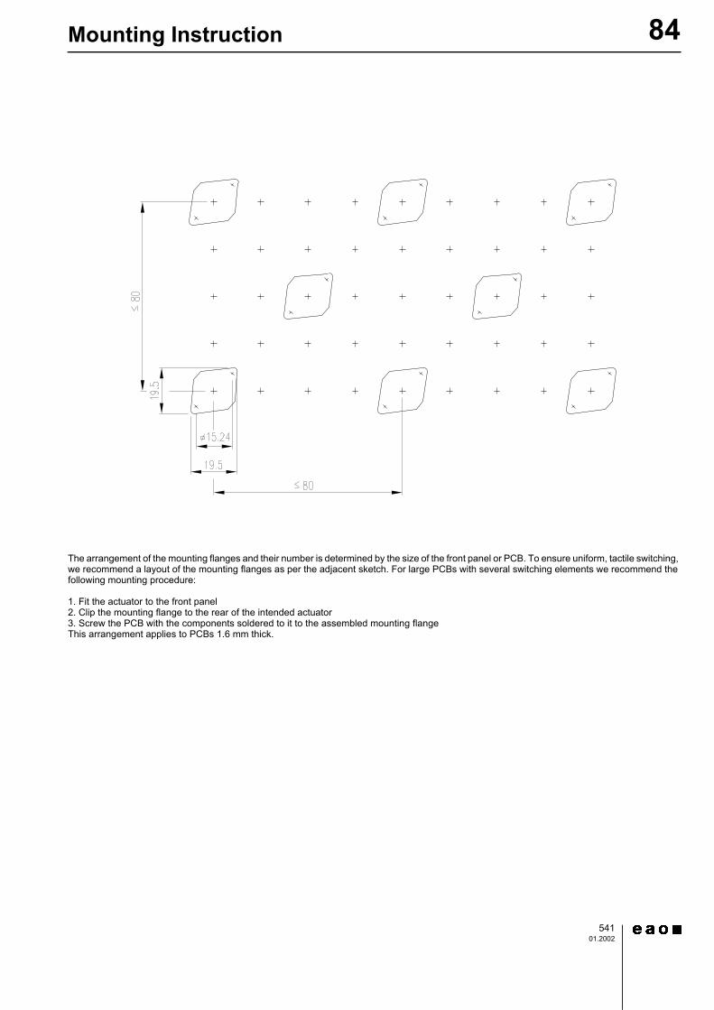
The arrangement of the mounting flanges and their number is determined by the size of the front panel or PCB. To ensure uniform, tactile switching, we recommend a layout of the mounting flanges as per the adjacent sketch. For large PCBs with several switching elements we recommend the following mounting procedure:
1. Fit the actuator to the front panel2. Clip the mounting flange to the rear of the intended actuator3. Screw the PCB with the components soldered to it to the assembled mounting flangeThis arrangement applies to PCBs 1.6 mm thick.
84Pushbuttons for Flush mounting
54201.2002
d lens plastic page 544d lens metal with window page 544d indicator element page 545d indicator element with PCB terminal page 546d LED page 547d mounting flange page 548
technical drawings from page 551, mounting dimensions from page 553
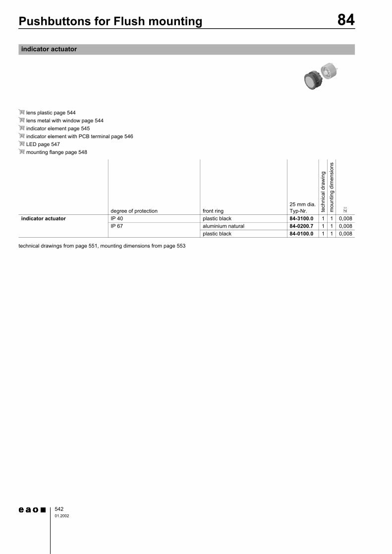
indicator actuator
degree of protection front ring25 mm dia.Typ-Nr. te
chni
cal d
raw
ing
mou
ntin
g di
men
sion
s
e
indicator actuator IP 40 plastic black 84-3100.0 1 1 0,008IP 67 aluminium natural 84-0200.7 1 1 0,008
plastic black 84-0100.0 1 1 0,008
84Pushbuttons for Flush mounting
54301.2002
d lens plastic page 544d lens metal with window page 544d lens metal page 544d switching element page 546d switching element with PCB terminal page 547d LED page 547d mounting flange page 548
switching action : momentary action = Mcircuit drawings from page 554, technical drawings from page 551, mounting dimensions from page 553
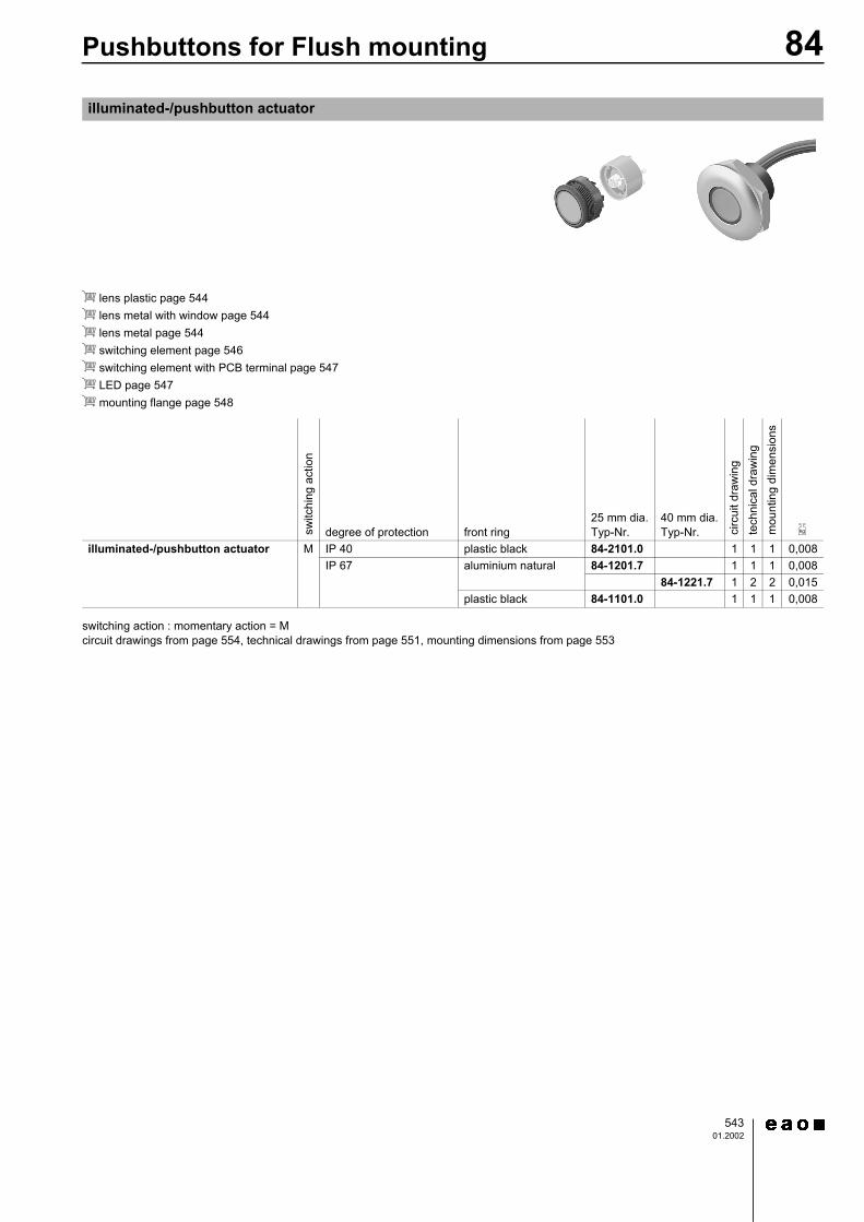
illuminated-/pushbutton actuator
switc
hing
act
ion
degree of protection front ring25 mm dia.Typ-Nr.
40 mm dia.Typ-Nr. ci
rcui
t dra
win
gte
chni
cal d
raw
ing
mou
ntin
g di
men
sion
s
e
illuminated-/pushbutton actuator M IP 40 plastic black 84-2101.0 1 1 1 0,008IP 67 aluminium natural 84-1201.7 1 1 1 0,008
84-1221.7 1 2 2 0,015plastic black 84-1101.0 1 1 1 0,008
54408.2002
84accessories
for lens, plastic
at front
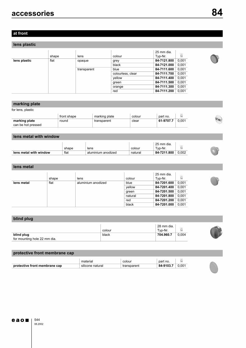
lens plastic
shape lens colour25 mm dia.Typ-Nr. e
lens plastic flat opaque grey 84-7121.800 0,001black 84-7121.000 0,001
transparent blue 84-7111.600 0,001colourless, clear 84-7111.700 0,001yellow 84-7111.400 0,001green 84-7111.500 0,001orange 84-7111.300 0,001red 84-7111.200 0,001
marking plate
front shape marking plate colour part no. e
marking platecan be hot pressed
round transparent clear 61-9707.7 0,001
lens metal with window
shape lens colour25 mm dia.Typ-Nr. e
lens metal with window flat aluminium anodized natural 84-7211.800 0,002
lens metal
shape lens colour25 mm dia.Typ-Nr. e
lens metal flat aluminium anodized blue 84-7201.600 0,001yellow 84-7201.400 0,001green 84-7201.500 0,001natural 84-7201.800 0,001red 84-7201.200 0,001black 84-7201.000 0,001
blind plug
colour28 mm dia.Typ-Nr. e
blind plugfor mounting hole 22 mm dia.
black 704.960.7 0,004
protective front membrane cap
material colour part no. e
protective front membrane cap silicone natural transparent 84-9103.7 0,001
54508.2002
84accessories
incl. illumination
circuit drawings from page 554, technical drawings from page 551
at back
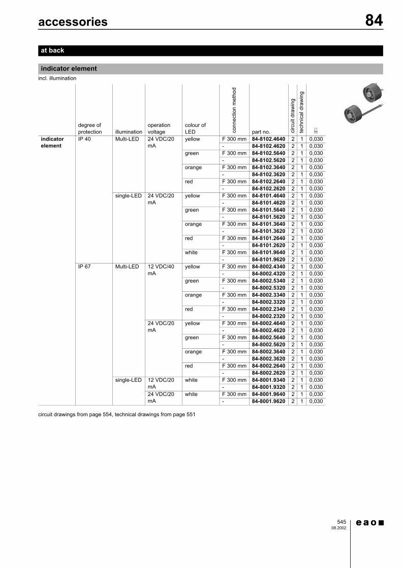
indicator element
degree of protection illumination
operation voltage
colour of LED co
nnec
tion
met
hod
part no. circ
uit d
raw
ing
tech
nica
l dra
win
g
e
indicator element
IP 40 Multi-LED 24 VDC/20 mA
yellow F 300 mm 84-8102.4640 2 1 0,030- 84-8102.4620 2 1 0,030
green F 300 mm 84-8102.5640 2 1 0,030- 84-8102.5620 2 1 0,030
orange F 300 mm 84-8102.3640 2 1 0,030- 84-8102.3620 2 1 0,030
red F 300 mm 84-8102.2640 2 1 0,030- 84-8102.2620 2 1 0,030
single-LED 24 VDC/20 mA
yellow F 300 mm 84-8101.4640 2 1 0,030- 84-8101.4620 2 1 0,030
green F 300 mm 84-8101.5640 2 1 0,030- 84-8101.5620 2 1 0,030
orange F 300 mm 84-8101.3640 2 1 0,030- 84-8101.3620 2 1 0,030
red F 300 mm 84-8101.2640 2 1 0,030- 84-8101.2620 2 1 0,030
white F 300 mm 84-8101.9640 2 1 0,030- 84-8101.9620 2 1 0,030
IP 67 Multi-LED 12 VDC/40 mA
yellow F 300 mm 84-8002.4340 2 1 0,030- 84-8002.4320 2 1 0,030
green F 300 mm 84-8002.5340 2 1 0,030- 84-8002.5320 2 1 0,030
orange F 300 mm 84-8002.3340 2 1 0,030- 84-8002.3320 2 1 0,030
red F 300 mm 84-8002.2340 2 1 0,030- 84-8002.2320 2 1 0,030
24 VDC/20 mA
yellow F 300 mm 84-8002.4640 2 1 0,030- 84-8002.4620 2 1 0,030
green F 300 mm 84-8002.5640 2 1 0,030- 84-8002.5620 2 1 0,030
orange F 300 mm 84-8002.3640 2 1 0,030- 84-8002.3620 2 1 0,030
red F 300 mm 84-8002.2640 2 1 0,030- 84-8002.2620 2 1 0,030
single-LED 12 VDC/20 mA
white F 300 mm 84-8001.9340 2 1 0,030- 84-8001.9320 2 1 0,030
24 VDC/20 mA
white F 300 mm 84-8001.9640 2 1 0,030- 84-8001.9620 2 1 0,030
54608.2002
84accessories
illumination and mounting flange to be ordered separately
technical drawings from page 551, component layouts from page 553
circuit drawings from page 554, technical drawings from page 551
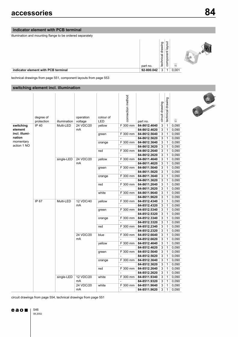
indicator element with PCB terminal
part no. tech
nica
l dra
win
gco
mpo
nent
layo
ut
e
indicator element with PCB terminal 92-800.042 3 1 0,001
switching element incl. illumination
degree of protection illumination
operation voltage
colour of LED co
nnec
tion
met
hod
part no. circ
uit d
raw
ing
tech
nica
l dra
win
g
e
switching element incl. illumi-nationmomentary action 1 NO
IP 40 Multi-LED 24 VDC/20 mA
yellow F 300 mm 84-8612.4640 3 1 0,090- 84-8612.4620 3 1 0,090
green F 300 mm 84-8612.5640 3 1 0,090- 84-8612.5620 3 1 0,090
orange F 300 mm 84-8612.3640 3 1 0,090- 84-8612.3620 3 1 0,090
red F 300 mm 84-8612.2640 3 1 0,090- 84-8612.2620 3 1 0,090
single-LED 24 VDC/20 mA
yellow F 300 mm 84-8611.4640 3 1 0,090- 84-8611.4620 3 1 0,090
green F 300 mm 84-8611.5640 3 1 0,090- 84-8611.5620 3 1 0,090
orange F 300 mm 84-8611.3640 3 1 0,090- 84-8611.3620 3 1 0,090
red F 300 mm 84-8611.2640 3 1 0,090- 84-8611.2620 3 1 0,090
white F 300 mm 84-8611.9640 3 1 0,090- 84-8611.9620 3 1 0,090
IP 67 Multi-LED 12 VDC/40 mA
yellow F 300 mm 84-8512.4340 3 1 0,090- 84-8512.4320 3 1 0,090
green F 300 mm 84-8512.5340 3 1 0,090- 84-8512.5320 3 1 0,090
orange F 300 mm 84-8512.3340 3 1 0,090- 84-8512.3320 3 1 0,090
red F 300 mm 84-8512.2340 3 1 0,090- 84-8512.2320 3 1 0,090
24 VDC/20 mA
blue F 300 mm 84-8512.6640 3 1 0,090- 84-8512.6620 3 1 0,090
yellow F 300 mm 84-8512.4640 3 1 0,090- 84-8512.4620 3 1 0,090
green F 300 mm 84-8512.5640 3 1 0,090- 84-8512.5620 3 1 0,090
orange F 300 mm 84-8512.3640 3 1 0,090- 84-8512.3620 3 1 0,090
red F 300 mm 84-8512.2640 3 1 0,090- 84-8512.2620 3 1 0,090
single-LED 12 VDC/20 mA
white F 300 mm 84-8511.9340 3 1 0,090- 84-8511.9320 3 1 0,090
24 VDC/20 mA
white F 300 mm 84-8511.9640 3 1 0,090- 84-8511.9620 3 1 0,090
54708.2002
84accessories
circuit drawings from page 554, technical drawings from page 551
illumination and mounting flange to be ordered separately
circuit drawings from page 554, technical drawings from page 551, component layouts from page 553
for indicator/switching element with PCB terminal
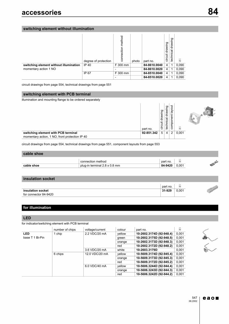
switching element without illumination
degree of protection conn
ectio
n m
etho
d
photo part no. circ
uit d
raw
ing
tech
nica
l dra
win
g
e
switching element without illuminationmomentary action 1 NO
IP 40 F 300 mm 84-8610.0040 4 1 0,090- 84-8610.0020 4 1 0,090
IP 67 F 300 mm 84-8510.0040 4 1 0,090- 84-8510.0020 4 1 0,090
switching element with PCB terminal
part no. circ
uit d
raw
ing
tech
nica
l dra
win
gco
mpo
nent
layo
ut
e
switching element with PCB terminalmomentary action, 1 NO, front protection IP 40
92-851.342 5 4 2 0,001
cable shoe
connection method part no. e
cable shoe plug-in terminal 2.8 x 0.8 mm 84-9420 0,001
insulation socket
part no. e
insulation socketfor connector 84-9420
31-929 0,001
for illumination
LED
number of chips voltage/current colour part no. e
LEDbase T 1 Bi-Pin
1 chip 2.2 VDC/20 mA yellow 10-2602.3174D (92-948.4) 0,001green 10-2602.3175D (92-948.5) 0,001orange 10-2602.3173D (92-948.3) 0,001red 10-2602.3172D (92-948.2) 0,001
3.6 VDC/20 mA white 10-2603.3179D 0,0016 chips 12.0 VDC/20 mA yellow 10-5609.3174D (92-945.4) 0,001
orange 10-5609.3173D (92-945.3) 0,001red 10-5609.3172D (92-945.2) 0,001
6.0 VDC/40 mA yellow 10-5606.3244D (92-944.4) 0,001orange 10-5606.3243D (92-944.3) 0,001red 10-5606.3242D (92-944.2) 0,001
54808.2002
84accessories
for indicator/switching element with PCB terminal
technical drawings from page 551
technical drawings from page 551
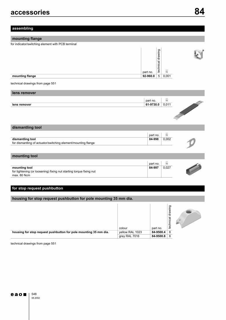
assembling
mounting flange
part no. tech
nica
l dra
win
g
e
mounting flange 92-960.0 5 0,001
lens remover
part no. e
lens remover 61-9730.0 0,011
dismantling tool
part no. e
dismantling toolfor dismantling of actuator/switching element/mounting flange
84-998 0,002
mounting tool
part no. e
mounting toolfor tightening (or loosening) fixing nut starting torque fixing nutmax. 80 Ncm
84-997 0,027
for stop request pushbutton
housing for stop request pushbutton for pole mounting 35 mm dia.
colour part no. tech
nica
l dra
win
g
housing for stop request pushbutton for pole mounting 35 mm dia. yellow RAL 1023 84-9500.4 6grey RAL 7016 84-9500.8 6
54908.2002
84accessories
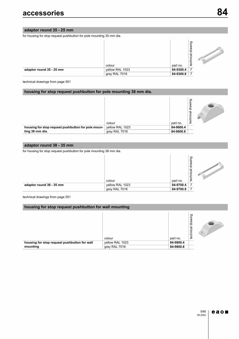
for housing for stop request pushbutton for pole mounting 35 mm dia.
technical drawings from page 551
for housing for stop request pushbutton for pole mounting 38 mm dia.
technical drawings from page 551
adaptor round 35 - 25 mm
colour part no. tech
nica
l dra
win
g
adaptor round 35 - 25 mm yellow RAL 1023 84-9300.4 7grey RAL 7016 84-9300.8 7
housing for stop request pushbutton for pole mounting 38 mm dia.
colour part no. tech
nica
l dra
win
g
housing for stop request pushbutton for pole moun-ting 38 mm dia.
yellow RAL 1023 84-9600.4grey RAL 7016 84-9600.8
adaptor round 38 - 35 mm
colour part no. tech
nica
l dra
win
g
adaptor round 38 - 35 mm yellow RAL 1023 84-9700.4 7grey RAL 7016 84-9700.8 7
housing for stop request pushbutton for wall mounting
colour part no. tech
nica
l dra
win
g
housing for stop request pushbutton for wall mounting
yellow RAL 1023 84-9800.4grey RAL 7016 84-9800.8
55011.2002
84technical data
switching system
Short-travel switching system with 2 independent contact points and tactile operation.Guarantees reliable switching even of very light loads.Fitted with 1 normally open contact.
material
material of contactsgold
switching elementthermoplastic polyester PET, PBT and polyacetale POM
mechanical characteristics
connection methodplug-in/soldering terminals 2.8 x 0.8 mmflat ribbon cable connectorsPCB terminals
wire cross-section0,5 mm2
actuating force4.0 N ± 0.2 (measured at the lens)
actuating travelswitching element 0.5 mm
storage temperature-40°C to + 85°C(as per DIN IEC 68-)
resistance to heat of soldering260°C/5 s as per IEC 68-2-20 (PCB assembly)350°C/10 s as per IEC 68-2-20 (when using a soldering iron)
mechanical life>= 1 million operations as per IEC 512-5, test 9a
rebound time<=1 ms
resistance to shock50 g for 11 ms as per IEC 68-2-29 and 27
resistance to vibration10 g at 10-2000 Hz, amplitude 0.75 mm as per IEC 68-2-6
service temperature-25°C to + 70°C(as per DIN IEC 68-)
electrical characteristics
contact resistancestarting value (initial) <= 100 mΩ as per IEC 512-2, test 2b
electrical life>= 500.000 operations at 42 VDC/50 mA as per IEC 512-5, test 9c
insulation resistance>= 1.000.000.000 ohm between all terminals at 100 VDC, as per IEC 512-2, test 3a
switch rating0
electric strength500 VAC, 50 Hz, 1 min, as per IEC 512-2, test 3a
material
lensespolycarbonate PC or aluminium
actuator casepolyetherimide PEI or aluminium
mechanical characteristics
actuating force4.0 N ± 0.2 (measured at the lens)
actuating traveltotal switching travel 1.2 mm
storage temperature-40°C to + 85°C(as per DIN IEC 68-)
mechanical life>= 1 million operations as per IEC 512-5, test 9a
degree of protectionfront as per IEC 529IP 67, IP 65 and IP40
service temperature-25°C to + 70°C(as per DIN IEC 68-)
electrical characteristics
electrostatic breakdown value0
switching element switching voltage VDC/VAC min. 50 mV, max. 42 Vswitching current VDC/VAC min.10 mA, max.100 mApower rating max. 2 W
actuator with snap-action switching element
plastic case >= 15 kV as per IEC 801-2aluminium case >= 5 kV as per IEC 801-2(mounted in plastic front panel)
84drawings
55101.2002
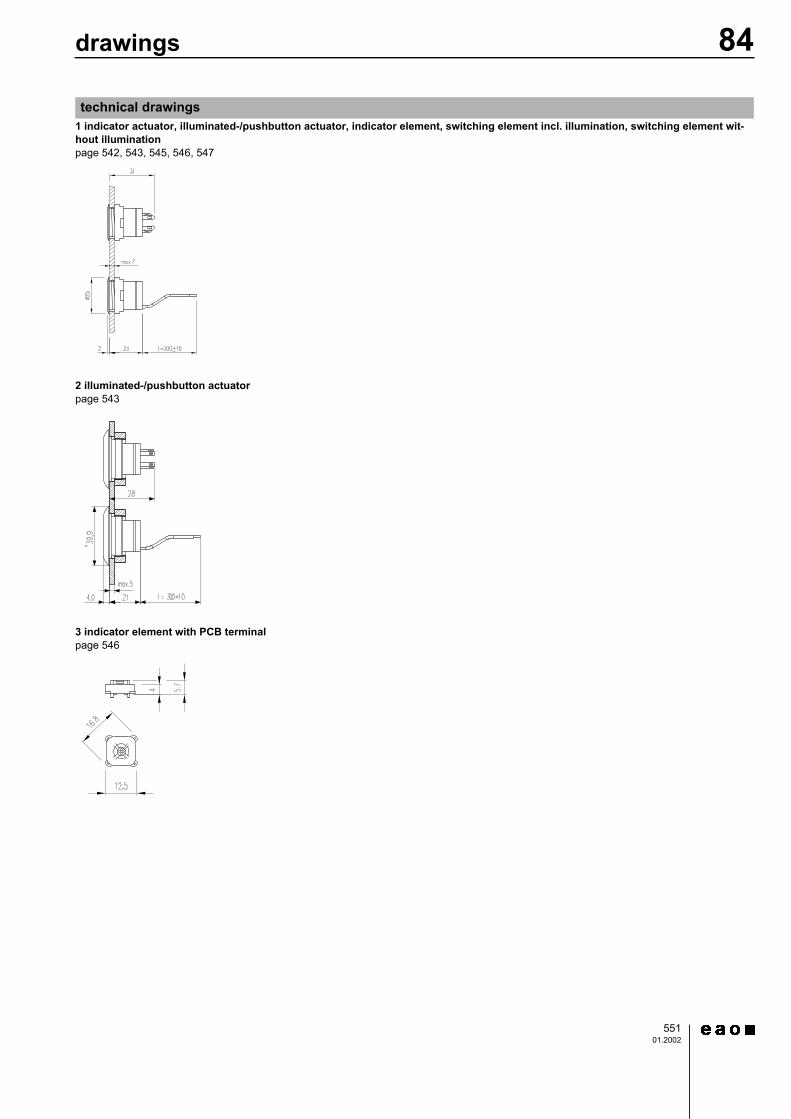
1 indicator actuator, illuminated-/pushbutton actuator, indicator element, switching element incl. illumination, switching element wit-hout illuminationpage 542, 543, 545, 546, 547
2 illuminated-/pushbutton actuatorpage 543
3 indicator element with PCB terminalpage 546
technical drawings
84drawings
55201.2002
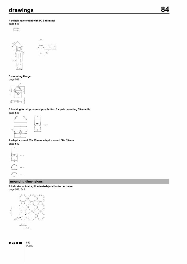
4 switching element with PCB terminalpage 546
5 mounting flangepage 548
6 housing for stop request pushbutton for pole mounting 35 mm dia.page 548
7 adaptor round 35 - 25 mm, adaptor round 38 - 35 mm page 549
1 indicator actuator, illuminated-/pushbutton actuatorpage 542, 543
mounting dimensions
84drawings
55301.2002
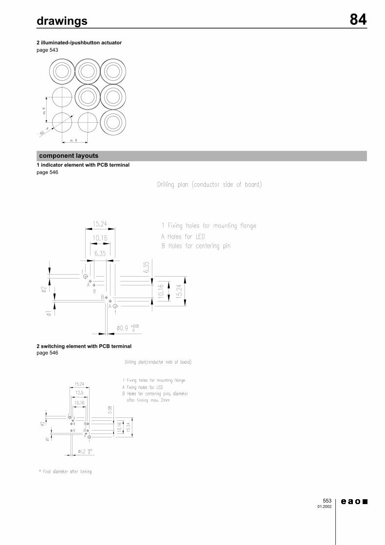
2 illuminated-/pushbutton actuatorpage 543
1 indicator element with PCB terminalpage 546
2 switching element with PCB terminalpage 546
component layouts
84drawings
55401.2002
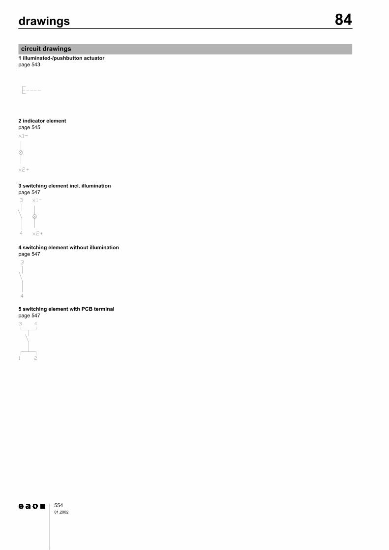
1 illuminated-/pushbutton actuatorpage 543
2 indicator elementpage 545
3 switching element incl. illuminationpage 547
4 switching element without illuminationpage 547
5 switching element with PCB terminalpage 547
circuit drawings
! "#$ %
" ! &' #$ ((
! &&#$
'! "&#$
!" '"#$ )
! !&"&#$
"# !#$
"#$ ! '"#$
% & ! #$ *(
%" ! && "&&#$ *
+, ! '
#$ -%