@ The SiD detector concept : An Introduction Harry Weerts Argonne National Laboratory.
63
@ The SiD detector concept : An Introduction Harry Weerts Argonne National Laboratory
-
Upload
gabriella-davidson -
Category
Documents
-
view
223 -
download
1
Transcript of @ The SiD detector concept : An Introduction Harry Weerts Argonne National Laboratory.

@
The SiD detector concept :
An Introduction
Harry Weerts
Argonne National Laboratory
2 SiD in France, 11 Feb 2008 H.Weerts
Outline
The SiD detector concept
Introduction to ILCrecent goal changes
Detector Requirements
SiD assumptionsDetector description & performance
Later in day:Areas for collaborationFuture plans

3 SiD in France, 11 Feb 2008 H.Weerts
LHC potential and need for ILC
The Large Hadron Collider (LHC), will open window to “remainder” of and physics “beyond” the Standard Model.
Completing the Standard Model and the symmetries underlying it plus their required breaking leads us to expect a plethora of new physics.
This is the energy/mass regime from ~0.5Tev to a few TeV
Starting in 2008…..
LHC will discover them or give clear indications that they exist.
new particles and fields in this energy range
We will need a tool to measure precisely and unambiguously their properties and couplings i.e. identify physics.
This is an e+e- machine with a centre of mass energy starting at 0.5 TeV up to several TeV
ILC
one page
Starting next decade
LHC

4 SiD in France, 11 Feb 2008 H.Weerts
Status of ILC and recent changes in direction

5 SiD in France, 11 Feb 2008 H.Weerts
Technically Driven Timeline
August
BCD
All regions ~ 5 yrs
Construction Startup
Siting Plan being Developed
2006 2010 2014 2018
RDR EDRBeginConst
EndConst
EngineerDesign
Site Prep
Site Select
R & D -- Industrialization
Gradient
e-CloudCryomoduleFull Production
System Tests
& XFEL
Detector Install
Detector Construct
Pre-Operations

6 SiD in France, 11 Feb 2008 H.Weerts
– 11km SC linacs operating at 31.5 MV/m for 500 GeV– Centralized injector
• Circular damping rings for electrons and positrons• Undulator-based positron source
– Single IR with 14 mrad crossing angle– Dual tunnel configuration for safety and availability
Reference Design: RDR ILC Schematic
7 SiD in France, 11 Feb 2008 H.Weerts
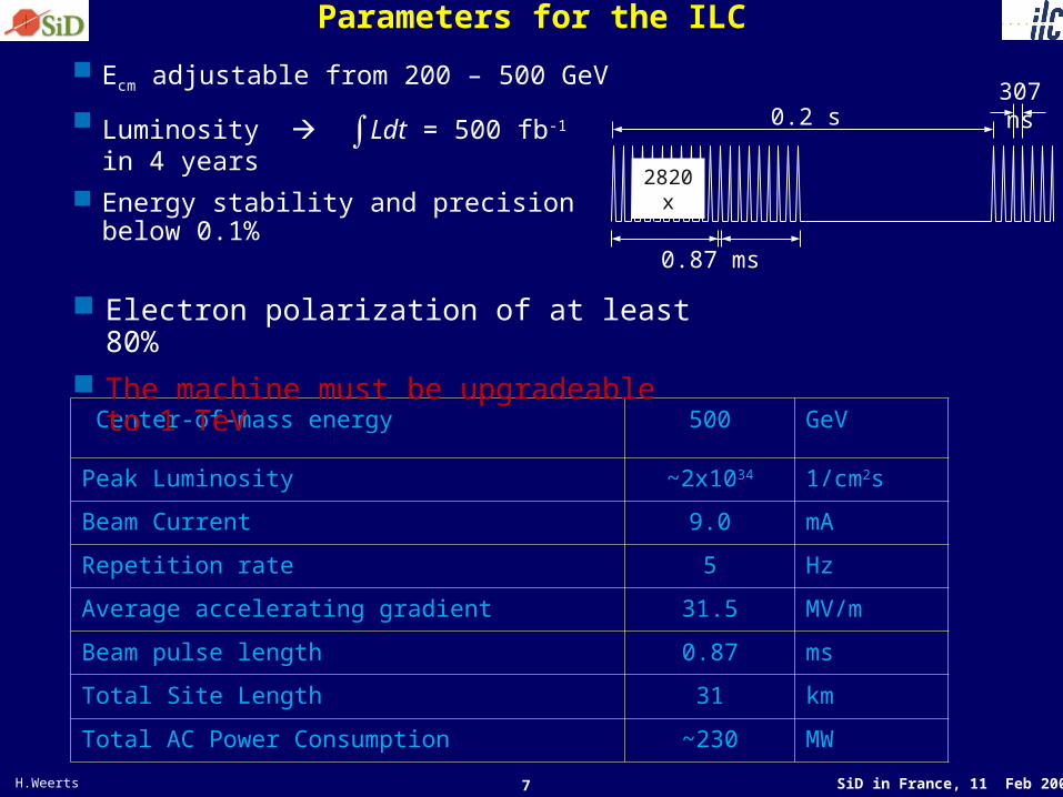
Parameters for the ILC
Ecm adjustable from 200 – 500 GeV
Luminosity ∫Ldt = 500 fb-1 in 4 years
Energy stability and precision below 0.1%
Center-of-mass energy 500 GeV
Peak Luminosity ~2x1034 1/cm2s
Beam Current 9.0 mA
Repetition rate 5 Hz
Average accelerating gradient 31.5 MV/m
Beam pulse length 0.87 ms
Total Site Length 31 km
Total AC Power Consumption ~230 MW
307 ns
2820x
0.2 s
0.87 ms
Electron polarization of at least 80% The machine must be upgradeable to 1
TeV

8 SiD in France, 11 Feb 2008 H.Weerts
Detector configuration: two at one IP
detectorB
may be accessible during run
accessible during run
Platform for electronic and services (~10*8*8m). Shielded (~0.5m of concrete) from five sides. Moves with detector. Also provide vibration isolation.
The concept is evolving and details being worked out
detectorA

9 SiD in France, 11 Feb 2008 H.Weerts
Reference Design Report complete
ExecutiveSummary
Physicsat theILC
AcceleratorDetectors
Next phase: Engineering Design report

10 SiD in France, 11 Feb 2008 H.Weerts
Modifications to GDE plan… 1Being proposed, not approved & negotiations ongoing From B.Barish talk at SiD & P5
TDP II - 2012
RF unit test – 3 CM + beam (STF) Complete technical design and R&D
needed for project proposal (some exceptions)
Documented design Complete and reliable cost roll up
Project plan developed by consensus Cryomodule Global Manufacturing
plan Siting Plan or Process
TDP I -- 2010 Technical risk reduction:
– Gradient • Results based on re-
processed cavities• Reduced number 540 390
(reduced US program) – Electron Cloud (CesrTA)
Cost risks (reductions) – Main Cost Drivers– Conventional Facilities (water,
etc)– Main Linac Technology
Technical progress ? (global design & US??)– Cryomodule baseline design
defined
Technical Design Phase = TDP; not EDR anymore

11 SiD in France, 11 Feb 2008 H.Weerts
Modifications to GDE plan… 2
TDP II 2012 what will not be done?
Detailed Engineering Design (final engineering, drawings, industry, etc) will follow before construction.
Global cryomodule industrial plant construction Other Unresolved Issues
– Positron Source ???– Damping Ring Design work?
From B.Barish talk at SiD & P5

12 SiD in France, 11 Feb 2008 H.Weerts
Evolution of ILC physics/detectors
Plans for near future:
WWS ( discussions ’06 & ’07) prepared way for this plan.
Fall 2007: call for Letters of Intent(LOI) for detectors
Next 3-4 years; keep pace with accelerator
Continue & conclude the vigorous, worldwide detector R&D partly independent of any concepts.
Identify the ILC Research Director (RD).Research Director identified/accepted: S. Yamada ( Tokyo Univ.)
RD expected
to:
April 2009: Letters of Intent completed
“Validate “ submitted LOI’s and therefore detector concepts. Some uncertainty here….
Any other steps depend on RD……..
Challenge: Produce LOI’s in ~ >one year
(Coupled to the plan for the machine & revised)
13 SiD in France, 11 Feb 2008 H.Weerts
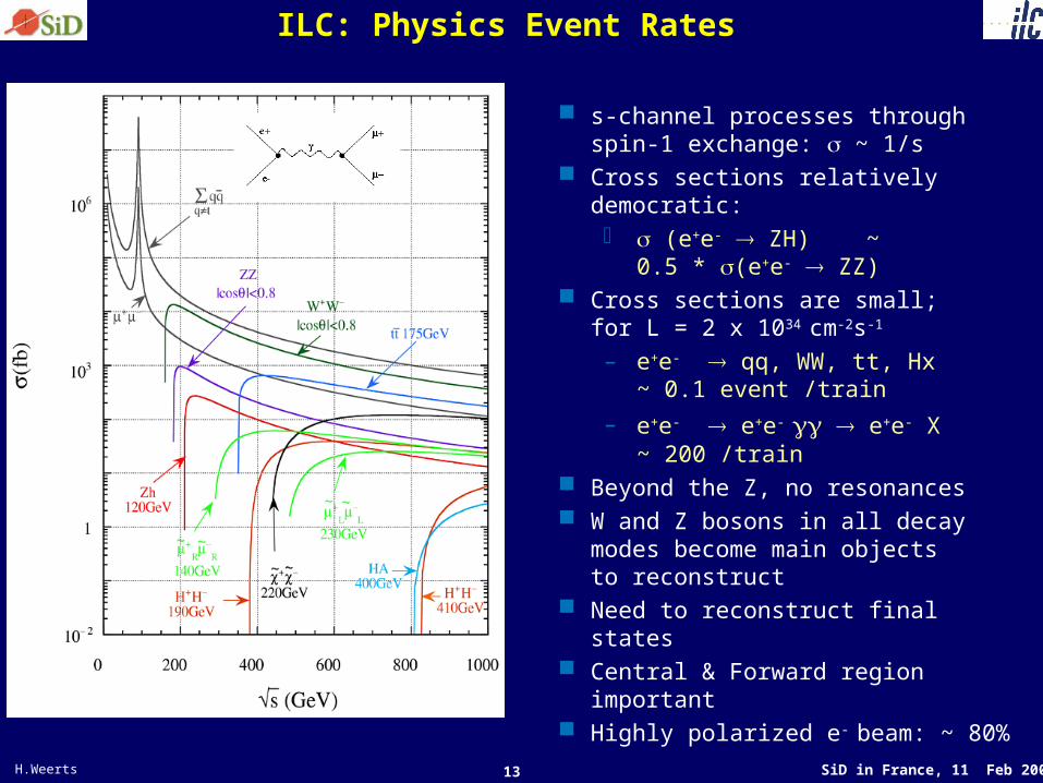
ILC: Physics Event Rates
s-channel processes through spin-1 exchange: ~ 1/s
Cross sections relatively democratic: (e+e- ZH) ~
0.5 * (e+e- ZZ) Cross sections are small;
for L = 2 x 1034 cm-2s-1
– e+e- qq, WW, tt, Hx ~ 0.1 event /train
– e+e- e+e- e+e- X ~ 200 /train
Beyond the Z, no resonances W and Z bosons in all decay
modes become main objects to reconstruct
Need to reconstruct final states Central & Forward region important Highly polarized e- beam: ~ 80%

14 SiD in France, 11 Feb 2008 H.Weerts
What should ILC detector be able to do ?
Identify ALL of the constituents that we know & can be produced in ILC collisions & precisely measure their properties.
u,d,s jets; no IDc, b jets with IDt final states; jets + W’s’s: missing energy; no IDe, : yes through decays ID & measuregluon jets, no IDW,Z leptonic & hadronic
Use this to measure/identify the NEW physics
( reconstruct the complete final state)

15 SiD in France, 11 Feb 2008 H.Weerts
Some Detector Design Criteria
Requirement for ILC
Impact parameter resolution
Momentum resolution
Jet energy resolution goal
Detector implications: – Calorimeter granularity – Pixel size – Material budget, central – Material budget, forward
Compared to best performance to date
Need factor 3 better than SLD
Need factor 10 (3) better than LEP (CMS)
Need factor 2 better than ZEUS
Detector implications: – Need factor ~200 better than LHC – Need factor ~20 smaller than LHC– Need factor ~10 less than LHC– Need factor ~ >100 less than LHC
)sin/(105 2/3 przr )sin/(337.7 2/3 pr
)(1051 15
GeV
pT
EEE %30
EE
E %60
LHC: staggering increase in scale, but modest extrapolation of performance
ILC: modest increase in scale, but significant push in performance
Observation:
%43 EE

16 SiD in France, 11 Feb 2008 H.Weerts
To be able to achieve the jet resolution can NOT simply use calorimeters as sampling devices.
)(
130.0
GeVEEE
Have to use “energy/particle flow (PFA)”. Technique has been used to improve jet resolution of existing calorimeters.
•use EM calorimeter ( EMCAL) to measure photons and electrons; •track charged hadrons from tracker through EMCAL, •identify energy deposition in hadron calorimeter (HCAL) with charged hadrons & replace deposition with measured momentum ( very good)
•When completed only E of neutral hadrons ( K’s, Lambda’s) is left in HCAL. Use HCAL as sampling cal for that.
Algorithm:
Require:
Imaging cal ( use as tracker = like bubble chamber), very fine transverse & longitudinal segmentationLarge dynamic range: MIP…. to …..showerExcellent EM resolution
Design Driver for any ILC detector
%43 EE

17 SiD in France, 11 Feb 2008 H.Weerts
Emerged picture after some maneuvering
LDC & GLD merged ILD Expect a concept based on strengths of both & TPC based
18 SiD in France, 11 Feb 2008 H.Weerts
How does the SiD Concept address the requirements ?
Here only outline. Detailed talks on most aspects.

19 SiD in France, 11 Feb 2008 H.Weerts
SiD Design Concept ( starting point)
“Jet Energy measurement =PFA” is the starting point in the SiD design
Premises at the basis of concept: – Particle flow calorimetry will deliver the
best possible performance– Si/W is the best approach for the ECAL
and digital calorimetry for HCAL– Limit calorimeter radius to constrain the
costs – Boost B-field to maintain BR2 – Use Si tracking system for best momentum
resolution and lowest mass – Use pixel Vertex detector for best
pattern recognition – Keep track of costs
Detector is viewed as single fully integrated system, not just a collection of different subdetectors
muon system
muon system
solenoid
HCAL
HC
AL
SiD
20 SiD in France, 11 Feb 2008 H.Weerts
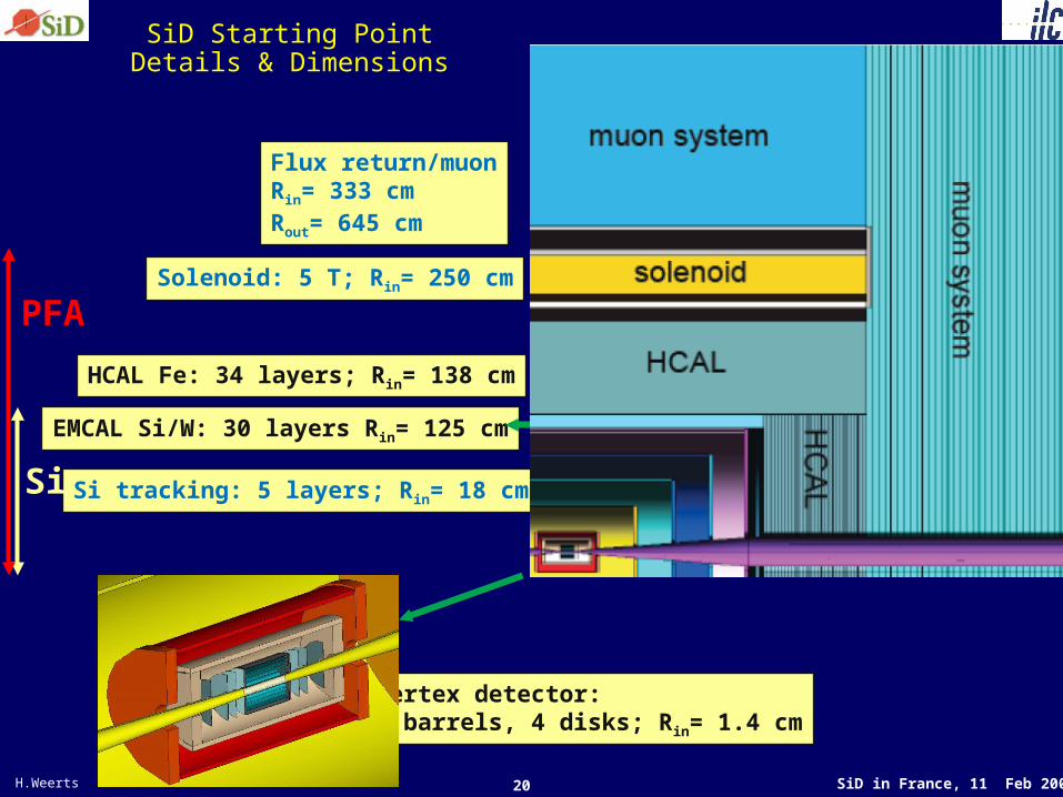
SiD Starting PointDetails & Dimensions
Vertex detector: 5 barrels, 4 disks; Rin= 1.4 cm
Si tracking: 5 layers; Rin= 18 cm
HCAL Fe: 34 layers; Rin= 138 cm
Solenoid: 5 T; Rin= 250 cm
EMCAL Si/W: 30 layers Rin= 125 cm
Flux return/muonRin= 333 cmRout= 645 cm
Si
PFA

21 SiD in France, 11 Feb 2008 H.Weerts
Vertexing and Tracking
Tracking system is conceived as an integrated, optimized detector– Vertex detection
• Inner central and forward pixel detector – Momentum measurement
• Outer central and forward tracking– Integration with calorimeter– Integration with very far forward system
Detector requirements (vertex)– Spacepoint resolution: < 4 m – Impact parameter resolution
– Smallest possible inner radius – Momentum resolution 5 10-5 (GeV-1)
– Transparency: ~0.1% X0 per layer
– Stand-alone tracking capability
mprzr )sin/(105 2/3
22 SiD in France, 11 Feb 2008 H.Weerts
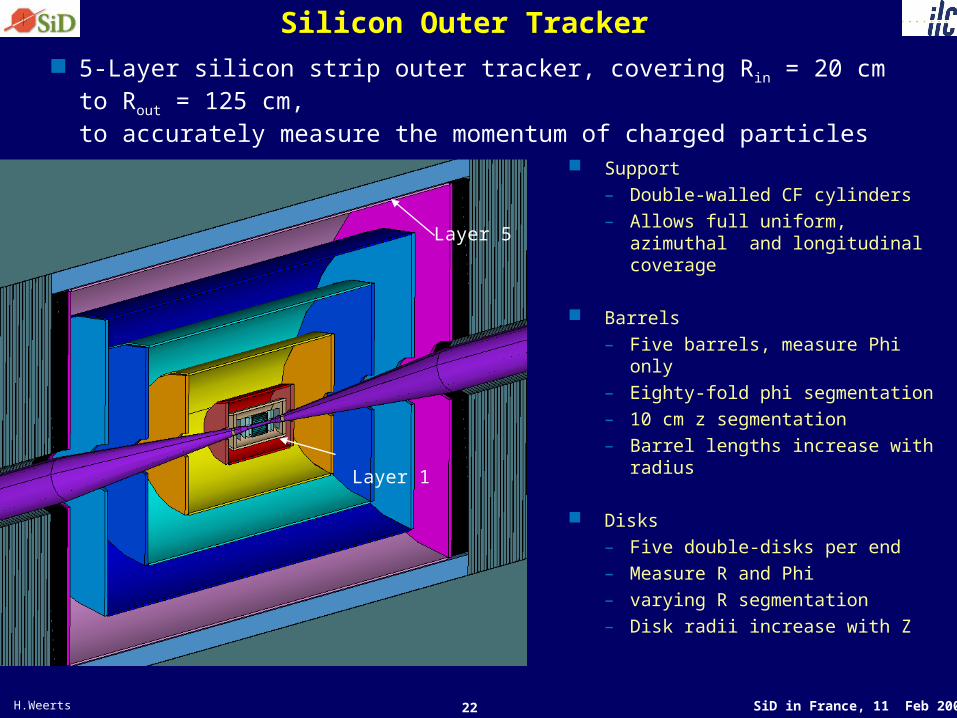
Silicon Outer Tracker
5-Layer silicon strip outer tracker, covering Rin = 20 cm to Rout = 125 cm, to accurately measure the momentum of charged particles
Support– Double-walled CF cylinders– Allows full uniform, azimuthal
and longitudinal coverage
Barrels– Five barrels, measure Phi only– Eighty-fold phi segmentation– 10 cm z segmentation – Barrel lengths increase with
radius
Disks– Five double-disks per end – Measure R and Phi– varying R segmentation– Disk radii increase with Z
Layer 1
Layer 5

23 SiD in France, 11 Feb 2008 H.Weerts
EM Calorimeter
Particle-Flow requires high transverse and longitudinal segmentation and dense medium
Choice: Si-W can provide very small transverse
segmentation and minimal effective Molière radius – Maintain Molière radius by minimizing the gap between the W
plates – Requires aggressive integration of electronics with mechanical
design
Absorber X0 [mm] RM [mm]
Iron 17.6 18.4
Copper 14.4 16.5
Tungsten 3.5 9.5
Lead 5.8 16.5
CAD overview
R 1.27 m
– 30 layers– ~ 1mm Si detector gaps
• Preserve RM(W)eff= 12 mm
– Pixel size ~ 4 x 4 mm2
– Energy resolution 15%/√E + 1%

24 SiD in France, 11 Feb 2008 H.Weerts
EM Calorimeter Statistics
– 20/10 layers, 2.5/5 mm W – ~ 1mm Si detector gaps– Tile with hexagonal 6” wafers– 4x4 mm2 pads– ~ 1300 m2 of Si
Readout with KPIX chip– 1024 channels, bump-bonded – 4-deep buffer (low occupancy) – Bunch crossing time stamp for
each hit– 64 ch. prototype in hand
CAD overview
R 1.27 m
-> +o

25 SiD in France, 11 Feb 2008 H.Weerts
Hadron Calorimetry
Role of hadron calorimeter in context of PFA is to measure neutrals and allow “tracking” i.e. matching of clusters to charged particles.– HCAL must operate with tracking and EM calorimeter as
integrated system Various Approaches
– Readout • Analog readout -- O(10) bit resolution • Digital readout -- 1-bit resolution (binary)
– Technolgoy• Active
– Resistive Plate Chambers, Gas Electron multipliers, MicroMegas– Scintillator
• Passive – Tungsten– Steel
– PFA Algorithms • Spatial separation• Hit density weighted • Gradient weighted
Example of a configuration

26 SiD in France, 11 Feb 2008 H.Weerts
Hadron Calorimeter
Current baseline configuration for SiD:– Digital calorimeter, inside the coil
• Ri = 139 cm, Ro =237 cm
– Thickness of 4(thin)
• 38 layers of 2.0cm steel • One cm gap for active medium
HV
Signal
Graphite
Resistive glass platesGas
Pick-up pads
All other options for HCAL are being pursued & explored.•Gas based: RPC, GEM and micromegas ( single bit /multibit)•Scintillator based ( R&D in CALICE)
HCAL: area of controversy, debate, choices to be made, depth ?, simulation, related to PFA
– Readout (one of choices) • RPC’s as active medium (ANL)• 1 x 1 cm2 pads

27 SiD in France, 11 Feb 2008 H.Weerts
Solenoid
Design calls for a solenoid with B(0,0) = 5T (not done previously)– Clear Bore Ø ~ 5 m; L = 5.4 m: Stored Energy ~ 1.2 GJ
• For comparison, CMS: 4 T, Ø = 6m, L = 13m: 2.7 GJ
Full feasibility study of design based on CMS conductor– Start with CMS conductor design, but increase winding layers from 4
to 6 • I(CMS)= 19500 A, I(SiD) = 18000 A; Peak Field (CMS) 4.6 T, (SiD)
5.8 • Net performance increase needed from conductor is modest
SiD Coil
HEP Detector Superconducting Solenoids
0
2
4
6
8
10
12
14
1 10 100 1000 10000Stored Energy [MJ]
Sto
red
En
erg
y/C
old
Ma
ss
[M
J/M
T]
Operating Forseen
CMS
TeslaSiD
GEM
SDC
Aleph
SDC Proto
H1
Delphi
D0
ISR Zeus
Venus
Topaz
AMY
Babar
Atlas
Cleo II
CDF
CMS 3.5
Studies on Dipole in Detector (DID) have been done/are being done as well

28 SiD in France, 11 Feb 2008 H.Weerts
Field simulation
Need small field beam entrance
Need expertise on conductor development and solenoid design.

29 SiD in France, 11 Feb 2008 H.Weerts
Muon System
Muon System Baseline Configuration – Octagon: 48 layers, 5 cm thick
steel absorber plates– Six planes of x, y or u, v
upstream of Fe flux return for xyz and direction of charged particles that enter muon system.
Muon ID studies – 12 RPC- instrumented gaps– ~1cm spatial resolution
Issues– Technology: RPC, Scin/SiPMs,
GEMS, Wire chambers– Is the muon system needed as
a tail catcher?– How many layers are needed
(0-23)? Use HCAL ?– Position resolution needed?
Muon
Coil
Hcal
trackers
Ecal
Eff. & Purity vs. Interaction Lengths
0
0.2
0.4
0.6
0.8
1
0 2 4 6 8Interaction Lengths
Eff
icie
nc
y/P
uri
ty
Eff
Purity
End of HCal

30 SiD in France, 11 Feb 2008 H.Weerts
Forward Detectors & Machine Detector Interface
Machine-Detector Interface at the ILC• (L,E,P) measurements: Luminosity, Energy, Polarization• Forward Region Detector layout ( lumcal, beamcal, gamcal)• Collimation and Backgrounds• IR Design and Detector Assembly• EMI (electro-magnetic interference) in IR
( includes forward calorimetry)
-0.25
-0.2
-0.15
-0.1
-0.05
0
0.05
0.1
0.15
0.2
0.25
0 0.5 1 1.5 2 2.5 3 3.5 4
8cm
20cm
113mrad
47mrad
QD0
MaskBcal
Ex. BeamPipe

31 SiD in France, 11 Feb 2008 H.Weerts
Engineering Group/EffortHave established a mechanical conceptual design group ( word “engineer” not allowed anymore in US.)
Looking at mechanical issues
Closed
One side open completely
Examples

32 SiD in France, 11 Feb 2008 H.Weerts
Summary: Technical Strengths
Generally: compact, highly integrated, hermetic detectorBunch by bunch timing resolution
Tracking: – VTD: small radius ( 5T helps)– Tracker: excellent dp/p; minimized material all cos()– Demonstrated pattern recognition– Solenoid: 5T (difficult but not unprecedented)
Calorimetry: imaging, hermetic
– ECAL: excellent segmentation=4x4 mm2, RMoliere=13mm
– HCAL: excellent segmentation: ~1x1 to 3x3 cm2
– Working on PFA performance Excellent ID: Instrumented flux return & imaging HCAL Simulation: Excellent simulation and reconstruction
software– Results shown only possible with that
(Leave to more expert talks)

33 SiD in France, 11 Feb 2008 H.Weerts
Summary: Technical weak points…
Judge for yourself after today’s presentations.

34 SiD in France, 11 Feb 2008 H.Weerts
Detector concept summary
A silicon-centric design offering– excellent vertexing and tracking precision– new potential in calorimetry– excellent muon identification
Complementary to other concepts Many opportunities for new effort and expertise. Tools and organization in place to support efficient
development and to get started. Great opportunity to explore ILC detector/physics. Open to new ideas, collaborators, increased
internationalization

35 SiD in France, 11 Feb 2008 H.Weerts
THE END
36 SiD in France, 11 Feb 2008 H.Weerts
Backup slides

37 SiD in France, 11 Feb 2008 H.Weerts
Summary
It is a great time to get involved in SiD Many interesting projects that can use contributions Challenging to work on new detector More information can be found in the SiD talks at
conferences & workshops Getting started is easy:
1. Identify an area in SiD where you would like to contribute2. Talk with SiD leadership about your interests and SiD
needs3. Start attending meetings and begin contributing to SiD
See the SiD web page for links to further information:
http://silicondetector.org
38 SiD in France, 11 Feb 2008 H.Weerts
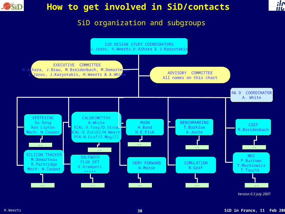
How to get involved in SiD/contacts
SiD DESIGN STUDY COORDINATORSJ.Jaros, H.Weerts,H.Aihara & J.Karyotakis
SILICON TRACKERM.DemarteauR.Partridge
Mech: W.Cooper
--
EXECUTIVE COMMITTEEH.Aihara, J.Brau, M.Breidenbach, M.Demarteau,
J.Jaros, J.Karyotakis, H.Weerts & A.White
SOLENOIDFLUX RET
K.Krempetz+++++
--
VERY FORWARDW.Morse
--
SIMULATIONN.Graf
--
MDIP.Burrows
T.MarkiewiczT.Tauchi
--
VERTEXINGSu Dong
Ron LiptonMech: W.Cooper
--
CALORIMETERSA.White
ECAL:R.Frey/D.StromHCAL:V.Zutshi/H.Weerts
PFA:N.Graf/S.Magill
--
MUONH.BandH.E.Fisk
--
BENCHMARKINGT.Barklow
A.Juste
--
COSTM.Breidenbach
--
R& D COORDINATORA. White
ADVISORY COMMITTEEAll names on this chart
SiD organization and subgroups
Version 0.3 July 2007
39 SiD in France, 11 Feb 2008 H.Weerts
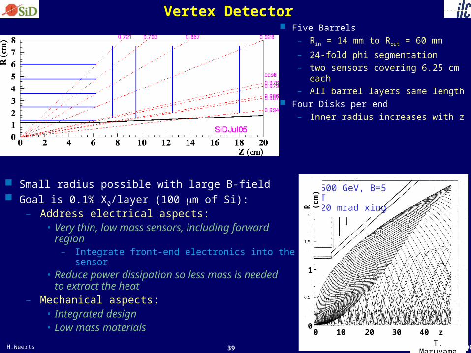
Vertex Detector
Small radius possible with large B-field Goal is 0.1% X0/layer (100 m of Si):
– Address electrical aspects: • Very thin, low mass sensors, including
forward region
– Integrate front-end electronics into the sensor • Reduce power dissipation so less mass is
needed to extract the heat
– Mechanical aspects: • Integrated design • Low mass materials
Five Barrels
– Rin = 14 mm to Rout = 60 mm
– 24-fold phi segmentation– two sensors covering 6.25
cm each
– All barrel layers same length Four Disks per end
– Inner radius increases with z
500 GeV, B=5 T20 mrad xing500 GeV, B=5 T20 mrad xing
00
1
10 20 30 z (cm)T. Maruyama
40
R (
cm
)

40 SiD in France, 11 Feb 2008 H.Weerts
Vertex Detector Sensors: The Challenge
Beam structure
What readout speed is needed ? – Inner layer 1.6 MPixel sensors; Background hits
significantly in excess of 1/mm2 will give pattern recognition problems
• Once per bunch = 300ns per frame : too fast• Once per train ~100 hits/mm2 : too slow• 5 hits/mm2 => 50µs per frame: may be tolerable
307 ns
2820x
0.2 s
0.87 ms
Fast CCDs– Development well underway– Need to be fast (50 MHz)– Read out in the gaps
Many different developments – MAPS – FAPS– HAPS– SOI– 3D
For SiD: cumulative number of bunches to reach hit density of 1/mm2
• Layer 1: ~35 • Layer 2: ~250

41 SiD in France, 11 Feb 2008 H.Weerts
Tracker Design
Baseline configuration – Cylinders are tiled with 10x10cm2
modules with minimal support
– Material budget 0.8% X0/layer
– z-segmentation of 10 cm
– Active volume, Ri=0.218 m, Ro=1.233 m
– Maximum active length = 3.3 m– Single sided in barrel; R, in disks– Overlap in phi and z
– Nested support – Power/Readout mounted on
support rings
– Disks tiled with wedge detectors – Forward tracker configuration to
be optimized

42 SiD in France, 11 Feb 2008 H.Weerts
Si Sensor Module/Mechanics
Sensor Module Tiles TrackerCylinders, Endcaps
Kapton cables route signalsand power to endcap modules
Next steps: FEA and Prototyping

43 SiD in France, 11 Feb 2008 H.Weerts
Tracking Performance
Full simulation Vertex detector seeded pattern
recognition (3 hit combinations)
Event Sample– ttbar-events– √s = 500 GeV– background included
Black: VXD basedRed: VXD + tracker
)(
12
GeV
pp TT
)(GeVpT
EfficiencyCentral Resolution

44 SiD in France, 11 Feb 2008 H.Weerts
Calorimeter Tracking With a fine grained calorimeter, can do tracking with the
calorimeter
– Track from outside in: K0s and or long-lived SUSY particles,
reconstruct V’s– Capture events that tracker pattern recognition doesn’t find
Layer 2

45 SiD in France, 11 Feb 2008 H.Weerts
ILC Physics Characteristics
Cross sections above Z-resonance are very small s-channel processes through spin-1 exchange Highly polarized e- beam: ~ 80%
Hermetic detectors with uniform strengths – Importance of forward regions – b/c tagging and quark identification
– Measurements of spin, charge, mass, … Analyzing power of
– Scan in center of mass energy – Various unique Asymmetries
• Forward-backward asymmetry
• Left-Right Asymmetry • Largest effects for b-quarks
cos)(2)cos1()1(
8
3
cos2
feeeetot
ff
ff
d
dAPAAP
AfVf
AfVff gg
gg22
2
A 94.0bA 67.0cA 15.0lA
HZ qqllMH = 120 GeV
Errors correspond to 20 fb-1
Identify all final state objects

46 SiD in France, 11 Feb 2008 H.Weerts
Momentum resolution
Benchmark measurement is the measurement of the Higgs recoil mass in the channel e+e- → ZH– Higgs recoil mass resolution improves until
∆p/p2 ~ 5 x 10⁻⁵ – Sensitivity to invisible Higgs decays, and purity
of recoil-tagged Higgs sample, improve accordingly.
• Example: – s = 300 GeV– 500 fb-1
– beam energy spread of 0.1%
• Goal:– Mll < 0.1x
Illustrates need for superb momentum resolution in tracker

47 SiD in France, 11 Feb 2008 H.Weerts
ILC requires precise measurement for jet energy/di-jet mass
At LEP, ALEPH got a jet energy resolution of ~60%/sqrt(E)– Achieved with Particle Flow Algorithm (Energy Flow, at the time) on a
detector not optimized for PFA This is not good enough for ILC physics program, we need to do a lot better!

48 SiD in France, 11 Feb 2008 H.Weerts
ILC goal for jet energy resolution
ILC goal: distinguish W, Z by their di-jet invariant mass– Well known expression: jet energy resolution ~ 30%/sqrt(E)– More realistic goal (from physics requirement): flat 3-4% resolution
– The two are about equivalent for Mjj ~100 GeV produced at rest Most promising approach: Particle Flow Algorithm (PFA) + detector
optimized for PFA ( a whole new approach!)
60%/sqrt(E)
Distinguish WWfrom ZZ, using Mjj
30%/sqrt(E)
e+e- → ZH → qqbb @ 350GeV, 500fb-1Mjj of two b-jets for different jet energy resolution.
→ 40% luminosity gain
49 SiD in France, 11 Feb 2008 H.Weerts
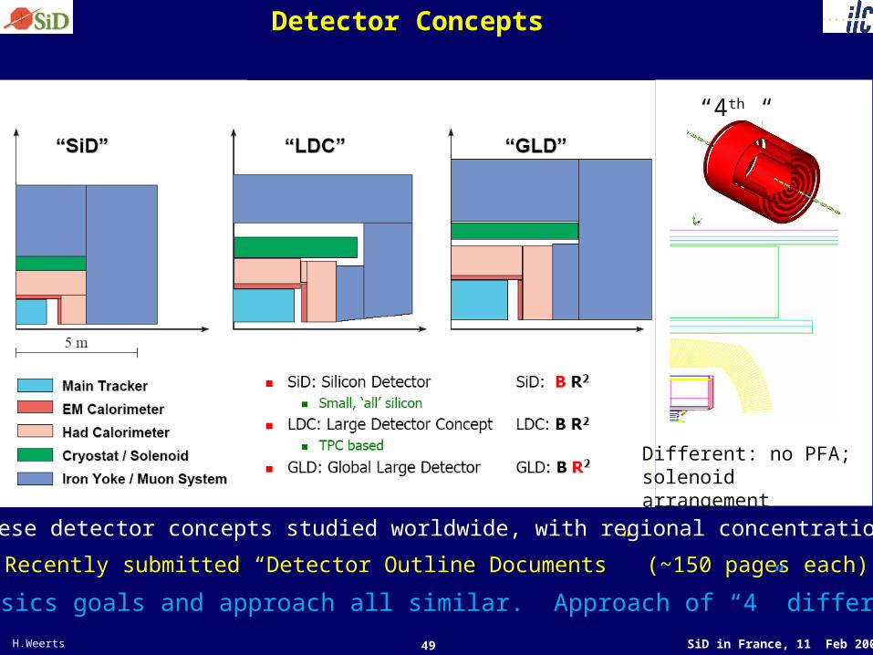
Detector Concepts
“4th “
Different: no PFA; solenoid arrangement
These detector concepts studied worldwide, with regional concentrations
Recently submitted “Detector Outline Documents” (~150 pages each)
Physics goals and approach all similar. Approach of “4” different

50 SiD in France, 11 Feb 2008 H.Weerts
Current detector concepts being pursued

51 SiD in France, 11 Feb 2008 H.Weerts
Event DisplayEvent display to illustrate granularity
More detail
-> +o
Very fine detail

52 SiD in France, 11 Feb 2008 H.Weerts
SiD PFA performance: e+e-qqbar(uds) @ 91GeV
All events, no cut
Mean 88.43 GeVRMS 5.718 GeVRMS90 3.600 GeV[42.6 %/sqrt(E) or σEjet /Ejet=6.4 %]
Barrel events (cos(theta[Q]) < 1/sqrt(2))
Mean 89.10 GeVRMS 4.646 GeVRMS90 3.283 GeV[34.7 %/sqrt(E) or σEjet /Ejet=5.2 %]
Still not quite 30%/sqrt(E) or 3-4% yet, but close now
(rms90: rms of central 90% of events)
53 SiD in France, 11 Feb 2008 H.Weerts
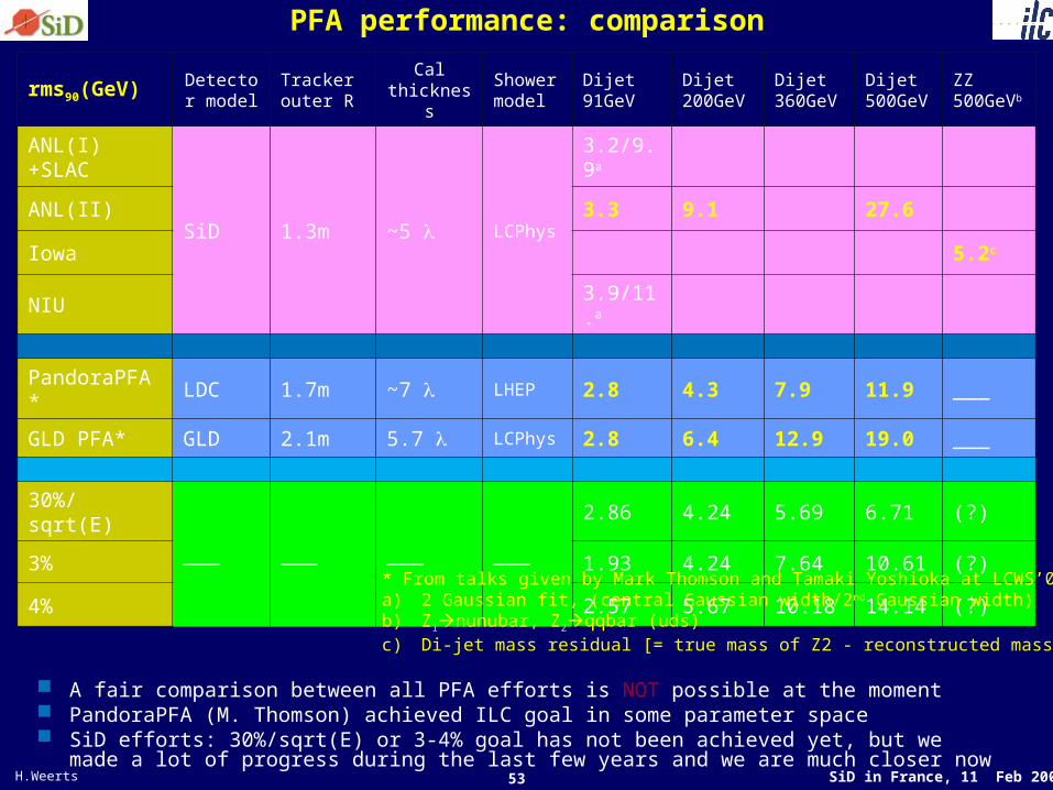
PFA performance: comparison
rms90(GeV) Detector model
Tracker outer R
Cal thickness
Shower model
Dijet 91GeV
Dijet 200GeV
Dijet 360GeV
Dijet 500GeV
ZZ 500GeVb
ANL(I)+SLAC
SiD 1.3m ~5 LCPhys
3.2/9.9a
ANL(II) 3.3 9.1 27.6
Iowa 5.2c
NIU3.9/11.a
PandoraPFA* LDC 1.7m ~7 LHEP 2.8 4.3 7.9 11.9 ___
GLD PFA* GLD 2.1m 5.7 LCPhys 2.8 6.4 12.9 19.0 ___
30%/sqrt(E)
___ ___ ___ ___
2.86 4.24 5.69 6.71 (?)
3% 1.93 4.24 7.64 10.61 (?)
4% 2.57 5.67 10.18 14.14 (?)
* From talks given by Mark Thomson and Tamaki Yoshioka at LCWS’07a) 2 Gaussian fit, (central Gaussian width/2nd Gaussian width)b) Z1nunubar, Z2qqbar (uds)c) Di-jet mass residual [= true mass of Z2 - reconstructed mass of Z2]
A fair comparison between all PFA efforts is NOT possible at the moment PandoraPFA (M. Thomson) achieved ILC goal in some parameter space SiD efforts: 30%/sqrt(E) or 3-4% goal has not been achieved yet, but we made a lot of
progress during the last few years and we are much closer now

54 SiD in France, 11 Feb 2008 H.Weerts
Technically Driven Timeline
August
BCD
All regions ~ 5 yrs
Construction Startup
Siting Plan being Developed
2006 2010 2014 2018
RDR EDRBeginConst
EndConst
EngineerDesign
Site Prep
Site Select
R & D -- Industrialization
Gradient
e-CloudCryomoduleFull Production
System Tests
& XFEL
Detector Install
Detector Construct
Pre-Operations
ILC

55 SiD in France, 11 Feb 2008 H.Weerts
PFA performance: e+e- ZZ @ 500GeV Z1 nunubar, Z2 qqbar (uds) Di-jet mass residual = (true mass of Z2 - reconstructed mass of Z2)
– μ90: mean of central 90% events– rms90: rms of central 90% events
SiD SS/Scin HCAL
SiD W/Scin HCAL SiD W/RPC HCAL
SiD SS/RPC HCAL

56 SiD in France, 11 Feb 2008 H.Weerts
Difference in “energy frontier” experiments (ee)
Two main kind of machines:1)electron –positron ( e+e- annihilation) colliders2)proton-(anti)proton collider ( Tevatron, future
LHC)e+e- annihilation: Total energy of e+ and e- available as Ecms or s
Scan over resonancesMaximum achieved for Ecms =192 GeV
Very clean environment; precision physics
Energy range covered by e+e- colliders

57 SiD in France, 11 Feb 2008 H.Weerts
World Wide Study R&D Panel
The World Wide Study Organizing Committee has established the Detector R&D Panel to promote and coordinate detector R&D for the ILC. Worldwide activities at:– https://wiki.lepp.cornell.edu/wws/bin/view/Projects/WebHome
ILC detector R&D needs: funded & needed
Urgent R&D support levels over the next 3-5 years, by subdetector type. 'Established' levels are what people think they will get under current conditions, and 'total required' are what they need to establish proof-of-principle
for their project.

58 SiD in France, 11 Feb 2008 H.Weerts
Backgrounds
“At the ILC the initial state is well defined, compared to LHC, but….”
Backgrounds from the IP – Disrupted beams
• Extraction line losses– Beamstrahlung photons– e+e- - pairs
Backgrounds from the machine– Muon production at collimators– Synchrotron radiation – Neutrons from dumps,
extraction lines
s (GeV) Beam# e+e- per BX
Total Energy (TeV)
500Nomina
l 98 K 197
1000Nomina
l 174 K 1042
~ 20 cm
~ 12 m
59 SiD in France, 11 Feb 2008 H.Weerts
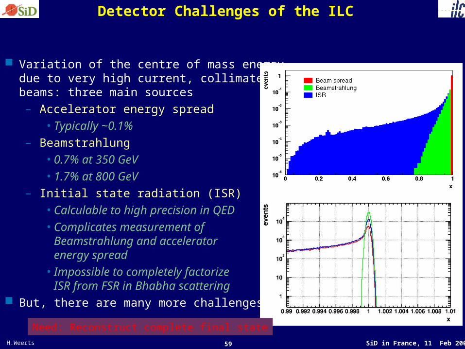
Detector Challenges of the ILC
Variation of the centre of mass energy, due to very high current, collimated beams: three main sources– Accelerator energy spread
• Typically ~0.1%– Beamstrahlung
• 0.7% at 350 GeV• 1.7% at 800 GeV
– Initial state radiation (ISR)• Calculable to high precision in QED• Complicates measurement of
Beamstrahlung and accelerator energy spread
• Impossible to completely factorize ISR from FSR in Bhabha scattering
But, there are many more challenges
Need: Reconstruct complete final state

60 SiD in France, 11 Feb 2008 H.Weerts
EM Calorimeter Layout
Tile W with hexagonal 6” wafers– ~ 1300 m2 of Si – 5x5 mm2 pads– Readout by single chip – 1024 channels, bump-bonded
Signals– Single MIP with S/N > 7– Dynamic range of 2500 MIPs– < 2000 e- noise
Power– < 40 mW/wafer through
power pulsing ! – Passive edge cooling
Readout with kPix chip– 4-deep buffer (low occupancy) – Bunch crossing time stamp for
each hit Testing
– Prototype chip in hand with 2x32 channels
– Prototype sensors in hand– Test beam foreseen in 2006

61 SiD in France, 11 Feb 2008 H.Weerts
Calorimetry
Goal is jet energy resolution of 30%/√E Current paradigm is that this can be achieved with Particle
Energy Flow A particle flow algorithm is a recipe to improve the jet energy
resolution by minimizing the contribution from the hadronic energy resolution by reducing the function of a hadron calorimeter to the measurement of neutrons and K0’s only
Particles in jetsFraction of energy
Measured withResolution [σ2]
Charged ~ 65 % Tracker Negligible
Photons ~ 25 % ECAL with 15%/√E 0.072 Ejet
Neutral Hadrons
~ 10 % ECAL + HCAL with 50%/√E
0.162 Ejet
– Measure charged particles in the tracking system
– Measure photons in the ECAL
– Measure neutral hadrons in the HCAL (+ ECAL) by subtracting calorimeter energy associated with charged hadrons
~20%/√E

62 SiD in France, 11 Feb 2008 H.Weerts
Why ILC detector R&D ?
bunch spacing 337 nsec
#bunch/train 2820
length of train 950 sec
#train/sec 5 Hz
train spacing 199 msec
crossing angle 0-20 mrad ( 25 for )
ILC
From a naïve perspective looks like simple problem
But there are other factors which require better performance…..
Extrapolating from LHC

63 SiD in France, 11 Feb 2008 H.Weerts
Vertex detector
A lot of effort going into mechanical/electrical design considerations for vertex detector and tracking system
Example of current thinking