, THE CAVE AUTOMATIC VIRTUAL ENVIRONMENT: CHARACTERISTICS ... · , THE CAVE" AUTOMATIC VIRTUAL...
19
, THE CAVE" AUTOMATIC VIRTUAL ENVIRONMENT: CHARACTERISTICS AND APPLICATIONS l Robert V. Kenyon Electronic Visualization Lab University of Illinois at Chicago Department of Electrical Engineering and Computer Science Chicago, IL INTRODUCTION Virtual reality may best be defined as the wide-field presentation of computer-generated, multi- sensory information that tracks a user in real time. In addition to the more well-known modes of virtual reality - head-mounted displays and boom-mounted displays - the Electronic Visualization Laboratory at the University of Illinois at Chicago recently introduced a third mode: a room constructed from large screens on which the graphics are projected on to three walls and the floor. The CAVE is a multi-person, room-sized, high-resolution, 3D video and audio environment. Graphics are rear projected in stereo onto three walls and the floor, and viewed with stereo glasses (Ref. 1). As a viewer wearing a location sensor moves within its display boundaries, the correct perspective and stereo projections of the environment are updated, and the image moves with and surrounds the viewer. The other viewers in the CAVE are like passengers in a bus, along for the ride! "CAVE," the name selected for the virtual reality theater, is both a recursive acronym (Cave Automatic Virtual Environment) and a reference to "The Simile of the Cave" found in Plato's "Republic," in which the philosopher explores the ideas of perception, reality, and illusion. Plato used the analogy of a person facing the back of a cave alive with shadows that are his/her only basis for ideas of what real objects are. Rather than having evolved from video games or flight simulation, the CAVE has its motivation rooted in scientific visualization and the SIGGRAPH 92 Showcase effort. The CAVE was designed to be a useful tool for scientific visualization. The Showcase event was an experiment; the Showcase chair, James E. George, and the Showcase committee advocated an environment for computational scientists to interactively present their research at a major professional conference in a one-to-many format on high- end workstations attached to large projection screens. The CAVE was developed as a "virtual reality theater" with scientific content and projection that met the criteria of Showcase. CAVE is a registered trademark of the Regents of the University of Illinois. ' This research was supported by NSF Grant number IRI-9213822. 150 https://ntrs.nasa.gov/search.jsp?R=19960026482 2020-02-13T20:23:09+00:00Z
Transcript of , THE CAVE AUTOMATIC VIRTUAL ENVIRONMENT: CHARACTERISTICS ... · , THE CAVE" AUTOMATIC VIRTUAL...
, THE CAVE" AUTOMATIC VIRTUAL ENVIRONMENT: CHARACTERISTICS AND
APPLICATIONS l
Robert V. Kenyon
Electronic Visualization Lab
University of Illinois at Chicago
Department of Electrical Engineering and Computer Science
Chicago, IL
INTRODUCTION
Virtual reality may best be defined as the wide-field presentation of computer-generated, multi-sensory information that tracks a user in real time. In addition to the more well-known modes of virtual
reality - head-mounted displays and boom-mounted displays - the Electronic Visualization Laboratory at
the University of Illinois at Chicago recently introduced a third mode: a room constructed from large
screens on which the graphics are projected on to three walls and the floor.
The CAVE is a multi-person, room-sized, high-resolution, 3D video and audio environment.
Graphics are rear projected in stereo onto three walls and the floor, and viewed with stereo glasses
(Ref. 1). As a viewer wearing a location sensor moves within its display boundaries, the correct
perspective and stereo projections of the environment are updated, and the image moves with and
surrounds the viewer. The other viewers in the CAVE are like passengers in a bus, along for the ride!
"CAVE," the name selected for the virtual reality theater, is both a recursive acronym (Cave
Automatic Virtual Environment) and a reference to "The Simile of the Cave" found in Plato's "Republic,"
in which the philosopher explores the ideas of perception, reality, and illusion. Plato used the analogy of a
person facing the back of a cave alive with shadows that are his/her only basis for ideas of what real
objects are.
Rather than having evolved from video games or flight simulation, the CAVE has its motivation
rooted in scientific visualization and the SIGGRAPH 92 Showcase effort. The CAVE was designed to be
a useful tool for scientific visualization. The Showcase event was an experiment; the Showcase chair,
James E. George, and the Showcase committee advocated an environment for computational scientists to
interactively present their research at a major professional conference in a one-to-many format on high-
end workstations attached to large projection screens. The CAVE was developed as a "virtual reality
theater" with scientific content and projection that met the criteria of Showcase.
CAVE is a registered trademark of the Regents of the University of Illinois.' This research was supported by NSF Grant number IRI-9213822.
150
https://ntrs.nasa.gov/search.jsp?R=19960026482 2020-02-13T20:23:09+00:00Z
GENERAL CHARACTERISTICS
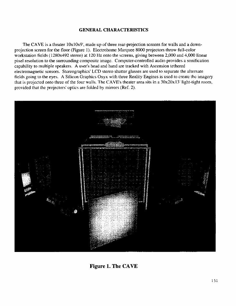
The CAVE is a theater 10x 10x9', made up of three rear-projection screens for walls and a down-
projection screen for the floor (Figure 1). Electrohome Marquee 8000 projectors throw full-color
workstation fields (1280x492 stereo) at 120 Hz onto the screens, giving between 2,000 and 4,000 linear
pixel resolution to the surrounding composite image. Computer-controlled audio provides a sonification
capability to multiple speakers. A user's head and hand are tracked with Ascension tethered
electromagnetic sensors. Stereographics' LCD stereo shutter glasses are used to separate the alternate
fields going to the eyes. A Silicon Graphics Onyx with three Reality Engines is used to create the imagery
that is projected onto three of the four walls. The CAVE's theater area sits in a 30x20x 13' light-tight room,
provided that the projectors' optics are folded by mirrors (Ref. 2).
Figure 1. The CAVE
151
CAVE CHARACTERISTICS
Over the past two years, as we considered building the CAVE, there were several inherent problems
with head-mounted virtual-reality technology to which we gave a great deal of thought:
a. Simplistic real-time walk-around imagery
b. Unacceptable resolution (the popular head-mounted displays offer resolution that is twice
as bad as being legally blind)
c. Difficulty of sharing experiences between two or more people
d. Primitive color and lighting models
e. No capability for successive refinement of images
f. Too sensitive to rapid head movement
g. No easy integration with real control devices
h. Disorientation a common problem
i. Poor multi-sensory integration, including sound and touch
The CAVE has the current capabilities and engineering characteristics:
Multi-person Virtual Environment
Back projection onto 10'xl0'x9' roomWide field-of-view
High resolution color images
Inside-out surround 3-D video presentation
Off axis stereo projectionHead and hand-tracked user interaction
Co-existing real and virtual objects3-D Audio
SGI Onyx with 3 Reality Engine 2s=_ 2 adjoining walls and the floor
No force or tactile feedback (yet)
Expensive
Figure 2
152
VIDEO SYSTEM
The CAVE has an inside-out viewing paradigm where the design is such that the observer is inside
,king out as opposed to the outside looking in (Ref. 3). The CAVE uses "window" projection where the
_jection plane and the center of projection relative to the plane are specified for each eye, thus creating
off-axis perspective projection (Ref. 4). The correct perspective and stereo projections are based on
ues returned by the Ascension position sensor attached to the Stereographics Crystal Eyes stereo shutter
sses. Each screen updates at 96 Hz or 120 Hz with a resolution of 1025x768 or 1280x492 pixels per
een, respectively. Two off-axis stereo projections are displayed on each wall. To give the illusion of
), the viewer wears stereo shutter glasses that enable a different image to be displayed to each eye by
ichronizing the rate of alternating shutter openings to the screen update rate. When generating a stereo
age, the screen update rate is effectively cut in half due to the necessity of displaying two images for
•.3-D image. Thus, with a 96 Hz screen update rate, the total image has a maximum screen update rate
_8 Hz. The CAVE has a panoramic view that varies from 90 ° to greater than 180 ° depending upon the
tance of the viewer from the projection screens. The direct viewing field of view is about 100 ° and is a
ction of the frame design for the stereo glasses.
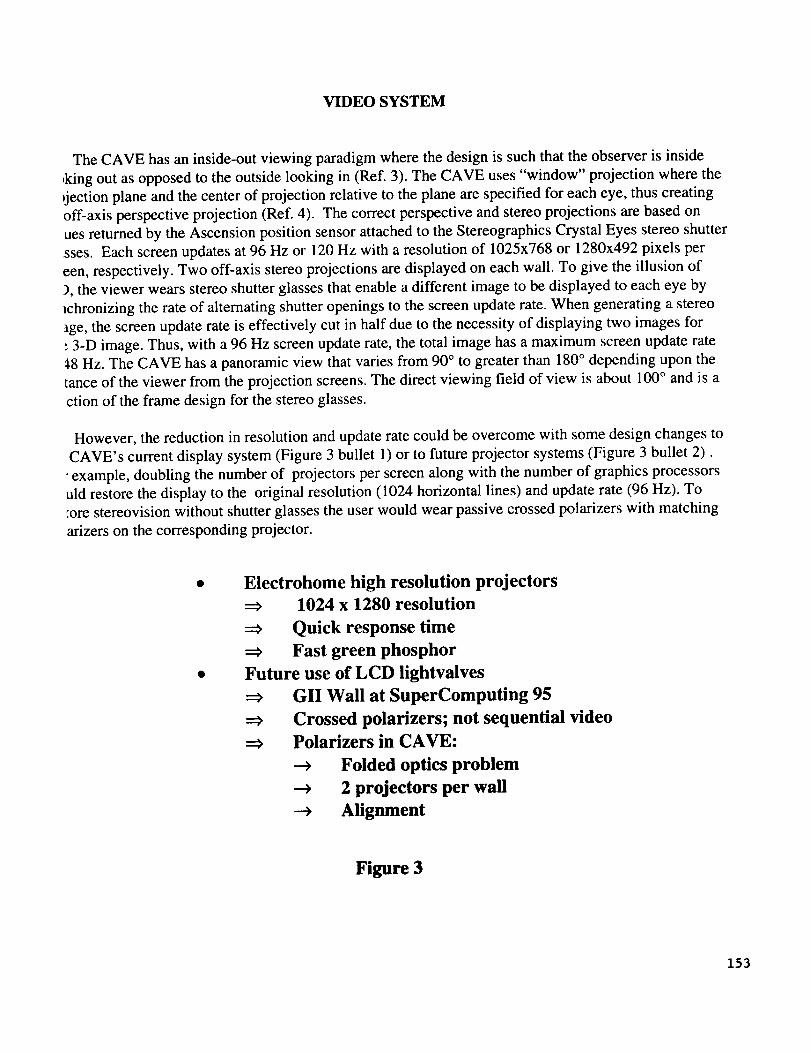
However, the reduction in resolution and update rate could be overcome with some design changes to
CAVE's current display system (Figure 3 bullet 1) or to future projector systems (Figure 3 bullet 2).
• example, doubling the number of projectors per screen along with the number of graphics processors
uld restore the display to the original resolution (1024 horizontal lines) and update rate (96 Hz). To
tore stereovision without shutter glasses the user would wear passive crossed polarizers with matching
arizers on the corresponding projector.
Electrohome high resolution projectors
1024 x 1280 resolution
Quick response time
Fast green phosphor
Future use of LCD lightvalves
GII Wall at SuperComputing 95
Crossed polarizers; not sequential video
Polarizers in CAVE:
--_ Folded optics problem
-_ 2 projectors per wall
-_ Alignment
Figure 3
153
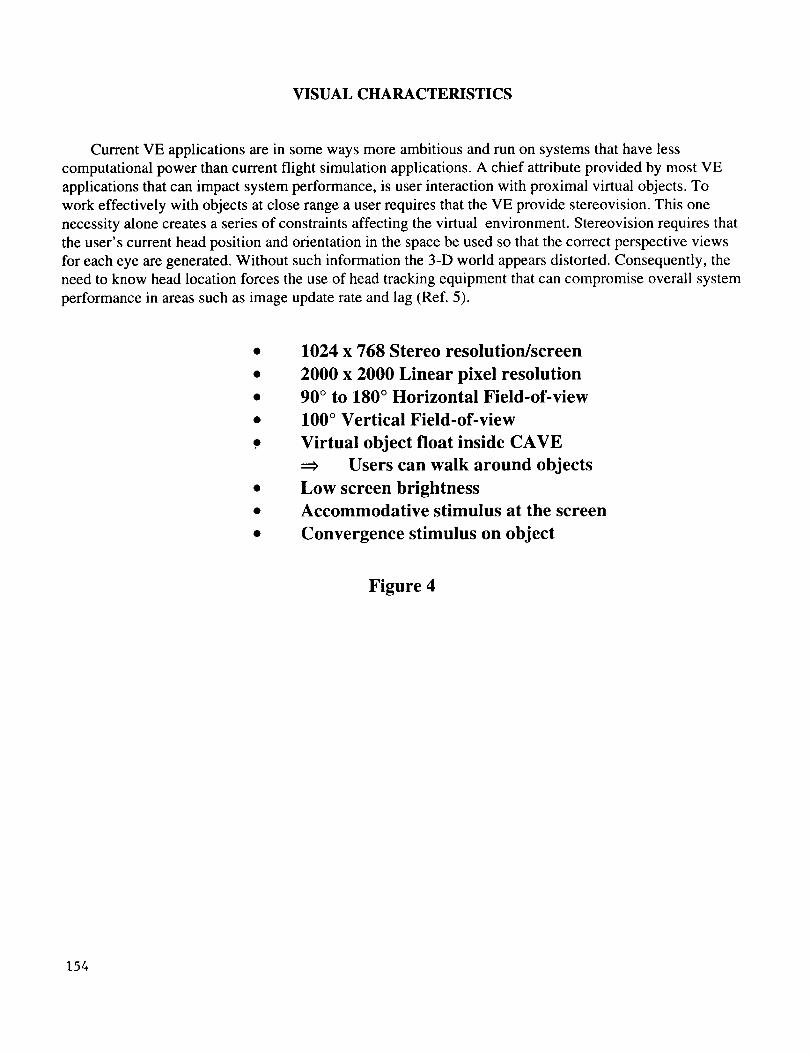
VISUAL CHARACTERISTICS
Current VE applications are in some ways more ambitious and run on systems that have less
computational power than current flight simulation applications. A chief attribute provided by most VE
applications that can impact system performance, is user interaction with proximal virtual objects. To
work effectively with objects at close range a user requires that the VE provide stereovision. This one
necessity alone creates a series of constraints affecting the virtual environment. Stereovision requires that
the user's current head position and orientation in the space be used so that the correct perspective views
for each eye are generated. Without such information the 3-D world appears distorted. Consequently, the
need to know head location forces the use of head tracking equipment that can compromise overall system
performance in areas such as image update rate and lag (Ref. 5).
1024 x 768 Stereo resolution/screen
2000 x 2000 Linear pixel resolution
90 ° to 180 ° Horizontal Field-of-view
100 ° Vertical Field-of-view
Virtual object float inside CAVE
Users can walk around objects
Low screen brightness
Accommodative stimulus at the screen
Convergence stimulus on object
Figure 4
154
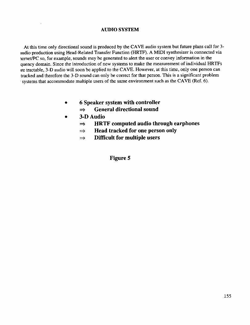
AUDIO SYSTEM
At this time only directional sound is produced by the CAVE audio system but future plans call for 3-
audio production using Head-Related Transfer Function (HRTF). A MIDI synthesizer is connected via
lernet/PC so, for example, sounds may be generated to alert the user or convey information in the
quency domain. Since the introduction of new systems to make the measurement of individual HRTFs
_re tractable, 3-D audio will soon be applied to the CAVE. However, at this time, only one person can
tracked and therefore the 3-D sound can only be correct for that person. This is a significant problem
• systems that accommodate multiple users of the same environment such as the CAVE (Ref. 6).
6 Speaker system with controllerGeneral directional sound
3-D Audio
HRTF computed audio through earphones
Head tracked for one person only
Difficult for multiple users
Figure 5
155
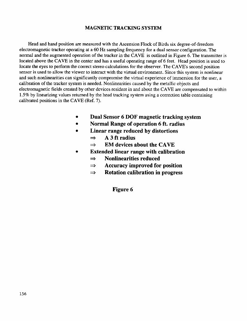
MAGNETIC TRACKING SYSTEM
Head and hand position are measured with the Ascension Flock of Birds six degree-of-freedom
electromagnetic tracker operating at a 60 Hz sampling frequency for a dual sensor configuration. The
normal and the augmented operation of the tracker in the CAVE is outlined in Figure 6. The transmitter is
located above the CAVE in the center and has a useful operating range of 6 feet. Head position is used to
locate the eyes to perform the correct stereo calculations for the observer. The CAVE's second position
sensor is used to allow the viewer to interact with the virtual environment. Since this system is nonlinear
and such nonlinearities can significantly compromise the virtual experience of immersion for the user, a
calibration of the tracker system is needed. Nonlinearities caused by the metallic objects and
electromagnetic fields created by other devices resident in and about the CAVE are compensated to within
1.5% by linearizing values returned by the head tracking system using a correction table containing
calibrated positions in the CAVE (Ref. 7).
Dual Sensor 6 DOF magnetic tracking system
Normal Range of operation 6 ft. radius
Linear range reduced by distortionsA 3 ft radius
EM devices about the CAVE
Extended linear range with calibrationNonlinearities reduced
Accuracy improved for position
Rotation calibration in progress
Figure 6
156
CA VE CALIBRATION
The goal of the calibration procedure (outlined in Figure 7) is to correct for static position errors in
the magnetic tracker. Metal structures near the tracker distort the magnetic field, so the CAVE screenframe is made of austenetic stainless steel which is non-magnetic and has a low conductivity. However,
other components needed for the CAVE to function such as projectors and mirrors significantly distort the
field. These distortions produce errors in the position component of the 6-degree-of-freedom magnetic
tracker. By comparing the output with a custom-built ultrasonic measuring system to the position reported
by the magnetic tracker, a look-up table is created from the collected difference data and is used to
interpolate for corrected values. The error of the resulting corrected magnetic tracker position is measured
to be less than 5% over the calibrated range
CAVE filled with array of cubic calibration locations
Magnetic/Sonic Calibration probe
Probe placed inside cube
X,Y,Z location recorded by sonic system
Sonic data correlated to simultaneous Magnetic data
Calibration array generated and data interpolated from
lookup table
Figure 7
157
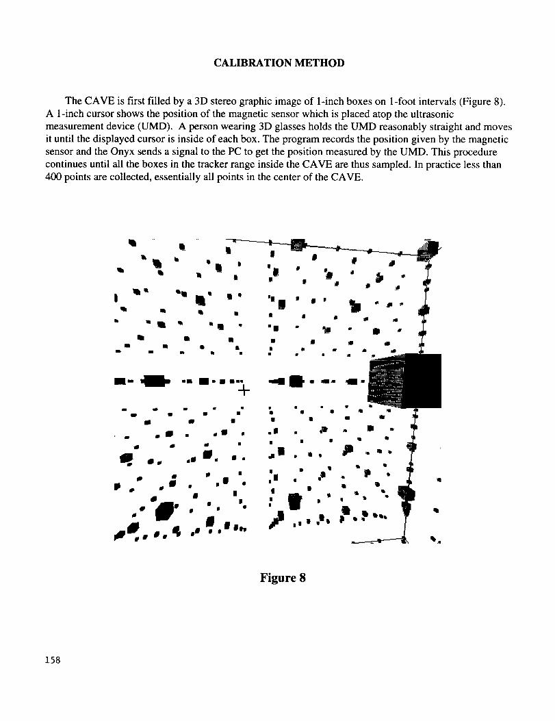
CALIBRATION METHOD
The CAVE is first filled by a 3D stereo graphic image of 1-inch boxes on 1-foot intervals (Figure 8).
A 1-inch cursor shows the position of the magnetic sensor which is placed atop the ultrasonic
measurement device (UMD). A person wearing 3D glasses holds the UMD reasonably straight and moves
it until the displayed cursor is inside of each box. The program records the position given by the magnetic
sensor and the Onyx sends a signal to the PC to get the position measured by the UMD. This procedure
continues until all the boxes in the tracker range inside the CAVE are thus sampled. In practice less than
400 points are collected, essentially all points in the center of the CAVE.
I" _ -m m-.--, _l" "" a-+
I
Figure 8
158
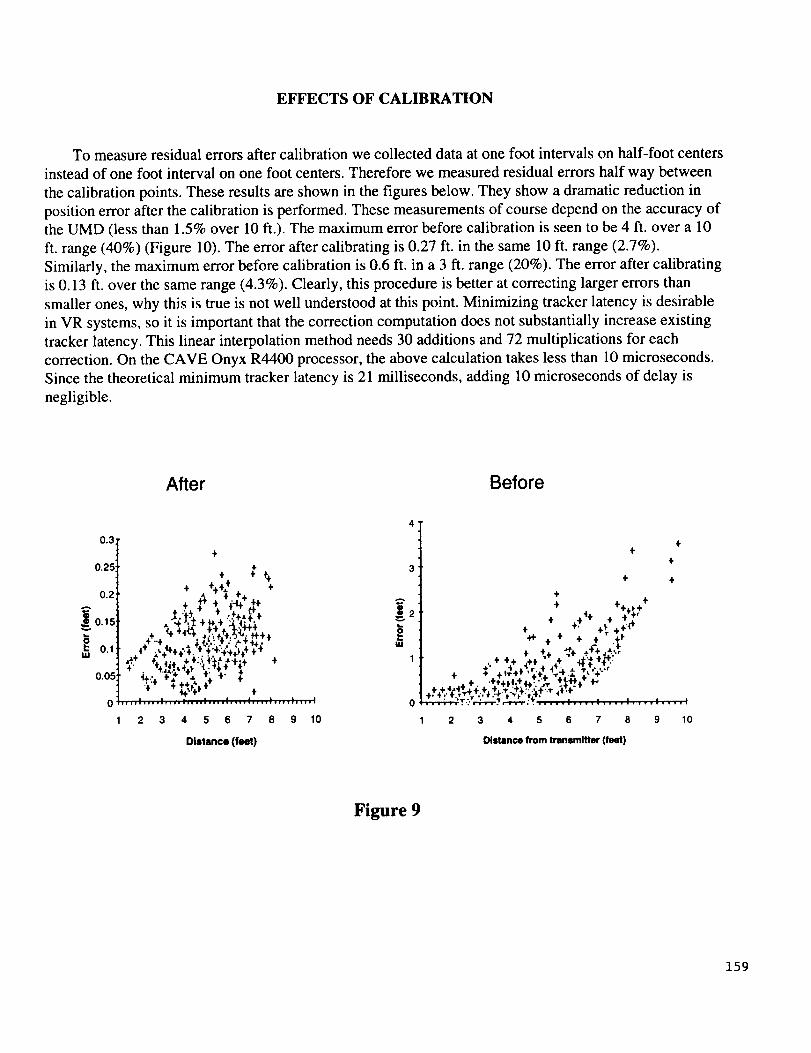
EFFECTS OF CALIBRATION
To measure residual errors after calibration we collected data at one foot intervals on half-foot centers
instead of one foot interval on one foot centers. Therefore we measured residual errors half way between
the calibration points. These results are shown in the figures below. They show a dramatic reduction in
position error after the calibration is performed. These measurements of course depend on the accuracy of
the UMD (less than 1.5% over 10 ft.). The maximum error before calibration is seen to be 4 ft. over a 10
ft. range (40%) (Figure 10). The error after calibrating is 0.27 ft. in the same 10 ft. range (2.7%).
Similarly, the maximum error before calibration is 0.6 ft. in a 3 ft. range (20%). The error after calibrating
is 0.13 ft. over the same range (4.3%). Clearly, this procedure is better at correcting larger errors than
smaller ones, why this is true is not well understood at this point. Minimizing tracker latency is desirable
in VR systems, so it is important that the correction computation does not substantially increase existing
tracker latency. This linear interpolation method needs 30 additions and 72 multiplications for each
correction. On the CAVE Onyx R4400 processor, the above calculation takes less than 10 microseconds.
Since the theoretical minimum tracker latency is 21 milliseconds, adding 10 microseconds of delay is
negligible.
After Before
0.3
0.25
0.2
_0.15
0.1
0.05
0
1
÷
4,
+ : ÷ ÷#_÷÷÷
+ _ ÷4_+ . +,-r,._%.._+÷
4 ..,÷'**¢.÷.' :÷._:,_÷÷÷÷ .,:* +, t;._ 4,÷: t_t*$÷ "*'. 4_,.p÷#
÷tt-¢ ÷.... I .... I .... ; .... ; .... : .... ', .... ; .... ; .... =
2 3 4 5 6 7 8 9 10
Distance (feet)
4'
A
uJ
÷.1-
+
+ +
+
÷ . -' +_ ÷÷_,_+ -F + ÷ ÷ +1-
+_ .,+,..,_÷ .t.._
,..÷v4. + ÷11-÷1"_'.'+_ .,.-I'..,._+"
r-r-v@-_T.: _'_'Tr'rT'r: v. ..... I .... I .... I .... I .... I
2 3 4 5 6 7 8 9 10
Distance from transmitter (feet)
Figure 9
159
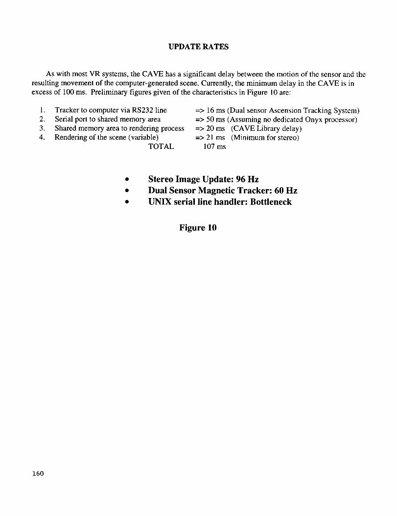
UPDATERATES
As with most VR systems, the CAVE has a significant delay between the motion of the sensor and the
resulting movement of the computer-generated scene. Currently, the minimum delay in the CAVE is in
excess of 100 ms. Preliminary figures given of the characteristics in Figure 10 are:
1. Tracker to computer via RS232 line
2. Serial port to shared memory area
3. Shared memory area to rendering process
4. Rendering of the scene (variable)
TOTAL
=> 16 ms (Dual sensor Ascension Tracking System)
=> 50 ms (Assuming no dedicated Onyx processor)
=> 20 ms (CAVE Library delay)
=> 21 ms (Minimum for stereo)
107 ms
Stereo Image Update: 96 Hz
Dual Sensor Magnetic Tracker: 60 Hz
UNIX serial line handler: Bottleneck
Figure 10
160
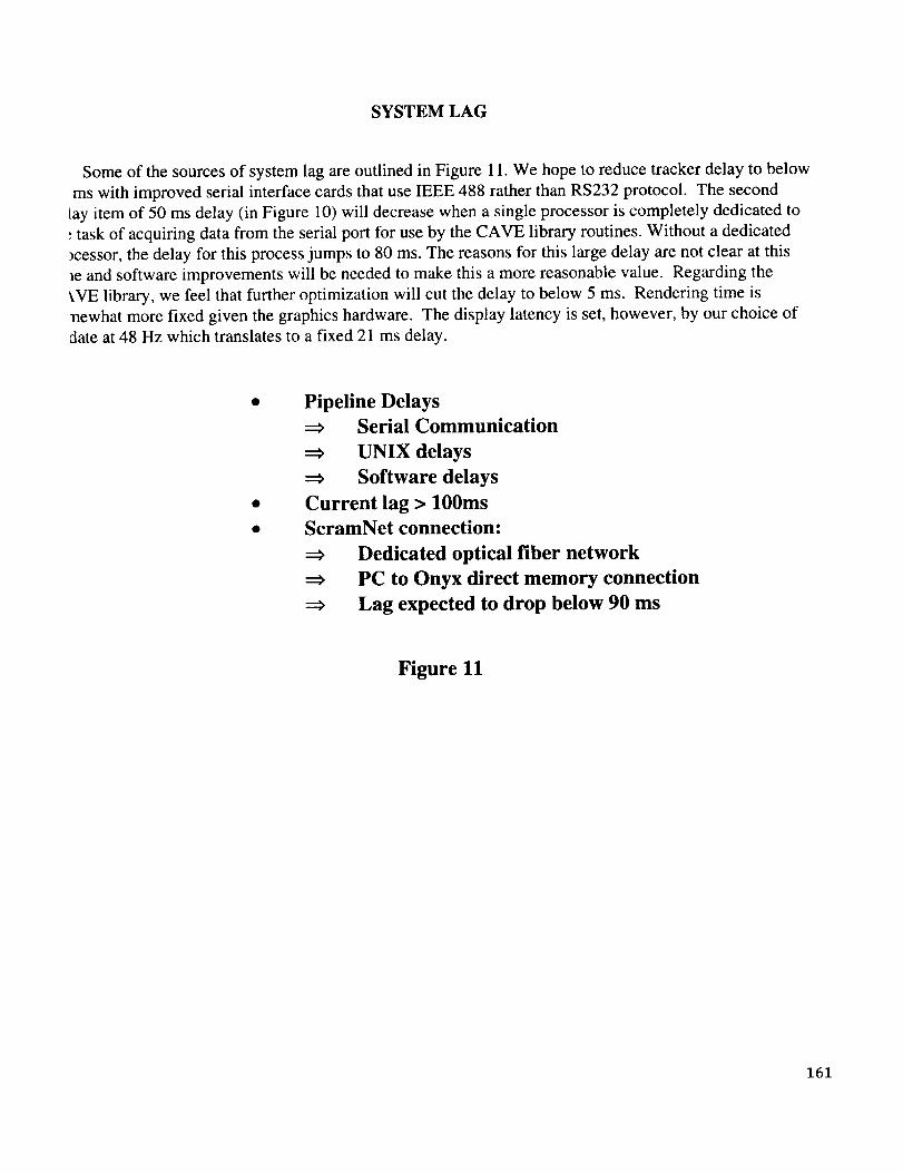
SYSTEM LAG
Some of the sources of system lag are outlined in Figure 11. We hope to reduce tracker delay to below
ms with improved serial interface cards that use IEEE 488 rather than RS232 protocol. The second
ray item of 50 ms delay (in Figure 10) will decrease when a single processor is completely dedicated to
; task of acquiring data from the serial port for use by the CAVE library routines. Without a dedicated
)cessor, the delay for this process jumps to 80 ms. The reasons for this large delay are not clear at this
le and software improvements will be needed to make this a more reasonable value. Regarding the
_,VE library, we feel that further optimization will cut the delay to below 5 ms. Rendering time is
llewhat more fixed given the graphics hardware. The display latency is set, however, by our choice of
date at 48 Hz which translates to a fixed 21 ms delay.
Pipeline Delays
Serial Communication
UNIX delays
Software delays
Current lag > 100ms
ScramNet connection:
Dedicated optical fiber network
PC to Onyx direct memory connection
Lag expected to drop below 90 ms
Figure 11
161
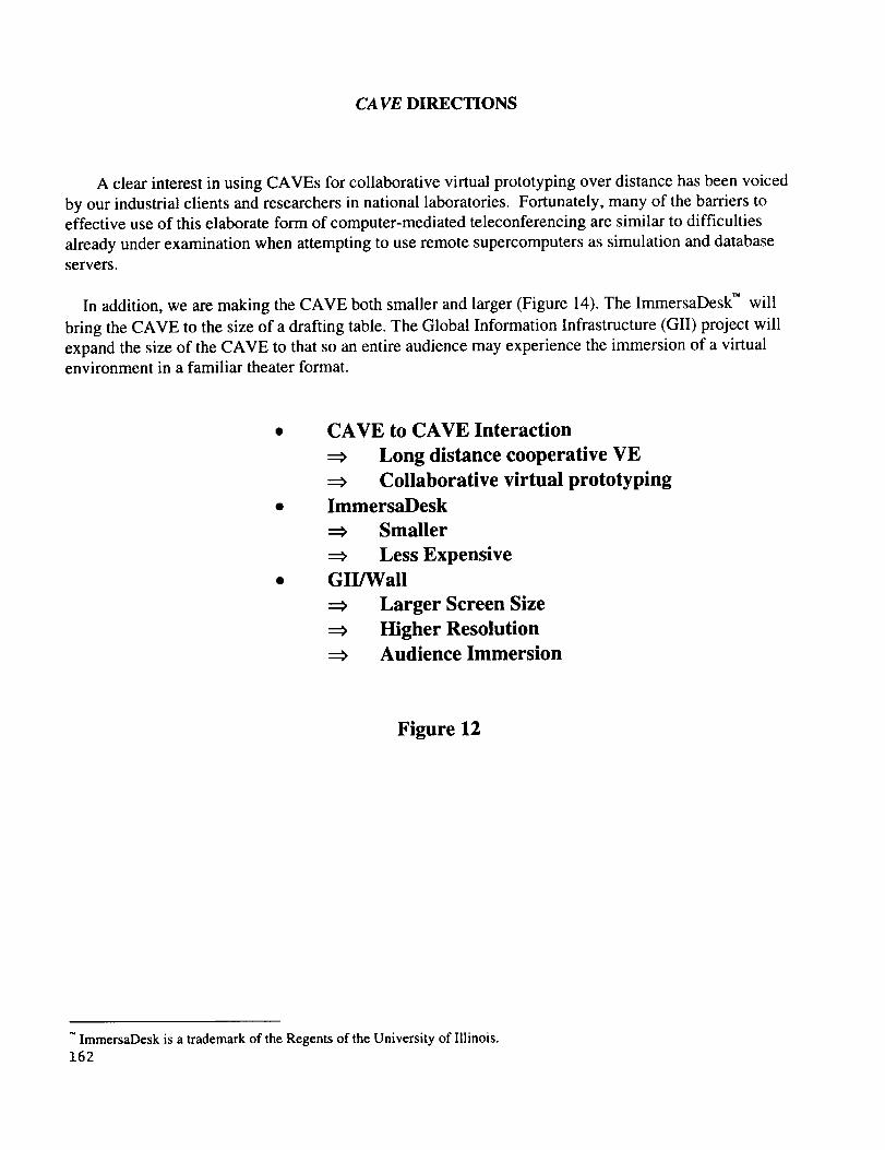
CA VE DIRECTIONS
A clear interest in using CAVEs for collaborative virtual prototyping over distance has been voiced
by our industrial clients and researchers in national laboratories. Fortunately, many of the barriers to
effective use of this elaborate form of computer-mediated teleconferencing are similar to difficulties
already under examination when attempting to use remote supercomputers as simulation and database
servers.
In addition, we are making the CAVE both smaller and larger (Figure 14). The ImmersaDesk TM will
bring the CAVE to the size of a drafting table. The Global Information Infrastructure (GII) project will
expand the size of the CAVE to that so an entire audience may experience the immersion of a virtualenvironment in a familiar theater format.
CAVE to CAVE Interaction
Long distance cooperative VE
Collaborative virtual prototyping
ImmersaDesk
Smaller
Less ExpensiveGII/Wall
Larger Screen Size
Higher ResolutionAudience Immersion
Figure 12
ImmersaDesk is a trademark of the Regents of the University of Illinois.162
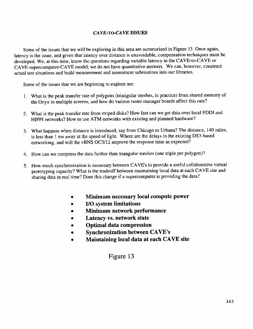
CA VE-To-CA VE ISSUES
Some of the issues that we will be exploring in this area are summarized in Figure 13. Once again,
latency is the issue, and given that latency over distance is unavoidable, compensation techniques must be
developed. We, at this time, know the questions regarding variable latency in the CAVE-to-CAVE or
CAVE-supercomputer-CAVE model; we do not have quantitative answers. We can, however, constructactual test situations and build measurement and assessment subroutines into our libraries.
Some of the issues that we are beginning to explore are:
1. What is the peak transfer rate of polygons (triangular meshes, in practice) from shared memory of
the Onyx to multiple screens, and how do various raster manager boards affect this rate?
2. What is the peak transfer rate from striped disks? How fast can we get data over local FDDI and
HIPPI networks? How to use ATM networks with existing and planned hardware?
. What happens when distance is introduced, say from Chicago to Urbana? The distance, 140 miles,
is less than 1 ms away at the speed of light. Where are the delays in the existing DS3-based
networking, and will the vBNS OC3/12 improve the response time as expected?
4. How can we compress the data further than triangular meshes (one triple per polygon)?
. How much synchronization is necessary between CAVE's to provide a useful collaborative virtual
prototyping capacity? What is the tradeoff between maintaining local data at each CAVE site and
sharing data in real time? Does this change if a supercomputer is providing the data?
Minimum necessary local compute power
I/O system limitations
Minimum network performance
Latency vs. network state
Optimal data compression
Synchronization between CAVE's
Maintaining local data at each CAVE site
Figure 13
163
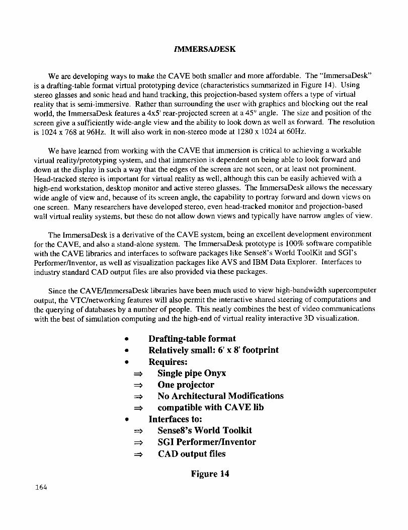
/MMERSADESK
We are developing ways to make the CAVE both smaller and more affordable. The "ImmersaDesk"
is a drafting-table format virtual prototyping device (characteristics summarized in Figure 14). Using
stereo glasses and sonic head and hand tracking, this projection-based system offers a type of virtual
reality that is semi-immersive. Rather than surrounding the user with graphics and blocking out the real
world, the ImmersaDesk features a 4x5' rear-projected screen at a 45 ° angle. The size and position of the
screen give a sufficiently wide-angle view and the ability to look down as well as forward. The resolutionis 1024 x 768 at 96Hz. It will also work in non-stereo mode at 1280 x 1024 at 60Hz.
We have learned from working with the CAVE that immersion is critical to achieving a workable
virtual reality/prototyping system, and that immersion is dependent on being able to look forward and
down at the display in such a way that the edges of the screen are not seen, or at least not prominent.
Head-tracked stereo is important for virtual reality as well, although this can be easily achieved with a
high-end workstation, desktop monitor and active stereo glasses. The ImmersaDesk allows the necessary
wide angle of view and, because of its screen angle, the capability to portray forward and down views on
one screen. Many researchers have developed stereo, even head-tracked monitor and projection-based
wall virtual reality systems, but these do not allow down views and typically have narrow angles of view.
The ImmersaDesk is a derivative of the CAVE system, being an excellent development environment
for the CAVE, and also a stand-alone system. The ImmersaDesk prototype is 100% software compatible
with the CAVE libraries and interfaces to software packages like Sense8's World ToolKit and SGI's
Performer/Inventor, as well as" visualization packages like AVS and IBM Data Explorer. Interfaces to
industry standard CAD output files are also provided via these packages.
Since the CAVE/ImmersaDesk libraries have been much used to view high-bandwidth supercomputer
output, the VTC/networking features will also permit the interactive shared steering of computations and
the querying of databases by a number of people. This neatly combines the best of video communications
with the best of simulation computing and the high-end of virtual reality interactive 3D visualization.
• Drafting-table format
• Relatively small: 6' x 8' footprint
• Requires:
Single pipe Onyx
One projector
No Architectural Modifications
compatible with CAVE lib
• Interfaces to:
Sense8's World Toolkit
SGI Performer/Inventor
CAD output files
Figure 14
164
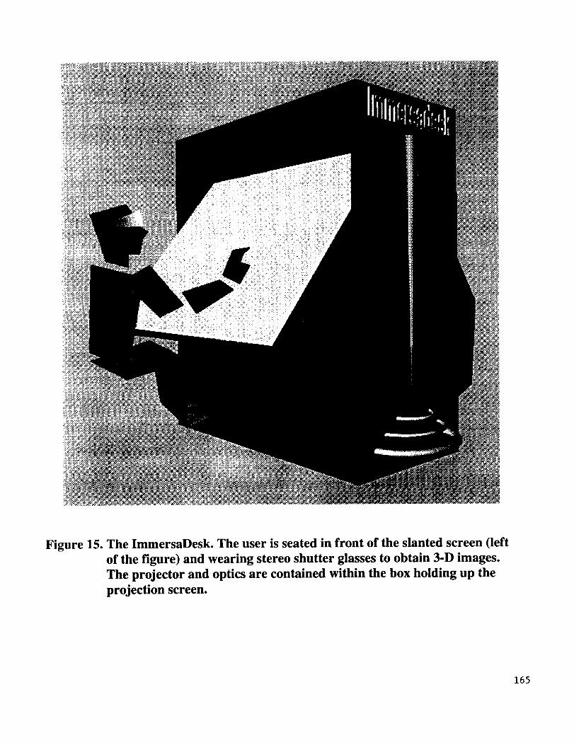
Figure 15. The ImmersaDesk. The user is seated in front of the slanted screen (left
of the figure) and wearing stereo shutter glasses to obtain 3-D images.
The projector and optics are contained within the box holding up the
projection screen.
165
GII/WALL
The Super Computing'95 Global Information Infrastructure (GII) Testbed event provides a venue for
inter-active 2D and 3D demonstrations of National Challenges and Grand Challenges - remotely
computed in a scientist's numerical laboratory and then transmitted over high-speed networks for
presentation in San Diego. The characteristics of this large format CAVE is outlined in Figure 15.
The GII/Wall is a large-screen, high-resolution (1600 x 2048) stereo projection display. A non-stereo
PowerWall was developed by Paul Woodward's group at the Army High Performance Computer Research
Center at University of Minnesota for the Silicon Graphics' booth at SC'94.
The GII/Wall uses four Reality Engines spread across two Power Onyxes to achieve high-resolution,
high-intensity, passive-stereo images. One Onyx controls the top half of the screen and the other controls
the bottom half (each at 1600 x 1024). The top and bottom are each driven by two Reality Engines
displaying polarized projected images for each eye. Throwaway polarized glasses can be used by the
audience instead of the active stereo glasses used in the CAVE and ImmersaDesk systems. The GII/Wall
is much more suited for audiences, and although it uses a lot of computers and projectors, the number of
people it reaches per unit time is far greater than either the CAVE or the ImmersaDesk.
The GIUWall achieves its immersion by wide-screen projection, but does not allow, unfortunately, a
way to look down, a problem with any normal audience seating arrangement. (Note that the angle of
Omnimax/Imax theater seating addresses this problem by steeply pitched seating). The developers are
currently experimenting with large-area types of tracking, mindful of the fact that it is only possible to
track one person at a time, not an audience. The GII/Wall is appropriate for applications in which high-
resolution telepresence is the goal rather than audience participation.
Goal:
High resolution telepresence for large audiences
Not for audience participation
Large Screen/Wall Viewing
High Resolution (1600 x 2048)
High Intensity (lightvalves)Passive Stereo
2 Power Onyxes:
Each with 2 SGI Reality Engines
---> One Onyx Each for top and bottom image
Networked scaleable computing
Figure 16
166
SUMMARY
In summary, an alternate form of a Virtual Environment presentation system has been described. The
general characteristics of its visual, auditory, tracking, and image generation systems have been detailed.
Specific problems associated with this system have been addressed and effective solutions have been
shown.
In addition, two derivatives of this system have been presented: The ImmersaDesk(TM) and the Global
Information Infrastructure Wall. The first represents a smaller, less expensive, multi-person immersive
system. The second, a larger, audience style, presentation format of an immersive environment.
Finally, interconnection of all these VE systems was discussed with the goal of collaborative virtual
prototyping for science and industry.
167