- Radio Corporation of America - - Radiolaville.com grand.pdf · 2010-02-25 · - Radio Corporation...
27
Radiola Grand Loud Speaking Radio Receiver MANUFACTURED BY Westinghouse Electric & Manufacturing Company for - Radio Corporation of America - TYPE RG STYLE 365102
Transcript of - Radio Corporation of America - - Radiolaville.com grand.pdf · 2010-02-25 · - Radio Corporation...

Radiola Grand Loud Speaking Radio Receiver
MANUFACTURED BY
Westinghouse Electric & Manufacturing Company for
- Radio Corporation of America -
TYPE RG
STYLE 365102

Fig. 1 — Radiola Grand With Cabinet

Radiola Grand Loud 5peaking Radio Receiver
TYPE RG STYLE 365102
Receivers INTRODUCTION:
A radio receiver is an instrument which, in connection with an antenna, in the form of an elevated wire, or suitable loop, is used to convert the high frequency ether or wireless waves into sound waves in air and enable the reception of speech, broadcast programs or telegraphy.
The radio or wireless waves are transmitted from the sending station in all directions and travel at the speed of light or 186,000 miles per second. Such waves can not be heard because they have no mechanical effect on the ear drum and because they have a frequency of vibration far too high to be audible. Sound waves in air travel only 1100 feet per second and have a frequency or vibration of from 16 cycles per second, the note of the largest organ pipe, to about 15,000 cycles per second, the overtones or harmonics of the human voice and musical instruments. The wireless waves are very much longer than sound waves but their velocity of propagation is so high that their passage at a given point causes an ether vibration of from 20,000 to 3,000,000 cycles per second. Thus 300 meter (980 foot) waves passing at the rate of 186,-000 miles per second cause a frequency of vibration of 1,000,000 cycles.
Many people confuse the wave length with the distance from which signals can be heard, while as a matter of fact, when we say that 360 meters is the wave length of a broadcasting station/we mean that the continuously radiated waves from the transmitter are 360 meters (1180 feet) long from the crest of one wave to the crest of the next.
The radio waves are not transmitted at a variable frequency corresponding to the sound wave, but are transmitted at a substantially constant high frequency and the sound is represented by the variation of intensity or the modulation of the high frequency carrier wave.
The ordinary wire line telephone receives electric currents of the same frequency as the sound waves, which it gives out by the vibration of the receiver diaphragm. The radio
receiver must do more than transform the voice frequency current into sound waves. Briefly the operation is as follows: The ether waves traveling in space at constant velocity, constant frequency and variable intensity (amplitude), induce corresponding electric currents in the antenna circuit by sympathetic vibration, when the antenna circuit is in tune with the transmitted wave. These electric currents in the antenna circuit are changed to voice frequency currents in the detector circuit of the instrument. The latter currents cause the vibration of the diaphragm of the headset or loudspeaker just as in the ordinary telephone.
CLASSES OF RADIO RECEIVERS:
There are several types or classes of radio receivers, varying in sensitivity, price and ease of operation.
1. The Crystal Receiver is the simplest and most inexpensive receiver. It detects the voice variations of the radio frequency antenna current by the rectifying effect of certain sensitive crystals. Such a receiver is capable of receiving signals within 25 miles or so from present broadcasting stations, depending, of course, on the power of the station. It must be used. with a headset as all the energy available to produce the sound waves is ob-tained from the intercepted radio waves.
2. The Vacuum Tube Receiver may take the form of an electric circuit with a vacuum tube used in place of a crystal detector. This receiver is more sensitive than the crystal receiver since it uses the energy in the antenna to control a larger amount furnished by a battery, but the sensitivity is still limited and head telephones must be used.
3. The Detector Amplifier Receiver is an instrument in which the signal is detected by crystal or vacuum tube and amplified by one or more stages of vacuum tube amplification. Such a combination is capable of receiving more distant signals and working a loud speaker.
4. The Regenerative Receiver. By means of the regenerative circuit, amplifica-

Radiola Grand Loud Speaking Radio Receiver
tion and detection with a single tube may be obtained in a receiver which will give great sensitivity for distant signals.
5. The Regenerative Loud Speaking Receiver combines the good features of. 3 and 4 giving an instrument which is sensitive for distant reception and has regeneration and audio amplification to build up the signal for a loud speaking device.
THE RADIOLA GRAND:
The RADIOLA GRAND is a receiver of the fifth class. It is equipped with a regenerative circuit, 4 dry cell vacuum tubes and a self contained loud speaker. The instrument has been designed by the makers to give a strong signal without distortion and to be sensitive, compact, efficient, free from disagreeable tube noises and simple to operate. It will respond to wave lengths from approximately 180 to 530 meters, and is very selective.
It is impossible to rate a radio receiver in miles from which signals can be received, as the strength of signal depends upon atmospheric disturbances and conditions which are very irregular.
The RADIOLA GRAND is unique, in that it is a complete radio receiving set including a self contained loud speaking receiver. It combines maximum sensitivity with sufficient amplification to give good volume to the loudspeaker output. This instrument has quite regularly reproduced in good volume broadcast programs from stations 1000 miles distant. This set on an efficient antenna can be depended upon to receive any signal that is of sufficient strength to be received satisfactorily by any radio receiver.
One of the principle features of this instrument is the use of the low current vacuum
tubes which can be operated with ordinary
dry batteries thus eliminating the storage battery.
Several other distinct features such as a powerful
amplifier, a high grade loud speaker and mechanical
features to eliminate vibration, make this instrument
the ideal radio receiver for the reception of
broadcast programs.
Fig. 2—Radiola Grand
Equipment STANDARD EQUIPMENT:
The standard equipment or RADIOLA
GRAND Style 365102 is shown in Figure 3.
It consists of: 1 Cabinet type Receiver with "B" and "C"
batteries enclosed.
4 Radiotron 1 1/2 volt Dry Cell Vacuum Tubes, Type WD-11, Style 319533.
2 Antenna Terminal Connectors. 1 Set Battery connecting Wires. 1 Special Connector for Battery Posts.
ADDITIONAL EQUIPMENT NECESSARY:
It is necessary to have on hand the following additional equipment for the installation of the RADIOLA GRAND:
4 No. 6 Dry Cells (ordinary door bell or ignition cells.)
1 Complete set of Antenna Material Type AD Style 319486.
For the convenience and to meet the re-quirements of the Fire Underwriters, it is

Radiola Grand Loud Speaking Radio Rec
Fig. 3—Radiola Grand—Standard Equipment
recommended that the Radio Corporation antenna package as specified on page 4 should be obtained, as it contains approved equipment and gives directions for the installation of a proper out-door antenna.
ALTERNATE AND EXTRA EQUIPMENT:
1 Mahogany Stand Style 325980. 3 Edison primary cells (200 ampere hour) or 1 2-Volt lead storage battery cell. 1 Telephone headset Type FC, Style 358078. 1 Telephone plug Model UD 824.
Figure 1 shows the RADIOLA GRAND mounted on the special stand listed above. This stand provides a place for the batteries as well as a convenient support for the instrument.
The Edison primary Batteries or 2-volt storage cell may be used in lieu of the dry batteries when desirable.
CABINET RECEIVER: The Cabinet Receiver consists of a well-finished
mahogany cabinet containing all the necessary radio apparatus, plate batteries, loud speaker and horn. This piece of equipment, with tubes installed, makes a complete
installation except for the antenna and .the batteries to heat the filaments of the tubes.
The control board of the receiver is in the upper part of the cabinet and exposed when the lid is opened. This control board has four openings for the insertion of the vacuum tubes, four control knobs and a tuning lever.
The control board is hinged at the back edge and held by two screws in the front corners. On the under side of the control board are mounted the regenerative circuit apparatus consisting of transformers, tuning coils, rheostats, bias battery, condensers, tube sockets, etc. Securely mounted on the walls and bottom of the cabinet are the antenna condensers, plate or "B" batteries and loud-speaking horn. Figure 9 shows an inside view of the lower compartment of the cabinet but it should be noted that with proper care there will be no occasion to open the compartment except to renew batteries as explained under "MAINTENANCE." If any parts should be injured or thrown out of adjustment, a radio service man or an electrician can trace and correct the trouble by referring to the diagram of circuits and the instructions which follow.
Before shipment this receiver was thor-

Radiola Grand Loud Speaking Radio Receiver
oughly tested and found to be in good operating condition. After installing the antenna, connecting the antenna wire, ground wire and dry battery to the terminals at the back of
the cabinet and inserting the four vacuum tubes as explained under "INSTALLATION", the RADIOLA GRAND will be ready for operation.
Installation LOCATION:
The RADIOLA GRAND should be located as near as practicable to the incoming wire from the antenna. Certain limitations in the room and certain limitations in the location of an antenna often make it difficult to locate the instrument directly under the near end of the antenna. However, in all cases, arrangements should be made to meet this requirement as closely as possible.
ANTENNA:
General: Most of the operating troubles in radio broadcasting receivers are traced to poor installation of the antenna. There are several things which govern the size, location and type of antenna installation. If the antenna is not properly insulated the signals will be weakened by leakage. If the antenna runs parallel to electric light wires or grounded metal parts its efficiency will be much reduced. If all joints in the working part of the antenna circuit are not soldered or provided with approved splicing devices, they will corrode and reduce the signal because of the introduction of high resistance. If the antenna is too low, or short, the strength of signal will be reduced. If the antenna is too high and long the receiver will not give good selectivity, i.e., it will be impossible to tune out nearby strong signals and select a distant or weaker signal.
Size: The best antenna for all around receiving consists of a single wire, size 14, B & S gauge, installed 15 to 30 feet from the ground and extending horizontally 100 to 130 feet from the receiver. This antenna should
be equipped with approved protective device and installed in strict accordance with the rules of the National Fire Protection Association.
When the above rules are followed and the technical points mentioned above are properly considered, the antenna will give good signals and will be no fire or lightning hazard.
For stations located in cities in which there are high power broadcasting stations it is advisable to install a small indoor antenna which can be used for receiving the strong signals from nearby stations as will be explained under "OPERATION". Such an antenna, if installed entirely within the house, needs no protective device and is not subject to the rulings of the National Fire Protect! on Association.
The indoor antenna should consist of a copper wire about No. 20 B & S gauge double silk covered starting above the RADIOLA GRAND and extending 10 to 25 feet along a picture moulding or suspended in any other available space. It is preferable to use an outside wall as it is usually free from embedded electric light wires, gas pipes, etc. The height of this small antenna will depend upon the strength and proximity of the neighboring stations. For very strong signals it is sufficient to have it along the upper part of the same room. In other cases the horizontal part of the antenna can be strung one floor above. The inside antenna will not be satisfactory in modern houses with metal lathing, and in large buildings with steel frame-work the signals may be considerably reduced. It will, however, under satisfactory conditions, perform practically as well as an outdoor antenna of the same dimensions.
•Ground
Fig. 4—Diagrammatic Antenna
6
To Support To Support
To Antenna Post of_
Radio Receiver.
-——Down Lead
^Protective Device

Radiola Grand Loud Speaking Radio Receiver
Fig. 5—Antenna Package
ANTENNA PACKAGE: Figure 5 shows the complete antenna package
equipment, type AD and Figure 4 shows diagrammatically how an antenna should be installed. The center span of wire between insulators is the working span and is connected to the instrument by the "down-lead" or lead-in wire, the end of which is to be equipped with special terminal provided with the RADIOLA GRAND. The protective device provides a discharge path from antenna to ground, and thus protects the antenna and receiving set during electrical storms.
UNDERWRITERS RULES: The following quotations from the Underwriter's
rules will be of value. "The outside antenna must not be placed over or
under power or electric light wires of any circuit of more than 600 volts, or railway trolley or feeder wires, nor shall it be so located that a failure of either the antenna or the above mentioned electric light or power wires can result in contact between the antenna and power wires. Antennae shall be constructed and installed in a strong and durable manner."
"Each lead-in wire shall be provided with an approved protective device properly connected and located (inside or outside the build
ing) as near as practicable to the point where the wire enters building." "The protector shall not be placed in the immediate vicinity of easily ignitable stuff or where exposed to inflammable gases or dust, or flying combustible material."
"The protective ground wire may be bare or insulated and shall be of copper or approved copper-clad steel. If of copper, the ground wire shall not be smaller than No. 14 and if of copper clad steel it shall not be smaller than No. 17." "The ground wire shall be run in as straight a line as possible to a good permanent ground. Preference shall be given to water piping. Gas piping shall not be used for grounding protective devices. Other permissable grounds are grounded steel frames of buildings or other grounded metallic work in the building and artificial grounds such as driven pipes, plates, cones, etc.". "The ground wire shall be protected against me-chanical injury. An approved ground clamp shall be used wherever the ground wire is connected to pipes or piping."
"The receiving equipment ground wire may be bare or insulated and shall be of copper or copper .clad steel as in the case of the protective ground wire." "The receiving

Radiolo Grand Loud Speaking Radio Receiver
equipment ground wire may be run inside or outside the building. V/hen receiving equipment ground wire is run in full compliance with the rules for protective ground wire it may be used as the ground conductor for the protective device."
ANTENNA CONNECTION: With the RADIOLA GRAND two special
terminals are provided for attachment to the end of the antenna lead-in, for convenient switching between antenna posts. If two antennae are used, one of the special terminals should be connected to each connecting wire as follows: Unscrew the hard rubber part from the knurled brass edge. Now insert wire from small end of hard rubber piece, bending end over slightly to a distance of about ^Q inch. Screw the two parts together again and it will be found that the wire or stranded conductor will be tightly clamped in the terminal device. This terminal will fit the upper two antenna posts on the back of the cabinet and will allow ready connection of either antenna to either the long or short wave post.
GROUND CONNECTION: The ground wire shall be connected from the left
hand binding post on the back of the instrument marked "+AI and ground." This ground wire should run as directly as possible to a permanent ground, as indicated in the rules quoted above.
CONNECTION OF FILAMENT OR "A" BATTERIES:
Dry Batteries: The vacuum tubes used in the RADIOLA GRAND require a filament voltage slightly over 1 volt so that an ordinary dry cell can be used to heat the filament. Four dry cells are used in parallel, or separately to heat the filament of each tube. In order to prevent the circulating currents due to slight difference in the connection of the various cells and also to show when and which cell has been exhausted, the four "A" bat-teries should be connected up each to feed a separate tube. Figure 6 shows a diagrammatic connection for the 4 dry cells. The negative terminal of each cell is connected by a common wire to the right hand binding post marked "common A negative." The Positive terminal of each of the four cells is separately connected by a wire to the corresponding post marked "+A1, +A2, +A3 and +A4”
1
Fig. 6—Diagrammatic Connection of Dry Cells
Edison Primary Cells: Edison primary cells are sometimes more desirable for "A" batteries as their life is long and they have no self discharge. Three cells must be used, connected in series, and the positive terminal of the battery should be connected to all of the four posts of the RADIOLA GRAND marked +A. For convenience a special connector is provided to connect these four posts together and only 2 wires will be needed connecting the battery to the cabinet.
Two-Volt Storage Cell: If desirable, a single 2-volt storage cell may be used, connected as in the case of the Edison primary batteries. Use but one 2-volt storage cell as a higher voltage will burn out the tube filament. If a storage cell is used it may be placed in a special mahogany stand or it may be placed in the basement out of the way and where the battery may conveniently be charged and kept in order. When the storage cell is placed in the basement it may be convenient to connect the ground wire to the positive (+) post of the cell to avoid running an extra wire up to the terminal on the cabinet.
Caution: When a storage cell is used care must be exercised in adjusting the filament rheostat. Never turn the filaments up too high as they will be injured and may be burned out, if the rheostat is turned too far to the right.

Radiold Grand Loud Speaking Radio Receiver
INSERTION OF TUBES: Before inserting the four vacuum tubes, turn
filament rheostat knob on control board to the "off position, i.e., as far to the left as possible. Each vacuum tube has one large and three small pins in the base and it will be found that the spacing and size of these pins is such that the tube can be inserted in the tube socket of control board in only one position. For convenience the gold headed tack in front of the tube opening is used to indicate the position of the large pin of the tube. Always insert tube with large pin in line with the gold headed tack. CLEANING THE CABINET:
The paraffined corks in the shipping box will leave a greasy and mottled surface on the cabinet. After installation the cabinet should be cleaned by wiping with a solution of alcohol and water on a piece of cheese cloth.
Use a tablespoonful of alcohol in a quart of
water. Care should be used not to get the cabinet too
wet in cleaning, especially around the terminals on the back of the instrument. Wring out the cloth so that it will not drip or allow the solution to run into the cracks. Dry the instrument immediately after cleaning, with a soft dry cloth, and use only the dry cloth near the terminals if a satisfactory cleaning can be obtained. The water solution, specified above, is conducting and may cause leakage and affect the signals for several hours if the surface of the wood near the terminals is wetted with it.
After the first cleaning, specified above, to remove the wax and oil on the mahogany cabinet, the surface may be kept clean with any good furniture polish or dry cleaning method.
Operation
GENERAL:
The RADIOLA GRAND is made as simple in operation as is consistent with good quality, selectivity and strength of signal. It will be found very easy to pick up signals from the different broadcasting stations and with a little practice it will be possible to receive distant and weak signals so that with careful tuning and regeneration they may be magnified sufficiently to work the loud speaker. Many things affect the reception of radio signals such as atmospheric conditions, interference of nearby stations and the proximity of wave lengths of the station desired and that of other stations. A little practice will make the operator proficient in the operation of the instrument.
CONTROLS AND TUNING: Figure 7 shows a close-up of the control board which is used to tune-in and amplify signals and make all adjustments during operation. The purpose and effect of each control knob is as follows:
Filament Rheostat: The filament
rheostat is used to turn on and control the current through the filaments of the four vacuum tubes. When this is turned all the way to the left, and to the point marked "off" the circuit is open and no current flows from the "A" batteries. The control dial is divided into four parts. If dry cells are used for
Fig. 7—Close-Up View of Control Board
AA—Filament Rheostat
AB—Volume. AC—2nd Stage Amplification.
AD—1st Stage Amplification. AE—Detector.
AF—Tickler. AG—Tuner. AH—Vernier
"A" batteries it will be necessary to place the rheostat pointer somewhere between 2 and 4 on the dial, depending upon the

Radiola Grand Loud Speaking Radio Receiver
condition of the batteries. If Edison primary cells are used, the correct operating position for the pointer will be between 2 and 4, while if a storage cell is used the pointer should be set somewhere between 1 and 2.
(CAUTION) Always turn this control off when not in use to save batteries and lengthen life of vacuum tubes.
Volume Control: The knob for con-trolling the volume of loud speaker signal is located on the right hand side near the back of the panel. By means of this knob, resistance is thrown in shunt to the amplifier giving 6 different strengths of Signal from "soft" to "loud". Where great signal strength is undo sired marked increase in tone quality will be obtained by turning the control toward "soft."
Tuning Lever: The tuning of the instrument is done by means of the lever co-operating with the large dial and located near the center of the panel. When the index points to zero it is set for the shortest wave length and when it points to ten it is set for the longest wave length (The range depending upon antenna post used.)
Vernier Control: It is sometimes very difficult to tune in a distant signal with the tuning lever as the tuning point is very sharp, and if the lever is turned but a fraction of a division from the proper setting, the signal will be entirely lost. In order to facilitate accurate tuning the "Vernier" knob is used. The complete scale on this dial corresponds to only 1 or 2 sub-divisions on the tuning dial and makes it very easy to get accurate tuning. This control should normally be set at "5" which will allow variation either way.
Tickler Knob: The "Tickler" knob is used to adjust the regenerative amplification of the signals. This tickler method of regeneration has the advantage of being very simple to control and so designed that approximately the same setting can be used for any position of the tuning lever. Care should be exercised not to turn tickler knob too far as this tends toward increase of distortion, noises and static. If the tickler adjustment has little effect on nearby stations, it indicates that the antenna is too long.
The efficient and proper use of the tickler knob will come with practice.
HUNTING SIGNALS:
Start with the volume control turned to "loud," the vernier at "5", all other knobs turned as far as possible in the counter-clockwise direction and the antenna connected to the "Shortwave" binding post. Now turn the filament rheostat knob slowly to the right until the filaments in the tubes appear cherry red when viewed through the top of the metal structure in the tube. Be sure that all tubes heat up when the rheostat is turned on.
Turn tuning lever slowly back and forth over the scale, at the same time listening for signal from the horn. If no signal or music is found, increase the amplification by turning the tickler knob clockwise by successive steps with the left hand while the right hand continues to search with the tuning lever by turning same back and. forth slowly over the scale. If by this time no signals have been found it is an indication that no station within range is transmitting within the wave length range for the antenna post used, or something is wrong with the installation. Try again by connecting the antenna lead to the "Longwave" antenna post and hunting signals as before.
When the antenna is connected to the short wave antenna post the RADIOLA GRAND will respond to wave lengths from. approximately 180 to 350 meters. When connected to the long wave post it will respond to wave lengths from approximately 320 to 530 meters.
In the neighborhood of large cities and at the popular broadcasting hours, several signals of various strength can usually be found on each range of wave length.
If a weak or distant signal is to be received it is sometimes desirable to use a telephone headset plugged into the jack on the lefthand side of the cabinet. When the "Plug" is inserted the "Loudspeaker" in the instrument is automatically cut out and the "Headset"" thrown into circuit.
FINAL ADJUSTMENT OF FILAMENT
RHEOSTAT:
In order to increase the life of the vacuum tubes the filament rheostat should be adjusted for as low a filament current and tempera-
10

Radiola Grand Loud Speaking Radio Receiver
ture as is possible without affecting quality or strength of signal. While the instrument is working, on a relatively strong signal or music, adjust the rheostat to the point where the strength of signal starts to fall off if the current is further lowered.
REGENERATION:
The tickler is a device which is used to amplify the signal by regeneration, and it will be noted that the strength of signal (except very strong nearby signals) increases as the knob is turned to the right. At a certain point the receiving circuit starts to oscillate, above which any increase in tickler adjustment will not increase the strength of signal.
The proper adjustment depends upon the strength of signal. With very strong signals the tickler will be of little or no value. When amplification for weak or distant signals is desired, turn the tickler knob to the right slowly until the desired strength of signal is obtained. If the knob is turned too far to the right, the set will start to oscillate and the music or speech will become distorted, noisy or mushy. When this occurs, the tickler knob should be immediately turned to the left until the signals again become clear. Any further amplification if possible should be obtained by accurate adjustment of tuning with the "Vernier" knob.
The oscillating point on the tickler dial will depend upon the antenna efficiency and the current in the detector tube filament. With an average antenna the oscillating point should be about midscale with a normal filament current. As the temperature of filament is increased the point of oscillation will occur at a lower tickler setting and vice cersa.
The instrument is so designed that under average conditions about the same tickler adjustment is suitable for all wave lengths, so that signals of reasonable strength can readily be found by adjusting "Tickler" just below the oscillating point and turning the tuning lever over the scale. For very weak signals careful adjustment of the tickler must be made to keep the set just under oscillation as the tuning lever is used to search at different wave lengths.
The tickler setting for oscillation can easily be
told after some experience. When the
tube begins to oscillate there is a characteristic
change in the sound of signals and static noises, or
there is a breathing or whistling sound. In case the
ether is very quiet it may be impossible to
distinguish oscillation bv the above characteristic
sounds, in which case a test may be made by
touching the metal of the antenna post with a
moistened finger. If there is a sharp click in the
receiver or horn, both when the finger is brought in
contact and removed, then the tube is oscillating.
When not oscillating there will be only a single
click or none at all.
When the receiver is oscillating it is transmitting
continuous waves of a wave length corresponding
to the wave length setting of the tuning lever. If
now the lever is turned slowly over the scale there
will be a whistling sound produced when the
tuning passes through the setting for some
incoming signal. This is an interference or beat
between the waves from the receiver and those
from a distant station, and the pitch is determined
by the difference in frequency of the two waves.
Any other receiving set which may be tuned to the
same wavelength and is not too far away will also
hear the same beat note. When several oscillating
receivers in the same neighborhood all produce
beat notes of different pitches the effect is very
annoying. There-fore care should be taken never
to let a receiving set oscillate when hunting for
or listening to signals.
SOUND VOLUME CONTROL:
When the signal is too loud it may be decreased in volume by several methods. The "Volume" control knob can conveniently be used in most cases when the reduction of tickler to zero is not sufficient. With very strong signals, there may still be too much volume and some distortion when the volume control is at "soft." To correct this, use the smaller antenna if available.
Lowering volume of sound by turning down the tube filaments results in distortion.
Detuning the receiver is often desirable and effective to lower the sound volume but in many cases will increase the strength of an interfering signal on a nearby wave length.
11

Radiola Grand Loud Speaking Radio Receiver
Maintenance GENERAL:
With care in handling during shipment, installation and operation nothing in the RADIOLA GRAND should wear out or require replacement beyond the renewal of vacuum tubes and batteries. In rare occasions it may be necessary to replace a grid leak condenser in case moisture has entered the structure. The following detailed instructions cover the renewal of tubes and batteries.
RENEWAL OF VACUUM TUBES: The RADIOLA GRAND normally uses 4 WD-
11 Style No. 319533 Radiotron dry cell vacuum tubes. These tubes have an unusually long life if they are not abused by rough handling or over-heating of the filament. The instrument will work with three tubes only so that in case of a burn-out or injury to one tube, operation may be continued until a renewal is obtained.
The first tube on the right is the detector tube, the second tube from the right is the first amplifier and the third and fourth tubes •together form the second stage of amplification in the form of a "push-pull" amplifier. The detector and first amplifier are essential in the operation of the instrument. However, only one tube in the second stage is necessary to operate the instrument. If any tube should burn out, rearrange the tubes so that the empty socket will be the third or fourth from the right. With three tubes operating the instrument will not handle very loud signals without distortion but will give satisfactory music of low intensity.
RENEWAL OF “A” BATTERIES:
Dry Batteries: The filament current batteries or
"A" batteries will become exhausted from time to time and require renewal. The life of such batteries will depend upon the type, size and freshness at the time of installation.
If dry batteries are used, a separate cell is used to feed each tube. This enables the operator to tell when and what dry cell is exhausted as the filament connected to a weak dry cell will not heat up as much as the other filaments. Dry batteries deteriorate even when not in use and it often happens that cells are purchased which have been in stock so long that only a fraction of their useful charge is available. The operator should therefor
purchase new dry cells from a reliable firm that has its stock continuously moving.
Four fresh dry cells of the ordinary size (No. 6) used for ignition and other closed circuit uses should last for about 50 days when used 2 hours per day. When they are discharged they are worthless and should be replaced by similar cells.
Edison Prinary Cells: These cells can be furnished in different types and sizes, the most convenient sizes being 200 or 300 ampere'hours. These cells have the advantage of being practically free from self discharge and can be left standing out of use for long periods without deterioration. This type of cell should not be installed without first reading the instructions which are furnished by the makers.
Three Edison primary cells should be used in series. When they have become exhausted new cells need not be purchased but new chemicals, covering oil and electrodes can be purchased for installation in the old cell.
Two-Volt Storage Cell: If a single lead storage cell is used there is sufficient excess voltage to allow installing the battery in the basement or at some distance from the RADIOLA GRAND where charging and general inspection can conveniently be carried out.
Storage cells of various capacities from 10 to 160 ampere hours can be purchased. A suitable radio battery differs somewhat from the usual automobile battery in that it is designed to hold its charge for a longer time when not in use and it is not called upon for heavy current service. Radio batteries should therefore be used as they will not require as constant attention as the other type.
Some operators prefer to use a battery of small capacity sufficient to operate the RADIOLA GRAND for a period of a few hours. In this case frequent charging of the storage cell is required, and a convenient method is to keep the cell on continuous trickle charge whenever it is not in use for receiving radio signals.
The large capacity batteries are convenient for those who have no charging facilities and wish to operate for periods of several weeks on a single charge of the battery.
RENEWAL OF “B" BATTERIES:
The "B" batteries to feed the plate circuits of the tubes are mounted in the lower com-
12

Radiola Grand Loud Speaking Radio Receiver
partment of the RADIOLA GRAND. In order for the 4 blocks of "B" batteries to fit the special holder for "B" batteries it is recommended that batteries Style 319548 be used.
In making replacements of "B" batteries, be sure to install and connect the batteries exactly as shown in the figure and as they were connected when the instrument was received. Connections in the leads between "B" batteries should be soldered and taped unless the special battery specified above, and having terminals and binding posts, is used.
Each block of "B" battery has a nominal voltage of 22^ volts. All four are to be connected in series with the positive end near the front and connected to the binding post on the right hand side of the box near the end of the wooden clamp held by a wing nut. The negative end of the series connected batteries is connected on the inside of the box to the "+AI and ground" post. The plate circuit of the detector tube is connected for 22
1^ volts and the
wire extending from the cable in the back of the box is to be connected to the junction between the first and second blocks of battery.
When the connections have been completed they should be carefully checked as failure to make the proper installation of batteries will make the instrument inoperative and may discharge one or more of the batteries.
Fresh batteries of the size specified above should last from 6 to 10 months with a normal use of the instrument for one to two hours per day.
RENEWAL OF "C" BATTERIES:
The "C" battery consists of a 3-volt, 2-cell pocket flash light battery mounted in a special clip on the under side of the control panel. The old "C" battery should be removed by lifting the spring member extending to the base of the battery and pulling the unit away from the small terminal block and holding clip. It should be noted that the metal strip terminals of the battery make contact only when inserted in the proper way. If the battery is turned over there will be no circuit and the instrument will not operate without howling or making disagreeable distorted signals.
Several makes of flashlight battery are suitable for the "C" battery of the RADIOLA GRAND. The Eveready Tungsten Battery No. 750 can be recommended for this unit. This battery is only required to maintain the potential of the grid circuit of the instrument, and therefore does no work and will last for several months and until it becomes exhausted by internal action. The first symptom of a discharged "C" battery is usually distortion of signals followed later by howling.
REPLACING GRID LEAK CONDENSER: The combined grid leak and condenser mounted
in fuse clips under the vacuum tube board should not require replacement. However, if moisture enters this unit it may change and affect the operation of the instrument. In this case, it is advisable to replace it with. a new grid leak and condenser Style 319562 or at least try a new one in the fuse clips to see if faulty operation is due to a defective unit.
RENEWAL OF RUBBER MOUNTINGS: After several years of operation the rubber
mounting strips supporting the sub panel and the detector tube socket may deteriorate by hardening or sagging. If these strips should sag so that the sub panel or detector tube is . not freely supported the rubber should be removed and replaced with new rubber strip.
OPERATING TROUBLES: It is impossible to give in detail complete
instructions to cover all the possible variations in operation which may come up. The above instructions on "Maintenance" cover only the usual renewal which can be made by the non-technical operator. Troubles such as broken wires, damage by lightning, burn out by misconnection of batteries, etc., are difficult to locate except by a radio service man and if tlie usual renewal of batteries and tubes does not bring the instrument into good operating condition, a good Radio Electrician should be called in to locate and eliminate the trouble.
In order to help a repair man or operator who understands radio circuits and apparatus to correct any operating fault the following description of the electric circuit is included with diagram of connections.
13

Radiola Grand Loud Speaking Radio Receiver
Fig. 8—Diagram of Connections
14

Radiola Grand Loud Speaking Radio Receiver
The Electric Circuit The schematic wiring diagram, is shown in Fig.
8. The inside of the lower compartment is shown in Fig. 9. A close up of the radio apparatus mounted on the under side of the control panel is shown in Fig. 10.
The tuning circuit of the RADIOLA GRAND consists of a single resonant circuit tuned by variation of the inductive member (A). Vernier adjustment is obtained by a small inductive rotor .(V) co-operating with the tuning e©il (A) and connected in series with the ground end of the tuning coil. The con-densive member (C) of the tuning circuit consists of two small mica condensers, one connected to each of the antenna posts and both mounted together on the inside back of the lower' compartment. Detection is obtained by the grid leak stopping condenser method and. the grid condenser and leak (T) is of special design and mounted in fuse clips on the under side of the sub panel. The detector tube is the first one on the right. It
is coupled to the grid circuit of the second tube by a carefully designed audio transformer (H). The second, third and fourth tubes are arranged with a grid bias of 3 volts negative obtained by the "C" battery (M). The third and fourth tubes are connected for a "push-pull" amplifier and fed by a special three winding input transformer (K). The output of the two-tube second stage amplifier is collected in the output transformer (L) and fed to the loud speaker (R) or telephone jack (0). The regeneration of the detector tube is obtained by an inductively coupled tickler with rotor (S) and stator winding (G). A "B" battery of 90 volts is mounted in the lower part of the cabinet to supply the plate circuits of the second, third and fourth tubes. The plate circuit of the detector is fed from a mid tap (3) on the "B" battery at 22]/2 volts. Across the plate circuit of the first amplifier tube and also in shunt to the pri-
Fig. 9—Close-Up View of Side of Lower Compartment
15

Radiolo Grand Loud Speaking Radio Receiver
mary winding of input transformer is the variable resistance shunt (P) used to control the volume of signal in 6 steps. The diagram of Fig. 8 and the inside views of the lower compartment and electrical ap-
paratus on the control panel in Figs. 9 and 10 respectively are marked with corresponding letters. Any good Radio Electrician should be able to follow this conventional diagram and correct any operating trouble.
Fig. 10—Close-Up View of Under Side of Panel
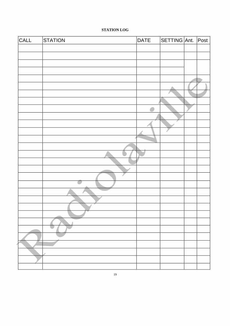
Station Log It is very interesting to keep a record of the
stations heard in somewhat the same manner as the "log" of a commercial radio station although not in so much detail.
For the convenience of our patrons, the last section of this Instruction Book is made up of special blank forms on which a record of stations heard may be kept and means are provided so that any station that has been heard can be easily and quickly found again whenever it is operating.
Pages 18 to 21 inclusive consist of sheets of a special blank form, designed for recording enough data about the adjustment of the apparatus when receiving signals from
each station to enable that adjustment to be duplicated at will. The first column of this form is intended to be filled in with the call letters of the station. Every radio station, licensed to transmit, has a sequence of three or four letters assigned to it, these letters acting like a complete name and address. All call letters beginning with "N" belong to stations of the United States Navy. Those beginning with "K" and "W" belong to Commercial stations, in which classification, broad-casting stations are included. Amateur calls begin with numbers, 1 to 9 inclusive, followed by two or three letters, the number indicating the section of the United States in
16

Radiola Grand Loud Speaking Radio Receiver
which the station is located. The second column is intended for the name and address -of the station. The third column is for the date. The fourth column is for the number on the tuner dial to which the handle points when the station is tuned to produce the greatest strength of signal. Since this point will vary slightly with other adjustments we suggest that all readings be taken with the Vernier pointing to "5" and with the tickler at "5". This will insure the same adjustments every time. The
column headed "A" is intended for a note showing which antenna is in use if two antennas are available. We suggest that "L" be used to designate the large, outdoor antenna for long distance work while "S" is used to designate the small, indoor antenna for nearby stations. The last column headed "P" is intended to show to which antenna post on the back of the RADIOLA GRAND the antenna was connected. Sample entries to show how the log is to be used are given below.
CALL
STATION
DATE
SETTING
Ant.
Post
KDKA
Westinghouse Electric & Mfg. Co., East 'Pittsburgh, Pa.
10-13-22
5.6
L
L
NOF
U. S. Navy Anacostia, Washington, D. C. ^ <,
10-13-22
7.6
L
L
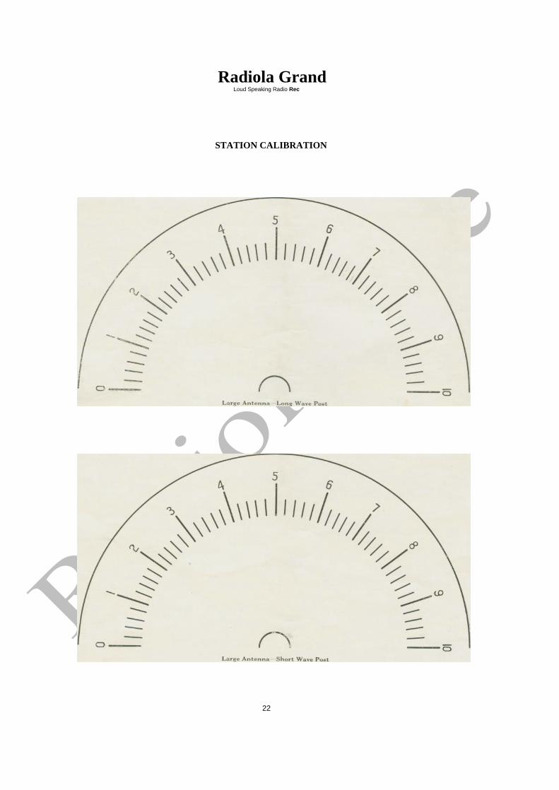
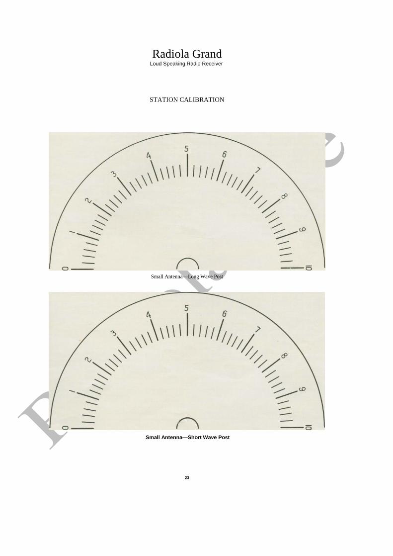
Station Calibration
Pages 22 and 23 are provided with four semi-circles representing the scale of the tuner dial on the RADIOLA GRAND. A separate chart is provided for each combination of antenna and antenna post. Record the stations heard by drawing arrowheads with station call letter marked on them as shown in fig. 11. This will act as an index of the stations so that the proper setting to receive any station may be found at a glance.
This record should be kept in pencil since the wave length, and hence the adjustment, of a station may be slightly changed from time to time and it is desirable to be able to correct this chart and keep it up to date. Of
course, if a change is made in the antenna or if the RADIOLA GRAND is moved to a new location, this
chart must be made over.
Wave Length Calibration Pages 24 and 25 are intended as a permanent
calibration of the RADIOLA GRAND for wavelength. It is impossible to do this until the set has been installed and connected for service. Two methods of calibration are available. The quickest method is to obtain a wavemeter and calibrate the set directly while connected to the antenna. This is often inconvenient so that the following method is suggested. Pick any one station say KDKA for instance, note the tuner setting as recorded in the "Station Log". Find a point on the proper chart corresponding to the antenna and antenna-post in use at the time, which bears the same number along the lower horizontal line as the tuner setting. Directly above this point at a height corresponding to the wave length of the same station, make a small cross. Do this for all the stations possible. When a sufficient number
of such points have been plotted, a smooth curve can be drawn through them. This chart will remain correct as long as the antenna is not materially altered. A word of caution about wave length is necessary. The proper wave length to use is not the nominal wave length which may have been published but the actual wave length which may be obtained from someone who has measured it.
If these various charts are properly filled out, the user of the RADIOLA GRAND will be able to quickly locate any station that has been heard before, the signals of which are coming in.
It is very interesting to see how many different stations can be heard, especially when the stations are several hundred miles away. For the assistance of our patrons, we are also supplying a map of the United States on which to mark the locations of the various stations.
17
Fig. 11

STATION LOG
CALL
STATION
DATE
SETTING
Ant.
Post
18
STATION LOG
CALL
STATION
DATE
SETTING
Ant.
Post
19

CALL
STATION
DATE
SETTING
Ant.
Post

STATION LOG
CALL
STATION
DATE
SETTING
Ant.
Post
21
Radiola Grand Loud Speaking Radio Rec
STATION CALIBRATION
22
Radiola Grand Loud Speaking Radio Receiver
STATION CALIBRATION
Small Antenna—Long Wave Post
Small Antenna—Short Wave Post
23

Radiola Grand Loud Speaking Radio Receiver
WAVE LENGTH CALIBRATION
Large Antenna—Long Wave Post
24

Radiola Grand Loud Speaking Radio Receiver
WAVE LENGTH CALIBRATION
300^—————
23456 56ttinq
Small Antenna—Long Wave Post
-7
8
9
10
25


INDEX Title Page No.
RECEIVERS
Introduction. ........................................................................... 3
Classes of Receivers.................................................................3—4
The Radiola Grand....................................................................4
EQUIPMENT
Standard Equipment...................................................................4
Additional Equipment Necessary...............................................4—5
Alternate and Extra Equipment..................................................5
Cabinet Receiver........................................................................5-6
INSTALLATION
Location..................................................................................... 6
Antenna.......................................................................................6
Antenna Package.........................................................................7
Underwriter's Rules...................................................................7-8
Antenna Connection....................................................................8
Ground Connection.....................................................................8
Connection of Filament or A Batteries.......................................8
Insertion of Tubes.......................................................................9
Cleaning of Cabinet....................................................................9
OPERATION
General.......................................................................................9
Controls and Tuning............................................................... 9-10
Hunting Signals.........................................................................10
Final Adjustment of Filament Rheostat....................................10
Regeneration.............................................................................11
Sound Volume Control.............................................................12
MAINTENANCE
General......................................................................................12
Renewal of Vacuum Tubes.......................................................12
Renewal of A Batteries.............................................................12
Renewal of B Batteries.............................................................13
Renewal of C Batteries............................................................13
Replacing Grid Leak Condenser. .............................................13
Renewal of Rubber Mountings. ...............................................13
Operating Troubles...................................................................13
THE ELECTRIC CIRCUIT
General................................................................................ 14 to 16
STATION LOG. .............................................……16, 17, 18 to 21
STATION CALIBRATION................................ …..17, 22-23
WAVE LENGTH CALIBRATION. ....................... 17, 24-25
RECEPTION MAP.................................................... 26
27