+ PROFIBUS - METAL WORK HDM + profibus.pdf · 20 HEAVY DUTY MULTIMACH + PROFIBUS TECHNICAL DATA The...
9
20 HEAVY DUTY MULTIMACH + PROFIBUS TECHNICAL DATA The HDM+PROFIBUS system has been designed in such a way that the pneumatic input terminal contains all the electronics, signals and connectors. It is a very compact and sturdy system where everything is housed in a thick casing aluminium to protect the delicate components against impact. The valves and accessories are HDM standard, which means that you only need to replace the input terminal to convert the valve island with multiple connector into an PROFIBUS island. All the advantages of the HDM system can be exploited: the possibility of mounting valves of different size, with fittings for pipes 4, 6 or 8; the insertion of intermediate modules with separate power supply or outlets; aluminium valves with chemical nickel plating enclosed in a protective casing in reinforced technopolymer, with an index of protection IP65. The arrangement of the functions continues the traditional optimisation of the HDM: the user interface of the valves and bus all on one side, so that the fitter and service engineer have everything within easy reach: all compressed air connections are on the other side, and the electrical connectors and selectors are at the end of the island. It is advisable to earth the system to prevent electrical or electrostatic discharge from damaging the electronic circuit. Valve port connections Connection on the end-plate 1-11 for the supply of pilots Maximum number of pilots Maximum number of valves Operating temperature range °C Fluid Flow rate at 6 bar ΔP 1bar Nl/min Pressure range - terminal 1-11 - terminal 1 Voltage range Power for each pilot W Solenoid Pilot Insulation class Degree of protection Solenoid rating TRA/TRR 2X3/2 monostable at 6 bar ms TRA/TRR 5/2 monostable at 6 bar ms TRA/TRR 5/2 bistable at 6 bar ms TRA/TRR 5/3 cc monostable at 6 bar ms Note on use Profibus DP module for HDM valves Protection Max input power (all valves ON) Addressing Highest settable address number Default address Peripheral defect diagnosis Defects reported Module status in the event of peripheral defect Data bit value Output status in the absence of communication Ø 4,6,8 mm fitting for ports 2 and 4 / Ø8 fitting for inlet port / thread 3/8 or Ø8 fitting for exhaust port Automatic fitting Ø 4 mm 16 16 (same as the max. no. of pilots) -10 ÷ +60 Filtered air without lubrication; lubrication, if used, must be continuous 11mm Ø 4 = 200 11mm Ø 6 = 500 14mm Ø 8 = 800 X (pilot supply) 1-11 (valve supply) 3 ÷ 7 bar vacuum at 10 bar 3 ÷ 7 bar 24 VDC ±10% (slave protected against overload and reverse polarity) 0,9 F155 IP65 (with conveyed exhust, and that - in case of no use - the BUS OUT connector gets plugged.) 100% ED 8 / 45 8 / 33 20 / 20 20 / 20 Insert the pipes in the fittings, before passing air through the valves, otherwise the gasket may be pulled out of its seat by the flow of air. For compatibility with oils, refer to the technical documentation – Section 6 Outputs protected against overloads and shortcircuits ˜ 500 mA By rotary selectors 99 3 Local LED indicator and relay to Master Output shortcircuit or overload. Auxiliary power supply failure. Profibus communication active. The “peripheral defect” bit is active and accessible at the master station. 0 = not enabled 1 = enabled Disabled
Transcript of + PROFIBUS - METAL WORK HDM + profibus.pdf · 20 HEAVY DUTY MULTIMACH + PROFIBUS TECHNICAL DATA The...
20
HEAVY DUTY MULTIMACH+ PROFIBUS
TECHNICAL DATA
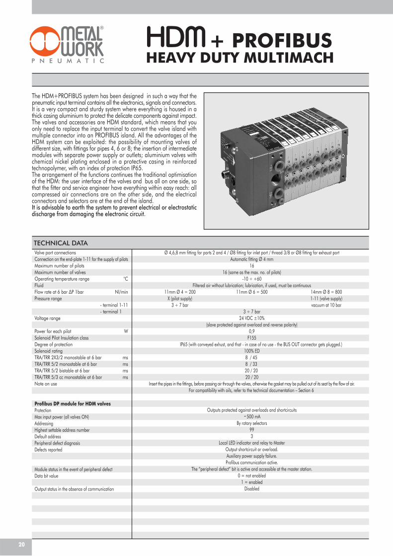
The HDM+PROFIBUS system has been designed in such a way that thepneumatic input terminal contains all the electronics, signals and connectors.It is a very compact and sturdy system where everything is housed in athick casing aluminium to protect the delicate components against impact.The valves and accessories are HDM standard, which means that youonly need to replace the input terminal to convert the valve island withmultiple connector into an PROFIBUS island. All the advantages of theHDM system can be exploited: the possibility of mounting valves ofdifferent size, with fittings for pipes 4, 6 or 8; the insertion of intermediatemodules with separate power supply or outlets; aluminium valves withchemical nickel plating enclosed in a protective casing in reinforcedtechnopolymer, with an index of protection IP65.The arrangement of the functions continues the traditional optimisationof the HDM: the user interface of the valves and bus all on one side, sothat the fitter and service engineer have everything within easy reach: allcompressed air connections are on the other side, and the electricalconnectors and selectors are at the end of the island.It is advisable to earth the system to prevent electrical or electrostaticdischarge from damaging the electronic circuit.
Valve port connectionsConnection on the end-plate 1-11 for the supply of pilotsMaximum number of pilotsMaximum number of valvesOperating temperature range °CFluidFlow rate at 6 bar ΔP 1bar Nl/minPressure range
- terminal 1-11- terminal 1
Voltage range
Power for each pilot WSolenoid Pilot Insulation classDegree of protectionSolenoid ratingTRA/TRR 2X3/2 monostable at 6 bar msTRA/TRR 5/2 monostable at 6 bar msTRA/TRR 5/2 bistable at 6 bar msTRA/TRR 5/3 cc monostable at 6 bar msNote on use
Profibus DP module for HDM valvesProtectionMax input power (all valves ON)AddressingHighest settable address numberDefault addressPeripheral defect diagnosisDefects reported
Module status in the event of peripheral defectData bit value
Output status in the absence of communication
Ø 4,6,8 mm fitting for ports 2 and 4 / Ø8 fitting for inlet port / thread 3/8 or Ø8 fitting for exhaust portAutomatic fitting Ø 4 mm
1616 (same as the max. no. of pilots)
-10 ÷ +60Filtered air without lubrication; lubrication, if used, must be continuous
11mm Ø 4 = 200 11mm Ø 6 = 500 14mm Ø 8 = 800X (pilot supply) 1-11 (valve supply)
3 ÷ 7 bar vacuum at 10 bar3 ÷ 7 bar
24 VDC ±10%(slave protected against overload and reverse polarity)
0,9F155
IP65 (with conveyed exhust, and that - in case of no use - the BUS OUT connector gets plugged.)100% ED8 / 458 / 3320 / 2020 / 20
Insert the pipes in the fittings, before passing air through the valves, otherwise the gasket may be pulled out of its seat by the flow of air.For compatibility with oils, refer to the technical documentation – Section 6
Outputs protected against overloads and shortcircuits
˜500 mABy rotary selectors
993
Local LED indicator and relay to MasterOutput shortcircuit or overload.Auxiliary power supply failure.Profibus communication active.
The “peripheral defect” bit is active and accessible at the master station.0 = not enabled
1 = enabledDisabled
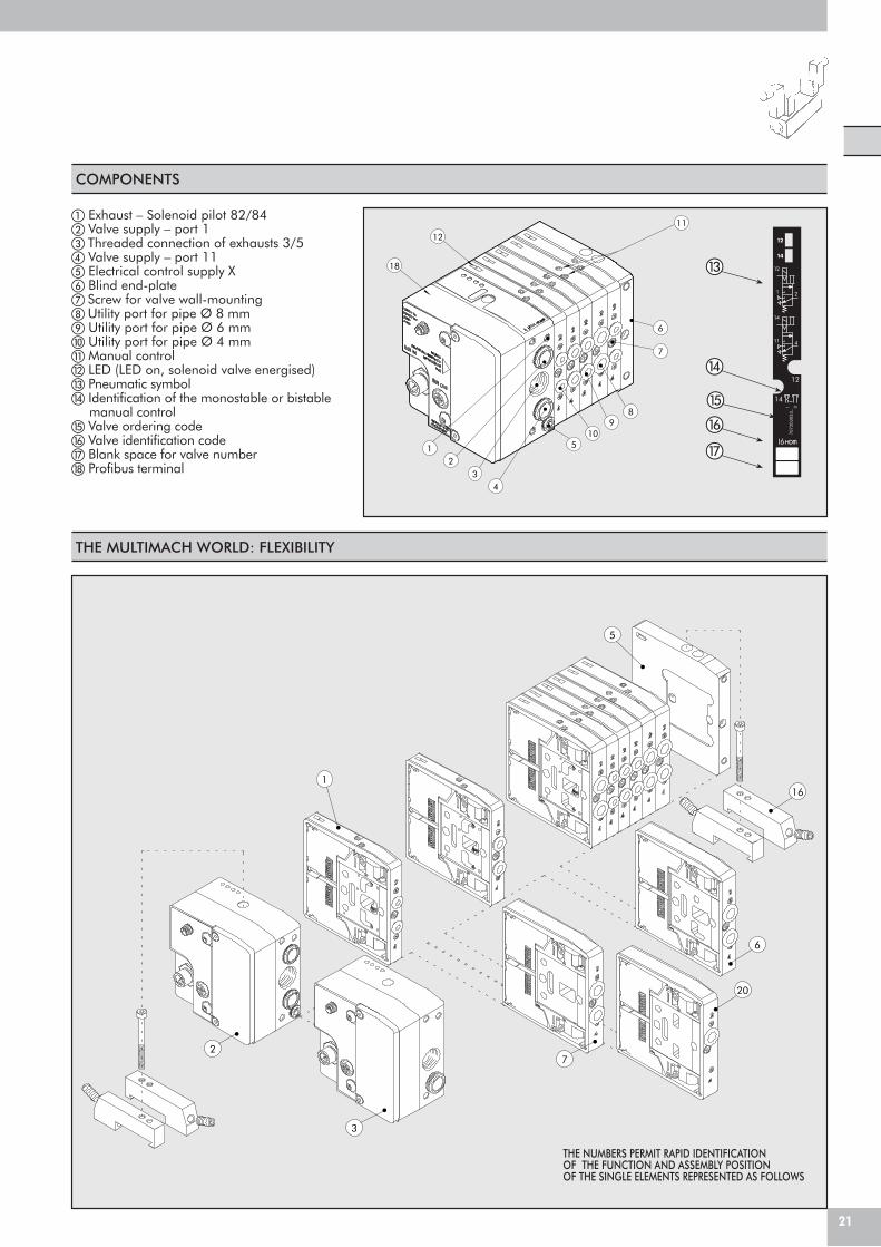
COMPONENTS
� Exhaust – Solenoid pilot 82/84� Valve supply – port 1� Threaded connection of exhausts 3/5� Valve supply – port 11� Electrical control supply X� Blind end-plate� Screw for valve wall-mounting Utility port for pipe Ø 8 mm Utility port for pipe Ø 6 mm� Utility port for pipe Ø 4 mm� Manual control LED (LED on, solenoid valve energised)� Pneumatic symbol� Identification of the monostable or bistable
manual control� Valve ordering code� Valve identification code� Blank space for valve number� Profibus terminal
THE MULTIMACH WORLD: FLEXIBILITY
7
20
5
161
6
3
2
THE NUMBERS PERMIT RAPID IDENTIFICATIONOF THE FUNCTION AND ASSEMBLY POSITIONOF THE SINGLE ELEMENTS REPRESENTED AS FOLLOWS
21
11
18
510
98
7
6
12
43
12
�
�
�
�
�
12
14
7072
0305
3_1 0
14
12
I6
12
1 2
14
11 4
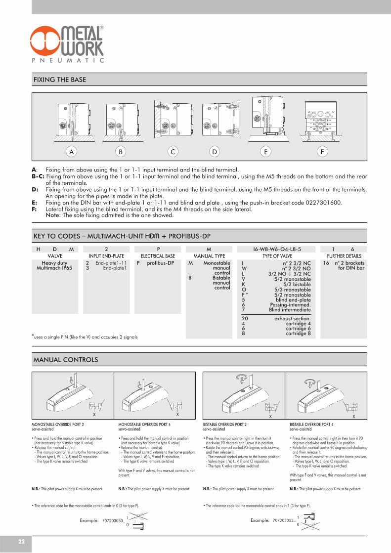
FIXING THE BASE
A: Fixing from above using the 1 or 1-1 input terminal and the blind terminal.B-C: Fixing from above using the 1 or 1-1 input terminal and the blind terminal, using the M5 threads on the bottom and the rear
of the terminals.D: Fixing from above using the 1 or 1-1 input terminal and the blind terminal, using the M5 threads on the front of the terminals.
An opening for the pipes is made in the plate.E: Fixing on the DIN bar with end-plate 1 or 1-11 and blind and plate , using the push-in bracket code 0227301600.F: Lateral fixing using the blind terminal, and its the M4 threads on the side lateral.
Note: The sole fixing admitted is the one showed.
A DCB E F
MANUAL CONTROLS
MONOSTABLE OVERRIDE PORT 2servo-assisted
• Press and hold the manual control in position(not necessary for bistable type K valve)
• Release the manual control:- The manual control returns to the home position.
- Valves type I, W, L, V, F, and O reposition.- The type K valve remains switched
N.B.: The pilot power supply X must be present.
MONOSTABLE OVERRIDE PORT 4servo-assisted
• Press and hold the manual control in position(not necessary for bistable type K valve)
• Release the manual control:- The manual control returns to the home position.- Valves type I, W, L, V and F reposition.- The type K valve remains switched
With type F and V valves, this manual control is notpresent.
N.B.: The pilot power supply X must be present.
BISTABLE OVERRIDE PORT 2servo-assisted
• Press the manual control right in then turn itclockwise 90 degrees and Leave it in position.
• Rotate the manual control 90 degrees anticlockwise,and then release it.- The manual control returns to the home position.- Valves type I, W, L, V, F, and O reposition.- The type K valve remains switched
N.B.: The pilot power supply X must be present.
BISTABLE OVERRIDE PORT 4servo-assisted
• Press the manual control right in then turn it 90 degrees clockwise and Leave it in position.
• Rotate the manual control 90 degrees anticlockwise,and then release it:- The manual control returns to the home position.- Valves type I, W, L and O reposition.- The type K valve remains switched
With type F and V valves, this manual control is notpresent.
N.B.: The pilot power supply X must be present.
Example: 707203053_ 1
0707203053_ 1
0Example:
• The reference code for the monostable control ends in 0 (2 for type F). • The reference code for the monostable control ends in 1 (3 for type F).
KEY TO CODES – MULTIMACH-UNIT + PROFIBUS-DP
H D M
Heavy dutyMultimach IP65
2
2 End-plate1-113 End-plate1
VALVE INPUT END-PLATEP
P profibus-DPELECTRICAL BASE
I6-W8-W6-O4-L8-5TYPE OF VALVE
1 6FURTHER DETAILS
16 n° 2 brackets for DIN bar
M
M Monostablemanualcontrol
B Bistable manual
control
MANUAL TYPE
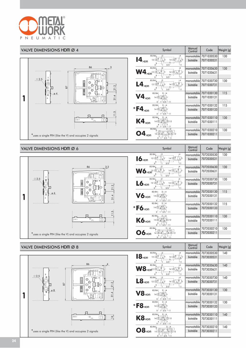
*uses a single PIN (like the V) and occupies 2 signals
I n° 2 3/2 NCW n° 2 3/2 NOL 3/2 NO + 3/2 NCV 5/2 monostableK 5/2 bistableO 5/3 monostableF 5/2 monostable5 blind end-plate6 Passing-intermed.7 Blind intermediate
20 exhaust section.4 cartridge 46 cartridge 68 cartridge 8
*
22
XX XX
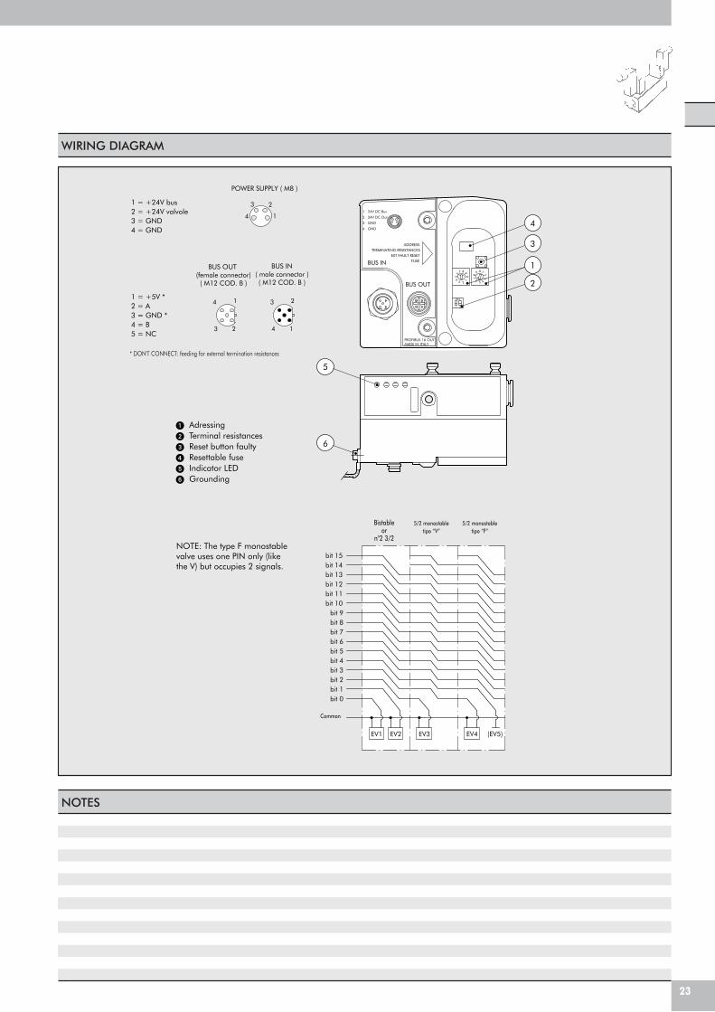
WIRING DIAGRAM
NOTES
23
bit 14
bit 0
EV2 EV3EV1
bit 6bit 5bit 4bit 3bit 2bit 1
bit 15
bit 9
bit 7bit 8
bit 10bit 11bit 12bit 13
EV4 (EV5)
PROFIBUS 16 OUTMADE IN ITALY
BUS OUT
ADDRESSTERMINATING RESISTANCES
EXT FAULT RESETFUSEBUS IN
4
2
3
1
5
6
ON
1 24V DC Bus
2 24V DC Out
3 GND
4 GND
1 2
19 0
28
3
4
7
561
9
0
2
8
34
7
56
41 = +5V *2 = A3 = GND *4 = B5 = NC
2
14
31 = +24V bus2 = +24V valvole3 = GND4 = GND
BUS OUT (female connector)( M12 COD. B )
BUS IN( male connector )( M12 COD. B )
3 2
1 3
4
2
1
Bistableor
n°2 3/2
5/2 monostabletipo “V”
5/2 monostabletipo “F”
Common
POWER SUPPLY ( M8 )
NOTE: The type F monostablevalve uses one PIN only (likethe V) but occupies 2 signals.
� Adressing� Terminal resistances� Reset button faulty� Resettable fuse� Indicator LED� Grounding
* DON'T CONNECT: feeding for external termination resistances
82/84
X 111 3/5
1412
2 4
3/5
82/84
X 111
12
2 4
14
3/5
82/84
X 111
1412
42
14
82/84 2 4
3/5X 1 11
82/84 2
X 1
4
113/5
14 12
3/5X 11
82/84 2
1
4
14 12
82/84
X 111 3/5
1412
2 4
3/5
82/84
X 111
12
2 4
14
3/5
82/84
X 111
1412
42
14
82/84 2 4
3/5X 1 11
82/84 2
X 1
4
113/5
14 12
3/5X 11
82/84 2
1
4
14 12
82/84
X 111 3/5
1412
2 4
3/5
82/84
X 111
12
2 4
14
3/5
82/84
X 111
1412
42
14
82/84 2 4
3/5X 1 11
82/84 2
X 1
4
113/5
14 12
3/5X 11
82/84 2
1
4
14 12
I6
W6
L6
V6
F6
K6
O6
I8
W8
L8
V8
F8
K8
O8
VALVE DIMENSIONS Ø 4
ø 4
2.5
31.4
87
21.2
11.5
86 3
VALVE DIMENSIONS Ø 6
ø 6
2.5
3.2
11.5
86
21.2
31.4
ø 8
2.5
4
14
86
21.287
31.4
Symbol
Symbol
SymbolVALVE DIMENSIONS Ø 8
1
1
1
I4
W4
L4
V4
F4
K4
O4
Code
70710305307071030531
70710306307071030631
70710307307071030731
70710301307071030131
70710301327071030133
70710301107071030111
70710302107071030211
ManualControl
monostablebistable
monostablebistable
monostablebistable
monostablebistable
monostablebistable
monostablebistable
monostablebistable
14
82/84 2 4
3/5X 1 11
Code
70720305307072030531
70720306307072030631
70720307307072030731
70720301307072030131
70720301327072030133
70720301107072030111
70720302107072030211
ManualControl
monostablebistable
monostablebistable
monostablebistable
monostablebistable
monostablebistable
monostablebistable
monostablebistable
14
82/84 2 4
3/5X 1 11
Code
70730305307073030531
70730306307073030631
70730307307073030731
70730301307073030131
70730301327073030133
70730301107073030111
70730302107073030211
ManualControl
monostablebistable
monostablebistable
monostablebistable
monostablebistable
monostablebistable
monostablebistable
monostablebistable
14
82/84 2 4
3/5X 1 11
*uses a single PIN (like the V) and occupies 2 signals
*uses a single PIN (like the V) and occupies 2 signals
*uses a single PIN (like the V) and occupies 2 signals
*
*
*
Weight [g]
130
130
130
115
115
130
130
Weight [g]
130
130
130
115
115
130
130
Weight [g]
140
140
140
130
130
140
140
24
M 5x9
G 3/8M 12
M 8
3/5
82/84
ø 4
M 5
M 5x9
M 5x9
1
11
X
M 5x9
ø 10
ø 10
76.5
64.2
43.7
10 9.723
.2 34.5
ø 4.2M 5
2.9
9
86.1
8088.8
19
13
6
10.56
14
5345.6
1080
13
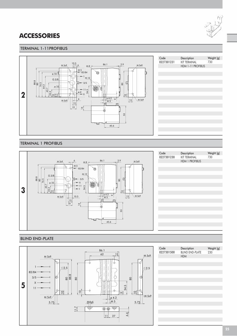
ACCESSORIES
TERMINAL 1-11PROFIBUS
Code0227301231
DescriptionKIT TERMINALHDM 1-11 PROFIBUS
TERMINAL 1 PROFIBUS
Code0227301230
DescriptionKIT TERMINALHDM 1 PROFIBUS
M 5x9
82/84
3/5
M 12
M 5
1
X
G 3/8
ø 10
M 5x9
M 5x9
11
M 8 M 5x9
45.6
76.5
10
80
23.2
53
43.7
13
88.8
8010
86.1
14
10.5
13
6
9
2.9
M 5ø 4.2
19
34.5
BLIND END-PLATE
2.5
M 5x9
M 5x9
2.5
M 5x9
M 5x9
82/84
3/5
11
1
X
6.6
M 5ø 4.2
11.7
2711
10
80
10 934
.5
5.75
86.1
80
M4x6
62 12
5.75
10
80 88.8
5
Code0227301500
DescriptionBLIND END-PLATEHDM
Weight [g]230
2
3
25
Weight [g]730
Weight [g]730
ø 8
3/5
X82/84
2.5
111
ø 8
87
86 4
21.2
31.4
14
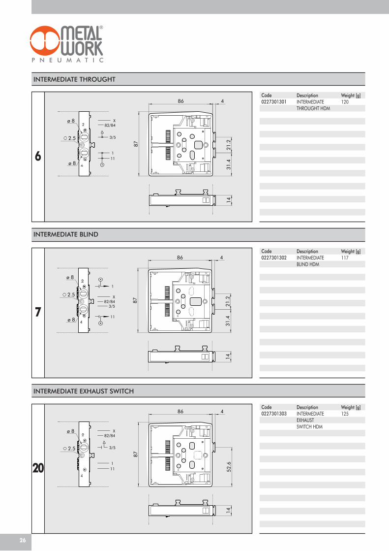
INTERMEDIATE THROUGHT
Code0227301301
DescriptionINTERMEDIATETHROUGHT HDM
INTERMEDIATE BLIND
6
ø 8
ø 8
3/582/84
X
11
1
2.5
87
86 4
21.2
31.4
14
7
Code0227301302
DescriptionINTERMEDIATEBLIND HDM
Weight [g]120
Weight [g]117
INTERMEDIATE EXHAUST SWITCH
ø 8
3/5
X82/84
111
2.5
4
52.6
87
86
14
20
Code0227301303
DescriptionINTERMEDIATEEXHAUSTSWITCH HDM
Weight [g]125
26
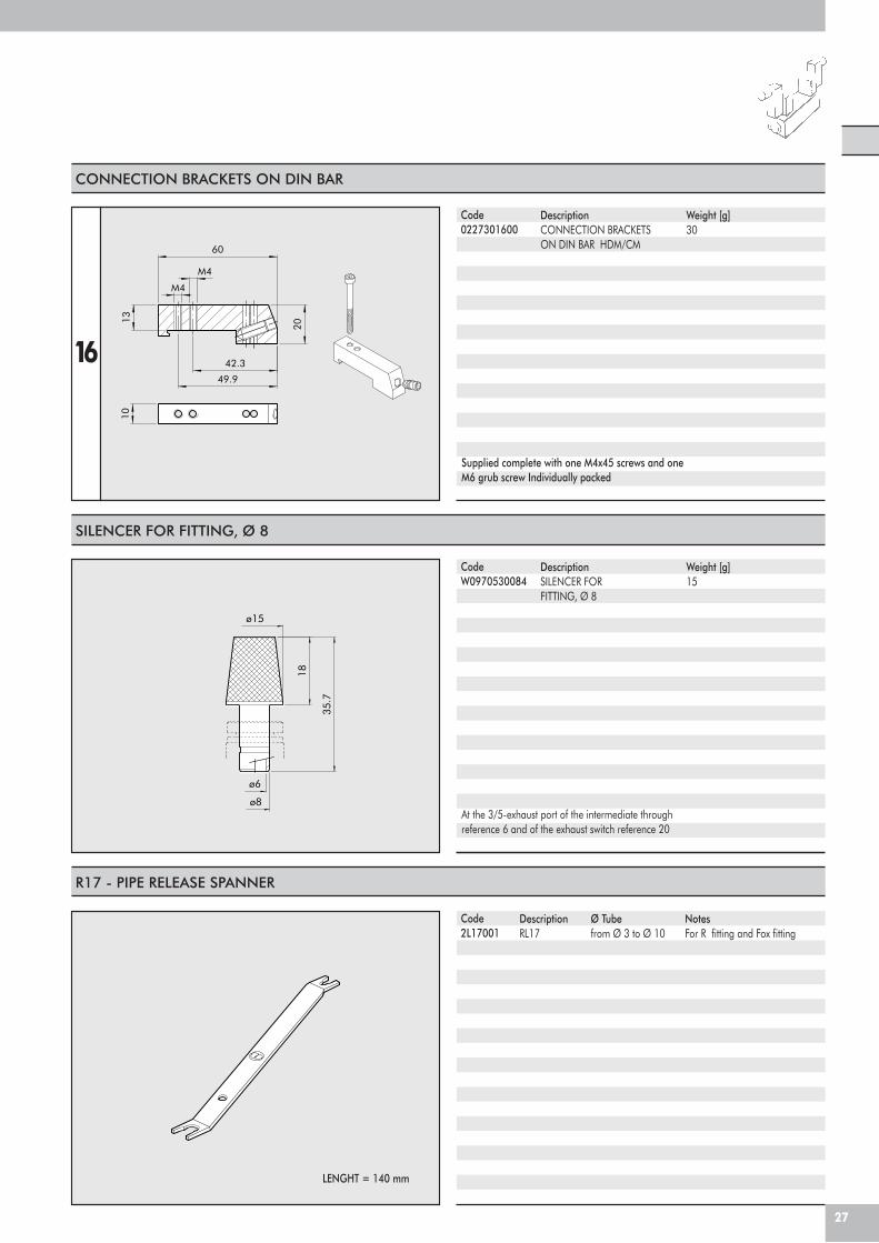
CONNECTION BRACKETS ON DIN BAR
Code0227301600
DescriptionCONNECTION BRACKETSON DIN BAR HDM/CM
16
Supplied complete with one M4x45 screws and oneM6 grub screw Individually packed
Weight [g]30
SILENCER FOR FITTING, Ø 8
CodeW0970530084
DescriptionSILENCER FORFITTING, Ø 8
At the 3/5-exhaust port of the intermediate throughreference 6 and of the exhaust switch reference 20
Weight [g]15
R17 - PIPE RELEASE SPANNER
Code2L17001
DescriptionRL17
LENGHT = 140 mm
Ø Tubefrom Ø 3 to Ø 10
NotesFor R fitting and Fox fitting
27
ø15
ø8
18
35.7
ø6
13
20
M4
M4
60
42.3
49.9
10
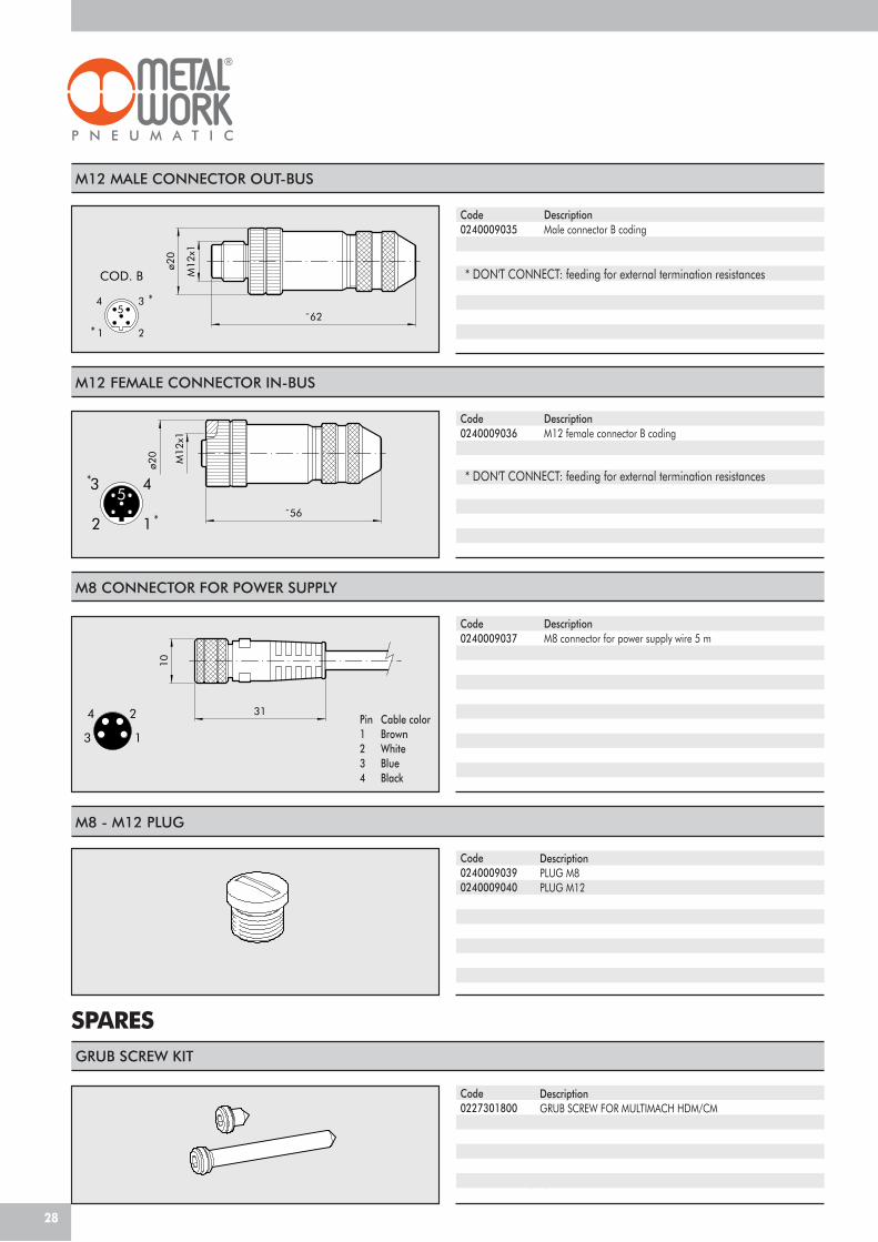
M8 - M12 PLUG
Code02400090390240009040
DescriptionPLUG M8PLUG M12
COD. B
4
2
3
1
5
2
34
1
5˜62
M12
x1
ø20
M12 MALE CONNECTOR OUT-BUS
Code Description0240009035 Male connector B coding
4
3 1
2 31
10
M8 CONNECTOR FOR POWER SUPPLY
Code Description0240009037 M8 connector for power supply wire 5 m
Cable colorBrownWhiteBlueBlack
Pin1234
GRUB SCREW KIT
Code0227301800
DescriptionGRUB SCREW FOR MULTIMACH HDM/CM
SPARES
Comes in 1+1 pc. packs
28
M12 FEMALE CONNECTOR IN-BUS
53 4
2 1
M12
x1
˜56
ø20
Code Description0240009036 M12 female connector B coding
* DON'T CONNECT: feeding for external termination resistances
*
*
*
* * DON'T CONNECT: feeding for external termination resistances