Practical Analysis of Non-Termination in Large Logic Programs

Today
• Practical issues in digital logicimplementation
• Project 1

Administrivia
Make sure you fill out and hand-in groupplacement forms today

Solderless Breadboards
Ground bus
(blue)Component
bus
Power bus(red)
Note that the twosides are notconnected
mbus.net

Wiring Standards
When possible, use wire colors for differenttypes of signals:
• Black: ground
• Red: power
• Other: various signals

Clean WiringA clean breadboard will make debugging
easier – and it makes circuits more robust
www.linefollowing.com
tangentsoft.net

Care with Power
• Only insert components and wires into thebreadboard when power is disconnected
• “Wire, check-twice, then power”– Never reverse power and ground (this is a
very common mistake)
• Most chips that we will use expect +5V– More can destroy the chips– We will use DC/DC converters to step battery
voltages down to +5V

Care of Chips
• Use insertion and extraction tools: neveryour fingers
• Minimize your contact with pins: staticelectricity can destroy a chip
• Use a wrist strap when you handle chips
www.a7vtroubleshooting.comwww.chantronics.com.au
www.hvwtech.com

TTL Chips: 2-Input AND Gates
Chip number: 7408
www.dcs.warwick.ac.uk www2.117.ne.jp
Power
Pin 1 ismarkedon thechip
Ground

TTL Chips: 2-Input OR/XOR Gates
7432 or 74LS32
www.dcs.warwick.ac.uk
7486 or 74LS86

TTL Chips: 3-Input AND Gates
digikey.com
7411

Constant Inputs
How do we configure a chip input as aconstant?

Constant Inputs
How do we configure a chip input as aconstant?
• For a constant 0: connect to ground
• For a constant 1: use a pull-up resistor to+5V (e.g., 10K ohm)

Wiring Procedure (Suggested)
• Power supply
• Power/ground buses
• Insert primary components
• Wire power/ground for components
• Add signals and remaining components
• Test incrementally

Debugging Techniques• Multimeter:
– Use voltage mode to check logic levels
– Use continuity mode to confirm connections (butnever with power turned on)
• Oscilloscope:– View voltage as a function of time on 2 channels
– Locked in my office (Mark or I can retrieve them onrequest)
• Test incrementally
• Test intermediate sub-circuits

Debugging Techniques
Wire in LED to indicate logiclevel on a line
• For most components, donot allow the line to bedriven by more than 20mA(check the specs if in doubt)
• Note that in this circuit, theLED turns on when logiclevel is LOW
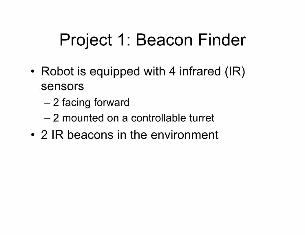
Project 1: Beacon Finder
• Robot is equipped with 4 infrared (IR)sensors– 2 facing forward
– 2 mounted on a controllable turret
• 2 IR beacons in the environment

Project 1: Beacon Finder
Task:
• Robot starts by approximately facing onebeacon
• Robot must turn to face beacon and thenmove toward it
• When the robot “sees” the second beaconto the left, the robot must stop
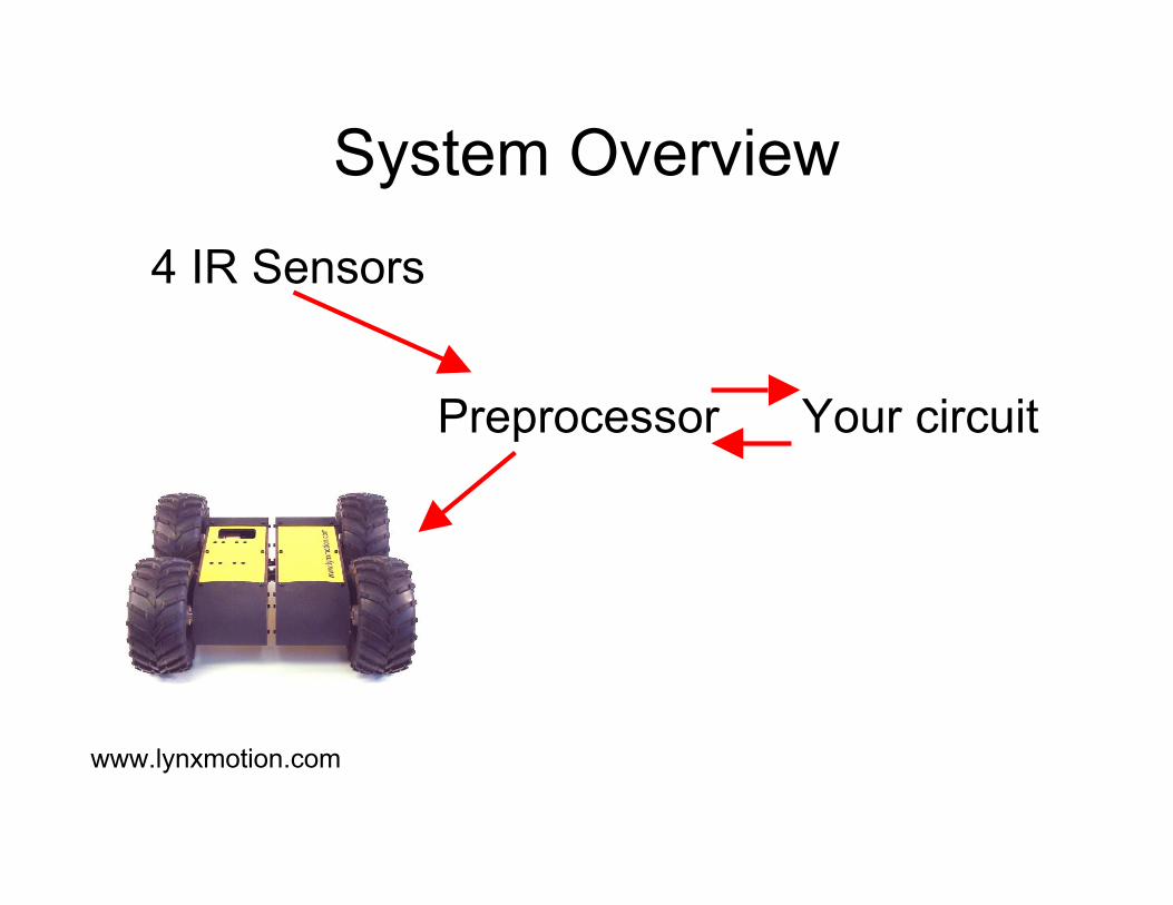
System Overview
www.lynxmotion.com
4 IR Sensors
Preprocessor Your circuit

Last Time
• Demultiplexers
• Tristate buffers
• Digital logic in practice
• Project 1

Today
• Finish off on project 1 (including ademonstration)
• Sequential logic:– Latches
– Flip-flips

Administrivia
Mark (our TA) is out of town until Tuesday.The lab is still open starting today:– 10:30-12:30
– 1-1:45
– 4:30-5:00
Hours next week should be as alreadydiscussed

Group Assignments
Group 1:• Barby• Carter• Park• HooverGroup 2:• Johnson• Greco• Schmidt• Gunter
Group 3:• Cohen• Littlefield• Culbreath• PowersGroup 4:• Lewis• Williams• Houck• Blanton
Group 5:• Tope• Moore• Watters• Sartin

Beacon ReceiverThe preprocessor translates the IR sensor signal
into a 2-bit number
The state of each IR sensor is encoded with itsown pair of bits
Strong signal11
Medium signal01
Low signal10
No signal00
SemanticsB0B1

Robot Details
Preprocessor
DC motor driver
Turret motor Serial-to-PWM

Robot Control Interface
3 output lineswilldeterminethe motionof the robot
x111
Backward011
Forward-Right101
Forward-Left001
Right110
Left010
Forward100
Stop000
SemanticsC0C1C2

Robot Control Interface
2 outputlines willdeterminethe turretposition
x11
Right01
Left10
Forward00
SemanticsT0T1

Your Job
Design and build a controller from basiclogic gates
• Design the function: given each possibleinput from the sensors, what should therobot do?
• For each of these cases what commandmust you generate?
• What circuit will generate this command?• Build the circuit

Hints
• A 7-chip design exists for this circuit
• The preprocessor includes LEDs thatenable you to see its inputs and outputs
• Do not underestimate the amount of timerequired to implement and debug yourcircuit

Hints
• Secure wires before running the robot
• Make sure that you connect batteriesproperly and that you bring power to yourcircuit

Power
We will use 2 batteries:• 7.2V for the DC motors• 9V for the control electronics
– The preprocessor circuit will step this down to5V and provide it to your circuit
• Never short power and ground!• Make sure you place used batteries in the
appropriate boxes for recharging

What You Turn In
• Be prepared to demonstrate in class on Tuesday,March 1st– You may demo to Mark or me at any time prior to this
class
• Project report:– Describe the function that you have implemented
– K-Maps
– Circuit design
• Personal report

Debugging/Safety Hints
• Start by testing your circuit prior to connectingmotor power
• Once you connect motor power, put your robotup “on blocks” before running it on the floor
• Move a beacon around the robot to confirm thatit performs appropriately
• Make sure you wire into your circuit the followingrule:– If no beacon signal, then stop the motion of the robot

Lab Procedures
• No food or drink are allowed in the lab.
• Before leaving the lab, please be sure to cleanup your workspace.
• Because some equipment may be in shortsupply, please coordinate with others who willneed these resources
• Never place dead components back into thestock (instead – place them in the ‘graveyard’)
Lab Procedures
• No equipment or supplies may leave the labwithout the permission of the monitor.
• No books may leave the lab.
• Please clear all guests with the lab monitor.
• Unless you have prior permission, please do nothandle the projects of other class members.

Lab Procedures
• Always check your wiring before you power up yourcircuit (especially your power and ground connections).
• When removing chips from breadboards, always use anappropriate tool (not your fingers!).
• If you break something, please report it (don't just put itaway).
• You are expected to supply and configure your ownlaptop computers for project use

Schedule
• We currently have 1 robot up and running– groups will need to share– The robots are designed so that you will be
able to easily remove your circuit whileleaving the other components intact
• We will soon have one robot for eachgroup (but be patient)

Next Time
Sequential logic: time and memory
• Readings:– ESP 2.4
– Sequential logic pages from playhookey.com