| PAGE 1 LCWS14 October 7 th 2014 CEA EXPERTISE WITH VERTICAL ELECTROPOLISHING (VEP) F. Eozénou.
21
| PAGE 1 LCWS14 October 7 th 2014 CEA EXPERTISE WITH VERTICAL ELECTROPOLISHING (VEP) F. Eozénou
-
Upload
taniya-merrifield -
Category
Documents
-
view
213 -
download
0
Transcript of | PAGE 1 LCWS14 October 7 th 2014 CEA EXPERTISE WITH VERTICAL ELECTROPOLISHING (VEP) F. Eozénou.

| PAGE 1
LCWS14 October 7th 2014
CEA EXPERTISE WITH VERTICAL ELECTROPOLISHING (VEP)
F. Eozénou

ELECTROPOLISHING AT CEA/IRFU: 2004-2014
Best Results for Q0 = f(Eacc) Curves Obtained for S0 program.
Recipe: EP 30 µm + 30' Ethanol Rinsing. 1DE1 and 1DE3 Cavities.
1,E+09
1,E+10
1,E+11
0 5 10 15 20 25 30 35 40 45 50
Eacc (MV/m)
Q0
1DE1 1st Seq (D)
1DE1 2d Seq (D)
1DE1 + HPR (S)
1DE1 3d Seq (S)
1DE3 1st Seq (D)
1DE3 2d Seq (S)
1Cell Horizontal EP: 2006-2009• Achievement of high gradients• Alternative recipe tested• Low voltage EP
Design and operation of a Vertical EP system: 2009-…• Operating since 2011• Optimization on 1Cell cavities• Operation with ILC and SPL cavities
EP on samples (CARE program): 2004-2006• Parameters optimization• Understanding of the process (F- diffusion)• Study of the aging of electrolytes• Sulfur contamination
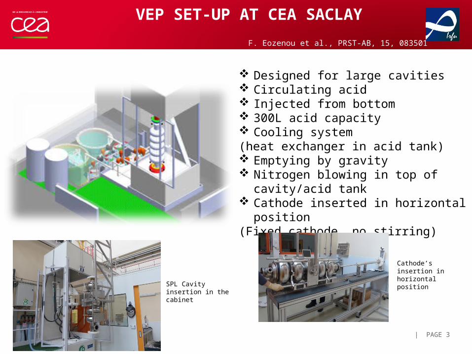
VEP SET-UP AT CEA SACLAY
| PAGE 3
Designed for large cavities Circulating acid Injected from bottom 300L acid capacity Cooling system (heat exchanger in acid tank) Emptying by gravity Nitrogen blowing in top of cavity/acid tank Cathode inserted in horizontal position(Fixed cathode, no stirring)
Cathode’s insertion in horizontal position
SPL Cavity insertion in the cabinet
F. Eozenou et al., PRST-AB, 15, 083501 (2012) (2012)
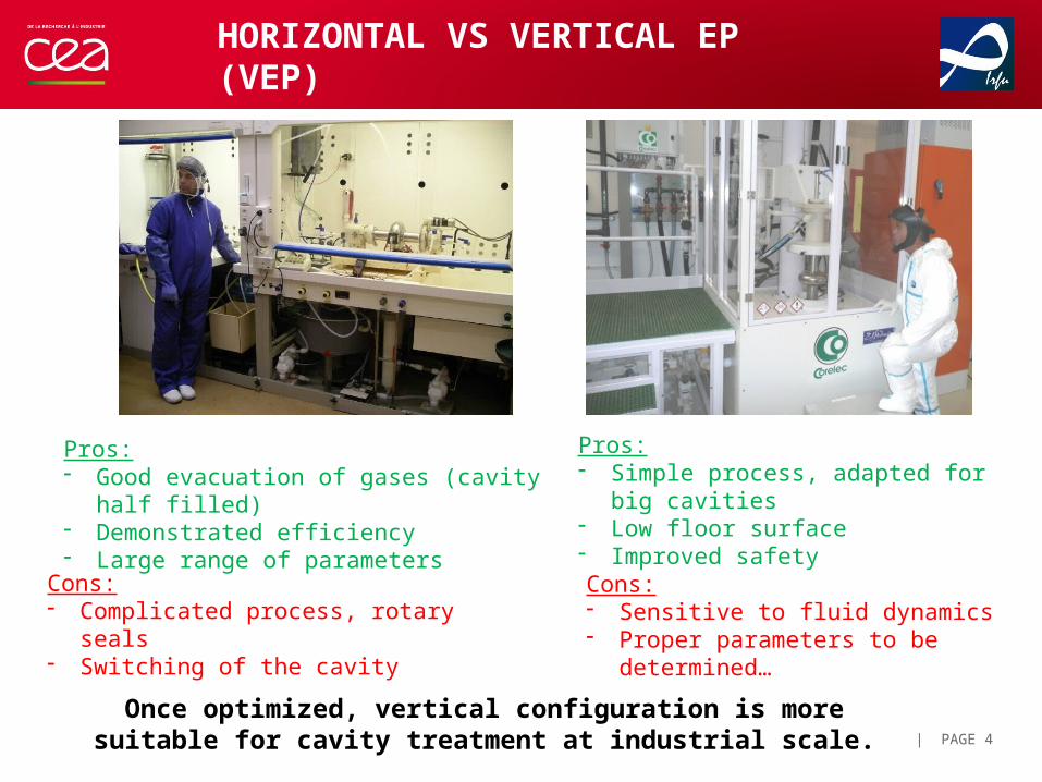
HORIZONTAL VS VERTICAL EP (VEP)
| PAGE 4
Pros:- Good evacuation of gases (cavity half filled)- Demonstrated efficiency- Large range of parameters
Cons:- Complicated process, rotary seals- Switching of the cavity
Pros:- Simple process, adapted for big cavities- Low floor surface- Improved safety
Cons:- Sensitive to fluid dynamics- Proper parameters to be determined…
Once optimized, vertical configuration is more suitable for cavity treatment at industrial scale.
| PAGE 5
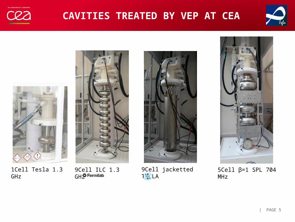
CAVITIES TREATED BY VEP AT CEA
1Cell Tesla 1.3 GHz 9Cell ILC 1.3 GHz 9Cell jacketted TESLA 5Cell β=1 SPL 704 MHz
| PAGE 6
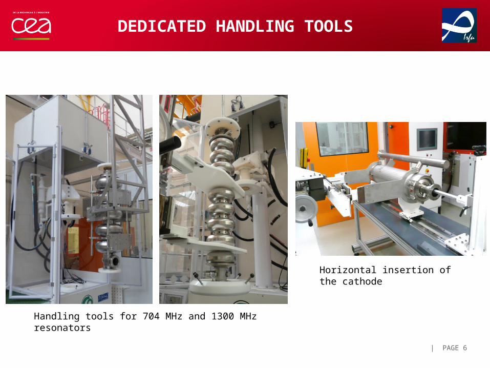
DEDICATED HANDLING TOOLS
Horizontal insertion of the cathode
Handling tools for 704 MHz and 1300 MHz resonators

| PAGE 7
VEP PARAMETERS
The choice for appropriate parameters is vital for efficient VEP
Set of parameters derived from Horizontal EP process is not recommended… Example: VEP at 10 V and 30 °C
Bubble traces
Pitting
Bright Surface
Strong assymetry. The local removal rate at pitting area is very high: ~ 1µm/min
| PAGE 8
MAIN CHALLENGES OF VEP PROCESS
• Efficient hydrogen outgassing
• Temperature control of the process
• Asymmetry of the process to overcome?
Temperature - Voltage relation in SPL caseU = 7.5 V ∆T < 1°C (acid temperature rise between bottom and top)U = 10 V ∆T > 4°C
9
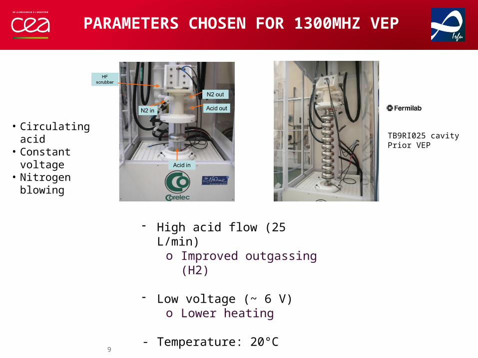
PARAMETERS CHOSEN FOR 1300MHZ VEP
- High acid flow (25 L/min)o Improved outgassing (H2)
- Low voltage (~ 6 V)o Lower heating
- Temperature: 20°C
TB9RI025 cavityPrior VEP
• Circulating acid• Constant voltage• Nitrogen blowing
MOTIVATION FOR EP AT LOW-VOLTAGE
| PAGE 10
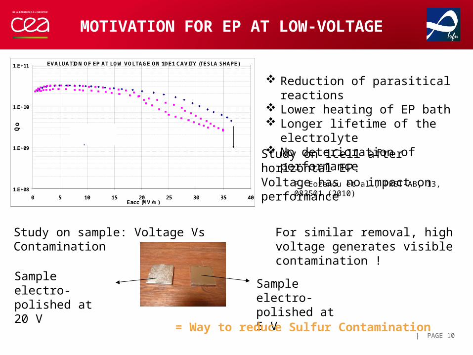
Sample electro-polished at 20 V
Sample electro-polished at 5 V
= Way to reduce Sulfur Contamination
EVALUATION OF EP AT LOW VOLTAGE ON 1DE1 CAVITY (TESLA SHAPE)
1.E+08
1.E+09
1.E+10
1.E+11
0 5 10 15 20 25 30 35 40Eacc (MV/m)
Qo
QUENCH
Standard EP
+ 90 µm at 5V
Reduction of parasitical reactions Lower heating of EP bath Longer lifetime of the electrolyte No deterioration of performance
F. Eozenou et al., PRST-AB, 13, 083501 (2010)
Study on 1Cell after horizontal EP:Voltage has no impact on performance
Study on sample: Voltage Vs Contamination For similar removal, high voltage generates visible contamination !
| PAGE 11
CHOICE OF THE CATHODE: ROD Vs SHAPED
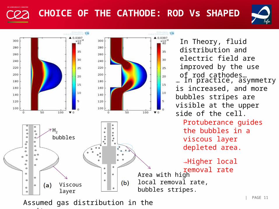
In Theory, fluid distribution and electric field are improved by the use of rod cathodes…
… In practice, asymmetry is increased, and more bubbles stripes are visible at the upper side of the cell.
H2 bubbles
Viscous layer
Area with high local removal rate, bubbles stripes.
Assumed gas distribution in the cavity
Protuberance guides the bubbles in a viscous layer depleted area.
→Higher local removal rate
| PAGE 12
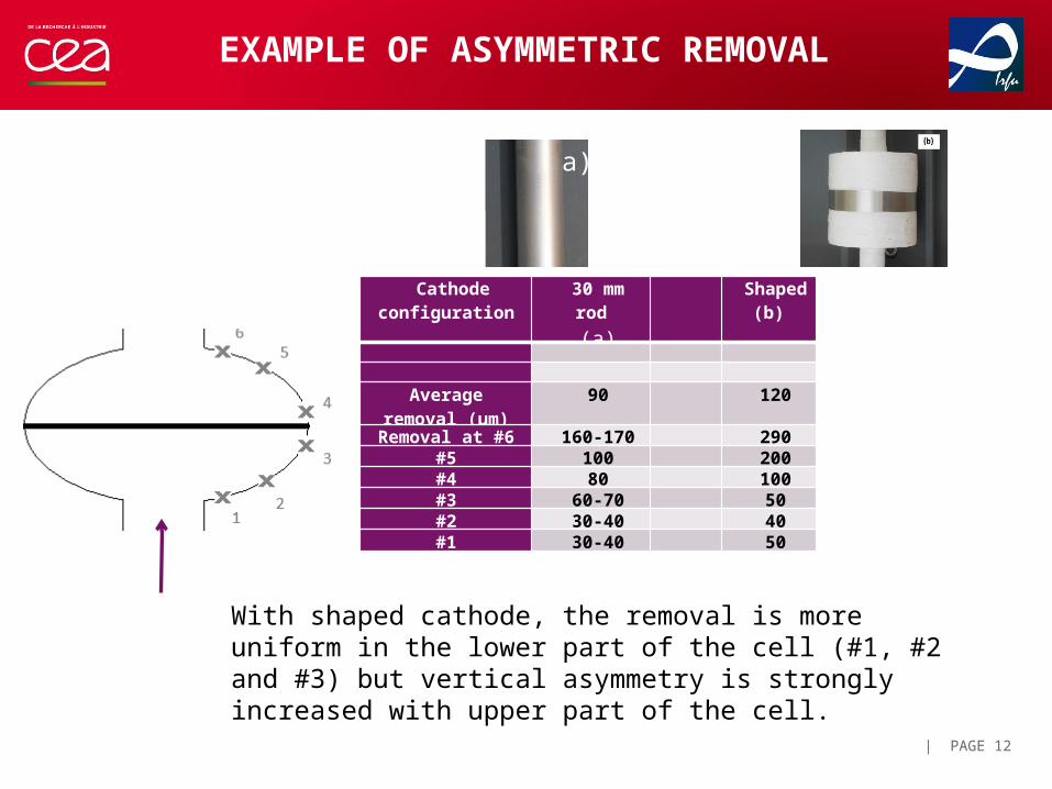
EXAMPLE OF ASYMMETRIC REMOVAL
Cathode configuration
30 mm rod(a)
Shaped (b)
Average removal (µm)
90 120
Removal at #6 160-170 290#5 100 200#4 80 100#3 60-70 50#2 30-40 40#1 30-40 50
a)
With shaped cathode, the removal is more uniform in the lower part of the cell (#1, #2 and #3) but vertical asymmetry is strongly increased with upper part of the cell.
| PAGE 13
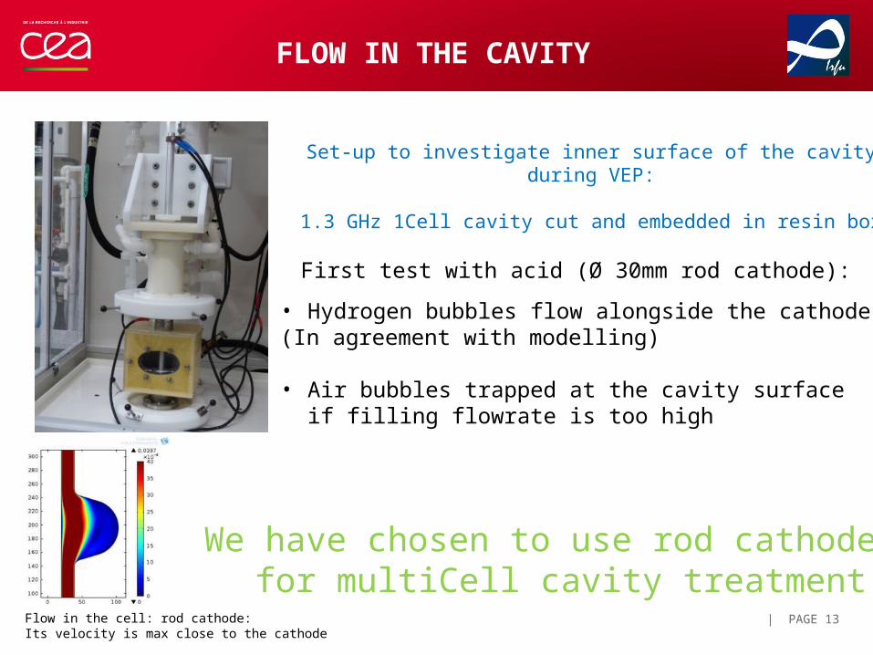
Set-up to investigate inner surface of the cavity during VEP:
1.3 GHz 1Cell cavity cut and embedded in resin box
First test with acid (Ø 30mm rod cathode):
• Hydrogen bubbles flow alongside the cathode(In agreement with modelling)
• Air bubbles trapped at the cavity surface if filling flowrate is too high
FLOW IN THE CAVITY
We have chosen to use rod cathodes for multiCell cavity treatment
Flow in the cell: rod cathode:Its velocity is max close to the cathode
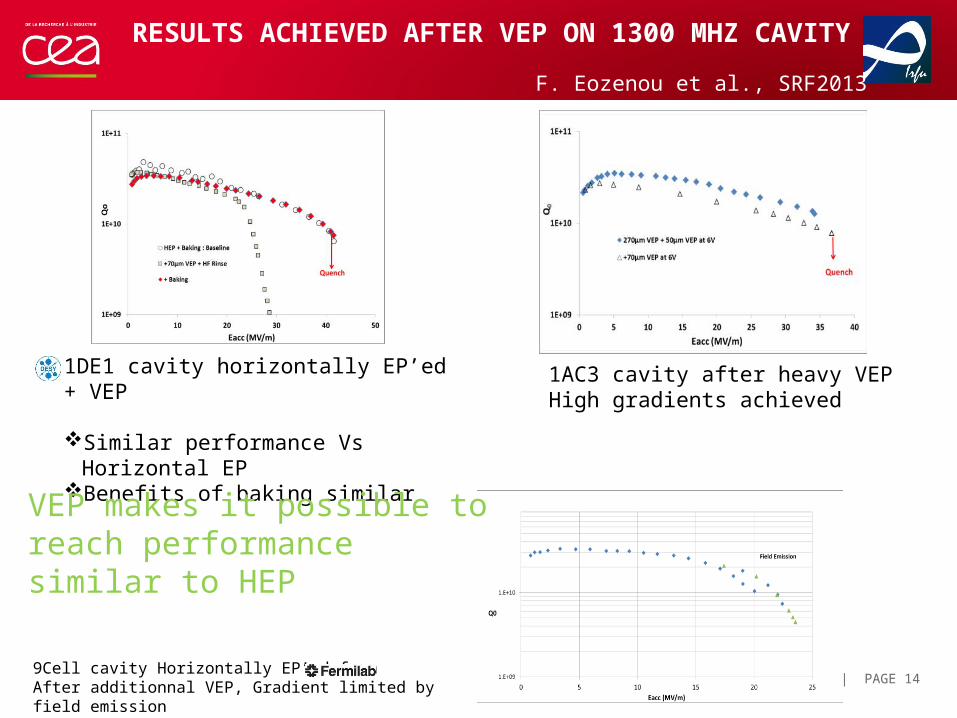
RESULTS ACHIEVED AFTER VEP ON 1300 MHZ CAVITY
| PAGE 149Cell cavity Horizontally EP’ed fromAfter additionnal VEP, Gradient limited by field emission
1DE1 cavity horizontally EP’ed + VEP
Similar performance Vs Horizontal EPBenefits of baking similar
1AC3 cavity after heavy VEPHigh gradients achieved
F. Eozenou et al., SRF2013
VEP makes it possible to reach performance similar to HEP
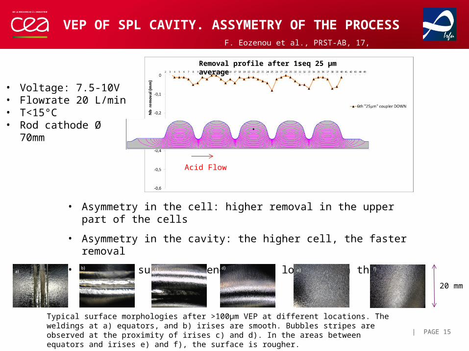
VEP OF SPL CAVITY. ASSYMETRY OF THE PROCESS
| PAGE 15
Acid Flow
Removal profile after 1seq 25 µm average
• Asymmetry in the cell: higher removal in the upper part of the cells
• Asymmetry in the cavity: the higher cell, the faster removal
• Achieved surface depends on the location in the cavity
Typical surface morphologies after >100µm VEP at different locations. The weldings at a) equators, and b) irises are smooth. Bubbles stripes are observed at the proximity of irises c) and d). In the areas between equators and irises e) and f), the surface is rougher.
20 mm
F. Eozenou et al., PRST-AB, 17, 083501 (2014) (2012)
• Voltage: 7.5-10V• Flowrate 20 L/min• T<15°C• Rod cathode Ø 70mm
| PAGE 16
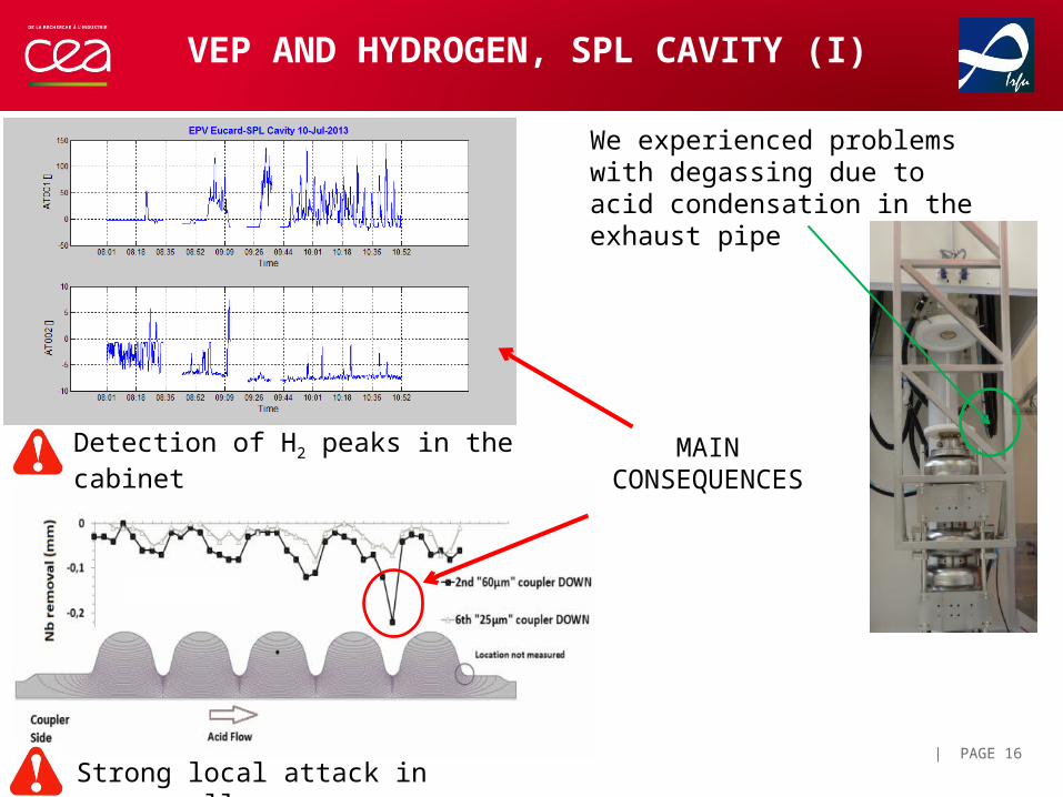
VEP AND HYDROGEN, SPL CAVITY (I)
Detection of H2 peaks in the cabinet
We experienced problems with degassing due to acid condensation in the exhaust pipe
Strong local attack in upper cells
MAIN CONSEQUENCES
| PAGE 17
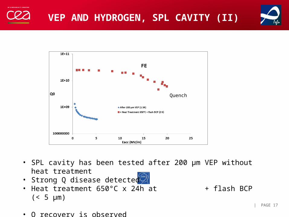
VEP AND HYDROGEN, SPL CAVITY (II)
• SPL cavity has been tested after 200 µm VEP without heat treatment• Strong Q disease detected• Heat treatment 650°C x 24h at + flash BCP (< 5 µm)
• Q recovery is observed
Quench
FE
FIELD FLATNESS EVOLUTION AFTER VEP
| PAGE 18
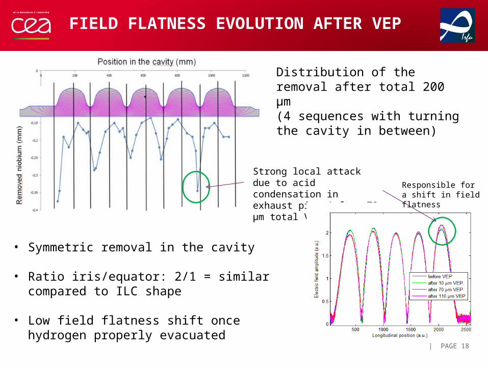
• Symmetric removal in the cavity
• Ratio iris/equator: 2/1 = similar compared to ILC shape
• Low field flatness shift once hydrogen properly evacuated
Strong local attack due to acid condensation in exhaust pipe (after 70 µm total VEP)
Distribution of the removal after total 200 µm (4 sequences with turning the cavity in between)
Responsible for a shift in field flatness
| PAGE 19
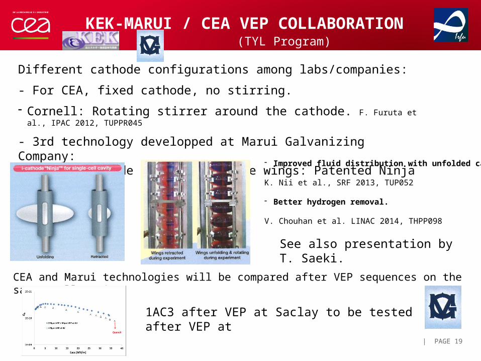
KEK-MARUI / CEA VEP COLLABORATION
Different cathode configurations among labs/companies:
- For CEA, fixed cathode, no stirring.
- Cornell: Rotating stirrer around the cathode. F. Furuta et al., IPAC 2012, TUPPR045
- 3rd technology developped at Marui Galvanizing Company:Rotating cathode with retractable wings: Patented Ninja Cathode
- Improved fluid distribution with unfolded cathode.
K. Nii et al., SRF 2013, TUP052
- Better hydrogen removal.
V. Chouhan et al. LINAC 2014, THPP098
See also presentation by T. Saeki.
CEA and Marui technologies will be compared after VEP sequences on the same 1Cell cavity
1AC3 after VEP at Saclay to be tested after VEP at
(TYL Program)
| PAGE 20
CONCLUSIONS
• VEP is a much simpler process, adapted to industrial scale
• A safer process
• Makes it possible to treat ‘big’ cavities and cavities with He tank
• CEA has developped VEP with low voltage and high acid flow
• Results after VEP / HEP are similar on Tesla shape cavities
• However it is an asymmetric process
• Surface less homogenous compared to HEP
• Using a rod cathode, cavity must be turned over for symmetric removal
Studies are on going for further improvement
THANK YOU FOR YOUR ATTENTION
| PAGE 21