- Metal Forming CAE Lab.msjoun.gnu.ac.kr/pub/2011-Papers/conference/JSTP_RP.pdf · tube forming...
20
Finite element analysis of a Mannesmann roll piercing process JSTP International session www.afdex.com AFDEX S. H. Sim1, J. M. Cho1, M. C. Lee2, M. S. Joun3 (speaker) S.H Sim J.M. Cho, M.C. Lee, M.S. Joun, Gyeongsang National Univ., Korea
-
Upload
dangkhuong -
Category
Documents
-
view
228 -
download
2
Transcript of - Metal Forming CAE Lab.msjoun.gnu.ac.kr/pub/2011-Papers/conference/JSTP_RP.pdf · tube forming...

Finite element analysis
of a Mannesmann roll piercing process
JSTP International session
www.afdex.com
AFDEX
S. H. Sim1, J. M. Cho1, M. C. Lee2, M. S. Joun3 (speaker)
S.H Sim J.M. Cho, M.C. Lee, M.S. Joun, Gyeongsang National Univ., Korea

Contents
▣ Introduction
▣ Conclusions
⊙ Research aim
⊙ Literature survey
▣ Finite element analysis
⊙ Research objects
⊙ Process conditions
⊙ Predictions
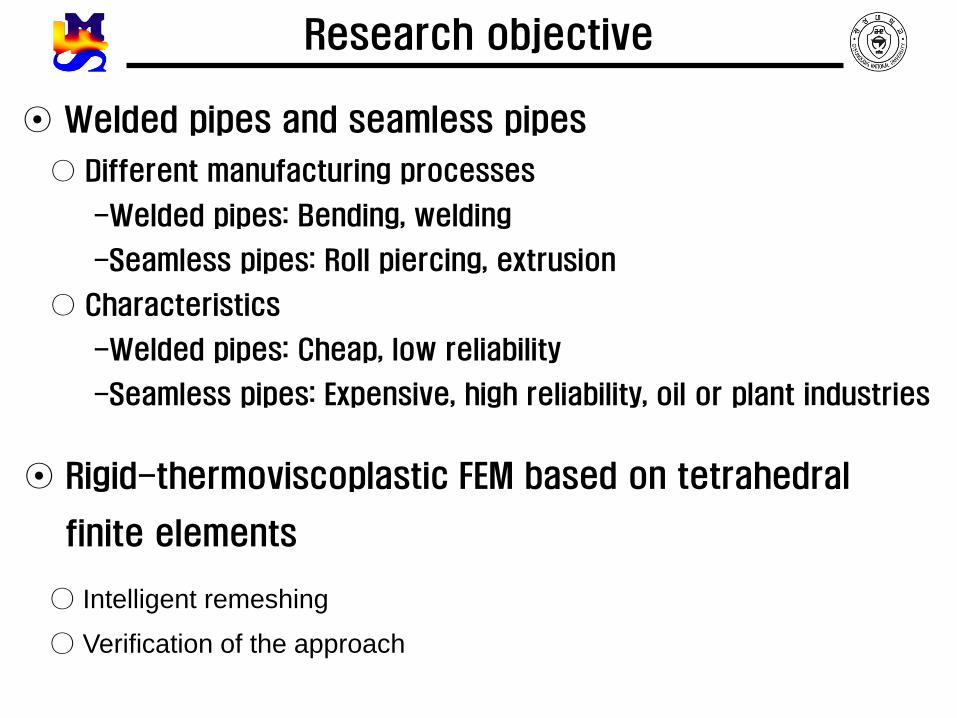
⊙ Welded pipes and seamless pipes
○ Different manufacturing processes
-Welded pipes: Bending, welding
-Seamless pipes: Roll piercing, extrusion
○ Characteristics
-Welded pipes: Cheap, low reliability
-Seamless pipes: Expensive, high reliability, oil or plant industries
Research objective
⊙ Rigid-thermoviscoplastic FEM based on tetrahedral
finite elements
○ Intelligent remeshing
○ Verification of the approach

1) Kazutake Komori, Kouta Mizuno, “Study on plastic deformation in cone-type rotary piercing
process using model piercing mill for modeling clay”, Journal of Materials Processing
Technology, 4994–5001, 2009
2) Ken-ichiro Mori, Hidenori Yoshimura, Kozo Osakada, Kazutake Komoria, Kouta Mizunob,
“Simplified three-dimensional simulation of rotary piercing of seamless pip by rigid- plastic
finite-element method”, Journal of Materials Processing Technology 80-81, 700-706, 1996
3) Kazutake Komori, “Simulation of Mannesmann piercing process by the three-dimensional
rigid-plastic finite-element method”, International Journal of Mechanical Sciences 47, 1838–
1853, 2005
4) B. Li, S.H. Zhang, G.L. Zhang, H.Q. Zhang, “Prediction of 3-D temperature field
of TP2 copper tubes in three-roll planetary rolling process”, journal of materials
processing technology 2 0 5 ( 2 0 0 8 ) 370–375
5) Z. Pater, J. Kazanecki, J. Bartnicki , “Three dimensional thermo-mechanical simulation of the
tube forming process in Diescher’s mill”, Journal of Materials Processing Technology, Vol.
177, pp.67–170, 2006
6) W. A. Khudheyer, D. C. Barton, T. Z. Blazynski, “A comparison between macroshear
redundancy and loading effects in 2- and 3-roll rotary tube cone piercers, Journal of
Materials Processing Technology, Vol. 65, pp. 191-202, 1997
Literature survey
7) Kazutake Komor, Minoru Suzuki, Simulation of deformation and temperature in
press roll piercing, Journal of Materials Processing Technology, Vol. 169, pp. 249–257, 2005
8) Sudhir Chiluveru, “Computational Modeling of Crack Initiation in Crossroll Piercing”
9) Dr.-Ing. Karl-Heinz Brensing, Düsseldorf Dipl.-Ing. Baldur Sommer, Salzgitter Großrohre
GmbH, “Steel Tube and Pipe Manufacturing Processes”
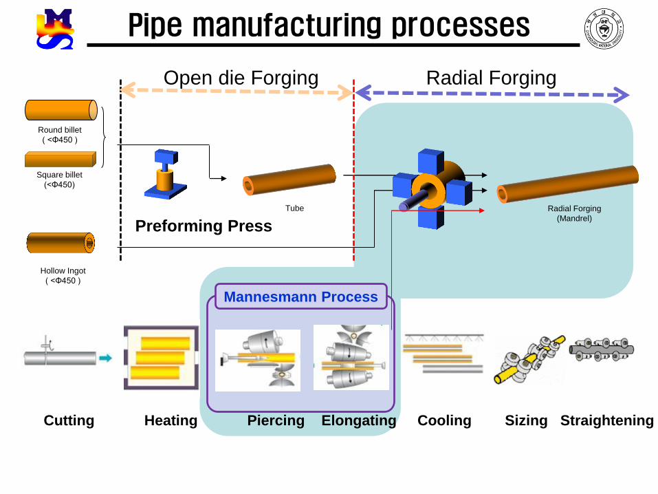
Square billet
(<Φ450)
Round billet
( <Φ450 )
Tube Radial Forging
(Mandrel)
Hollow Ingot
( <Φ450 )
Open die Forging Radial Forging
Preforming Press
Cutting Heating Piercing Elongating Cooling Sizing Straightening
Mannesmann Process
Pipe manufacturing processes

Concept of roll piercing process
⊙ Conceptual diagram of Mannesmann roll piercing ⊙ Roll piercing equpiment

Research objects
⊙ Diescher’s roll piercing process

Process design
Work roll
Mandrel Disk Pusher

Process and material conditions
⊙ Rolls and tools
Item velocity Law of friction Friction factor Initial temp.
Work roll 60 rpm Sticking - 100℃
Disk 6.8 rpm Constant shear friction 0.4 100℃
Mandrel - - 0.0 300℃
Pusher 20m/s - 0.0 0℃
Initial temp. Ambient temp. Heat transfer coef.
with dies
Heat transfer coef.
with environments
Thermal
conductivity
1180℃ 80℃ 10000 200 0.033
⊙ Material conditions
2W/m K 2W/m K 2W/m K

Flow stress of material
Strain rate(/s)
Tru
es
tre
ss
(MP
a)
0 10 20 30 40 500
50
100
150
200
250
300
900
1000
1100
1200
℃
0.01
0.10
0.70
0.30
0.50
⊙: SUJ(100Cr6)
True stress-strain rate curves
℃
℃
℃
℃
0.01 900 129.6900 0.1230
0.10 900 144.1000 0.1230
0.30 900 175.8200 0.1070
0.50 900 178.5700 0.1070
0.70 900 160.6500 0.1310
0.01 1000 88.7360 0.1460
0.10 1000 98.5950 0.1460
0.30 1000 122.0400 0.1270
0.50 1000 122.0400 0.1290
0.70 1000 115.8300 0.1340
0.01 1100 58.9500 0.1690
0.10 1100 65.5000 0.1690
0.30 1100 82.7370 0.1430
0.50 1100 84.8060 0.1430
0.70 1100 82.7370 0.1480
0.01 1200 41.5750 0.2030
0.10 1200 46.1950 0.2030
0.30 1200 57.2260 0.1710
0.50 1200 57.2260 0.1780
0.70 1200 53.0900 0.1920
C n

Predictions
⊙ After 1.0 second
200 mm

Predictions
⊙ After 2.0 seconds
210 mm

Predictions
⊙ After 3.0 seconds
228 mm

Predictions
⊙ After 4.0 seconds
262 mm

Comparison with Pater et al.
1 3 5
2 4 6
1 3 5
2 4 6

Comparison with Pater et al.
1 2 3 4 5 6
Ellipticity 1.038 1.0295 1.045 1.054 1.004 1.0279
1 3 5
2 4 6
1 3 5
2 4 6
1 2 3 4 5 6
Ellipticity 1.032 1.031 1.044 1.056 1.000 1.007
Difference(%) 0.57 0.15 0.10 0.19 0.40 2.03

Comparison of temperature

Change of volume during simulation
Stroke(s)
Vo
lum
eC
ha
ng
e(%
)
0 1.25 2.5 3.75 5-0.1
-0.05
0
0.05
0.1
⊙ Volume vs. Stroke

Predictions – animation

⊙ Mannesmann roll piercing with Diescher’s type guiding disk was
simulated by AFDEX 3D
-Rigid-Thermoviscoplastic FEM
-Intelligent remeshing with tetrahedral elements
⊙ Comparison with Pater et al.
-Good agreement in term of deformed shape
-Much more reliable predictions
Conclusions