· LANL Engineering Standards Manual STD-342-100 Chapter 7, Electrical Section D5090 – Other...
43
LANL Engineering Standards Manual STD-342-100 Chapter 7, Electrical Section D5090 – Other Electrical Systems Rev. 4, 11/8/11 Page 1 of 43 TABLE OF CONTENTS D5090 OTHER ELECTRICAL SYSTEMS 1.0 GENERAL ...............................................................................................................................4 1.1 Applicable Sections ................................................................................................................................ 4 1.2 System Survivability .............................................................................................................................. 4 2.0 ENGINE-GENERATOR SYSTEMS ............................................................................................5 2.1 General ................................................................................................................................................... 5 2.2 Minimum Rating .................................................................................................................................... 6 2.3 Reliability/Maintainability ..................................................................................................................... 8 2.4 Energy Source ........................................................................................................................................ 9 2.5 Transfer Equipment .............................................................................................................................. 10 2.6 Starting System .................................................................................................................................... 11 2.7 Remote Annunciation ........................................................................................................................... 12 2.8 Noise and Vibration Control ................................................................................................................ 12 2.9 Load Testing Provisions ....................................................................................................................... 13 2.10 Generator Output .................................................................................................................................. 13 2.11 Grounding............................................................................................................................................. 13 2.12 Acceptance Testing .............................................................................................................................. 14 3.0 STORED EMERGENCY POWER SUPPLY SYSTEMS ...............................................................14 3.1 General ................................................................................................................................................. 14 3.2 SEPSS Selection ................................................................................................................................... 14 3.3 SEPSS Acceptance Testing and Inspection .......................................................................................... 15 4.0 UPS SYSTEMS ......................................................................................................................16 4.1 General ................................................................................................................................................. 16 4.2 UPS Selection ....................................................................................................................................... 16 4.3 UPS Configuration ............................................................................................................................... 20 4.4 UPS Installation.................................................................................................................................... 22 4.5 Building Auxiliary Systems ................................................................................................................. 23 4.6 UPS System Acceptance Testing and Inspection ................................................................................. 24 5.0 STATIONARY BATTERY POWER SYSTEMS ..........................................................................24 5.1 General ................................................................................................................................................. 24 5.2 Battery Power System Configuration ................................................................................................... 25 5.3 Installation ............................................................................................................................................ 28 5.4 Battery System Acceptance Testing and Inspection ............................................................................. 31 6.0 CABLE TRAY SYSTEMS........................................................................................................31 6.1 Cable Tray Selection ............................................................................................................................ 31 6.2 Cable Tray Installation ......................................................................................................................... 32 6.3 Cable Installation.................................................................................................................................. 33 7.0 SIGNAL REFERENCE GRID ..................................................................................................34 8.0 LIGHTNING PROTECTION SYSTEMS....................................................................................34 8.1 Criteria.................................................................................................................................................. 34 8.2 Grounding System ................................................................................................................................ 36 8.3 Installation ............................................................................................................................................ 37 8.4 Surge Protection ................................................................................................................................... 38 8.5 Acceptance Inspection .......................................................................................................................... 39 9.0 SOLAR PHOTOVOLTAIC (PV) SYSTEMS ..............................................................................39 9.1 Stand-Alone PV Systems ..................................................................................................................... 39
Transcript of · LANL Engineering Standards Manual STD-342-100 Chapter 7, Electrical Section D5090 – Other...

LANL Engineering Standards Manual STD-342-100 Chapter 7, Electrical Section D5090 – Other Electrical Systems Rev. 4, 11/8/11
Page 1 of 43
TABLE OF CONTENTS
D5090 OTHER ELECTRICAL SYSTEMS
1.0 GENERAL ...............................................................................................................................4 1.1 Applicable Sections ................................................................................................................................ 4 1.2 System Survivability .............................................................................................................................. 4
2.0 ENGINE-GENERATOR SYSTEMS ............................................................................................5 2.1 General ................................................................................................................................................... 5 2.2 Minimum Rating .................................................................................................................................... 6 2.3 Reliability/Maintainability ..................................................................................................................... 8 2.4 Energy Source ........................................................................................................................................ 9 2.5 Transfer Equipment .............................................................................................................................. 10 2.6 Starting System .................................................................................................................................... 11 2.7 Remote Annunciation ........................................................................................................................... 12 2.8 Noise and Vibration Control ................................................................................................................ 12 2.9 Load Testing Provisions ....................................................................................................................... 13 2.10 Generator Output .................................................................................................................................. 13 2.11 Grounding............................................................................................................................................. 13 2.12 Acceptance Testing .............................................................................................................................. 14
3.0 STORED EMERGENCY POWER SUPPLY SYSTEMS ...............................................................14 3.1 General ................................................................................................................................................. 14 3.2 SEPSS Selection ................................................................................................................................... 14 3.3 SEPSS Acceptance Testing and Inspection .......................................................................................... 15
4.0 UPS SYSTEMS ......................................................................................................................16 4.1 General ................................................................................................................................................. 16 4.2 UPS Selection ....................................................................................................................................... 16 4.3 UPS Configuration ............................................................................................................................... 20 4.4 UPS Installation .................................................................................................................................... 22 4.5 Building Auxiliary Systems ................................................................................................................. 23 4.6 UPS System Acceptance Testing and Inspection ................................................................................. 24
5.0 STATIONARY BATTERY POWER SYSTEMS ..........................................................................24 5.1 General ................................................................................................................................................. 24 5.2 Battery Power System Configuration ................................................................................................... 25 5.3 Installation ............................................................................................................................................ 28 5.4 Battery System Acceptance Testing and Inspection ............................................................................. 31
6.0 CABLE TRAY SYSTEMS ........................................................................................................31 6.1 Cable Tray Selection ............................................................................................................................ 31 6.2 Cable Tray Installation ......................................................................................................................... 32 6.3 Cable Installation .................................................................................................................................. 33
7.0 SIGNAL REFERENCE GRID ..................................................................................................34
8.0 LIGHTNING PROTECTION SYSTEMS ....................................................................................34 8.1 Criteria .................................................................................................................................................. 34 8.2 Grounding System ................................................................................................................................ 36 8.3 Installation ............................................................................................................................................ 37 8.4 Surge Protection ................................................................................................................................... 38 8.5 Acceptance Inspection .......................................................................................................................... 39
9.0 SOLAR PHOTOVOLTAIC (PV) SYSTEMS ..............................................................................39 9.1 Stand-Alone PV Systems ..................................................................................................................... 39
LANL Engineering Standards Manual STD-342-100 Chapter 7, Electrical Section D5090 – Other Electrical Systems Rev. 4, 11/8/11
Page 2 of 43
9.2 Interactive PV Systems ........................................................................................................................ 39 9.3 PV System Products ............................................................................................................................. 40 9.4 Installation Design ................................................................................................................................ 40
RECORD OF REVISIONS
Rev Date Description POC OIC
0 6/28/99 Rewritten and reformatted to support LIR 220-03-01. Superseded Facilities Engineering Standards, Volume 7, Electrical, Manual Rev 15, 6/26/98.
David W. Powell, PM-2
Dennis McLain, FWO-FE
1 11/18/02
General revision and addition of endnotes. Replaces Subsections: 212, 246.6, 261, 262, and 263.
David W. Powell, FWO-SEM
Kurt A. Beckman, FWO-SEM
2 10/27/06 Updated references to codes and standards; added requirement for NRTL listing of low-voltage engine-generator systems (EGS); added reliability and maintainability requirements for EGS; added alternative for air starting system for EGS 1000 kW and larger; added requirement to use #2 diesel fuel instead of biodiesel for Level 1 EGS; added EGS system survivability requirements; added correlation between EGS/UPS “Class” and NEC Articles 700, 701, and 702; added requirement for UPS selection based on load profile; added UPS system survivability requirements; added NFPA 70E as a design requirement for battery rooms and enclosures; added battery power system survivability requirements; added personnel lightning protection for open shelters. Organization and contract reference updates from LANS transition. ISD number changes based on new Conduct of Engineering IMP 341. Master Spec number/title updates. Other administrative changes.
David W. Powell, ENG-DECS
Kirk Christensen, CENG-OFF
3 3/18/11
Verified and updated referenced codes and standards; in most instances changed “safety class” to “safety class and safety significant;” added references to LMS Section 26 0548; consolidated “survivability” requirements for several systems into one article; clarified that EGS are for standby or emergency power systems; added requirement to indicate EGS and UPS type, class, and level on the one-line diagrams; revised Tables D5090-1 & 2 to better align with codes and DOE standards; expanded fuel storage system design and installation requirements and required coordination of design with ENV-RCRA; described use of switchgear electrically-operated circuit breakers as transfer equipment for large standby power systems; added requirement to
David W. Powell, ES-DE
Larry Goen, CENG-OFF

LANL Engineering Standards Manual STD-342-100 Chapter 7, Electrical Section D5090 – Other Electrical Systems Rev. 4, 11/8/11
Page 3 of 43
consider redundant starting system for EGS supporting emergency, safety class, or safety significant loads; added requirement that EGS be certified for compliance to seismic and wind criteria in the IBC and ASCE 7; added new article to address stored energy emergency power systems (SEPSS); clarified that UPS systems 12 kVA and over must have a full-capacity rated, continuous -duty static bypass switch; provided guidance on acceptable provisions for performing UPS and battery acceptance and maintenance capacity tests; added requirement that UPS using VRLA battery have means to detect and control thermal runaway; changed threshold of applicability of Stationary Battery Systems article from 115 Vdc to 50 Vdc to align with changes in NFPA 70E; added NFPA 1 requirements for storage batteries; added table with guidance for preventing, detecting, and controlling VRLA battery thermal runaway; revised battery room requirements to align with NFPA 1; incorporated LMS Section 26 0536 by reference; deleted cable tray installation requirements addressed by LMS Section 26 0536; added requirement to perform and document lightning risk assessments; raised threshold for lightning protection from $1M to $3M for building contents; updated SPD classifications to match current NFPA 780; revised requirements for explosives facilities to align with new Chapter 8 in NFPA 780.
4 11/8/11 Surge protection requirements per ANSI/UL, 3rd Edition and NEC Article 285; added requirements for solar photovoltaic systems.
David W. Powell, ES-DE
Larry Goen, CENG-OFF

LANL Engineering Standards Manual STD-342-100 Chapter 7, Electrical Section D5090 – Other Electrical Systems Rev. 4, 11/8/11
Page 4 of 43
D5090 OTHER ELECTRICAL SYSTEMS
1.0 GENERAL
1.1 Applicable Sections A. Requirements and guidance in LANL Engineering Standards Manual (ESM) Chapter 1
Sections Z10 and 200-230, and Chapter 7 Section D5000 also apply to this Section.
1.2 System Survivability A. The system survivability requirements described in the paragraphs below apply to the
following systems:
1. Engine-generator systems (EGS), 2. Stored energy emergency power supply systems (SEPSS), 3. Uninterruptible power supply (UPS) systems, and 4. Stationary battery systems.
B. Do not locate components or auxiliary equipment (e.g., conductors, disconnecting means, overcurrent protective devices, transfer equipment, fuel day tanks, and all control, supervisory, and support devices up to and including the branch circuit panelboards) for the systems listed in paragraph A in a location that is subject to flooding.1
1. Water from fire fighting,
Consider the following as potential flooding events:
2. Sewer backups, 3. Pipe breaks that require more than 2 hours to shut down, and 4. Water from a 100-year natural phenomena event.
C. Separate components and auxiliary equipment for the systems listed in paragraph A from normal power service and/or system equipment as follows2
1. Level 1 system components and equipment shall not be installed in the same room with the normal electrical service equipment or with normal power system distribution equipment rated over 150 volts to ground 1000 amperes or more. Refer to Section D5010 paragraph 2.2 for definition of service point.
:
2. Level 2 system components and equipment shall not be installed in the same room with the normal service equipment rated over 150 volts to ground and equal to or greater than 1000 amperes.
D. Design supports, anchorage, and bracing for components and auxiliary equipment for the systems listed in paragraph A in accordance with seismic and, if applicable, wind design requirements in ESM Chapter 5 and the more stringent requirements of NFPA 110 or 111, the IBC, and ASCE 7 Chapter 13. Refer to LANL Master Specification Section 26 0548, Vibration and Seismic Controls for Electrical Systems for material and installation requirements.
1 NFPA 110 §7.2.3 and NFPA 111 §7.2.2 2 NFPA 110 §7.2.2 and Annex A §A7.2.2. The NFPA 110 logic for protecting generator-based emergency and standby power
equipment from damage is extended to stored energy based emergency and standby power equipment. Just as for generator-based systems, appropriate consideration must be given to providing adequate fire and arc-blast protection to SEPSS, UPS, and stationary battery equipment so a single event will not disable both the normal and the emergency or standby power systems.

LANL Engineering Standards Manual STD-342-100 Chapter 7, Electrical Section D5090 – Other Electrical Systems Rev. 4, 11/8/11
Page 5 of 43
E. The following special systems have an Ip of 1.5 and must be capable of performing their intended function during and after a design basis seismic event:
1. Level 1 engine-generator systems (EGS).3
2. Stored energy emergency power supply systems (SEPSS).
Such systems support life safety systems (e.g. emergency lighting, fire pumps), safety class systems, and safety significant systems.
4
3. Level 1 uninterruptible power supply (UPS) systems. Such systems support life safety emergency lighting and power systems, safety class systems, and safety significant systems.
Such systems support emergency lighting systems.
4. Stationary battery power systems. Such systems support safety class systems, safety significant systems, life safety systems, utility switchgear control systems, and critical (e.g. 911) central office telecommunications systems. The batteries themselves contain hazardous materials.
F. Active equipment for the above special systems must be certified by the manufacturer to be operable after a design seismic event in accordance with ESM Chapter 5 and Chapter 13 of ASCE 7. Additional IEEE equipment qualification standards described in Section D5000 (para. 12.0) are applicable to special systems designated safety class or safety significant.
2.0 ENGINE-GENERATOR SYSTEMS
2.1 General A. Design (including addressing furnishing, installation, and acceptance testing) of engine-
generator systems (EGS) for standby or emergency power systems using the latest editions of the following codes, standards and this Section:
1. EGSA 101P, Performance Standard for Engine Driven Generator Sets5
2. EGSA 100B, Performance Standard for Engine Cranking Batteries Used with Engine Generator Sets
3. EGSA 100C, Performance Standard for Battery Chargers for Engine Starting Batteries and Control Batteries (Constant Potential Static Type)
4. EGSA 100M, Performance Standard for Multiple Engine Generator Set Control Systems 5. EGSA 107T, Performance Standard for Generator Test Methods 6. ESGA 200W, Recommended Practice for Seismic and Wind Certification for Compliance
to the International Building Code (IBC) for Electrical Generating Systems and Various Critical Components for Building Design Categories C, D, E or F per Chapter 13 of ASCE 7 and Chapters 16 and 17 of the IBC Code
7. IEEE Std 446, IEEE Recommended Practice for Emergency and Standby Power Systems for Industrial and Commercial Applications
8. International Fire Code (e.g., Section 604) 9. NFPA 30, Flammable and Combustible Liquids Code 10. NFPA 37, Standard for the Installation and Use of Stationary Combustion Engines and
Gas Turbines 11. NFPA 54, National Fuel Gas Code
3 NFPA 110 §7.11.5 and §7.11.6; LANL is ASCE 7 seismic category D. 4 NFPA 111 §7.4.5; LANL is ASCE 7 seismic category D. 5 The Electrical Generating Systems Association (EGSA) is a trade association made up of nearly 600 companies in the USA
and around the world that make, sell, distribute, specify, service, and use on-site power equipment. The organization develops performance standards for on-site power technology.

LANL Engineering Standards Manual STD-342-100 Chapter 7, Electrical Section D5090 – Other Electrical Systems Rev. 4, 11/8/11
Page 6 of 43
12. NFPA 70, National Electrical Code (NEC) 13. NFPA 110, Standard for Emergency and Standby Power Systems 14. NMAC 20.5.4 (New Mexico Administrative Code Title 20 - Environmental Protection,
Chapter 5-Petroleum Storage Tanks, Part 4 - New and Upgraded Storage Tank Systems: Design, Construction and Installation)
15. STI F921, Standard for Aboveground Tanks with Integral Secondary Containment 16. STI R912, Installation Instructions for Shop Fabricated Aboveground Storage Tanks for
Flammable, Combustible Liquids 17. STI SP 001, Standard for the Inspection of Aboveground Storage Tanks 18. UL 142, Standard for Steel Aboveground Tanks for Flammable and Combustible Liquids 19. UL 2085 Standard for Protected Aboveground Tanks for Flammable and Combustible
Liquids 20. UL 2200, Standard for Stationary Engine Generator Assemblies (low-voltage EGS) 21. UL 2245, Below-Grade Vaults for Flammable Liquid Storage Tanks 22. 40 CFR 60, Standards of Performances for New Stationary Sources
B. Refer to Section D5000 (paragraph 12.0) for additional requirements applicable to EGS classified as ML-1, ML-2, safety class, or safety significant.
C. Refer to LANL Master Specification Section 26 3213 Engine Generators, once issued, for material and installation requirements.
2.2 Minimum Rating A. Design EGS that is capable of supplying all of the connected loads simultaneously, starting
connected motor loads, and providing not less than 20 percent future load growth at an altitude of 7500 feet and an ambient temperature of 100 F.6
B. EGS rated 600 volts or less shall be NRTL listed to UL 2200.
C. Select EGS so the two-cycle voltage dip will not exceed 25 percent7
D. If EGS is used to back-up UPS loads exceeding 25 percent of the EGS nameplate rating it must include an isochronous governor and an UPS compatible voltage regulator. EGS must be capable of simultaneously supporting the UPS load, UPS battery charging, and UPS room cooling
during the worst-case motor-starting scenario.
8
E. If EGS will be alternate supply to adjustable speed drive or similar harmonic-generating loads exceeding 25 percent of the EGS nameplate rating, assure that the non-linear loads can operate successfully when powered by the EGS
. Coordinate EGS selection with UPS and EGS manufacturers.
9
1. Provide EGS with an isochronous governor and voltage regulator suitable for high-harmonic loads.
. Coordinate with EGS and drive manufacturers to select cost-effective solution. Possible solutions include:
2. Provide drives with input filters to reduce current harmonic distortion.
6 Based on daily extremes for White Rock: http://weather.lanl.gov/html/WRExtremes.html 7 Voltage dip is based on the 25% drop out voltage for NEMA AC control relays. 8 IEEE Std 1100, paragraph 8.3.4.1. 9 IEEE Std 446, paragraph 6.4.2.3. In addition to concerns about effects of harmonics on EGS performance, concerns also
exist about interactions between adjustable speed drives served by relatively high impedance sources such as EGS.

LANL Engineering Standards Manual STD-342-100 Chapter 7, Electrical Section D5090 – Other Electrical Systems Rev. 4, 11/8/11
Page 7 of 43
Table D5090-1: EGS Classifications
Load NFPA 110 Type
(seconds, maximum)
NFPA 110 Class (hours,
minimum)
NFPA 110
Level
NEC Article
Emergency System (emergency power system required by IBC, NFPA 101, or other code)
10* 9610 1 700
Safety Class System (designated in safety analysis)
60* 96 or as required by safety analysis
1 702 plus applicable sections from 708**
Safety Significant System (designated in safety analysis)
60* 96 or as required by safety analysis
1 702 plus applicable sections from 708**
Legally Required Standby System (standby power system required by IBC, NFPA 101, or other code)
60* 2411 2 701
Security System 60* 2412 2 702
Critical Computing or Communications System (telephone central office or node, some SVTRs)
60* 24 2 702
Other Systems 60 8 2 702
* Some systems may require shorter periods of unacceptable power at the utilization equipment. In those cases the NFPA Type is the maximum time the load is permitted to be without acceptable input power. Some loads may require uninterrupted power; refer to the UPS Systems heading in Section D5090.
** For safety class (SC) and safety significant (SS) systems, also design EGS and distribution system in
accordance with the applicable provisions of the following NEC sections, substituting “Safety Class Power Systems” or “Safety Significant Power Systems” for “Critical Operations Power Systems” (or COPS): 708.3; 708.4; 708.5; 708.6; 708.8; 708.10(A), (B), and (C); 708.11(B); 708.12; 708.14(8) for HVAC systems that support the EGS; 708.20; 708.22; 708.24; 708.30; 708.50; 708.52; 708.54.
F. If EGS will be alternate supply to elevators loads exceeding 25 percent of the EGS nameplate rating, assure that elevator controller has provisions to absorb regenerative power13
10 NFPA 110 §5.1.2; required 96 hours on-site fuel supply for Level I systems is due to the ASCE 7 seismic design category D
assigned to LANL. 11 The NEC establishes minimum 2 hours duration of standby capability for “legally-required standby systems.” The duration
requirement is increased to 24 hours due to the remoteness of LANL. 12 DOE M 470.4-2A, Physical Protection, does not establish duration of standby capability power for security systems. This
requirement is set at 24 hours due to the remoteness of LANL. Telecommunications systems are considered to be an integral part of “defense in depth” security systems and are important to public safety.
13 NEC Section 620.91
. Coordinate EGS selection with elevator and EGS manufacturers.

LANL Engineering Standards Manual STD-342-100 Chapter 7, Electrical Section D5090 – Other Electrical Systems Rev. 4, 11/8/11
Page 8 of 43
G. Design EGS of the NFPA 110 type14, class15, and level16
1. Design EGS and associated distribution system to meet the NEC Article
to meet the user’s operational needs for emergency or standby power and to meet the minimum requirements in Table D5090-1.
17
2. Indicate EGS type, class, and level on the one-line diagram
indicated in Table D5090-1.
18
H. Specify engines that will meet “new source performance standards” required by 40 CFR 60.
.
2.3 Reliability/Maintainability A. Locate Level 2 EGS with nameplate rating greater than 400 kW19 and all Level 1 EGS in a
dedicated generator room designed to protect the EGS and accessories from wind driven debris and other natural phenomena hazards in accordance with DOE-STD-1020.20
1. Provide space heating for reliable starting and adequate cooling while EGS is operating.
21
2. Provide adequate space, access pathways, and other provisions necessary for safe and efficient maintenance, repair, and replacement of the EGS.
22
3. Refer to Chapter 7 of NFPA 110 for additional requirements.
B. For Level 1 EGS with required capacity at 7500 ft. greater than or equal to 1000 kW23, use an N+1 redundant parallel configuration of engine-generators, where N is the number of engine-generators required to serve the load.24
1. Determine the required number of engine-generator sets using procedures described in UFC 3-540-04N (MIL-HDBK-1003/11), Diesel-Electric Generating Plants.
2. An N+1 configuration will allow for maintenance or repair of an engine-generator while the EGS system continues to support the critical load.
3. Provide each engine-generator with an isochronous load sharing type governor.25
4. Provide each engine-generator with a regulator equipped for paralleling and connected for compensation by either the droop or the differential (cross current) method.
26
14 Type is maximum time (in seconds) that the load is permitted to be without acceptable power. Refer to NFPA 110 §4.3 and
Table 4.1(b). 15 Class is the minimum hrs of operation at full load without being refueled; see NFPA 110 §4.2 and Table 4.1(a). 16 Level indicates the stringency of requirements for installation, performance, and maintenance. Level is assigned to the
various kinds of loads on a graded approach based on consequence of failure. Refer to NFPA 110 §4.4. 17 NEC Article 700 addresses “emergency systems.” NEC Article 701 addresses “legally required standby systems.” NEC
Article 702 addresses “optional standby systems.” 18 Having the EGS type, class, and level indicated on the one-line diagram is requested by the LANL Electrical AHJ to assist
in plan reviews and acceptance testing. 19 400 kW is about the upper limit for standard commercial sound-attenuating weather-protective housings for EGS. 20 Chapter 3 of DOE-STD-1020-2002 21 NFPA 110 §5.3 and §7.7 22 NFPA 110 §7.2.5 23 EGS cost per kW is at a minimum in the 300 kW to 600 kW range, then increases 2X for 1000 kW sets and 2.5X for 2000
kW sets. Factoring in the added costs for paralleling switchgear indicates favorable costs for parallel EGS starting at 1000 kW with the required capacity made up of 300 to 600 kW sets.
24 Refer to IEEE Std 446 §4.2.6 and EGSA 100M §6.1; benefits of parallel-redundant EGS include: Reliability — Reliability is inherently greater with multiple generator sets. A faulty unit can be serviced or repaired while others maintain power; Economy — Several smaller units may cost less than one larger unit. Smaller units are easier to ship and install at the job site. Smaller units may be run or shut down as a function of load demand to increase engine life and to maintain high fuel efficiency; Modular design — Modular commonality of equipment with a lower cost structure and ease of upgrade to add additional units; Ease of installation — The ability to lift, move, and place the smaller engine-generators with conventional forklift trucks instead of heavy cranes; Availability — Delivery within normal lead times, unlike competing large units that are frequently backlogged; Reduced maintenance costs — Serviceable by diesel technicians at lower hourly rates, unlike larger single engine units requiring more specialized and costly service; Less expensive parts — Replacement and maintenance parts less expensive and more commonly available than for larger single engine units.
25 EGSA 100M §6.2.1
LANL Engineering Standards Manual STD-342-100 Chapter 7, Electrical Section D5090 – Other Electrical Systems Rev. 4, 11/8/11
Page 9 of 43
5. Provide each engine-generator with a dedicated fuel supply system that includes pumps, piping, and day tank. A common bulk fuel storage system may be used to the extent permitted by NFPA 110.
6. Provide automatic random access paralleling controls that use electrically-operated low-voltage power circuit breaker switchgear and control power from a stationary battery system or UPS system.27
C. For Level 1 EGS with required capacity at 7500 ft. of less than 1000 kW, use an N+1 parallel redundant configuration as described above, or provide a location for and means to safely connect a temporary EGS whenever the permanent generator is out of service for major maintenance or repair.
28
1. The means to connect the temporary EGS must be such that:
• No hazardous voltage will be present in the permanent generator or its control or protective devices when the temporary EGS is operating, and no hazardous voltage will be present in the temporary EGS or its control or protective devices when the
permanent EGS is operating29
• There is overcurrent protection for conductors and the temporary EGS as required by the NEC
, and
30
2. The location for the temporary EGS must be: .
• Designated and marked for the purpose, • Accessible for placing a trailer-mounted or portable unit of suitable size, and • Protective against natural phenomena hazards (e.g. wind-driven debris).
D. Specify water jacket heater(s) for each EGS installation.31
E. Specify battery heater(s) for each outdoor installation and as recommended by EGS manufacturer for indoor installations.
2.4 Energy Source32
A. Base EGS energy source (fuel) type selection on the following requirements and guidance:
1. Level 1 system: No. 2 Diesel fuel.33, 34
2. Level 2 system: No. 2 Diesel fuel or natural gas.
B. Design fuel system with adequate capacity to meet the NFPA 110 Class requirements plus capacity for required acceptance testing, periodic exercising, and testing.
C. Design fuel systems to meet the following codes and standards as applicable:
1. NFPA 30 2. NFPA 37
26 EGSA 100M §6.2.2 27 EGSA 100M §6.2.6 28 NEC Section 700.4(B). This NEC requirement for emergency systems applies to Level 1 systems. 29 NEC Section 445.18 30 NEC Section 445.12 31 NFPA 110 §5.3.1 32 NFPA 110 §5.1 33 On-site fuel supply is required because the probability of interruption of off-site fuel supply is considered high due to
remoteness of LANL and the possibility of seismic activity. 34 Biodiesel B5, B20, or B100 blends should not be used with EGS because of the limited experience with biodiesel fuels in
EGS service and concerns about the stability of this material during the long-term fuel storage typical of EGS. Refer to Assessing Biodiesel in Standby Generators for the Olympic Peninsula, Final Report, Prepared for the Bonneville Power Administration, July 2004. This document indicates good success with biodiesel in transportation equipment, but results ranging from success to failure in standby generator systems.

LANL Engineering Standards Manual STD-342-100 Chapter 7, Electrical Section D5090 – Other Electrical Systems Rev. 4, 11/8/11
Page 10 of 43
3. NFPA 54 4. NMAC 20.5.4.
D. Use NRTL-listed tanks and suitable secondary containment for liquid fuel systems as follows:
1. Single-wall steel tanks installed in aboveground or underground pre-fabricated concrete containment vaults that facilitate visual inspection for tank leaks. Tanks must meet applicable requirements in UL 142. Pre-fabricated concrete fuel tank vaults shall be NRTL-listed to UL 2245.
2. Above-ground, double-wall, steel tanks with supplemental mechanical and fire protection and suitable leak detection systems. Tanks must meet applicable requirements in UL 142; supplemental mechanical and fire protection must meet applicable requirements in UL 2085.
3. Underground storage tanks should be avoided due to the complex and evolving environmental regulatory requirements.
4. Fuel storage tanks and piping systems must be installed, tested, and inspected by qualified persons and in accordance with the following codes and standards as applicable: • STI F921, • STI R912, and • STI SP 001.
5. Coordinate design and installation requirements with the LANL Water Quality and RCRA Group (ENV-RCRA).
E. Connect fuel transfer pumps to the first power system bus downstream of the EGS transfer equipment.35
2.5 Transfer Equipment
A. Use transfer equipment that is suitable for the application and is acceptable to the LANL Electrical AHJ to transfer loads from the normal power source to the EGS.36
B. Use transfer equipment with automatic operation for emergency, safety class, safety significant, legally required standby, security, and critical computing or communications systems.
37
C. If the EGS is a “separately-derived system” as defined by the NEC, use 4-pole transfer equipment for 3-phase, 4-wire systems with same the voltage as the building service.
Other standby systems may use either manual or automatic transfer equipment.
38
D. Automatic transfer switches must be NRTL listed for emergency use
39
1. Select and protect automatic transfer switches according to the short circuit and over-voltage considerations outlined in IEEE Std. 446.
in accordance with UL 1008 – Standard for Safety for Transfer Switch Equipment.
40
2. Automatic transfer switches on emergency, safety class, safety significant, and legally required standby system must be the bypass-isolation type.
41
35 NEC Sections 700.12(B)(2) and 701.12(B)(2) 36 NFPA 110 Chapter 6 and IEEE Std 446 paragraph 6.3 37 NEC Sections 700.5(A), 701.5(A), and 708.24(A) 38 EGS usually have a factory-made connection from the generator neutral to the frame of the machine. The purpose of the 4-
pole transfer switch is compliance with NEC section 250.24(A)(5) which prohibits load side grounding connections to the grounded (neutral) conductor.
39 NEC Sections 700.5(C), 701.5(C), and 708.24(C) 40 Chapter 6 in IEEE Std 446 41 A bypass-isolation transfer switch permits safe maintenance of the transfer switch while keeping critical systems in
operation: refer to §4.3.10 in IEEE Std 446-1995.
LANL Engineering Standards Manual STD-342-100 Chapter 7, Electrical Section D5090 – Other Electrical Systems Rev. 4, 11/8/11
Page 11 of 43
E. For standby systems (not emergency systems) rated 800 A and greater, switchgear electrically-operated power circuit breakers with suitable under-voltage, negative-sequence voltage, and frequency relaying may be used as transfer equipment.
F. In addition to the requirements of the NEC and NFPA 11042
1. Time delay on start of EGS: 1 second.
, specify the following for automatic transfer equipment:
43
2. Time delay on transfer to EGS: 0 to 5 seconds, initially set at 1 second.
44
3. Time delay on retransfer to normal source: 30 minutes.
45
4. Transfer equipment operations counter.
46
5. In-phase monitor for motor loads.
47
G. Transfer equipment and the EGS must meet NEC Article 705 requirements if installed to permit operation in parallel with the utility source.
2.6 Starting System A. For engine-generator sets smaller than 1000 kW specify starting battery system as required by
NFPA 110 and the following:
1. Lead-acid type battery,48
2. Automatic battery charger, with equalize charge timer, that meets EGSA 100C. which meets EGSA 100B.
B. For engine-generator sets with nameplate rating of 1000 kW and larger specify either starting battery system as described above or a dedicated compressed air starting as described below. Consult with engine-generator manufacturer to determine which alternative best meets the particular operational requirements of the system.
1. Design air starting system sized for not less than 3 cranking cycles per engine.49
2. Provide two starting-air compressor units, one unit with an electric-motor drive, and one unit with a dual electric-motor/diesel-engine drive with battery start for the engine drive. Power electric compressor motors from the EGS.
3. Manifold compressed air receivers in parallel, each with safety valves, isolating and flow check valves, and automatic condensate drain trap assemblies. For normal operating each engine shall have its own starting air tank so that unsuccessful start of a specific engine does not deplete the available compressed air. Under emergency conditions, the manifold shall allow for alternate supply from other tanks to the engines.
4. Receiver construction shall conform to American Society of Mechanical Engineers (ASME) SEC 8D, Pressure Vessels, for the system pressures involved.
5. Use components of the compressed air starting system for no other purpose than EGS starting.
C. For EGS supporting emergency, safety class, or safety significant loads consider a redundant starting system consisting of either:
1. Compressed air starting and battery starting as described above.
42 NFPA 110 Chapter 6 43 NFPA 110 A.6.2.5 44 NFPA 110 6.2.7 45 NFPA 110 A.6.2.8 46 NFPA 110 A.6.2.13 47 In-phase transfer systems permit motors to continue to run with little disturbance to the electrical system and processes
during re-transfer operation; refer to §4.3.8 in IEEE Std 446. 48 The hazardous waste issues with nickel-cadmium batteries preclude their use; refer to §5.3.2 in IEEE Std. 446. 49 UFC 3-540-04N (MIL-HDBK-1003/11)

LANL Engineering Standards Manual STD-342-100 Chapter 7, Electrical Section D5090 – Other Electrical Systems Rev. 4, 11/8/11
Page 12 of 43
2. Two full capacity starting batteries, two independent battery chargers, and a diode isolation system that will automatically select either battery to start the engine if the other battery has deteriorated or failed.50
2.7 Remote Annunciation
A. For Level 1 systems, design the NFPA 110 required remote common alarm of EGS malfunction51
1. At a location in the facility that is outside the generator room and is observable.
at the following locations: 52
2. A location that is continuously staffed; this may be in another building that has control over the system or at a central monitoring facility.
B. For Level 2 systems, design the NFPA 110 required remote common alarm of EGS malfunction at a location in the facility that is outside the generator room and observable by personnel.
2.8 Noise and Vibration Control A. Design suitable noise and vibration isolation systems for EGS installed inside or outside of
buildings. The location of the EGS and the uses facilities and spaces adjacent to the EGS will influence the type and degree of noise and vibration isolation required.
B. Use the following noise control systems as appropriate to limit EGS air-borne noise to a maximum of 70 dB(A) measured at ground level exterior locations 50 feet in any direction from the center of the generator set53
1. Critical type muffler(s) providing 25 to 35-dB attenuation in the 125 to 1000 Hz range.
:
2. Exhaust discharge pointed up. 3. Sound deflecting barrier in front of radiator discharge opening.54
4. Sound-attenuating louvers on air-intake opening(s) into generator room.
5. Intake silencer for turbo-charged engines; may be combined with air cleaner. 6. Sound attenuating housings and/or sound barriers for outdoor installations.55
C. Design suitable noise and vibration isolation systems to limit EGS noise in nearby occupied rooms, spaces, or facilities as follows:
1. Industrial occupancies: Less than 10 dB(A) increase above ambient noise level when the EGS is operating at full load.
2. Office or laboratory occupancies: Less than 5 dB(A) increase above ambient noise level when the EGS is operating at full load.
D. Consult with the EGS manufacturer, vibration isolation system manufacturers, or an acoustical engineer to determine suitable noise and vibration isolation systems.
E. Refer to LMS Section 26 0548 – Vibration and Seismic Controls for Electrical Systems for material and installation requirements.
50 Starting battery system failure is most frequent cause of emergency generator failures; see IEEE Std. 446 Ch. 4. 51 NFPA 110 §5.6.5.2(4) 52 NFPA 110 §5.6.6 53 Information on Levels of Environmental Noise Requisite to Protect Public Health and Welfare with an Adequate Margin of
Safety, March 1974, prepared by the U.S. EPA Office of Noise Abatement and Control. 54 The radiator fan is a significant source of EGS noise. 55 Generator sets may be enclosed in commercially available weather-protective sound attenuating housings that reduce noise
to less than 70 dBA measured 15 meters away.

LANL Engineering Standards Manual STD-342-100 Chapter 7, Electrical Section D5090 – Other Electrical Systems Rev. 4, 11/8/11
Page 13 of 43
2.9 Load Testing Provisions A. For a Level 1 or Level 2 EGS, specify means to monthly exercise the system under not less
than 30 percent of nameplate kW rating or greater percentage if recommended by the EGS manufacturer.56
B. Design a permanently installed
57
1. The steady-state kW of the facility load connected to the EGS is less than 30% of the EGS nameplate kW rating.
load bank for a Level 1 or Level 2 EGS under either of the following circumstances:
2. The user is reluctant to use the facility load for the NFPA 110 required monthly exercising of the EGS.
C. Design system to automatically replace the load bank with the emergency or standby loads in case of failure of the primary source during load testing.58
D. Large standby (not emergency) systems that are designed to operate in parallel with the utility system may use the utility system as the load for testing and monthly exercising. Comply with requirements of NEC Article 705
59
2.10 Generator Output
.
A. Design an accessible circuit breaker in the generator output circuit; locate circuit breaker either on the EGS or at a location in sight from the EGS and within 25 ft circuit distance from the generator output terminals.60
B. Circuit breaker shall be the NEC required disconnecting means for the generator.
61
C. Circuit breaker shall provide overcurrent protection for the generator and the output conductors.
62
D. Specify ground fault detection and alarm system if the generator circuit breaker rating exceeds 1000 amperes on 480Y/277V systems.
63
E. Design conductors from the generator terminals to the circuit breaker terminal with an ampacity not less than 115 percent of the generator nameplate rating.
64
F. Refer to Section D5000 for overcurrent protective device selective coordination requirements.
2.11 Grounding A. Bond the EGS frame to the main grounding electrode ground bar or to a main grounding
electrode ground bar extension using IEEE 837 compression lugs and grounding electrode
56 NFPA 110 §8.4.2 57 NFPA 110 §8.4; the EGS must be exercised at least monthly under not less than 30% nameplate kW load. If the facility load
connected to the EGS does not meet this requirement, or is not available for operational reasons, a supplemental load bank must be provided. It is not practical to use portable load banks for the monthly exercising of all the EGSs at LANL.
58 NFPA 110 §8.4.2.2 59 NEC Article 705 addresses electric power production sources operating in parallel with a primary source of electricity, such
as a utility source. 60 UL 2200, section 25.3. For large EGS with output rated more than 800 amperes it may be advantageous to locate the output
circuit breaker in a switchgear assembly instead of on the EGS. 61 NEC Section 445.18 62 NEC Section 445.12 63 NEC Sections 700.6(D) and 701.6(D) 64 NEC Section 445.13

LANL Engineering Standards Manual STD-342-100 Chapter 7, Electrical Section D5090 – Other Electrical Systems Rev. 4, 11/8/11
Page 14 of 43
conductor sized per NEC Table 250.66. Bond the grounded conductor to the generator frame using a main bonding jumper sized per same table.65
2.12 Acceptance Testing
A. Specify acceptance testing of EGS as required by the NEC, EGSA 107T, and NFPA 110.66
1. Provide advance notification of acceptance testing to the LANL Electrical AHJ.
67
2. Tests shall be performed by qualified personnel such as the EGS manufacturer’s factory-trained technicians or technicians that are certified in accordance with ANSI/NETA ETT-2000, Standard for Certification of Electrical Testing Technicians.
3. In addition to tests required by the NEC and NFPA 110, verify successful operation of EGS and associated equipment with connected facility loads, and successful starting and operation of all connected motor loads.
4. Require a detailed record of acceptance test results on a form suitable for the purpose. 5. Require that analysis and recommendations with the acceptance test report.
B. Specify LANL witnessed factory acceptance testing of EGS as follows:
1. A single unit EGS nameplate rated 1000 kW or more, 2. Any multiple unit EGS; factory testing of multiple unit EGS must also include the
paralleling switchgear. 3. Any safety class or safety significant EGS.
C. Provide copies of the acceptance test report and all certifications required by NFPA 110 to the LANL Electrical AHJ and to the Facility Manager.
3.0 STORED EMERGENCY POWER SUPPLY SYSTEMS
3.1 General A. This article addresses permanently installed stored energy emergency power systems
(SEPSS) used to power emergency lighting systems.
B. An SEPSS consists of a storage battery, an inverter, and a transfer switch which together are capable of supporting single-phase or three-phase emergency lighting system loads for not less than the time required by NFPA 101 and the NEC, typically 90 minutes.
3.2 SEPSS Selection A. Use one or more SEPSS to power emergency lighting and exit signs in buildings that do not
have a Level 1 emergency generator but have more than 3 kW of emergency luminaire and exit sign load68
65 Refer to IEEE Std. 446 Chapter 7 for a discussion of the pros and cons of grounding the neutral at the generator and using 4-
pole transfer switches. Problems associated with multiple transfer switches, ground fault protection of the emergency system, and potential hazardous conditions during certain maintenance operations are largely eliminated through grounding the neutral at the generator and using 4-pole transfer switches.
66 NFPA 110 §7.13 67 NFPA 110 §7.13.3 68 SEPSS will have a higher initial cost than individual unit equipment emergency lights and exit signs; however, this higher
cost will be recovered in the reduced maintenance cost for the centralized SEPSS compared to that for the dispersed unit emergency equipment.
.
LANL Engineering Standards Manual STD-342-100 Chapter 7, Electrical Section D5090 – Other Electrical Systems Rev. 4, 11/8/11
Page 15 of 43
B. Select SEPSS with a transfer time from utility to battery powered inverter output not exceeding the following:
1. 16.7 milliseconds (NFPA 111 Type O, U, A or B) for emergency lighting systems with HID luminaires69
2. 10 seconds (NFPA 111 Type 10) for emergency lighting systems without HID luminaires .
C. Design (including the furnishing, installation, and acceptance testing) of SEPSS to meet the latest edition of the following codes and standards and this Section:
1. IEEE Std 446, IEEE Recommended Practice for Emergency and Standby Power Systems for Industrial and Commercial Applications
2. International Fire Code (e.g., Section 608) 3. NFPA 70, National Electrical Code (NEC) 4. NFPA 101, Life Safety Code 5. NFPA 111, Stored Energy Emergency and Standby Power Systems 6. UL 924, Emergency Lighting and Power Equipment.
D. Specify SEPSS to have sealed lead-calcium batteries with a 20-year design life70
E. Specify SEPSS to have an external maintenance-bypass
, housed in a cabinet.
71
F. De-rate SEPSS capacity for operation in an ambient temperature of 77 deg. F at 7500-ft elevation; consult manufacturer.
that will connect the emergency lighting load to utility power and completely isolate the SEPSS from the AC power source.
G. Design or specify means to safely and conveniently perform SEPSS acceptance and maintenance capacity tests72
H. Refer to LANL Master Specification Section 26 3334, Stored Energy Power Supply System for material and installation requirements.
required by NFPA 111.
3.3 SEPSS Acceptance Testing and Inspection A. Specify complete acceptance testing and inspection of completed SEPSS in accordance with
NFPA 11173
1. Provide advance notification of acceptance testing to the LANL Electrical AHJ.
.
2. Tests shall be performed by qualified personnel such as the SEPSS manufacturer’s factory-trained technicians or technicians that are certified in accordance with ANSI/NETA ETT-2000, Standard for Certification of Electrical Testing Technicians.
3. Make a detailed record of acceptance test results on a form suitable for the purpose. 4. Provide analysis and recommendations with the acceptance test report.
B. Specify that copies of the acceptance test report and all certifications be delivered to the LANL Electrical AHJ and to the Facility Manager.
69 A transfer time not exceeding 16.7 ms (1 cycle) is required to prevent HID luminaires from extinguishing and then needing
several minutes to re-start. 70 Long-life lead-calcium batteries will reduce the life-cycle cost of the SEPSS. 71 An external bypass switch permits safe maintenance of the SEPSS while keeping emergency systems in operation: refer to
§4.3.10 in IEEE Std. 446. 72 NFPA 111 §7.6.2 and §8.4.3 73 NFPA 111 §7.6
LANL Engineering Standards Manual STD-342-100 Chapter 7, Electrical Section D5090 – Other Electrical Systems Rev. 4, 11/8/11
Page 16 of 43
4.0 UPS SYSTEMS
4.1 General This heading addresses permanently installed uninterruptible power supply (UPS) systems rated 1 kVA and larger. It is anticipated that guidance will be added later addressing rack-mounted UPS equipment and plug connected commodity UPS equipment.
4.2 UPS Selection A. Design (including the furnishing, installation, and acceptance testing) of UPS systems to
meet the user’s operational needs for uninterruptible, computer-grade power in conformance to the latest edition of the following codes and standards and this Section:
1. IEEE Std 446, IEEE Recommended Practice for Emergency and Standby Power Systems for Industrial and Commercial Applications
2. IEEE Std 493, IEEE Recommended Practice for Design of Reliable Industrial and Commercial Power Systems
3. IEEE Std 944, IEEE Recommended Practice for the Application and Testing of Uninterruptible Power Supplies for Power Generating Stations
4. IEEE Std 1100, IEEE Recommended Practice for Powering and Grounding Electronic Equipment
5. International Fire Code (e.g., Section 608) 6. NFPA 1, Fire Code 7. NFPA 70, National Electrical Code (NEC) 8. NFPA 111, Stored Energy Emergency and Standby Power Systems 9. IEC 62040, Uninterruptible Power Systems (UPS) 10. NEMA PE 1, Uninterruptible Power Systems – Specification and Performance
Verification 11. UL 1778, Uninterruptible Power Systems.
B. Refer to Section D5000 (paragraph 12.0) for additional requirements applicable to UPS systems classified as ML-1, ML-2, safety class, or safety significant.
C. Design on-line, double-conversion UPS systems74
74 A UPS system with true online double conversion provides complete isolation from problems originating from utility or
generator power. Other UPS topologies may have lower initial costs, they may not provide protection against all power problems including power system short circuits, frequency variations, harmonics, and common-mode noise. Refer to IEEE Std. 446 §5.5.3.1.
(defined as UPS that continuously derive output alternating current power from direct current or high frequency alternating current).

LANL Engineering Standards Manual STD-342-100 Chapter 7, Electrical Section D5090 – Other Electrical Systems Rev. 4, 11/8/11
Page 17 of 43
Figure D5090-1: Typical Static UPS System
Figure D5090-2: Typical Rotary UPS System
D. Select static (refer to Figure D5090-1) or rotary (refer to Figure D5090-2) power conversion
UPS equipment and UPS energy storage system (e.g. batteries, flywheel, etc.) type based on a 20-year life-cycle cost analysis. Consider the following factors as applicable:
1. Initial cost of UPS, energy storage system, and directly associated building floor space (e.g., UPS room, battery room) and support systems (e.g., UPS cooling, battery room ventilation, and special plumbing).
2. UPS energy costs including those of directly related building support systems. 3. Scheduled maintenance costs for UPS, energy storage system, and directly associated
building floor space and support systems. 4. Predicted repair and replacement costs for UPS components, energy storage system, and
directly associated building support systems.
Rectifier/Charger
StaticSwitch
Inverter
Main Input
Bypass Line
Output to CriticalLoad
UPS Module
Battery
Bypass
Maintenance Bypass
N.C. N.C.N.O.
Rectifier/Charger
Inverter
Main Input
Inverter Bypass
Output to CriticalLoad
UPS Module
Battery
Bypass System Bypass
N.O.
M G
N.O.
Rotary Filter
(Motor/Generator)

LANL Engineering Standards Manual STD-342-100 Chapter 7, Electrical Section D5090 – Other Electrical Systems Rev. 4, 11/8/11
Page 18 of 43
E. Refer to LANL Master Specification Section 26 3353, Static Uninterruptible Power Supply for material and installation requirements for UPS rated 15 kVA and greater.
F. De-rate UPS capacity for operation at 7500-ft elevation; verify with manufacturer.
G. Select UPS based on a load profile that considers the following factors:
1. Type of load - Data processing equipment, main frame chilled water pump, etc. 2. Size of load - kVA or kW rating, horsepower, voltage, and amperage of load. 3. Switching pattern – Un-switched; cycled daily; cycled hourly; operated by thermostat;
building management system control. 4. Transient characteristics -- Specify inrush current magnitude and duration (i.e., 15 times
steady state RMS current for ¼ cycle for electric discharge lighting); range of power factor variation (i.e., as low as 0.4 lagging for electric discharge lighting); voltage dip.
5. Steady-state characteristics -- specify range of power factor, particularly if outside the 0.8 lagging to 1.0 range. UPS de-rating is normally required for the unusual circumstance of loads at leading power factor. Consult vendors if in doubt. In some cases a demand factor might be applicable to the load.
6. Special factors -- Harmonic characteristics; factors that vary with temperature or age. The designer may vary the load profile format. Estimated or approximated load data may be used in the absence of exact information but should be so identified.
7. Include not less than 20 percent future load growth capacity.
H. Evaluate the UPS application to anticipate problems and to adjust the design accordingly. The problems associated with UPS/load interaction can be reduced by:
1. Large Transformer Applications:
• Use a transformer specifically designed for the transient specifications of the UPS.
• Use a UPS with characteristics that will not cause the transformer to saturate. 2. Motor Applications:
• Use a UPS capable of providing motor inrush without current limiting.
• Transfer the load bus to an alternate source to start the motor and retransfer to the UPS after the motor has started.
• Oversize the UPS so the motor load represents a small portion of the UPS capacity.
• Use a UPS with an inverter filter that is compatible with synchronous motors. 3. Other Nonlinear Loads:
• Use a UPS with a modified inverter filter.
• Oversize the UPS.
• Avoid connection of electric discharge lighting to the UPS. Use other emergency sources for this lighting.
I. Provide UPS systems of the NFPA 111 type, class, and level to meet the user’s operational needs for uninterruptible, computer-grade power and the minimum requirements in Table D5090-2.
1. Design UPS and associated distribution system to meet the NEC Article indicated in Table D5090-2.
LANL Engineering Standards Manual STD-342-100 Chapter 7, Electrical Section D5090 – Other Electrical Systems Rev. 4, 11/8/11
Page 19 of 43
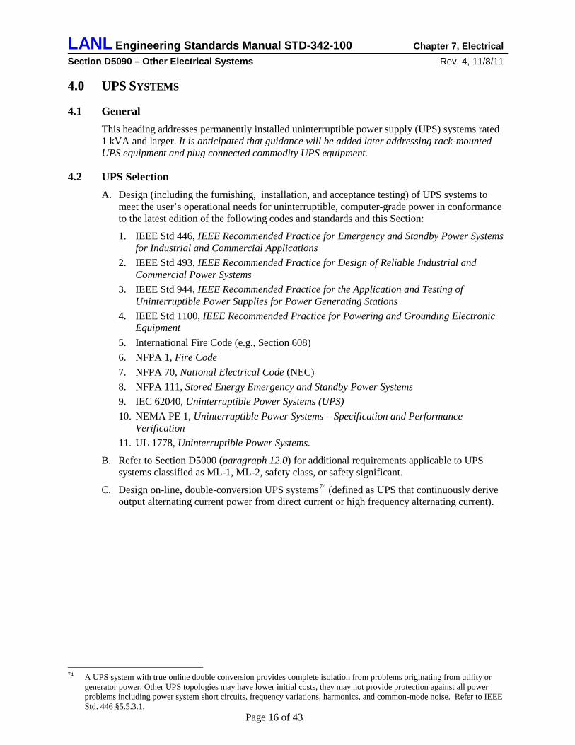
2. Indicate UPS type, class, and level on the one-line diagram75
Table D5090-2: UPS Classifications
.
All are NFPA 111 Type 076
Load
(0 seconds, max.)
NFPA 111 Class77 NFPA 111
Level
(hours, minimum)
78
NEC Article
Safety Class System (designated in safety analysis)
• 1.5 without generator backup (or as required by safety analysis)
• 0.25 with safety class EGS backup
1 702 plus applicable sections
from 708* Safety Significant System (designated in safety analysis)
• 1.5 without generator backup (or as required by safety analysis)
• 0.25 with safety class or safety significant EGS backup
1 702 plus applicable sections
from 708* Emergency System (emergency power system required by IBC or NFPA 101)
• 1.5 without generator backup • 0.25 with Level 1 EGS backup
1 700
Legally Required Standby System (standby power system required by IBC or NFPA 101)
• 1.5 without generator backup • 0.25 with Level 2 or Level 1 EGS backup
2 701
Critical Computing or Communications System (telephone central office or node, some SVTRs)
• 1.5 without generator backup • 0.25 with Level 2 or Level 1 EGS backup
2 702
Security System • 8 without generator backup79
• 0.25 with Level 2 or Level 1 EGS backup 2 702
Other Systems • 0.25 without generator backup (or longer to meet programmatic requirements)
• 0.083 with generator backup
2 702
* For safety class (SC) and safety significant (SS) systems, also design UPS and distribution system in accordance with the applicable provisions of the following NEC sections, substituting “Safety Class Power Systems” or “Safety Significant Power Systems” for “Critical Operations Power Systems” (or COPS): 708.3; 708.4; 708.5; 708.6; 708.8; 708.10(A), (B), and (C); 708.11(B); 708.12; 708.14(8); 708.20; 708.30; 708.50; 708.52; 708.54.
J. Select UPS manufacturers or vendors with emergency response capabilities80
1. Configuration of the UPS: single module or redundant configuration,
appropriate to meet the User’s requirement for availability of the UPS. Factors to consider in making such a selection include:
75 Having the UPS type, class, and level indicated on the one-line diagram is requested by the LANL Electrical AHJ to assist
in plan reviews and acceptance testing. 76 NFPA 111 §4.2.2. Type 0 characterizes UPS system with online double conversion. 77 NFPA 111 §4.3. Class is the minimum time, in hours, for which the UPS is designed to operate at rated load without being
recharged. Class is assigned to the various kinds of loads on a graded approach based on consequence of failure. NEC Sections 700.12(A) and 701.11(A) set the minimum run time at 1.5 hours for both emergency systems and legally required standby systems; NEC Section 700.12 indicates one or more type of system can be used to meet emergency or standby power requirements.
78 NFPA 111 §4.5. Level indicates the stringency of requirements for installation, performance, and maintenance. Level is assigned to the various kinds of loads on a graded approach based on consequence of failure.
79 DOE M 5632.1C-1 requires not less than 8 hours of standby capability power for security systems. 80 Emergency response time is the total time it takes for a service provider to arrive on the job site after an emergency service
request has been placed. Response time is based on Level using a graded approach based on consequence of failure.
LANL Engineering Standards Manual STD-342-100 Chapter 7, Electrical Section D5090 – Other Electrical Systems Rev. 4, 11/8/11
Page 20 of 43
2. Availability of qualified local service personnel to quickly diagnose UPS issues and make simple repairs,
3. Availability of an adequate local stock of spare parts for the UPS, and 4. Cost of a maintenance contract with the UPS manufacturer or vendor that includes a
specified on-call emergency response time.
4.3 UPS Configuration Select UPS system configuration using the following factors:
A. Specify bypass switches81
1. Provide UPS systems over 3.5 kVA with an automatic high-speed bypass switch.
based on the following requirements; refer to Figure D5090-1: 82
2. Provide three-phase UPS systems 12 kVA and over with a full-capacity rated, continuous duty static bypass switch.
82 3. Provide an external, manually operated, make-before-break maintenance bypass switch
with padlocking provisions or plug control for UPS systems 2 kVA and over.82 UPS module cabinet must be completely isolated and de-energized during maintenance.83
4. Install a separate bypass input circuit for three-phase UPS systems 12 kVA and over. 84
B. Certain critical loads such as safety class systems, safety significant systems, or critical telecommunications loads may require increased system reliability beyond that which can be provided by a single-module UPS system. Determine reliability requirements and system capabilities using analysis methods described in IEEE Std. 493.
85
1. Use two or more UPS modules, each with a dedicated energy storage system
Consider the following special configurations to increase UPS system reliability:
86, in isolated redundant configuration for systems with “single-cord” or “single-input” loads (typical equipment with a single power supply).87
2. Use two independent UPS systems, each with a dedicated energy storage system Refer to Figure D5090-3.
86, serving a dual-bus distribution system for systems with predominantly “dual-cord” loads (special “fault tolerant” computer and telecommunications equipment with dual full-capacity internal power supplies feeding a common internal power bus).88
3. Use an N+1 or an N+2 redundant parallel configuration of UPS modules, each with a dedicated energy storage system, where N is the number of UPS modules required to serve the load. This configuration allows for maintenance or repair of a UPS module while the UPS system continues to support the critical load.
81 Addition of a bypass switch makes the UPS system 8-10 times more reliable per IEEE Std. 446 §5.5.4.3. 82 Based on capabilities of commercially available products 83 An external bypass switch and external battery disconnect switch permits safe maintenance of the UPS while keeping
critical systems in operation: refer to §4.3.10 in IEEE Std. 446. 84 A separate bypass input source increases UPS system reliability and makes it possible to maintain the UPS and upstream
circuit breakers while still providing power to critical loads. 85 IEEE Std 493 Chapter 6 86 IEC 62040-3 defines a UPS unit (or module) as a complete UPS consisting of at least one each of the following functional
units: UPS inverter, UPS rectifier, and battery or other energy storage means which may operate with other UPS units to form a parallel or redundant UPS.
87 If the primary UPS module should fail, the secondary UPS module will continue to provide conditioned power to the critical load through the static switch in the Primary UPS module. The circuit breakers in the bypass switchgear can be arranged so either UPS module can support the critical load while maintenance or repairs are being performed on the other. See IEEE Std. 1100 §7.3.2.1.2.
88 Either UPS system can support the critical load while maintenance or repairs are being performed on the other.

LANL Engineering Standards Manual STD-342-100 Chapter 7, Electrical Section D5090 – Other Electrical Systems Rev. 4, 11/8/11
Page 21 of 43
Figure D5090-3: Typical Isolated-Redundant UPS System
C. Design grounding schemes for UPS systems in accordance with recommendations in IEEE
Std. 1100 Chapter 8.
D. Design or specify means to safely and conveniently perform UPS and battery acceptance and maintenance capacity tests89
1. Design circuit breakers, wiring, and heavy duty receptacle to connect an external adjustable load bank to the output of the UPS inverter. The critical load would be supplied through the external maintenance-bypass circuit.
while still providing power to the critical load bus. Acceptable methods to accomplish this include:
2. Specify UPS controls that use the UPS rectifiers and inverters as an internal load bank. UPS inverter output is connected to the UPS rectifier input through the static switch. UPS controls adjust the inverter output phase angle or voltage to cause up to full rated load current to flow. The critical load would be supplied through the external maintenance-bypass circuit.
89 NFPA 111 §7.6.2 and §8.4.3
Rectifier/Charger
StaticSwitch
Inverter
Source "B"
Bypass Line
Reserve UPS Module
Battery
Battery
Primary UPS Module
InverterRectifier/Charger
Bypass Line
StaticSwitch
Bypass Input
Main Input
Source "A"
Bypass Input
Main Input
N.O.
N.C.
N.C.
N.C.
N.O.
Output to CriticalLoad
BypassSwitchgear

LANL Engineering Standards Manual STD-342-100 Chapter 7, Electrical Section D5090 – Other Electrical Systems Rev. 4, 11/8/11
Page 22 of 43
E. If UPS energy storage system (i.e. batteries or flywheel) are in a separate cabinet or rack specify an external DC fused switch with padlocking provisions so the UPS cabinet can be completely isolated and de-energized. Refer to Figures D5090-1, -2, and -3.
F. Configure UPS battery in accordance with the Stationary Battery Power Systems heading of this chapter.
G. Where valve-regulated lead-acid (VRLA), lithium-ion, or lithium-polymer batteries will be the UPS energy storage, specify the UPS to have an NRTL-listed device or other approved method to preclude, detect, and control battery thermal runaway.90
H. Specify UPS battery monitoring systems
91
1. Each UPS module shall indicate UPS run time in minutes remaining and provide an alarm output contact at 5 minutes (field adjustable) remaining. Run time indication should be based on actual UPS load and battery discharge characteristic, not just a timer.
based on the following:
2. Use an NRTL-listed battery integrity monitoring system92
• UPS systems over 225 kVA
that operates on a battery interconnection point basis to monitor individual cells for the following systems:
• UPS systems with battery replacement cost over $20,000, and • UPS systems serving safety class or safety significant systems.
I. For UPS installed in information technology equipment rooms as defined in NEC Article 645, design remote EPO interface to shut down UPS AC output and to trip remote DC circuit breaker.93
J. Specify remote communications interface for UPS. UPS shall be Simple Network Management Protocol (SNMP) compatible and multi-computer interfaceable.
K. Three-phase UPS input current THD shall not exceed 10 percent.94
4.4 UPS Installation
NOTE: Be cautious about excessive harmonic currents when installing multiple single-phase UPS systems in a facility!
A. Locate UPS considering security, fire separation, noise, floor loading, heat rejection, installation and replacement access, maintenance access, spare parts storage, and the following guidance:95
1. UPS system 225 kVA and larger should be in a dedicated UPS room.
2. UPS louder than 60 dBA (measured one meter from the UPS) should not be located in any occupied space.
90 NFPA 1, §52.3.2 91 Since the battery is the most failure-prone sub-system of the UPS, monitoring battery condition is essential to UPS system
reliability. 92 Battery monitoring improves system reliability by detecting battery problems at an early stage, before they can cause an
abrupt system failure. Problems are detected by measuring the internal resistance of each cell or module in the system. The internal resistance of a cell is a reliable indicator of a battery’s state of health. The only other method for testing a battery’s condition is to perform a capacity test, but users are often reluctant to capacity tests their battery systems. With a suitable battery monitoring system a resistance test can be performed automatically by remote control. Refer to IEEE 1491 Guide for Selection and Use of Battery Monitoring Equipment in Stationary Applications.
93 NEC § 645.11 94 IEEE Std. 519, IEEE Recommended Practices and Requirements for Harmonic Control in Electrical Power Systems,
Chapter 10. Current total harmonic distortion (THD) at the service point is limited to 5%. It is anticipated that approximately half of the loads in a facility will be harmonic producing. Therefore significant individual harmonic producing loads, such as UPS, are limited to 10% current THD.
95 NFPA 111 Chapter 7
LANL Engineering Standards Manual STD-342-100 Chapter 7, Electrical Section D5090 – Other Electrical Systems Rev. 4, 11/8/11
Page 23 of 43
3. UPS serving safety class or safety significant systems should be installed in a dedicated UPS room rated for design basis accident.
B. Locate UPS battery considering floor loading, installation and replacement access, maintenance access, and the following guidance:96
1. Batteries should be physically isolated from UPS electronics to prevent corrosion of the electronics.
2. For a UPS system over 15 kVA, provide a separate battery compartment or cabinet with batteries on slide-out trays.
3. For a UPS system over 100 kVA, battery should be rack mounted in dedicated battery room; refer to the Stationary Battery Power Systems heading in this Section for installation requirements.
4. Battery for a three phase UPS system serving safety class or safety significant loads should be rack mounted in a dedicated battery room rated for design basis accident; refer to the Stationary Battery Power Systems heading in this Section.
4.5 Building Auxiliary Systems A. Design building auxiliary systems required for proper operation of the UPS system.
B. Design UPS room HVAC system considering operating temperature, continued operation, maintenance, and the following requirements:
1. Maintain a yearly average temperature of 77F with a 50F to 100F maximum range.97
2. Provide 30 percent efficiency air filtration.
98
3. UPS room HVAC must continue while UPS operates on battery power to keep the ambient temperature below 100F
99
4. UPS room cooling must continue during HVAC system maintenance
. If the UPS is supported by a generator, the UPS room cooling can be powered by the generator.
100
C. Require Class C portable fire extinguisher(s) at the UPS system. Consult with the LANL Fire Protection group to determine fire extinguisher size, type, and placement.
-- this often necessitates a redundant HVAC system for the UPS room.
D. Back-up EGS, if used, must be selected for UPS support including an isochronous governor and a UPS compatible voltage regulator.101
E. Design emergency lighting for the UPS and battery location.
Generator must be capable of simultaneously supporting the UPS load, UPS battery charging, and UPS room cooling. Coordinate selection with UPS manufacturer.
102
F. Specify UL 1449 Type 1 surge suppression device on each UPS input and bypass circuit buss.
Use both battery-powered emergency lights and fluorescent luminaires connected to a UPS supplied circuit.
103
96 For vented lead-acid batteries, see Chapter 5 in IEEE Std. 484. For valve-regulated lead-acid batteries, see Chapter 5 in
IEEE Std. 1187. 97 100 deg F is the maximum ambient temperature listed by most UPS manufacturers. 50 deg F is the minimum ambient
temperature in which a UPS service technician can work efficiently. 98 Thirty percent filtration will provide adequate cleanliness in the UPS space. Refer to ESM Chapter 6. 99 If UPS room HVAC stops when the UPS is operating on battery power, the UPS space temperature will quickly rise and the
UPS will shut down due to over-temperature. 100 If UPS room HVAC is shut down for maintenance, the UPS space temperature will quickly rise and the UPS will shut down
due to over temperature. 101 Non-linear UPS load imposes unusual conditions on high-impedance sources such as EGS. 102 Emergency lighting will facilitate troubleshooting the UPS during a power blackout. 103 NFPA 111 §7.4.4 and UL 1449

LANL Engineering Standards Manual STD-342-100 Chapter 7, Electrical Section D5090 – Other Electrical Systems Rev. 4, 11/8/11
Page 24 of 43
4.6 UPS System Acceptance Testing and Inspection A. Perform complete acceptance testing and inspection of completed UPS system in accordance
with NFPA 111104, IEEE Std. 944105, and IEEE Std. 1100106
1. Provide advance notification of acceptance testing to the LANL Electrical AHJ.
.
2. Tests shall be performed by qualified personnel such as the UPS manufacturer’s factory-trained technicians or technicians that are certified in accordance with ANSI/NETA ETT-2000, Standard for Certification of Electrical Testing Technicians.
3. Make a detailed record of acceptance test results on a form suitable for the purpose. 4. Provide analysis and recommendations with the acceptance test report.
B. Specify that copies of the acceptance test report and all certifications be delivered to the LANL Electrical AHJ and to the Facility Manager.
5.0 STATIONARY BATTERY POWER SYSTEMS
5.1 General A. This article applies to stationary battery power systems with a stored energy capacity
exceeding 1 kWh or a floating voltage that exceeds 50 volts but does not exceed 650 volts.107
B. Design stationary battery power systems (battery rooms or enclosures, batteries, battery charging systems, DC distribution equipment, support systems, and auxiliary systems) as described in this heading to support loads for which the User requires uninterruptible DC power such as switchgear controls, alarm systems, inverters, and UPS systems.
1. Battery system requirements for small UPS systems with integral batteries are described under the UPS System heading of this Section.
2. Engine starting (cranking) battery systems are described under the Engine-Generator System (EGS) heading of this Section.
3. Battery system requirements for fire alarm systems are described under the Fire Alarm System heading of Section D40, Fire Protection.
4. Battery systems for stored energy emergency power systems (SEPSS) are described under the Stored Emergency Power Systems heading of this Section.
C. Design, furnish, install, and acceptance-test stationary battery power systems in conformance to the following codes and standards and this Section:
1. NFPA 1, Fire Code 2. NFPA 70, National Electrical Code (NEC) 3. NFPA 70E, Standard for Electrical Safety in the Workplace, including all applicable fine
print notes. 4. NFPA 111, Stored Energy Emergency and Standby Power Systems 5. IEEE Std 446, IEEE Recommended Practice for Emergency and Standby Power Systems
for Industrial and Commercial Applications 6. IEEE Std 450, IEEE Recommended Practice for Maintenance, Testing, and Replacement
of Vented Lead-Acid Batteries for Stationary Applications 7. IEEE Std 484, IEEE Recommended Practice for Installation Design and Installation of
Vented Lead-Acid Batteries for Stationary Applications 104 NFPA 111 §7.6 105 IEEE Std 944 Chapter 7 106 IEEE Std 1100 §7.5 107 NFPA 70E Article 320

LANL Engineering Standards Manual STD-342-100 Chapter 7, Electrical Section D5090 – Other Electrical Systems Rev. 4, 11/8/11
Page 25 of 43
8. IEEE Std 485, IEEE Recommended Practice for Sizing Lead-Acid Batteries for Stationary Applications
9. IEEE Std 946, IEEE Recommended Practice for the Design of DC Auxiliary Power Systems for Generating Stations
10. IEEE 1184, Guide for Batteries for Uninterruptible Power Systems 11. IEEE Std 1187, IEEE Recommended Practice for Installation Design and Installation of
Valve-Regulated Lead-Acid Storage Batteries for Stationary Applications 12. IEEE Std 1189, IEEE Recommended Practice for Selection of Valve-Regulated Lead-
Acid Storage Batteries for Stationary Applications 13. IEEE Std 1491-2005, IEEE Guide for Selection and Use of Battery Monitoring
Equipment in Stationary Applications 14. International Fire Code (e.g., Section 608)
D. Refer to Section D5000 (paragraph 12.0) for additional requirements applicable to stationary battery systems classified as ML-1, ML-2, safety class, or safety significant.
5.2 Battery Power System Configuration A. Select battery power system components for systems greater than 10 kW based on 20-year
life cycle cost analysis. Consider the following factors:
1. Initial cost of battery power system and directly associated building floor space (e.g. battery room) and support systems (e.g. battery room ventilation, and special plumbing).
2. Energy costs including those of directly related building support systems. 3. Scheduled maintenance costs for battery power system, and directly associated building
floor space and support systems. 4. Predicted repair and replacement costs for battery power system, and directly associated
building support systems.
B. Select the battery type using the following guidelines:
1. Systems serving loads over 225 kVA should have vented (flooded) lead-calcium or lead-selenium cells with transparent jars and flame arrester vents.
2. Systems serving safety class or safety significant loads should have vented (flooded) lead-calcium or lead-selenium batteries or cells with transparent jars and flame arrester vents or fully redundant strings of valve-regulated, lead-acid batteries.
3. Valve-regulated lead acid batteries may be used with non-safety systems up to 225 kVA. NOTE: This type battery will need to be replaced at about 55-month intervals.
4. Nickel-cadmium batteries should be avoided due to hazardous waste disposal issues.
C. Determine system loads and duty cycles for the postulated events. Size battery in accordance with IEEE 1184, IEEE Std 485, or IEEE Std 1189 (depending on the battery type) using the following factors:
1. Temperature correction factor 1.11108
2. Design margin factor 1.0
3. Aging factor 1.25
D. Design battery power system with 20 percent future load growth capacity.
E. Certain critical loads such as safety class systems, safety significant systems, or critical telecommunications loads may require increased system reliability beyond that which can be
108 Temperature correction factor is based on the 60 °F minimum battery room temperature.

LANL Engineering Standards Manual STD-342-100 Chapter 7, Electrical Section D5090 – Other Electrical Systems Rev. 4, 11/8/11
Page 26 of 43
provided by a single UPS system. Determine reliability requirements and system capabilities using analysis methods described in IEEE Std 493.109
Figure D5090-4: Typical Switchgear Control Battery System
Provide redundant battery chargers and/or cross ties to redundant battery systems as required to meet availability and reliability requirements needed to meet User requirements. Refer to Figure D5090-4 for a 125v battery system that is typical for substation switchgear control applications; other applications will have different voltages, components and configurations.
F. Design means to safely and conveniently connect a load bank to the battery system for capacity tests. Refer to Figure D5090-4.
G. Specify battery power system with instruments or other approved display means, including remote annunciation capability, to indicate the following:110
1. Battery current (ammeter, charge or discharge).
2. Battery charger output current (ammeter). 3. Battery or DC bus voltage (voltmeter). 4. Battery charger output voltage (voltmeter).
H. Require individual visual indicators, a common audible annunciator, and contacts for remote alarm annunciation for the following:111
1. Low battery voltage.
2. High battery voltage. 109 IEEE Std 493 Chapter 6 110 IEEE Std 946 Table 2 111 NFPA 70E §320.3(H)
LANL Engineering Standards Manual STD-342-100 Chapter 7, Electrical Section D5090 – Other Electrical Systems Rev. 4, 11/8/11
Page 27 of 43
3. Battery circuit breaker open. 4. Battery charger output failure. 5. High pilot cell temperature. 6. High battery current. 7. Ground fault
I. Specify DC ground fault detection & alarm system for battery strings with nominal voltage of 115 volts or more.112
J. Specify an automated battery integrity monitoring system
113
1. System serving load over 225 kVA.
that is selected, designed, and installed in accordance with IEEE Std 1491 for the following systems:
2. System with battery replacement cost over $20,000. 3. System serving safety class or safety significant systems.
K. Specify “battery-eliminator” type battery charging equipment that meets NEMA PE5—Utility Type Battery Chargers and is listed to UL 1012.114
L. For valve-regulated, lead-acid (VRLA), lithium-ion, or lithium-polymer batteries specify an NRTL listed device or other approved method(s) to preclude, detect, and control thermal runaway.
115
M. Select DC distribution system components suitable for the maximum value of charger short circuit current that will occur coincident with the maximum battery short circuit current.
Refer to Table D5090-3 for guidance.
116
112 DC distribution systems are typically two-wire ungrounded battery/charger systems equipped with ground-detection/alarm
circuitry including features such as annunciation in a control room, local indication, and recording. Ground detectors are incorporated in the DC systems so that if a single ground does occur, personnel are aware of the ground and can take immediate steps to clear the ground fault from the system. Failure to promptly eliminate a single ground could mask subsequent additional grounds. Multiple grounds could lead to unpredictable spurious operation of equipment, inoperable equipment, unanalyzed loads on batteries, or unanalyzed equipment failure modes that could be expected to occur during harsh environments attendant to accidents. In addition, installed ground detectors and portable ground-locating equipment themselves may create a ground on the dc system and may not maintain a minimum threshold resistance-to-ground value above which predictable system/component operation can be assured.
113 Battery parameter measurements are automatically made while the battery system remains on line. The parameters are measured and recorded, and the analysis methods vary from manufacturer to manufacturer. An advantage of automated systems is their ability to collect, store, report, and/or analyze data. A distinct advantage of the automatic system is its ability to monitor these parameters continuously, even during an unplanned outage. This information may allow the user to decrease the frequency of manual collection of some parameters of the battery
114 A “battery-eliminator” type charger will allow the charger to support the DC load while the battery is disconnected for repairs, maintenance, or testing.
115 NFPA 1, §52.3.2 116 IEEE Std 946-1992 §7.9 and NFPA 111 §7.5
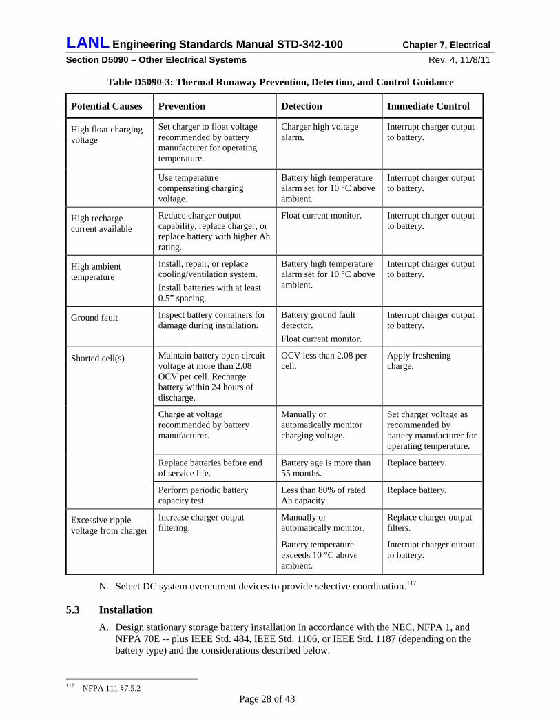
LANL Engineering Standards Manual STD-342-100 Chapter 7, Electrical Section D5090 – Other Electrical Systems Rev. 4, 11/8/11
Page 28 of 43
Table D5090-3: Thermal Runaway Prevention, Detection, and Control Guidance
Potential Causes Prevention Detection Immediate Control
High float charging voltage
Set charger to float voltage recommended by battery manufacturer for operating temperature.
Charger high voltage alarm.
Interrupt charger output to battery.
Use temperature compensating charging voltage.
Battery high temperature alarm set for 10 °C above ambient.
Interrupt charger output to battery.
High recharge current available
Reduce charger output capability, replace charger, or replace battery with higher Ah rating.
Float current monitor. Interrupt charger output to battery.
High ambient temperature
Install, repair, or replace cooling/ventilation system. Install batteries with at least 0.5” spacing.
Battery high temperature alarm set for 10 °C above ambient.
Interrupt charger output to battery.
Ground fault Inspect battery containers for damage during installation.
Battery ground fault detector. Float current monitor.
Interrupt charger output to battery.
Shorted cell(s) Maintain battery open circuit voltage at more than 2.08 OCV per cell. Recharge battery within 24 hours of discharge.
OCV less than 2.08 per cell.
Apply freshening charge.
Charge at voltage recommended by battery manufacturer.
Manually or automatically monitor charging voltage.
Set charger voltage as recommended by battery manufacturer for operating temperature.
Replace batteries before end of service life.
Battery age is more than 55 months.
Replace battery.
Perform periodic battery capacity test.
Less than 80% of rated Ah capacity.
Replace battery.
Excessive ripple voltage from charger
Increase charger output filtering.
Manually or automatically monitor.
Replace charger output filters.
Battery temperature exceeds 10 °C above ambient.
Interrupt charger output to battery.
N. Select DC system overcurrent devices to provide selective coordination.117
5.3 Installation
A. Design stationary storage battery installation in accordance with the NEC, NFPA 1, and NFPA 70E -- plus IEEE Std. 484, IEEE Std. 1106, or IEEE Std. 1187 (depending on the battery type) and the considerations described below.
117 NFPA 111 §7.5.2

LANL Engineering Standards Manual STD-342-100 Chapter 7, Electrical Section D5090 – Other Electrical Systems Rev. 4, 11/8/11
Page 29 of 43
B. Stationary storage battery systems having a free-flowing electrolyte capacity of more than 50 gallons for flooded lead-acid and nickel-cadmium batteries, or a weight of 1000 pounds for valve-regulated, lead-acid (VRLA), lithium-ion, and lithium metal-polymer batteries must meet all applicable requirements of NFPA 1, Chapter 52.
C. Locate battery power system equipment as close together and as near the center of the load as practical to minimize voltage drop and to accommodate maintenance and testing activities.118
D. Locate stationary batteries within a dedicated battery room, protective enclosure, or area accessible only to qualified, authorized persons. A protective enclosure can be either of the following that will adequately protect the battery power system equipment, limit the likelihood of inadvertent contact with energized parts, and limit damage to adjacent equipment from battery fumes or electrolyte spill or spray:
119
1. A dedicated battery room separated from other portions of the building by a minimum of a 1-hour fire barrier
120
2. An approved non-combustible battery cabinet. .
E. Design battery room HVAC system considering operating temperature, adequate ventilation, and the following requirements: 121
1. Maintain yearly average temperature at 77 ºF, 60 ºF to 80 ºF maximum range.
2. Provide 30 percent efficiency air filtration. 3. Temperature must not vary more than 5 ºF from coolest to warmest parts of room. 4. Independently exhaust battery room and discharge outdoors; do not re-circulate battery
room air to other spaces in the building. 5. Design exhaust rate to satisfy either of the following criteria122
• Provide sufficient ventilation (not less than 2 air-changes per hour) to keep hydrogen concentration below 1 percent when battery is on equalizing charge.
:
• Provide continuous ventilation at not less than 1 CFM/sq ft of battery room area or battery cabinet floor area.
A battery room that meets the above ventilation requirements should be considered as non-hazardous; thus special electrical equipment enclosures to prevent fire or explosions should not be necessary.123
6. Provide a suitable combination of exhaust system failure alarm, battery charger interlock, and redundant fan systems to meet the user’s operational continuity and safety analysis requirements.
124
• Non-critical system: Exhaust system flow sensor that will shut down the battery charger(s) and sound a local alarm if the battery room exhaust system fails.
Guidance for possible graded approach configurations includes:
• Important system: Exhaust system flow sensor that will shut down battery charger(s), sound a local alarm, and signal a Facility Management System (FMS) if the battery room exhaust system fails.
• Critical system: Redundant exhaust fans, one fan running continuously to provide the required exhaust rate; flow sensor that will start the second fan, sound a local alarm, and signal a Facility Management System (FMS) if the first exhaust fan fails.
118 IEEE Std 946 §4.5 119 NFPA 70E Article 320 120 NFPA 1 §52.3.3 121 Refer to 5.1 on IEEE Std 484. [This paragraph may be moved to ESM Chapter 6 in the future] 122 NFPA 1 §52.3.6 123 IEEE Std 484 §5.4 124 2009 IFC Sect 608 and IMC 502.3, and lesson learned from a battery room H2 explosion at a large computer/data center on
March 20, 2001 at Sacramento, CA.

LANL Engineering Standards Manual STD-342-100 Chapter 7, Electrical Section D5090 – Other Electrical Systems Rev. 4, 11/8/11
Page 30 of 43
F. Design working spaces around battery power system equipment as required by the NEC.125
G. Locate battery power system components considering floor loading, installation and replacement access, maintenance access, and the following guidance:
126
1. For a system serving over 15 kVA load, provide a battery cabinet with batteries on slide-out trays.
2. For a system serving over 100 kVA load, battery should be rack mounted in dedicated battery room; provide minimum 4 ft aisles between racks.
3. Battery serving safety class or safety significant loads should be rack-mounted in a dedicated battery room rated for design basis event.
4. Limit height of battery racks so top terminal of battery is not more than 53 inches above floor. Provide minimum 15 inches vertical clearance above battery.
5. Use extra flexible cable for external connections to battery terminals. Allow for 6 inches of battery rack movement during an earthquake.
H. Require Class C portable fire extinguisher(s) in the battery room.127
I. Design an emergency eyewash/shower station in each battery room or within 25 feet of a rack-mounted battery.
Coordinate type, size, and placement with the LANL Fire Protection Group.
128
J. Provide battery rooms for vented (flooded) cell batteries with appropriate additional systems such as:
1. Acid absorption pads or pans to contain acid from a ruptured cell. 2. Acid resisting construction. 3. Hydrogen monitoring system. 4. Battery room sink with acid neutralizing basin. 5. Annunciation of ventilation system failure at a monitored location. 6. Spill control kit.
K. Design adequate illumination for the battery area129
1. Protect luminaires from damage by guards, finishes, or isolation.
; refer to Section D5020 of the ESM.
2. Locate lighting switches and receptacles outside the battery area. 3. Provide emergency illumination for the battery location.
L. Specify warning signs inside and outside the battery room or in the vicinity of a battery area as required by NFPA 70E. Refer to Section D5000 of the ESM for information regarding safety signs and to LANL Master Specification Section 26 0553, Electrical Identification for materials and installation methods.130
1. Electrical hazard warning sign: Use arc-flash warning label described in LANL Master Specification Section 26 0553, Identification for Electrical Systems.
2. Chemical hazard warning signs: chemical burns, explosion 3. Notice for personnel to use and wear PPE and apparel 4. Notice prohibiting access to unauthorized personnel
125 NEC Section 110.26. This NEC requirement is repeated here to remind designers that working the NEC working clearances
are required about batteries. 126 NFPA 111 §7.2 127 IEEE Std 484 §4.1 128 OSHA 1926.441(a)(6) and NFPA 70E Article 320 129 NFPA 70E Article 320 130 Ibid

LANL Engineering Standards Manual STD-342-100 Chapter 7, Electrical Section D5090 – Other Electrical Systems Rev. 4, 11/8/11
Page 31 of 43
5.4 Battery System Acceptance Testing and Inspection A. Specify complete acceptance testing and inspection of completed battery power system
systems in accordance with NFPA 111131 and IEEE Std 450.132
1. Require advance notification of acceptance testing to the LANL Electrical AHJ.
2. Tests shall be performed by qualified personnel such as the battery manufacturer’s factory-trained technicians or technicians that are certified in accordance with ANSI/NETA ETT-2000, Standard for Certification of Electrical Testing Technicians.
3. Require a detailed record of acceptance test results on a form suitable for the purpose. 4. Require analysis and recommendations with the acceptance test report.
B. Specify that copies of the acceptance test report and all certifications be delivered to the LANL Electrical AHJ and to the Facility Manager.133
6.0 CABLE TRAY SYSTEMS
6.1 Cable Tray Selection A. Design and specify cable tray and accessories manufactured in accordance with the latest
edition of NEMA VE1–Metal Cable Tray Systems or FG1–Fiberglass Cable Tray Systems.134
B. Use cable tray type suitable for the supported cables.
135
1. Ladder-Type Cable Tray consists of two longitudinal side rails (or the structural equivalent) connected by individual cross members or rungs. Use for large power, control, and communications cables.
2. Ventilated Trough-Type Cable Tray consists of two side rails (or the structural equivalent) with closely spaced supports. Use for small power, control, and communications cables.
3. Solid Bottom Cable Tray consists of two side rails (or the structural equivalent) connected with a corrugated or reinforced solid bottom. Use for power, control, and communications cables requiring maximum electrical or magnetic shielding.
C. Use cable trays that have suitable strength and rigidity to provide adequate support for all contained wiring plus a 200 lb. concentrated load at mid-span.136
1. 6 and 12 in. widths: 50 lbs. per linear foot plus a 200 lb. load at mid-span.
For cable trays installed outdoors, add loading due to snow, ice, and wind. The following are guidelines to suitable minimum working load categories for cable trays:
2. 18 and 24 in. widths: 75 lbs. per linear foot plus a 200 lb. load at mid-span. 3. 30 and 36 in. widths: 100 lbs. per linear foot plus a 200 lb. load at mid-span.
D. Use cable trays made of corrosion-resistant material or adequately protected from corrosion that may be encountered in use; refer to manufacturer’s corrosion resistance data. Some of the commonly available materials and finishes are listed below in approximate order of increasing installed costs:137
131 NFPA 111, 7.6 132 IEEE Std 450 Chapters 5 and 6 133 Acceptance tests will provide baseline data for the LANL battery maintenance program. 134 NEMA VE1 and FG1 are the industry standards for metal and fiberglass cable tray. 135 Descriptions of cable tray types are from NEMA VE1. Recommended uses are from manufacturer’s data. 136 Although walking or standing on cable tray is not recommended by cable tray manufacturers and OHSA regulations, it
happens. 137 Corrosion resistance criteria are from manufacturer’s literature.
LANL Engineering Standards Manual STD-342-100 Chapter 7, Electrical Section D5090 – Other Electrical Systems Rev. 4, 11/8/11
Page 32 of 43
1. Aluminum alloy 6063-T6. Use for most outdoor or indoor applications. 2. Carbon steel mill galvanized. Use for non-corrosive indoor applications. 3. Carbon steel hot dip galvanized AFTER fabrication per ASTM A123. Use for non-
chemical outdoor and industrial indoor applications. 4. Aluminum or steel coated with 15 mils of PVC. Use in chemical environments. 5. Stainless steel type 304. Use in severe chemical environments. 6. Stainless steel type 316. Use in severe chemical environments. 7. Fiberglass with polyester fire-retardant resin system type FR-P. Use where electrical
isolation is required or in severe chemical environments. 8. Fiberglass with vinyl ester fire-retardant resin type FR-VE. Use in severe chemical
environments.
E. Refer to LANL Master Specification Section 26 0536, Cable Trays for Electrical Systems, for material and installation requirements.
6.2 Cable Tray Installation
A. Design installation of cable tray in accordance with the NEC, NEMA VE-2 – “Metal Cable Tray Installation Guidelines,” LMS Section 26 0536, and the LANL ESM.138
B. Require that sufficient space be provided and maintained above and beside cable trays to permit access for installing and maintaining cables.
Refer to Section D5000 of this chapter for additional requirements for nuclear facilities.
139
1. Locate cable trays not less than 12 inches below building structure, suspended mechanical equipment, piping, ductwork, and other cable trays that would impede access to the cable tray(s).
2. Consider center hung tray supports or bracket supports to improve access to the tray for installing cables.
C. Design cable tray supports based on the weight of the cable tray loaded to maximum cable capacity permitted by the NEC plus a 200 lb concentrated load at mid-span plus applicable snow, ice, and wind loads.
D. Design cable tray supports plus longitudinal and transverse seismic bracing as required by the International Building Code, ASCE 7, and Chapter 5 of the LANL ESM.
1. Consult a qualified structural engineer. 2. Figure D5090-5 shows a typical cable tray seismic brace. 3. Refer to LANL Master Specification Section 26 0548, Vibration and Seismic Controls
for Electrical Systems for material and installation requirements.
E. In stacked tray installations, separate voltages; locate the lowest voltage cables in the bottom tray and succeeding higher voltage cables in ascending order of trays.140
138 NEMA VE-2 is a practical guide for the proper installation of steel and aluminum cable trays. 139 Requirement from NEC Section 392.6(I) is repeated for emphasis. 140 Table tray stacking recommended practice is in IEEE Std. 141 Section 12.5.5.
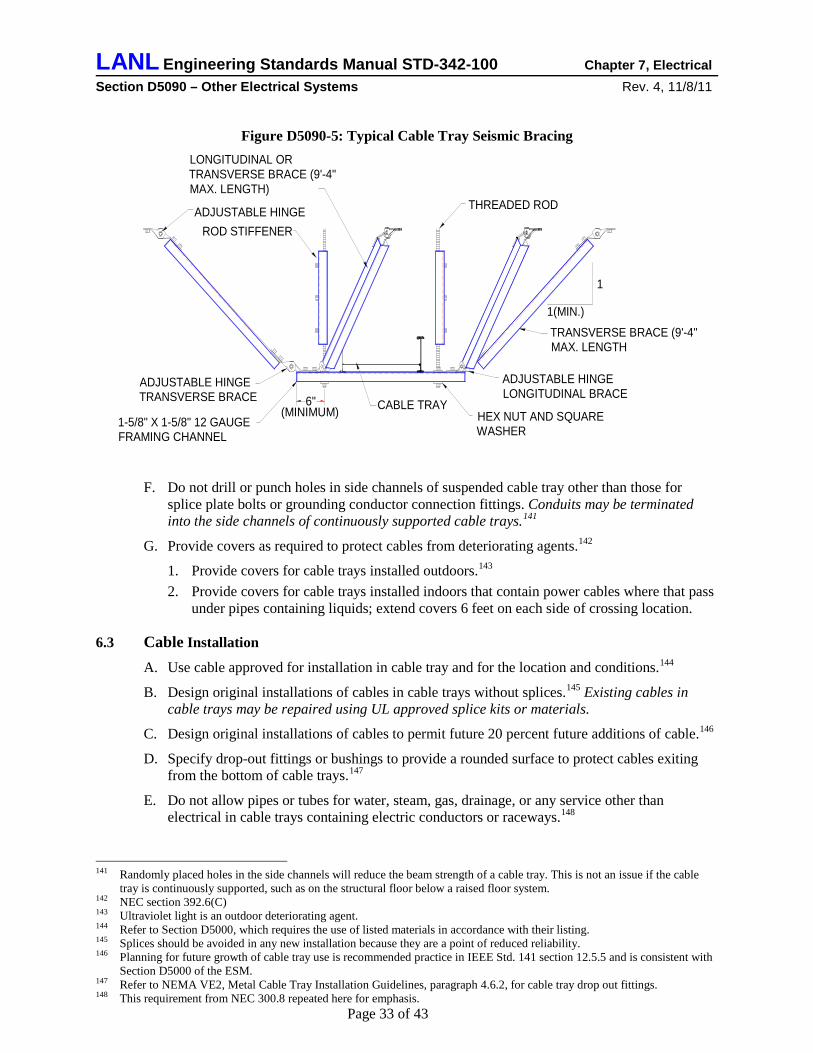
LANL Engineering Standards Manual STD-342-100 Chapter 7, Electrical Section D5090 – Other Electrical Systems Rev. 4, 11/8/11
Page 33 of 43
Figure D5090-5: Typical Cable Tray Seismic Bracing
1
ADJUSTABLE HINGELONGITUDINAL BRACE
HEX NUT AND SQUAREWASHER
ADJUSTABLE HINGETRANSVERSE BRACE
1-5/8" X 1-5/8" 12 GAUGEFRAMING CHANNEL
ADJUSTABLE HINGE
LONGITUDINAL ORTRANSVERSE BRACE (9'-4"MAX. LENGTH)
THREADED ROD
(MINIMUM)6"
ROD STIFFENER
CABLE TRAY
TRANSVERSE BRACE (9'-4"MAX. LENGTH
1(MIN.)
F. Do not drill or punch holes in side channels of suspended cable tray other than those for splice plate bolts or grounding conductor connection fittings. Conduits may be terminated into the side channels of continuously supported cable trays.141
G. Provide covers as required to protect cables from deteriorating agents.
142
1. Provide covers for cable trays installed outdoors.
143
2. Provide covers for cable trays installed indoors that contain power cables where that pass under pipes containing liquids; extend covers 6 feet on each side of crossing location.
6.3 Cable Installation
A. Use cable approved for installation in cable tray and for the location and conditions.144
B. Design original installations of cables in cable trays without splices.
145
C. Design original installations of cables to permit future 20 percent future additions of cable.
Existing cables in cable trays may be repaired using UL approved splice kits or materials.
146
D. Specify drop-out fittings or bushings to provide a rounded surface to protect cables exiting from the bottom of cable trays.
147
E. Do not allow pipes or tubes for water, steam, gas, drainage, or any service other than electrical in cable trays containing electric conductors or raceways.
148
141 Randomly placed holes in the side channels will reduce the beam strength of a cable tray. This is not an issue if the cable
tray is continuously supported, such as on the structural floor below a raised floor system. 142 NEC section 392.6(C) 143 Ultraviolet light is an outdoor deteriorating agent. 144 Refer to Section D5000, which requires the use of listed materials in accordance with their listing. 145 Splices should be avoided in any new installation because they are a point of reduced reliability. 146 Planning for future growth of cable tray use is recommended practice in IEEE Std. 141 section 12.5.5 and is consistent with
Section D5000 of the ESM. 147 Refer to NEMA VE2, Metal Cable Tray Installation Guidelines, paragraph 4.6.2, for cable tray drop out fittings. 148 This requirement from NEC 300.8 repeated here for emphasis.
LANL Engineering Standards Manual STD-342-100 Chapter 7, Electrical Section D5090 – Other Electrical Systems Rev. 4, 11/8/11
Page 34 of 43
7.0 SIGNAL REFERENCE GRID A. Design a signal reference grid (SRG) for computer room raised floor areas. Refer to IEEE
Std. 1100–Powering and Grounding Electrical Equipment for additional design guidance.
B. Use one or a combination of the following systems:
1. Pre-fabricated grid of 2 inches wide by 26 gauge copper strips on 2-foot centers with all crossover connections factory welded. Bond every sixth raised floor pedestal to the SRG using 6 AWG grounding conductor.
2. Raised floor pedestal system with bolted down galvanized steel horizontal stringers. 3. 2 ft X 2 ft grid of bare No. 6 AWG conductors clamped to raised floor pedestals.
C. Specify bonding of structural steel columns, pipes, conduits, ducts, etc. passing through the SRG to the SRG using 6 AWG grounding conductor.
D. Specify bonding of computer equipment, power panels, and computer distribution units to the SRG using low impedance risers (LIR).
1. Install LIR as 2 inches wide, 26 gauge copper strips or 1 inch wide flexible braided copper straps.
2. Do not connect the LIR to the SRG conductor closest to the outside edge of the SRG. 3. Keep the LIR as short as possible. 4. If LIR exceeds 24 inches, install two parallel LIRs connected to opposite corners of the
equipment. Make the second LIR 20 percent to 40 percent longer than the first.
8.0 LIGHTNING PROTECTION SYSTEMS
8.1 Criteria A. Perform and document a lightning risk assessment as described in the lightning risk
assessment annex of NFPA 780 for each structure that meets any of the following criteria:149
1. Contains facilities for the use, processing, and storage of radioactive, explosive, and similarly hazardous materials.
150
2. Extends more than 50 feet above adjacent structures or terrain.
151
3. Has a total floor area greater than 5000 square feet or contains equipment valued over $3 million
152, critical operating equipment, or services essential to public safety.153
4. Is an open shelter (e.g. bus stop personnel shelter) that is not in the “zone of protection” of a nearby taller structure.
154
B. For the lightning risk assessment use a flash density of 8 flashes/km2/year.
155
C. Design a lightning protection system (LPS), including surge protection equipment, if the lightning risk assessment indicates that the calculated “expected lightning stroke frequency to
149 Criteria from DOE-STD-1066-99, Fire Protection Design Criteria, Section 12. 150 DOE G 420.1-1 requires that lighting protection be considered for buildings and structures that contain, process, and store
radioactive, explosive, and similarly hazardous materials. 151 NFPA 780 risk index increases significantly for tall structures. 152 DOE G420.1-3 Section 4.19.3 153 NFPA 780 risk index increases significantly for structures having high-value contents, critical operating equipment, or
essential services. 154 NFPA 780 §4.7; structures located within a “zone of protection” are protected by the taller structure. 155 Based on flash density map from Global Atmospherics that covers a 30-mile radius centered on LANL TA-3.

LANL Engineering Standards Manual STD-342-100 Chapter 7, Electrical Section D5090 – Other Electrical Systems Rev. 4, 11/8/11
Page 35 of 43
the structure” (Nd) is greater than the calculated “tolerable lightning frequency to the structure” (Nc).156
D. For structures
not
1. NFPA 780–Standard for the Installation of Lightning Protection Systems, supplemented by UL 96A–Installation Requirements for Lightning Protection Systems, and LPI 175–LPI Standard of Practice,
used for the storage or handling of explosives, design and install the LPS in accordance with:
2. LANL Master Specifications Section 26 4100 Facility Lightning Protection, 3. And this Section of the LANL Engineering Standards Manual.
E. For structures used for the storage or handling of explosives, meet the requirements of DOE M 440.1-1A–Explosives Safety Manual and NFPA 780, Chapter 8.
1. Design and install the LPS for explosives handling and storage facilities according to the requirements described above plus: • DOE M 440.1-1A–Explosives Safety Manual • MIL-HDBK 1004/6–Lightning Protection,157
• LANL Master Specifications Section 26 4115 Lightning Protection for Explosive Facilities, and
• This Section of the LANL Engineering Standards Manual. 2. The acceptable types of LPSs are mast, catenary, integral air terminal, and Faraday cage
or Faraday-like shield systems. Faraday cage or Faraday-like shield systems (in conjunction with a Franklin-type system to protect the structure) are preferred for new explosives handling and storage facilities.158
F. For open shelters, design and install the LPS in accordance with:
The Faraday cage is intended to protect the interior of the structure and its contents from high electric fields and resultant arcs; the Franklin type system (NFPA 780 mast, catenary, and integral air terminal systems) is intended to protect the structure from fire, perforation, and other damage.
1. NFPA 780–Standard for the Installation of Lightning Protection Systems, supplemented by the NFPA annex “Protection for Picnic Grounds, Playgrounds, Ball Parks, and Other Open Places,”159
2. LANL Master Specifications Section 26 4100, Facility Lightning Protection, and
3. This Section of the LANL Engineering Standards Manual.
G. Extend an existing LPS to any building addition if the addition is not within the existing LPS “zone of protection”. Determine the “zone of protection” using the “rolling sphere” concept described in NFPA 780.160
1. For structures
not
2. For structures used for the storage or handling of explosives use a rolling sphere with a radius of 100 ft.
used for the storage or handling of explosives use a rolling sphere with a radius of 150 ft.
161
156 NFPA 780 Annex L (2011 Edition) 157 MIL-HDBK 1004/6 addresses the design of lightning protection for explosives facilities much more comprehensively than
NFPA 780. 158 DOE M 440.1-1A, DOE Explosives Safety Manual, Chapter X 159 Annex G in NFPA 780 establishes requirements and good practice guidelines for providing protection to personnel in open
shelters. Design issues addressed include reducing step potential, reducing touch potential, and reducing sideflash to personnel.
160 NFPA 780 §4.7.3 161 NFPA 780 §8.2.1 (2011 Edition)

LANL Engineering Standards Manual STD-342-100 Chapter 7, Electrical Section D5090 – Other Electrical Systems Rev. 4, 11/8/11
Page 36 of 43
H. For new installations or major renovations, require that the installer furnish shop drawings showing LPS, installation details, and list of materials.
I. Use a qualified lightning protection system designer to design the LPS. Installer must have either a current LPI Master Installer certification or current UL listing (Category OWAY) for Lightning Protection Installation.162
8.2 Grounding System
A. For new structures design an LPS ground ring electrode (counterpoise), minimum 1/0 AWG163 (4/0 AWG164 for Class II systems) bare copper, at a distance of five feet from the foundation and 3 feet below grade165. Locate at least 6 feet from any electrical system or communications system ground electrode.166 Backfill with a non-corrosive ground enhancement material to lower resistance to earth.167
1. Structures
Design grounding electrode system to obtain the following ground resistance:
not2. Explosives handling and storage facilities: 10 ohms or less.
used for the storage or handling of explosives: 25 ohms or less 168
B. For existing structures verify the integrity and measure the ground resistance of the existing LPS grounding electrode.
1. Verify that the LPS grounding electrode is a separate electrode from that used for the building electrical system.
2. Design supplemental grounding electrodes to obtain an LPS ground resistance of 25 ohms or less for ordinary structures and 10 ohms for or less for explosives handling and storage facilities. Electrolytic ground rods installed in accordance with the manufacturer’s instructions may be used for such supplemental electrodes.
C. Bond the LPS counterpoise to the main grounding electrode bar at the service entrance.169
D. For open shelters, in addition to the LPS counterpoise ground ring described above, design the following supplemental grounding and bonding:
1. Design radial electrodes connected to each exterior corner of the counterpoise ground ring. Design additional radial electrodes where down conductors connect to the counterpoise ground ring between the corners. Design each radial electrode in a separate trench extending outward from the corner of the ground ring. Each radial shall be not less than 12 ft long and shall diverge at an angle not greater than 90 degrees. Radials shall be the same material and depth as the counterpoise ground ring.170
2. Design a down conductor at each corner of the structure.
171 Design additional down conductors so the average spacing between down conductors does not exceed 100 ft.172
162 Installer certification or listing assures national standards are met including those set forth in NFPA 780 and UL 96A.
Certification places requirements on design, materials, workmanship, and inspection. 163 1/0 AWG is a close match to the outside diameter of the main conductor for Class I systems. 164 4/0 AWG is a close match to the outside diameter of the main conductor for Class II systems. 165 Ground ring should be located below the frost line, generally accepted as 36 inches at LANL. 166 Separation is required so one grounding electrode will not reduce the effectiveness of the other. 167 In dry areas and in soils with high resistivity, such as the volcanic tuff at LANL, backfill materials such as bentonite or coke
breeze improve the performance of grounding electrodes. They do this through a combination of increasing the soil moisture content, decreasing the resistance of the electrode to soil interface, and increasing the effective diameter of the electrode.
168 MIL-HDBK 1004/6 §4.2.1 169 NEC §250.106 170 NFPA 780 §4.13.5 171 NFPA 780 §G.1.1.2(1) 172 NFPA 780 §4.9.10

LANL Engineering Standards Manual STD-342-100 Chapter 7, Electrical Section D5090 – Other Electrical Systems Rev. 4, 11/8/11
Page 37 of 43
Bond down conductors to the top and bottom of the reinforcing steel in concrete columns and to structural metal columns and to the counterpoise ground ring.173
3. Specify electrical insulation around columns and down conductors from the floor to 8 ft above the floor. Use material that provides not less than 600 volts electrical insulation and is resistant to impact, climatic conditions, and ultraviolet light.
174
4. Design a grounding grid under the floor of the structure and extending to not less than 33 inches outside the perimeter of the structure.
175 Use the same material as the counterpoise ground ring. Spacing between conductors shall be not more than 3.3 ft and depth of the grid shall be no less than 6 inches and no greater than 18 inches. Interconnect grid conductors at the perimeter and at each intersection.176 Connect ground grid to counterpoise ground ring at each corner and at additional points so average spacing between connection points is less than or equal to 30 ft.177
8.3 Installation
A. For new construction use a maximum air terminal spacing of 20 feet around the perimeter of the roof.178
B. To the maximum extent possible, locate roof conductors so they will be visible for inspection and testing.
Avoid long air terminals that overturn adhesive bases or require supplemental supports.
C. Locate down conductors either concealed or exposed as permitted by NFPA 780.
1. Avoid the use of through-roof connectors; make connections in parapet walls. 2. To facilitate verification of connections to the LPS ground, design an accessible down
conductor disconnect in each down conductor except the one nearest the electrical service entrance. Disconnects for concealed down conductors may be located behind access panels or cover plates.
D. Bond metallic piping systems (water, gas, sewer, etc) entering the building to the LPS.179
E. Use the following LPS connection methods unless otherwise required by this Section or applicable codes:
1. Exothermic weld connections for underground or concealed connections of dissimilar materials.
2. Exothermic weld or IEEE Std. 837 compression connectors for underground or concealed connections of like materials. Do not use compression connections for rope lay lightning conductor connections or for ground rod connections.
3. Exothermic weld or bolted connections for accessible connections. F. Prohibit painting or covering of LPS bonds or connections.180
G. Locate strike termination devices as close as possible to ridge ends or edges; and the outside corners of flat or gently sloping roofs.
173 NFPA 780 §4.9.13 174 NFPA 780 §G.1.1.2(2) 175 NFPA 780 §G.1.1.2 and §G.1.1.3; extension of ground grid outside the structure is to reduce touch and step potential
hazards to personnel entering, exiting or standing adjacent to the structure. 176 NFPA 780 §G.1.1.3(2) 177 NFPA 780 §G.1.1.3(3) 178 20-ft spacing allows use of air terminals that are shorter than 24 inches that do not require supplemental support. Refer to
NFPA 780 paragraph 4.6.2. 179 UL 96A §9.4.1 and §10.4.1 180 NFPA 780 §8.3.5 (2011 Edition); this requirement for explosives facilities is extended to all LANL facilities.- Paint, roofing
tar, or other covering makes visual inspection for connection integrity difficult or impossible.

LANL Engineering Standards Manual STD-342-100 Chapter 7, Electrical Section D5090 – Other Electrical Systems Rev. 4, 11/8/11
Page 38 of 43
8.4 Surge Protection A. Design and specify surge protection for electrical power systems, control, signaling, antenna,
and alarm circuits entering and exiting all structures, including structures that may not have LPS on the roof. 181
1. NFPA 780 – Standard for the Installation of Lightning Protection Systems
Comply with the following: 182
2. National Electrical Code Article 285, ,
3. IEEE Std 1100 – Powering and Grounding Electronic Equipment part 8.6, 4. LMS Section 26 4300 – Surge Protective Devices.
B. For power systems provide surge protective devices (SPDs) that are NRTL-listed per UL 1449 Third Edition, classified as SPD Type 1, and are suitable for the application environments at the following locations:
1. The service entrance equipment for each electrical service entering the structure.183
2. Each transfer switch that is connected to an outdoor generator.
183 3. Each panelboard and motor control center with an electrical feeder, branch circuit, or
control circuit extending to a location having exposure to lightning.184
4. Each panelboard and motor control center with an electrical feeder, branch circuit, or line voltage control circuit that leaves the structure and extends more than 100 ft to another structure.
Examples include circuits to parking lot lighting and to roof-mounted HVAC equipment.
185
Where practical the SPDs should be factory installed and integrated into the distribution equipment.
C. For conductive-media fire alarm, security, and similar low-voltage systems provide surge protective devices (SPDs) that are NRTL-listed per UL 497B and are suitable for the application environments at the following locations:
1. Each circuit entering the structure.186
2. Each circuit extending to a location having exposure to lightning. Examples include low-voltage control circuits to roof-mounted HVAC equipment.
3. Each circuit that leaves the structure and extends more than 100 ft to another structure.185
D. For coaxial cables for antenna and camera systems provide surge protective devices (SPDs) that are NRTL-listed per UL 497C and are suitable for the application environments at the following locations. Where several such cables enter at one location, provide an enclosure with ground connection provisions for the SPDs.
1. Each cable entering the structure.186
2. Each cable extending to a location having exposure to lightning.184 Examples include low-voltage control circuits to roof-mounted HVAC equipment.
3. Each cable that leaves the structure and extends more than 100 ft to another structure.185
E. Verify that suitable SPDs have or will be installed on each telecommunications line that enters the structure187
181 Refer to NFPA 780 §4.18 and IEEE Std 1100 §8.6. 182 It is acknowledged that Table 4.18.4 in NFPA 780-2010 contains errors, inconsistencies, and requirements that are not
attainable using commercially available SPDs. 183 Refer to NFPA 780 §4.18.2.1. 184 Refer to IEEE Std. 1100 §8.6.8. 185 Refer to NFPA 780 §4.18.2.3. 186 Refer to NFPA 780 §4.18.2.2.
.

LANL Engineering Standards Manual STD-342-100 Chapter 7, Electrical Section D5090 – Other Electrical Systems Rev. 4, 11/8/11
Page 39 of 43
F. At explosives handling and storage facilities, all electrical power circuits, communications circuits, shielded cables, etc. must be run underground in metal conduit for a minimum of 50 feet before they enter the explosives facility188
G. Refer to LMS Section 26 4300, Surge Protective Devices for material and installation requirements.
. SPDs for power circuits, communications circuits, shielded cables, etc. must be installed at the transition to underground conduit, outside the 50-ft limit.
8.5 Acceptance Inspection Acceptance inspection will be by the LANL lightning protection subject matter expert (SME).
9.0 SOLAR PHOTOVOLTAIC (PV) SYSTEMS
9.1 Stand-Alone PV Systems A. Design stand-alone solar photovoltaic (PV) systems189
B. A stand-alone PV system will include one or more PV modules, a charge controller, one or more storage batteries, DC overcurrent protective equipment, DC surge protective devices, and DC distribution wiring. There may be one or more small inverters to directly support equipment that requires 60 Hz AC power.
for powering systems such as remote experiments, environmental monitoring equipment, or communications apparatus at locations where utility power is not readily available.
C. Select and size stand-alone PV system components in accordance with the following standards:
1. IEEE Std 1013, IEEE Recommended Practice for Sizing Lead-Acid Batteries for Stand-Alone Photovoltaic (PV) Systems
2. IEEE Std 1361, IEEE Guide for Selection, Charging, Test, and Evaluation of Lead-Acid Batteries Used in Stand-Alone Photovoltaic (PV) Systems
3. IEEE Std 1526, IEEE Recommended Practice for Testing the Performance of Stand-Alone Photovoltaic Systems
4. IEEE Std 1562, IEEE Guide for Array and Battery Sizing in Stand-Alone Photovoltaic (PV) Systems.
9.2 Interactive PV Systems A. Design interactive solar photovoltaic (PV) systems190 to meet User’s requirements for
providing renewable-energy to facility structures to partially offset the use of utility electric power (and to obtain LEED points.191
B. An interactive PV system will include multiple PV modules arranged and connected to form one or more arrays, metering, utility interactive inverter(s), AC and DC overcurrent protective equipment, AC and DC surge protective devices, AC and DC distribution wiring, connection to the 60 Hz facility power distribution system, and possibly storage batteries and charge controller(s),.
)
187 Refer to NFPA 780 §4.18.6. 188 Refer to NFPA 780 §8.7. 189 Refer to NEC Section 690.2. 190 Refer to NEC Section 690.2. 191 LEED Energy and Atmosphere Credit 2 (On-Site Renewable Energy): LEED awards 1 to 7 points for
generating 1 to 13 percent of the building’s annual energy using PV.

LANL Engineering Standards Manual STD-342-100 Chapter 7, Electrical Section D5090 – Other Electrical Systems Rev. 4, 11/8/11
Page 40 of 43
C. Select and size interactive PV system components in accordance with the following standards and documents:
1. IEEE Std 928, IEEE Recommended Criteria for Terrestrial Photovoltaic Power Systems,
2. IEEE Std 929, IEEE Recommended Practice for Utility Interface of Residential and Intermediate Photovoltaic (PV) Systems,
3. IEEE Std 937, IEEE Recommended Practice for Installation and Maintenance of Lead-Acid Batteries for Photovoltaic (PV) Systems,
4. IEEE Std 1661, IEEE Guide for Test and Evaluation of Lead-Acid Batteries Used in Photovoltaic (PV) Hybrid Power Systems,
5. ASHRAE 4782 – Techno-Economic Analysis of a Large-Scale Rooftop Photovoltaic System. This paper provides useful tools for analyzing alternative PV systems and for optimizing PV systems.
9.3 PV System Products A. Use PV system components that are NRTL listed to the following standards:
1. UL 1703 – Flat-Plate Photovoltaic Modules and Panels,
2. UL 1741 – Inverters, Converters, Controllers, and Interconnection System Equipment for Use with Distributed Energy Resources.
B. De-rate PV system components as required to assure satisfactory performance in the environmental conditions at the location where the PV system will be located. Environmental conditions that must be considered include but are not limited to:
1. Altitude, 7500 ft.
2. Temperature extremes, -16 °F to 95 °F for Los Alamos, -29 °F to 100 °F for White Rock.
3. Dust and debris such as pine needles that collect on PV panels.
4. Feasible PV array orientations.
5. Shading of PV array by terrain, trees, or structures.
9.4 Installation Design A. Comply with the National Electrical Code, specifically the following articles that address PV
systems and utility-interactive systems:
1. Article 690 – Solar Photovoltaic (PV) Systems,
2. Article 705 – Interconnected Electric Power Production Sources.
B. Locate, orient, and arrange PV array to optimize performance.
1. To the extent possible, locate the PV array where it will be fully illuminated with no shadows192
192 Photovoltaic cell electrical output is extremely sensitive to shading. When even a small portion of a cell, module, or array is
shaded, while the remainder is in sunlight, the output falls dramatically due to internal “short-circuiting” (the electrons reversing course through the shaded portion of the
(including self-shading) from 9:00 AM until 4:00 PM (solar time).
p-n junction). If the current drawn from the series string of cells is no greater than the current that can be produced by the shaded cell, the current (and so power) developed by the string is limited. If enough voltage is available from the rest of the cells in a string, current will be forced through the cell by breaking down the junction in the shaded portion. This breakdown voltage in common cells is between 10 and 30 volts. Instead of adding to the power produced by the panel, the shaded cell absorbs power, turning it into heat. Since the reverse voltage of a shaded cell is much greater than the forward voltage of an illuminated cell, one shaded cell can absorb the power of many other cells in the string, disproportionately affecting panel output. For example, a shaded cell may drop 8

LANL Engineering Standards Manual STD-342-100 Chapter 7, Electrical Section D5090 – Other Electrical Systems Rev. 4, 11/8/11
Page 41 of 43
2. Position PV array (azimuth and tilt angle) to optimize total annual PV system energy production for the application.193
C. Select PV panel technology
194
1. Stand-alone systems: PV panels selected based on the electrical load and the space available for the PV array.
to make cost-effective use of available PV array space. Use the following guidance:
2. Interactive systems for facilities, typically roof-mounted: PV panels with monocrystalline silicon cells to maximize use of limited array space.
3. Interactive systems at the utility level – typically large and ground-mounted: PV panels with polycrystalline silicon cells or thin-film cells to achieve an appropriate trade-off between efficiency and first cost.
D. For interactive systems, select and match the PV array(s) and inverter(s) to optimize efficiency, reliability, annual AC energy output, and life cycle cost.
1. In cases where the PV system output is planned to approximately match the building electrical load, optimize the PV array size so the hourly PV system output will closely match the building hourly electrical load, and the electricity “sold” to the power grid will be minimized.193
2. Determine the number of PV arrays and corresponding inverters to cost-effectively improve the PV system reliability and to maximize annual AC power production.195
3. Match the PV array and the corresponding inverter so the PV array output will be within the current, voltage, and power limits of the inverter, and so the grid-connected PV system economic performance will be optimized.
196
4. The temperature-adjusted PV array voltage must remain within the inverter limits at the historical record high and record low temperatures for the location where the PV system will be installed. Adjust the extreme high temperature to account for mid-day solar heat gain based on PV panel mounting as follows:
• Mounted on the roof plane or on racks with less than 10 degrees slope above the roof plane: Add 35 °C (63 °F).
• Rack mounted with more than 10 degrees slope above roof plane: Add 30 °C (54 °F).
• Ground mounted on racks or poles: Add 25 °C (45 °F).
volts, instead of adding 0.5 volts, at a particular current level, thereby absorbing the power produced by 16 other cells. Therefore it is extremely important that a PV installation is not shaded at all by trees, architectural features, flag poles, or other obstructions. Most modules have bypass diodes between each cell or string of cells that minimize the effects of shading and only lose the power of the shaded portion of the array (The main job of the bypass diode is to eliminate hot spots that form on cells that can cause damage to the array.).
193 Refer to ASHRAE: 4782 – Techno-Economic Analysis of a Large-Scale Rooftop Photovoltaic System. 194 Three PV cell technologies were in widespread commercial PV panel production in 2011:
• Monocrystalline silicon (c-Si): highest energy conversion efficiency, highest cost. • Polycrystalline silicon (mc-Si): slightly lower energy conversion efficiency than c-Si, and lower cost. • Thin film (a-Si or CIGS): lowest cost, lowest energy conversion efficiency, greatest weight per unit area.
195 Refer to Pregelj, Begovic, and Rohatgi: “Impact of Inverter Configuration on PV System Reliability and Energy Production,” 2001, Georgia Institute of Technology.
196 Refer to Mondol: “Sizing of Grid-Connected Photovoltaic Systems,” 2007, The International Society for Optical Engineering.

LANL Engineering Standards Manual STD-342-100 Chapter 7, Electrical Section D5090 – Other Electrical Systems Rev. 4, 11/8/11
Page 42 of 43
E. Use the following wiring materials and methods197
1. Metallic conduits and boxes,
for PV systems:
2. Metallic wireway systems,
3. Copper conductors with XHHW-2 insulation.
F. Design grounding and bonding for PV systems in accordance with NEC Article 690 and the following additional criteria:
1. Install a green insulated equipment grounding conductor in each PV system raceway for AC or DC circuits. Increase equipment grounding conductor size in proportion to increases in power conductors to limit voltage drop.
2. Bond PV modules using 6 AWG or larger copper conductors. Make connections to PV module frames using connectors that are NRTL-listed for outdoor or direct-burial use.
G. Design wiring system to limit full-load voltage drops198
1. 2 percent or less from the farthest PV module to the inverter DC input.
as follows:
2. 2 percent or less from the farthest PV module to the DC loads bus.
3. 2 percent or less from the inverter AC output to the facility AC power panelboard.
H. Design both stationary battery and surge protection systems and installations in accordance with those subsections in this document.
I. Design structural supports for PV panels, arrays, and components in accordance with LANL ESM Chapter 5 – Structural and the following codes and standards:
1. Uniform Building Code Section 1509 – Rooftop Structures,
2. ASCE 7 Chapter 13 – Seismic Design Requirements for Nonstructural Components,
3. ASCE Chapter 15 – Seismic Design Requirements for Non-building Structures,
4. ASCE Chapter 29 – Wind Loads on Other Structures and Building Appurtenances.
J. For interactive PV systems, locate freeze-proof water hydrant(s) adjacent to each PV array so all PV panels can be accessed with a 50 ft garden hose for cleaning.199
197 Wiring methods based on the expected long service life of PV panels and other components in a hot outdoor location. 198 Because each installed watt of PV costs approximately $5.00, it is wasteful to dissipate energy to heat wires
when the cost of larger wires is minimal compared with the cost of PV modules. Voltage drop is often the determining factor in wire sizing particularly for systems operating below 100 Volts. Voltage drop is not a safety issue; therefore it is not covered in great detail in the NEC. However PV systems with excessive voltage drop are inefficient and perform poorly.
199 Sunlight is absorbed by dust, snow, or other impurities on the surface of the PV module. This reduces the amount of light that actually strikes the PV cells by as much as half. Maintaining a clean PV module surface will increase output performance over the life of the module.

LANL Engineering Standards Manual STD-342-100 Chapter 7, Electrical Section D5090 – Other Electrical Systems Rev. 4, 11/8/11
Page 43 of 43
K. Document the design of the PV system with the following:
1. Design description and calculations for the selection and appropriate de-rating of proposed major components (PV modules, DC circuit combiner, charge controller, batteries, inverters, etc); include data sheets for the major components.
2. Specifications for proposed major PV system components,
3. Electrical schematic showing interconnection of major components,
4. Plans showing location and arrangement of major PV system components,
5. Calculations for selecting PV system conductors,
6. For interactive PV systems, provide calculations estimating annual kWh delivered to the facility 60 Hz power system.
7. Structural calculations, drawings, and specifications for anchoring and bracing of PV system components.