Thorlabs.com - InGaAs Free-Space Amplified Photodetectors€¦ · · 2018-03-13transimpedance...
17
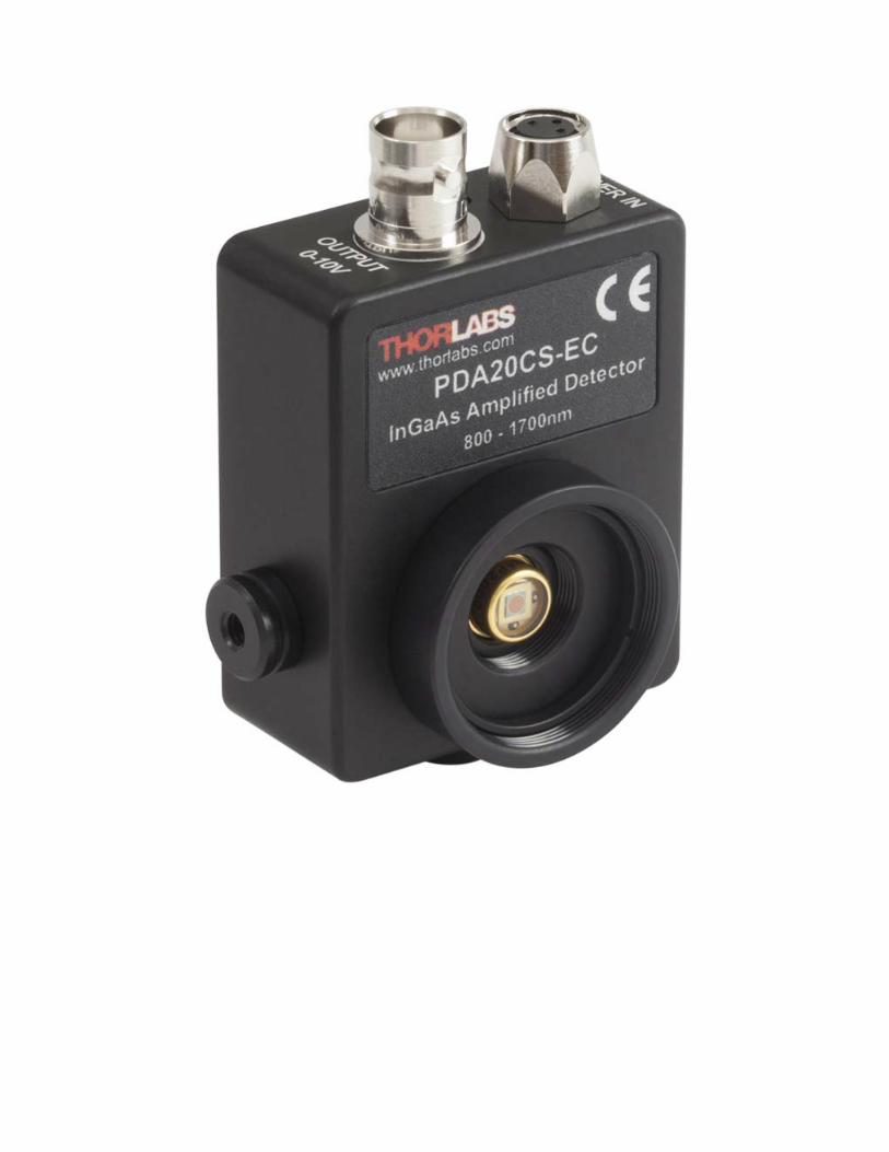
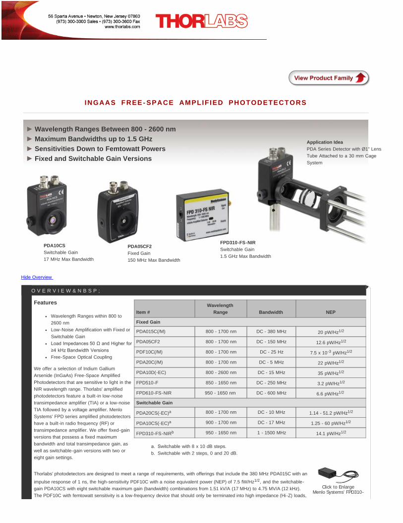
Thorlabs.com - InGaAs Free-Space Amplified Photodetectors INGAAS FREE-SPACE AMPLIFIED PHOTODETECTORS Hide Overview Item # Wavelength Range Bandwidth NEP Fixed Gain PDA015C(/M) 800 - 1700 nm DC - 380 MHz 20 pW/Hz 1/2 PDA05CF2 800 - 1700 nm DC - 150 MHz 12.6 pW/Hz 1/2 PDF10C(/M) 800 - 1700 nm DC - 25 Hz 7.5 x 10 -3 pW/Hz 1/2 PDA20C(/M) 800 - 1700 nm DC - 5 MHz 22 pW/Hz 1/2 PDA10D(-EC) 800 - 2600 nm DC - 15 MHz 35 pW/Hz 1/2 FPD510-F 850 - 1650 nm DC - 250 MHz 3.2 pW/Hz 1/2 FPD610-FS-NIR 950 - 1650 nm DC - 600 MHz 6.6 pW/Hz 1/2 Switchable Gain PDA20CS(-EC) a 800 - 1700 nm DC - 10 MHz 1.14 - 51.2 pW/Hz 1/2 PDA10CS(-EC) a 900 - 1700 nm DC - 17 MHz 1.25 - 60 pW/Hz 1/2 FPD310-FS-NIR b 950 - 1650 nm 1 - 1500 MHz 14.1 pW/Hz 1/2 witchable with 8 x 10 dB steps. Switchable with 2 steps, 0 and 20 dB. Click to Enlarge Menlo Systems’ FPD310- Features Wavelength Ranges within 800 to 2600 nm Low-Noise Amplification with Fixed or Switchable Gain Load Impedances 50 Ω and Higher for ≥4 kHz Bandwidth Versions Free-Space Optical Coupling We offer a selection of Indium Gallium Arsenide (InGaAs) Free-Space Amplified Photodetectors that are sensitive to light in the NIR wavelength range. Thorlabs' amplified photodetectors feature a built-in low-noise transimpedance amplifier (TIA) or a low-noise TIA followed by a voltage amplifier. Menlo Systems' FPD series amplified photodetectors have a built-in radio frequency (RF) or transimpedance amplifier. We offer fixed-gain versions that possess a fixed maximum bandwidth and total transimpedance gain, as well as switchable-gain versions with two or eight gain settings. Thorlabs' photodetectors are designed to meet a range of requirements, with offerings that include the 380 MHz PDA015C with an impulse response of 1 ns, the high-sensitivity PDF10C with a noise equivalent power (NEP) of 7.5 fW/Hz 1/2 , and the switchable- gain PDA10CS with eight switchable maximum gain (bandwidth) combinations from 1.51 kV/A (17 MHz) to 4.75 MV/A (12 kHz). The PDF10C with femtowatt sensitivity is a low-frequency device that should only be terminated into high impedance (Hi-Z) loads, OVERVIEW  Wavelength Ranges Between 800 - 2600 nm Maximum Bandwidths up to 1.5 GHz Sensitivities Down to Femtowatt Powers Fixed and Switchable Gain Versions ► ► ► ► PDA10CS Switchable Gain 17 MHz Max Bandwidth Application Idea PDA Series Detector with Ø1" Lens Tube Attached to a 30 mm Cage System PDA05CF2 Fixed Gain 150 MHz Max Bandwidth FPD310-FS-NIR Switchable Gain 1.5 GHz Max Bandwidth
Transcript of Thorlabs.com - InGaAs Free-Space Amplified Photodetectors€¦ · · 2018-03-13transimpedance...
Thorlabs.com - InGaAs Free-Space Amplified Photodetectors
INGAAS FREE - SPACE AMPLIF IED PHOTODETECTORS
Hide Overview
Item #Wavelength
Range Bandwidth NEP
Fixed Gain
PDA015C(/M) 800 - 1700 nm DC - 380 MHz 20 pW/Hz1/2
PDA05CF2 800 - 1700 nm DC - 150 MHz 12.6 pW/Hz1/2
PDF10C(/M) 800 - 1700 nm DC - 25 Hz 7.5 x 10⁻³ pW/Hz1/2
PDA20C(/M) 800 - 1700 nm DC - 5 MHz 22 pW/Hz1/2
PDA10D(-EC) 800 - 2600 nm DC - 15 MHz 35 pW/Hz1/2
FPD510-F 850 - 1650 nm DC - 250 MHz 3.2 pW/Hz1/2
FPD610-FS-NIR 950 - 1650 nm DC - 600 MHz 6.6 pW/Hz1/2
Switchable Gain
PDA20CS(-EC)a 800 - 1700 nm DC - 10 MHz 1.14 - 51.2 pW/Hz1/2
PDA10CS(-EC)a 900 - 1700 nm DC - 17 MHz 1.25 - 60 pW/Hz1/2
FPD310-FS-NIRb 950 - 1650 nm 1 - 1500 MHz 14.1 pW/Hz1/2
witchable with 8 x 10 dB steps.Switchable with 2 steps, 0 and 20 dB.
Click to EnlargeMenlo Systems’ FPD310-
Features
Wavelength Ranges within 800 to2600 nmLow-Noise Amplification with Fixed orSwitchable GainLoad Impedances 50 Ω and Higher for≥4 kHz Bandwidth VersionsFree-Space Optical Coupling
We offer a selection of Indium GalliumArsenide (InGaAs) Free-Space AmplifiedPhotodetectors that are sensitive to light in theNIR wavelength range. Thorlabs' amplifiedphotodetectors feature a built-in low-noisetransimpedance amplifier (TIA) or a low-noiseTIA followed by a voltage amplifier. MenloSystems' FPD series amplified photodetectorshave a built-in radio frequency (RF) ortransimpedance amplifier. We offer fixed-gainversions that possess a fixed maximumbandwidth and total transimpedance gain, aswell as switchable-gain versions with two oreight gain settings.
Thorlabs' photodetectors are designed to meet a range of requirements, with offerings that include the 380 MHz PDA015C with an
impulse response of 1 ns, the high-sensitivity PDF10C with a noise equivalent power (NEP) of 7.5 fW/Hz1/2, and the switchable-gain PDA10CS with eight switchable maximum gain (bandwidth) combinations from 1.51 kV/A (17 MHz) to 4.75 MV/A (12 kHz).The PDF10C with femtowatt sensitivity is a low-frequency device that should only be terminated into high impedance (Hi-Z) loads,
O V E R V I E W & N B S P ;
Wavelength Ranges Between 800 - 2600 nmMaximum Bandwidths up to 1.5 GHz Sensitivities Down to Femtowatt PowersFixed and Switchable Gain Versions
► ► ► ►
PDA10CSSwitchable Gain17 MHz Max Bandwidth
Application IdeaPDA Series Detector with Ø1" LensTube Attached to a 30 mm CageSystem
PDA05CF2Fixed Gain150 MHz Max Bandwidth
FPD310-FS-NIRSwitchable Gain1.5 GHz Max Bandwidth
ayang
Text Box
PDA20CS-EC- March 13, 2018 Item # PDA20CS-EC was discontinued on March 13, 2018. For informational purposes, this is a copy of the website content at that time and is valid only for the stated product.
zhughes
Typewritten Text
zhughes
Typewritten Text

Hide Specs
FS-NIR and FPD610-FS-NIR Include a Location-Specific ±12 V Power
Supply
Click to EnlargeThe PDA36A with the Included
±12 V Power Supply.Replacement power supplies
are sold below.
while all other of our InGaAs PDA amplified photodetectors are capable of driving loads from 50 Ω to Hi- Z. Every detector hasinternal SM05 (0.535"-40) threading and external SM1 (1.035"-40) threading. Except for the PDA05CF2, each unit's housingfeatures 8-32 tapped holes (M4 for -EC and /M models). The PDA05CF2 features a new housing with universal taps that acceptboth 8-32 and M4. For more information about the location of these mounting points and mounting these units, please see the Housing Features andMounting Options tabs.
Menlo Systems' FPD series photodetectors are easy-to-use InGaAs-PIN photodiode packages with an integrated high-gain,low-noise RF (FPD310-FS-NIR) or transimpedance (FPD510-F and FPD610-FS-NIR) amplifier. The FPD310-FS-NIR isrecommended, in particular, for applications like pulse shape and low-noise radio frequency extraction. This photodetector isoptimized for high gain, high bandwidths, extremely short rise times, and high signal-to-noise ratio. It has a 0.5 ns rise timeand a switchable gain between two settings, allowing for an optimal performance for the user's application. The FPD510-Fand FPD610-FS-NIR have a fixed gain and are optimized for highest signal-to-noise-ratio for detection of low level opticalbeat signals at frequencies up to 250 MHz and 600 MHz, respectively. The FPD510-F has a rise time of 2 ns, while theFPD610-FS-NIR has a 1 ns rise time. The 3 dB bandwidth of these DC-coupled devices is 200 MHz for the FPD510-F and500 MHz for the FPD610-FS-NIR. The compact design of the FPD detectors allows for easy OEM integration. The housing ofeach Menlo detector features one M4 tapped hole for post mounting. Additionally, the FPD510-F housing also has two Ø0.2"(Ø5 mm) mounting holes on the front face of the detector.
Power SupplyA ±12 V linear power supply is included with each amplified photodetector. A power supply that supports input voltages of
100, 120, and 230 VAC and is compatible with these detectors is also available separately below. Before connecting the power supply to the mains, ensurethat the line voltage switch on the power supply module is set to the proper voltage range (either 115 or 230 VAC for all detectors except the PDA05CF2). Thepower supply included with the PDA05CF2 features a three-way switch and can be plugged into any 50 to 60Hz, 100 V / 120 V / 230 V power outlet. Thepower supplies should always be powered up using the power switch on the power supply itself. Hot plugging the unit is not recommended.
Menlo's FPD310-FS-NIR and FPD610-FS-NIR include a low-noise power supply, while the FPD510-F does not come with a power supply. The FPD510-Fdetector requires a customer-supplied power supply between +8 and +20 VDC. For best performance, we recommend using a linear regulated power supply ora battery. Thorlabs' LDS9 is a suitable power supply that can be wired by the customer to operate these detectors. As can be seen in the drawings for thesedetectors, a pin and ground are provided for soldering a power supply to the detector. When connecting a power supply, please note the polarity of the supply.A switched power supply is not recommended as it may introduce switching noise in the output signal.
For detectors with fiber coupling, see InGaAs Fiber-Coupled Amplified Photodetectors.
Performance Specifications
Item # Wavelength Bandwidth Rise Time Peak Responsivity
Noise Equivalent Power
(NEP)a Active Area
OperatingTemperature
Range
Fixed Gain
PDA015C 800 - 1700 nm DC - 380 MHz 1.0 ns 0.95 A/W @ 1550 nm 20 pW/Hz1/2 0.018 mm2 (Ø150 µm) 10 to 40 °C
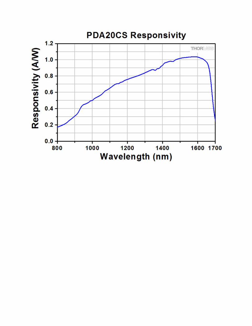
PDA05CF2b 800 - 1700 nm DC - 150 MHz 2.3 ns 1.04 A/W @ 1590 nm 12.6 pW/Hz1/2 0.2 mm2 (Ø0.5 mm) 10 to 50 °C
PDF10C 800 - 1700 nm DC - 25 Hz 19 ms 1.0 A/W @ 1550 nm 7.5 x 10⁻³ pW/Hz1/2 0.2 mm2 (Ø0.5 mm) 18 to 28 °C
PDA20C 800 - 1700 nm DC - 5 MHz 70 ns 1 A/W @ 1550 nm 22 pW/Hz1/2 3.14 mm2 (Ø2.0 mm) 10 to 50 °C
PDA10D 800 - 2600 nm DC - 15 MHz 23.3 ns 1.35 A/W @ 2300 nm 35 pW/Hz1/2 0.8 mm2 (Ø1.0 mm) 10 to 50 °C
FPD510-F 850 - 1650 nm DC - 250 MHz 2 ns - 3.2 pW/Hz1/2 0.13 mm2 (Ø0.4 mm) 10 to 40 °C
FPD610-FS-NIR 950 - 1650 nm DC - 600 MHz 1 ns - 6.6 pW/Hz1/2 5 x 10⁻³ mm2 (Ø0.08 mm) 10 to 40 °C
Switchable Gain
PDA20CS 800 - 1700 nm DC - 10 MHzc N/Ad 1.04 A/W @ 1590 1.14 - 51.2 pW/Hz1/2 3.14 mm2 (Ø2.0 mm) 0 to 70 °C
PDA10CS 900 - 1700 nm DC - 17 MHzc N/Ad 1.05 A/W @ 1550 nm 1.25 - 60 pW/Hz1/2 0.8 mm2 (Ø1.0 mm) 0 to 40 °C
FPD310-FS-NIR 950 - 1650 nm 1 - 1500 MHz 0.5 ns - 14.1 pW/Hz1/2 5 x 10⁻³ mm2 (Ø0.08 mm) 10 to 40 °C
NEP is specified at the peak responsivity wavelength. As NEP changes with the gain setting for the switchable-gain versions, an NEP range is givenfor these.
b. This detector has a 50 Ω terminator resistor that is in series with the amplifier output. This forms a voltage divider with any load impedance (e.g. 50 Ωload divides signal in half)his is the maximum possible bandwidth for these amplified photodetectors. Bandwidth varies as a function of gain. For more information see the
Switchable Gain table below.
S P E C S & N B S P ;
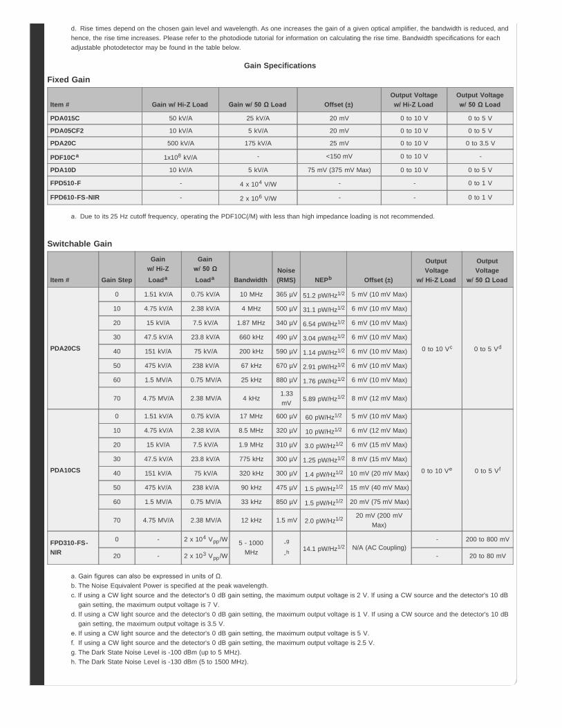
Rise times depend on the chosen gain level and wavelength. As one increases the gain of a given optical amplifier, the bandwidth is reduced, andhence, the rise time increases. Please refer to the photodiode tutorial for information on calculating the rise time. Bandwidth specifications for eachadjustable photodetector may be found in the table below.
Gain Specifications
Fixed Gain
Item # Gain w/ Hi-Z Load Gain w/ 50 Ω Load Offset (±)Output Voltagew/ Hi-Z Load
Output Voltagew/ 50 Ω Load
PDA015C 50 kV/A 25 kV/A 20 mV 0 to 10 V 0 to 5 V
PDA05CF2 10 kV/A 5 kV/A 20 mV 0 to 10 V 0 to 5 V
PDA20C 500 kV/A 175 kV/A 25 mV 0 to 10 V 0 to 3.5 V
PDF10Ca 1x10⁸ kV/A - <150 mV 0 to 10 V -
PDA10D 10 kV/A 5 kV/A 75 mV (375 mV Max) 0 to 10 V 0 to 5 V
FPD510-F - 4 x 10⁴ V/W - - 0 to 1 V
FPD610-FS-NIR - 2 x 10⁶ V/W - - 0 to 1 V
Due to its 25 Hz cutoff frequency, operating the PDF10C(/M) with less than high impedance loading is not recommended.
Switchable Gain
Item # Gain Step
Gainw/ Hi-ZLoada
Gainw/ 50 ΩLoada Bandwidth
Noise(RMS) NEPb Offset (±)
OutputVoltage
w/ Hi-Z Load
OutputVoltage
w/ 50 Ω Load
PDA20CS
0 1.51 kV/A 0.75 kV/A 10 MHz 365 µV 51.2 pW/Hz1/2 5 mV (10 mV Max)
0 to 10 Vc 0 to 5 Vd
10 4.75 kV/A 2.38 kV/A 4 MHz 500 µV 31.1 pW/Hz1/2 6 mV (10 mV Max)
20 15 kV/A 7.5 kV/A 1.87 MHz 340 µV 6.54 pW/Hz1/2 6 mV (10 mV Max)
30 47.5 kV/A 23.8 kV/A 660 kHz 490 µV 3.04 pW/Hz1/2 6 mV (10 mV Max)
40 151 kV/A 75 kV/A 200 kHz 590 µV 1.14 pW/Hz1/2 6 mV (10 mV Max)
50 475 kV/A 238 kV/A 67 kHz 670 µV 2.91 pW/Hz1/2 6 mV (10 mV Max)
60 1.5 MV/A 0.75 MV/A 25 kHz 880 µV 1.76 pW/Hz1/2 6 mV (10 mV Max)
70 4.75 MV/A 2.38 MV/A 4 kHz1.33mV 5.89 pW/Hz1/2 8 mV (12 mV Max)
PDA10CS
0 1.51 kV/A 0.75 kV/A 17 MHz 600 µV 60 pW/Hz1/2 5 mV (10 mV Max)
0 to 10 Ve 0 to 5 Vf
10 4.75 kV/A 2.38 kV/A 8.5 MHz 320 µV 10 pW/Hz1/2 6 mV (12 mV Max)
20 15 kV/A 7.5 kV/A 1.9 MHz 310 µV 3.0 pW/Hz1/2 6 mV (15 mV Max)
30 47.5 kV/A 23.8 kV/A 775 kHz 300 µV 1.25 pW/Hz1/2 8 mV (15 mV Max)
40 151 kV/A 75 kV/A 320 kHz 300 µV 1.4 pW/Hz1/2 10 mV (20 mV Max)
50 475 kV/A 238 kV/A 90 kHz 475 µV 1.5 pW/Hz1/2 15 mV (40 mV Max)
60 1.5 MV/A 0.75 MV/A 33 kHz 850 µV 1.5 pW/Hz1/2 20 mV (75 mV Max)
70 4.75 MV/A 2.38 MV/A 12 kHz 1.5 mV 2.0 pW/Hz1/2 20 mV (200 mVMax)
FPD310-FS-NIR
0 - 2 x 10⁴ Vpp/W 5 - 1000MHz
-g
-h 14.1 pW/Hz1/2 N/A (AC Coupling)- 200 to 800 mV
20 - 2 x 10³ Vpp/W - 20 to 80 mV
a. Gain figures can also be expressed in units of Ω.The Noise Equivalent Power is specified at the peak wavelength.If using a CW light source and the detector's 0 dB gain setting, the maximum output voltage is 2 V. If using a CW source and the detector's 10 dBgain setting, the maximum output voltage is 7 V.If using a CW light source and the detector's 0 dB gain setting, the maximum output voltage is 1 V. If using a CW source and the detector's 10 dBgain setting, the maximum output voltage is 3.5 V.If using a CW light source and the detector's 0 dB gain setting, the maximum output voltage is 5 V.If using a CW light source and the detector's 0 dB gain setting, the maximum output voltage is 2.5 V.The Dark State Noise Level is -100 dBm (up to 5 MHz).The Dark State Noise Level is -130 dBm (5 to 1500 MHz).
Hide Housing Features
Hide Mounting Options
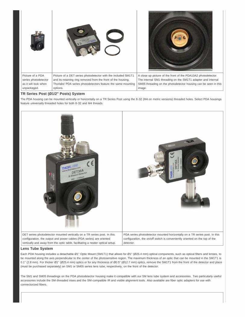
Click to EnlargeTop of the housing on our
PDA and PDF detectorhousings. The Power Inconnector, Output BNCconnector, and power
indicator LED are located atthe top of the housing. ThePDA015C detector is shown.
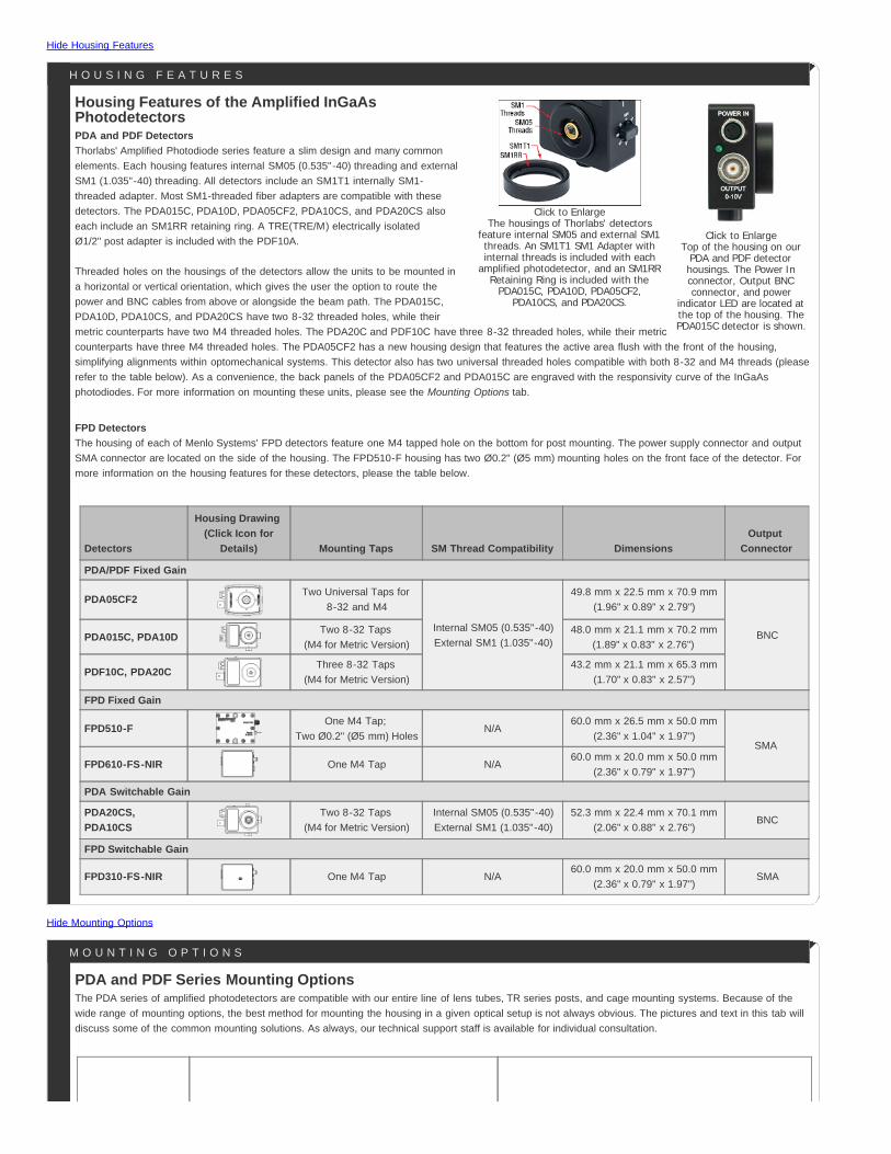
Click to EnlargeThe housings of Thorlabs' detectors
feature internal SM05 and external SM1threads. An SM1T1 SM1 Adapter withinternal threads is included with each
amplified photodetector, and an SM1RRRetaining Ring is included with the
PDA015C, PDA10D, PDA05CF2,PDA10CS, and PDA20CS.
Detectors
Housing Drawing (Click Icon for
Details) Mounting Taps SM Thread Compatibility DimensionsOutput
Connector
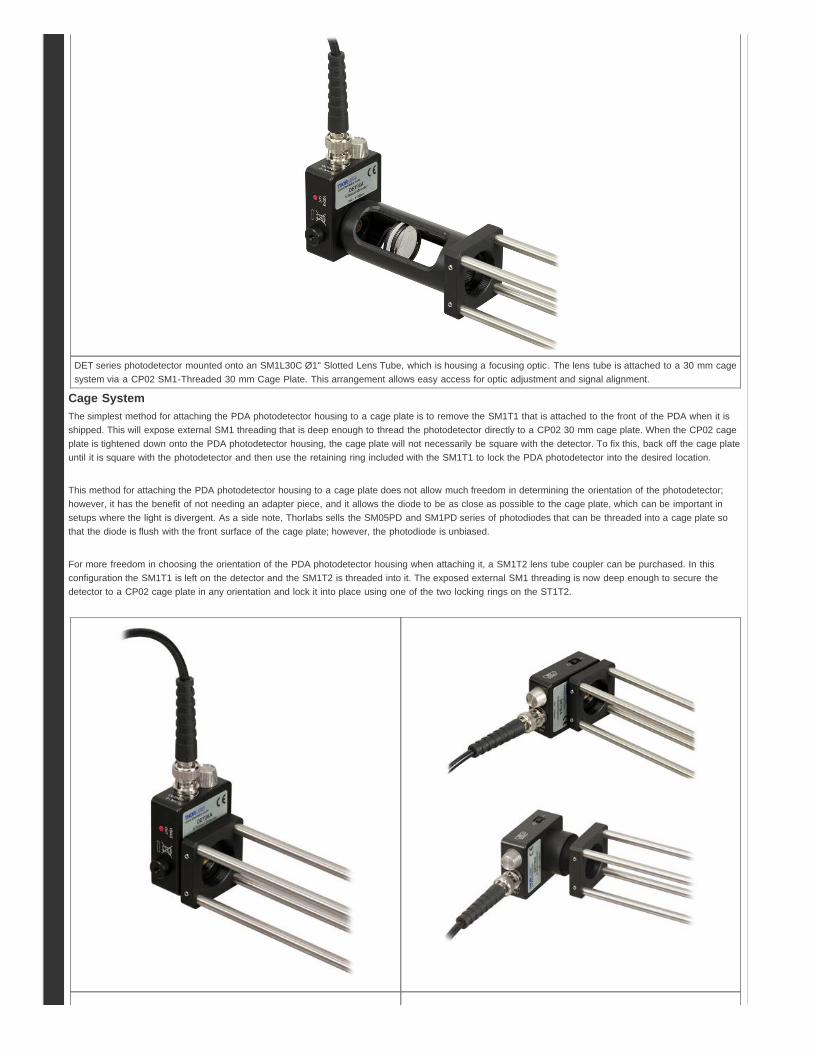
PDA/PDF Fixed Gain
PDA05CF2Two Universal Taps for
8-32 and M4
Internal SM05 (0.535"-40)External SM1 (1.035"-40)
49.8 mm x 22.5 mm x 70.9 mm(1.96" x 0.89" x 2.79")
BNCPDA015C, PDA10DTwo 8-32 Taps
(M4 for Metric Version)48.0 mm x 21.1 mm x 70.2 mm
(1.89" x 0.83" x 2.76")
PDF10C, PDA20CThree 8-32 Taps
(M4 for Metric Version)43.2 mm x 21.1 mm x 65.3 mm
(1.70" x 0.83" x 2.57")
FPD Fixed Gain
FPD510-FOne M4 Tap;
Two Ø0.2" (Ø5 mm) HolesN/A
60.0 mm x 26.5 mm x 50.0 mm(2.36" x 1.04" x 1.97")
SMA
FPD610-FS-NIR One M4 Tap N/A60.0 mm x 20.0 mm x 50.0 mm
(2.36" x 0.79" x 1.97")
PDA Switchable Gain
PDA20CS,PDA10CS
Two 8-32 Taps (M4 for Metric Version)
Internal SM05 (0.535"-40)External SM1 (1.035"-40)
52.3 mm x 22.4 mm x 70.1 mm(2.06" x 0.88" x 2.76")
BNC
FPD Switchable Gain
FPD310-FS-NIR One M4 Tap N/A60.0 mm x 20.0 mm x 50.0 mm
(2.36" x 0.79" x 1.97")SMA
Housing Features of the Amplified InGaAsPhotodetectorsPDA and PDF DetectorsThorlabs' Amplified Photodiode series feature a slim design and many commonelements. Each housing features internal SM05 (0.535"-40) threading and externalSM1 (1.035"-40) threading. All detectors include an SM1T1 internally SM1-threaded adapter. Most SM1-threaded fiber adapters are compatible with thesedetectors. The PDA015C, PDA10D, PDA05CF2, PDA10CS, and PDA20CS alsoeach include an SM1RR retaining ring. A TRE(TRE/M) electrically isolatedØ1/2" post adapter is included with the PDF10A.
Threaded holes on the housings of the detectors allow the units to be mounted ina horizontal or vertical orientation, which gives the user the option to route thepower and BNC cables from above or alongside the beam path. The PDA015C,PDA10D, PDA10CS, and PDA20CS have two 8-32 threaded holes, while theirmetric counterparts have two M4 threaded holes. The PDA20C and PDF10C have three 8-32 threaded holes, while their metriccounterparts have three M4 threaded holes. The PDA05CF2 has a new housing design that features the active area flush with the front of the housing,simplifying alignments within optomechanical systems. This detector also has two universal threaded holes compatible with both 8-32 and M4 threads (pleaserefer to the table below). As a convenience, the back panels of the PDA05CF2 and PDA015C are engraved with the responsivity curve of the InGaAsphotodiodes. For more information on mounting these units, please see the Mounting Options tab.
FPD DetectorsThe housing of each of Menlo Systems' FPD detectors feature one M4 tapped hole on the bottom for post mounting. The power supply connector and outputSMA connector are located on the side of the housing. The FPD510-F housing has two Ø0.2" (Ø5 mm) mounting holes on the front face of the detector. Formore information on the housing features for these detectors, please the table below.
H O U S I N G F E A T U R E S
PDA and PDF Series Mounting OptionsThe PDA series of amplified photodetectors are compatible with our entire line of lens tubes, TR series posts, and cage mounting systems. Because of thewide range of mounting options, the best method for mounting the housing in a given optical setup is not always obvious. The pictures and text in this tab willdiscuss some of the common mounting solutions. As always, our technical support staff is available for individual consultation.
M O U N T I N G O P T I O N S
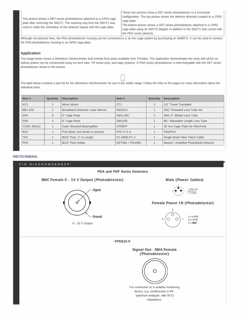
Picture of a PDAseries photodetectoras it will look whenunpackaged.
Picture of a DET series photodetector with the included SM1T1and its retaining ring removed from the front of the housing.Thorlabs' PDA series photodetectors feature the same mountingoptions.
A close up picture of the front of the PDA10A2 photodetector.The internal SM1 threading on the SM1T1 adapter and internalSM05 threading on the photodetector housing can be seen in thisimage.
TR Series Post (Ø1/2" Posts) SystemThe PDA housing can be mounted vertically or horizontally on a TR Series Post using the 8-32 (M4 on metric versions) threaded holes. Select PDA housingsfeature universally threaded holes for both 8-32 and M4 threads.
DET series photodetector mounted vertically on a TR series post. In thisconfiguration, the output and power cables (PDA series) are orientedvertically and away from the optic table, facilitating a neater optical setup.
PDA series photodetector mounted horizontally on a TR series post. In thisconfiguration, the on/off switch is conveniently oriented on the top of thedetector.
Lens Tube SystemEach PDA housing includes a detachable Ø1" Optic Mount (SM1T1) that allows for Ø1" (Ø25.4 mm) optical components, such as optical filters and lenses, tobe mounted along the axis perpendicular to the center of the photosensitive region. The maximum thickness of an optic that can be mounted in the SM1T1 is0.1" (2.8 mm). For thicker Ø1" (Ø25.4 mm) optics or for any thickness of Ø0.5" (Ø12.7 mm) optics, remove the SM1T1 from the front of the detector and place(must be purchased separately) an SM1 or SM05 series lens tube, respectively, on the front of the detector.
The SM1 and SM05 threadings on the PDA photodetector housing make it compatible with our SM lens tube system and accessories. Two particularly usefulaccessories include the SM-threaded irises and the SM-compatible IR and visible alignment tools. Also available are fiber optic adapters for use withconnectorized fibers.
DET series photodetector mounted onto an SM1L30C Ø1" Slotted Lens Tube, which is housing a focusing optic. The lens tube is attached to a 30 mm cagesystem via a CP02 SM1-Threaded 30 mm Cage Plate. This arrangement allows easy access for optic adjustment and signal alignment.
Cage SystemThe simplest method for attaching the PDA photodetector housing to a cage plate is to remove the SM1T1 that is attached to the front of the PDA when it isshipped. This will expose external SM1 threading that is deep enough to thread the photodetector directly to a CP02 30 mm cage plate. When the CP02 cageplate is tightened down onto the PDA photodetector housing, the cage plate will not necessarily be square with the detector. To fix this, back off the cage plateuntil it is square with the photodetector and then use the retaining ring included with the SM1T1 to lock the PDA photodetector into the desired location.
This method for attaching the PDA photodetector housing to a cage plate does not allow much freedom in determining the orientation of the photodetector;however, it has the benefit of not needing an adapter piece, and it allows the diode to be as close as possible to the cage plate, which can be important insetups where the light is divergent. As a side note, Thorlabs sells the SM05PD and SM1PD series of photodiodes that can be threaded into a cage plate sothat the diode is flush with the front surface of the cage plate; however, the photodiode is unbiased.
For more freedom in choosing the orientation of the PDA photodetector housing when attaching it, a SM1T2 lens tube coupler can be purchased. In thisconfiguration the SM1T1 is left on the detector and the SM1T2 is threaded into it. The exposed external SM1 threading is now deep enough to secure thedetector to a CP02 cage plate in any orientation and lock it into place using one of the two locking rings on the ST1T2.
Hide Pin Diagrams
This picture shows a DET series photodetector attached to a CP02 cageplate after removing the SM1T1. The retaining ring from the SM1T1 wasused to make the orientation of the detector square with the cage plate.
These two pictures show a DET series photodetector in a horizontalconfiguration. The top picture shows the detector directely coupled to a CP02cage plate.The bottom picture shows a DET series photodetector attached to a CP02cage plate using an SM1T2 adapter in addition to the SM1T1 that comes withthe PDA series detector.
Although not pictured here, the PDA photodetector housing can be connected to a 16 mm cage system by purchasing an SM05T2. It can be used to connectthe PDA photodetector housing to an SP02 cage plate.
ApplicationThe image below shows a Michelson Interferometer built entirely from parts available from Thorlabs. This application demonstrates the ease with which anoptical system can be constructed using our lens tube, TR series post, and cage systems. A PDA series photodetector is interchangable with the DET seriesphotodetector shown in the picture.
The table below contains a part list for the Michelson Interferometer for use in the visible range. Follow the links to the pages for more information about theindividual parts.
Item # Quantity Description Item # Quantity Description
KC1 1 Mirror Mount CT1 1 1/2" Travel Translator
BB1-E02 2 Broadband Dielectric Laser Mirrors SM1D12 1 SM1 Threaded Lens Tube Iris
ER4 8 4" Cage Rods SM1L30C 1 SM1 3" Slotted Lens Tube
ER6 4 6" Cage Rods SM1V05 1 Ø1" Adjustable Length Lens Tube
CCM1-BS013 1 Cube-Mounted Beamsplitter CP08FP 1 30 mm Cage Plate for FiberPorts
BA2 1 Post Base (not shown in picture) PAF-X-5-A 1 FiberPort
TR2 1 Ø1/2" Post, 2" in Length P1-460B-FC-2 1 Single Mode Fiber Patch Cable
PH2 1 Ø1/2" Post Holder DET36A / PDA36A 1 Biased / Amplified Photodiode Detector
BNC Female 0 - 10 V Output (Photodetector)
0 - 10 V Output
Male (Power Cables)
Female Power IN (Photodetector)
Signal Out- SMA Female(Photodetector)
For connection to a suitable monitoringdevice, e.g. oscilloscope or RF-spectrum-analyzer, with 50 Ω
impedance.
PDA and PDF Series Detectors
FPD510-F
P I N D I A G R A M S & N B S P ;

Hide Photodiode Tutorial
Signal Out- SMA Female(Photodetector)
For connection to a suitable monitoringdevice, e.g. oscilloscope or RF-spectrum-analyzer, with 50 Ω
impedance.
Female (Power Cables)
Male Power IN (Photodetector)
FPD310-FS-NIR and FPD610-FS-NIR
Photodiode TutorialTheory of OperationA junction photodiode is an intrinsic device that behaves similarly to an ordinary signal diode, but it generates a photocurrent when light is absorbed in thedepleted region of the junction semiconductor. A photodiode is a fast, highly linear device that exhibits high quantum efficiency based upon the application andmay be used in a variety of different applications.
It is necessary to be able to correctly determine the level of the output current to expect and the responsivity based upon the incident light. Depicted in Figure1 is a junction photodiode model with basic discrete components to help visualize the main characteristics and gain a better understanding of the operation ofThorlabs' photodiodes.
Figure 1: Photodiode Model
Photodiode TerminologyResponsivityThe responsivity of a photodiode can be defined as a ratio of generated photocurrent (IPD) to the incident light power (P) at a given wavelength:
Modes of Operation (Photoconductive vs. Photovoltaic)A photodiode can be operated in one of two modes: photoconductive (reverse bias) or photovoltaic (zero-bias). Mode selection depends upon the application's
P H O T O D I O D E T U T O R I A L
speed requirements and the amount of tolerable dark current (leakage current).
PhotoconductiveIn photoconductive mode, an external reverse bias is applied, which is the basis for our DET series detectors. The current measured through the circuitindicates illumination of the device; the measured output current is linearly proportional to the input optical power. Applying a reverse bias increases the widthof the depletion junction producing an increased responsivity with a decrease in junction capacitance and produces a very linear response. Operating underthese conditions does tend to produce a larger dark current, but this can be limited based upon the photodiode material. (Note: Our DET detectors are reversebiased and cannot be operated under a forward bias.)
PhotovoltaicIn photovoltaic mode the photodiode is zero biased. The flow of current out of the device is restricted and a voltage builds up. This mode of operation exploitsthe photovoltaic effect, which is the basis for solar cells. The amount of dark current is kept at a minimum when operating in photovoltaic mode.
Dark CurrentDark current is leakage current that flows when a bias voltage is applied to a photodiode. When operating in a photoconductive mode, there tends to be ahigher dark current that varies directly with temperature. Dark current approximately doubles for every 10 °C increase in temperature, and shunt resistancetends to double for every 6 °C rise. Of course, applying a higher bias will decrease the junction capacitance but will increase the amount of dark currentpresent.
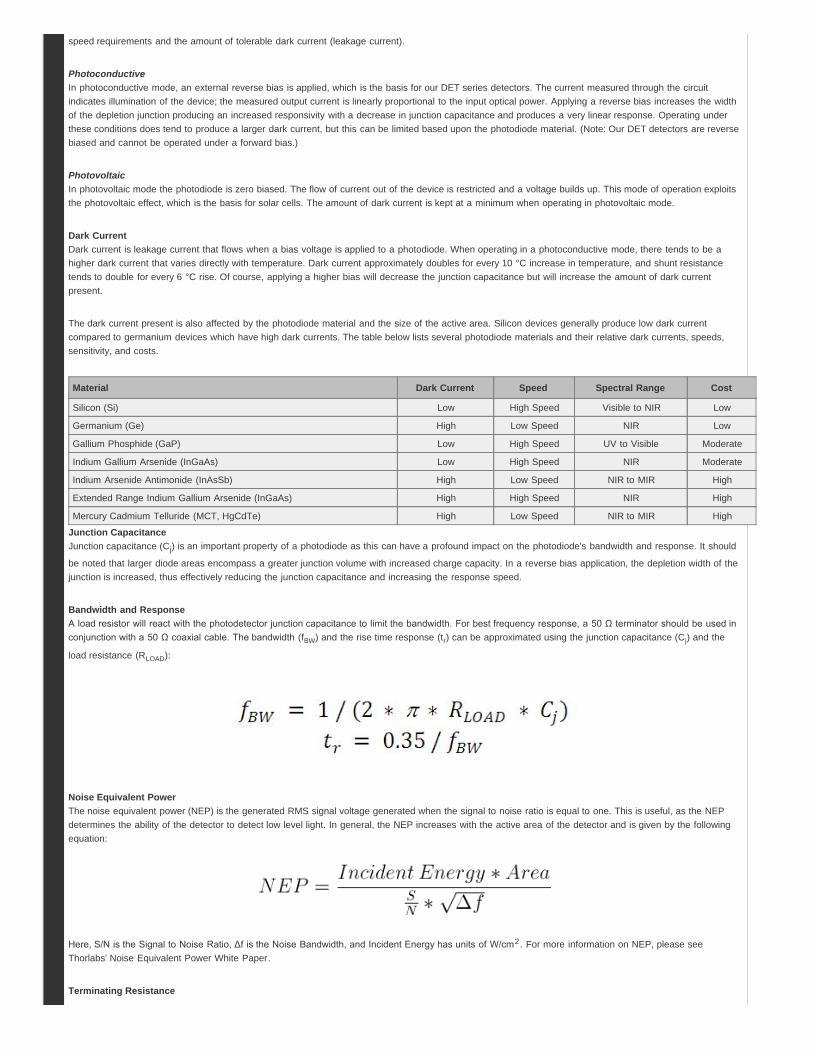
The dark current present is also affected by the photodiode material and the size of the active area. Silicon devices generally produce low dark currentcompared to germanium devices which have high dark currents. The table below lists several photodiode materials and their relative dark currents, speeds,sensitivity, and costs.
Material Dark Current Speed Spectral Range Cost
Silicon (Si) Low High Speed Visible to NIR Low
Germanium (Ge) High Low Speed NIR Low
Gallium Phosphide (GaP) Low High Speed UV to Visible Moderate
Indium Gallium Arsenide (InGaAs) Low High Speed NIR Moderate
Indium Arsenide Antimonide (InAsSb) High Low Speed NIR to MIR High
Extended Range Indium Gallium Arsenide (InGaAs) High High Speed NIR High
Mercury Cadmium Telluride (MCT, HgCdTe) High Low Speed NIR to MIR High
Junction CapacitanceJunction capacitance (Cj) is an important property of a photodiode as this can have a profound impact on the photodiode's bandwidth and response. It should
be noted that larger diode areas encompass a greater junction volume with increased charge capacity. In a reverse bias application, the depletion width of thejunction is increased, thus effectively reducing the junction capacitance and increasing the response speed.
Bandwidth and ResponseA load resistor will react with the photodetector junction capacitance to limit the bandwidth. For best frequency response, a 50 Ω terminator should be used inconjunction with a 50 Ω coaxial cable. The bandwidth (fBW) and the rise time response (tr) can be approximated using the junction capacitance (Cj) and the
load resistance (RLOAD):
Noise Equivalent PowerThe noise equivalent power (NEP) is the generated RMS signal voltage generated when the signal to noise ratio is equal to one. This is useful, as the NEPdetermines the ability of the detector to detect low level light. In general, the NEP increases with the active area of the detector and is given by the followingequation:
Here, S/N is the Signal to Noise Ratio, Δf is the Noise Bandwidth, and Incident Energy has units of W/cm2. For more information on NEP, please seeThorlabs' Noise Equivalent Power White Paper.
Terminating Resistance
A load resistance is used to convert the generated photocurrent into a voltage (VOUT) for viewing on an oscilloscope:
Depending on the type of the photodiode, load resistance can affect the response speed. For maximum bandwidth, we recommend using a 50 Ω coaxial cablewith a 50 Ω terminating resistor at the opposite end of the cable. This will minimize ringing by matching the cable with its characteristic impedance. Ifbandwidth is not important, you may increase the amount of voltage for a given light level by increasing RLOAD. In an unmatched termination, the length of the
coaxial cable can have a profound impact on the response, so it is recommended to keep the cable as short as possible.
Shunt ResistanceShunt resistance represents the resistance of the zero-biased photodiode junction. An ideal photodiode will have an infinite shunt resistance, but actual valuesmay range from the order of ten Ω to thousands of MΩ and is dependent on the photodiode material. For example, and InGaAs detector has a shuntresistance on the order of 10 MΩ while a Ge detector is in the kΩ range. This can significantly impact the noise current on the photodiode. For mostapplications, however, the high resistance produces little effect and can be ignored.
Series ResistanceSeries resistance is the resistance of the semiconductor material, and this low resistance can generally be ignored. The series resistance arises from thecontacts and the wire bonds of the photodiode and is used to mainly determine the linearity of the photodiode under zero bias conditions.
Common Operating Circuits
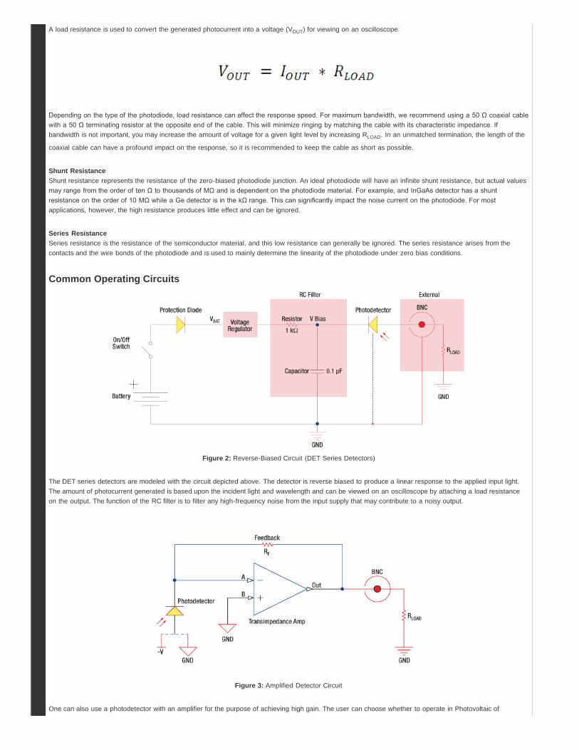
Figure 2: Reverse-Biased Circuit (DET Series Detectors)
The DET series detectors are modeled with the circuit depicted above. The detector is reverse biased to produce a linear response to the applied input light.The amount of photocurrent generated is based upon the incident light and wavelength and can be viewed on an oscilloscope by attaching a load resistanceon the output. The function of the RC filter is to filter any high-frequency noise from the input supply that may contribute to a noisy output.
Figure 3: Amplified Detector Circuit
One can also use a photodetector with an amplifier for the purpose of achieving high gain. The user can choose whether to operate in Photovoltaic of
Hide Cross Reference
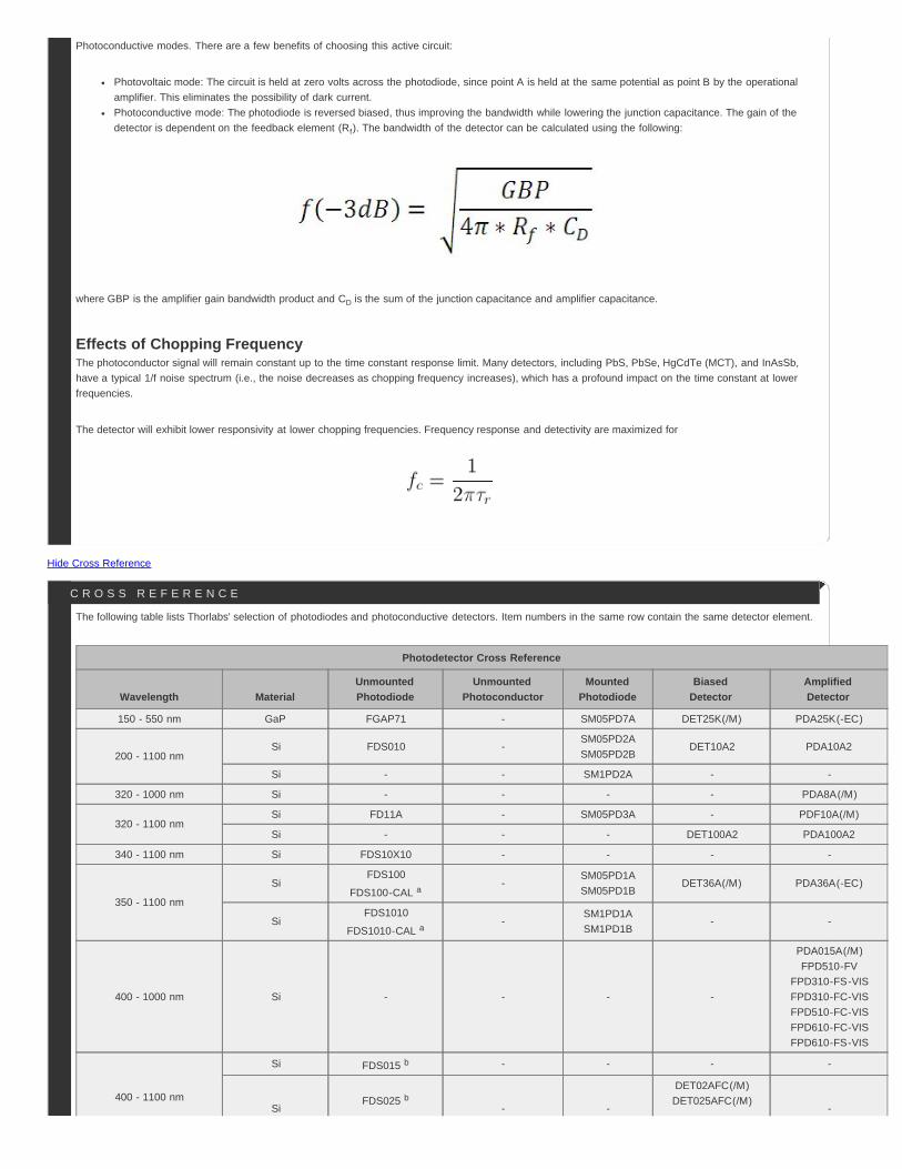
Photoconductive modes. There are a few benefits of choosing this active circuit:
Photovoltaic mode: The circuit is held at zero volts across the photodiode, since point A is held at the same potential as point B by the operationalamplifier. This eliminates the possibility of dark current.Photoconductive mode: The photodiode is reversed biased, thus improving the bandwidth while lowering the junction capacitance. The gain of thedetector is dependent on the feedback element (Rf). The bandwidth of the detector can be calculated using the following:
where GBP is the amplifier gain bandwidth product and CD is the sum of the junction capacitance and amplifier capacitance.
Effects of Chopping FrequencyThe photoconductor signal will remain constant up to the time constant response limit. Many detectors, including PbS, PbSe, HgCdTe (MCT), and InAsSb,have a typical 1/f noise spectrum (i.e., the noise decreases as chopping frequency increases), which has a profound impact on the time constant at lowerfrequencies.
The detector will exhibit lower responsivity at lower chopping frequencies. Frequency response and detectivity are maximized for
The following table lists Thorlabs' selection of photodiodes and photoconductive detectors. Item numbers in the same row contain the same detector element.
Photodetector Cross Reference
Wavelength MaterialUnmountedPhotodiode
UnmountedPhotoconductor
MountedPhotodiode
BiasedDetector
AmplifiedDetector
150 - 550 nm GaP FGAP71 - SM05PD7A DET25K(/M) PDA25K(-EC)
200 - 1100 nmSi FDS010 -
SM05PD2ASM05PD2B
DET10A2 PDA10A2
Si - - SM1PD2A - -
320 - 1000 nm Si - - - - PDA8A(/M)
320 - 1100 nmSi FD11A - SM05PD3A - PDF10A(/M)
Si - - - DET100A2 PDA100A2
340 - 1100 nm Si FDS10X10 - - - -
350 - 1100 nm
SiFDS100
FDS100-CAL a-
SM05PD1ASM05PD1B
DET36A(/M) PDA36A(-EC)
SiFDS1010
FDS1010-CAL a-
SM1PD1ASM1PD1B
- -
400 - 1000 nm Si - - - -
PDA015A(/M)FPD510-FV
FPD310-FS-VISFPD310-FC-VISFPD510-FC-VISFPD610-FC-VISFPD610-FS-VIS
400 - 1100 nm
Si FDS015 b - - - -
SiFDS025 b
- -
DET02AFC(/M)DET025AFC(/M)
-
C R O S S R E F E R E N C E
Item #aHousing
FeaturesbWavelength
RangeBandwidth
RangeRiseTime
Gain
NEP
TypicalPerformance
GraphsActiveAreac
OperatingTemperature
Range
PowerSupply
IncludedHi-Z Load
50 ΩLoad
PDA015C800 -
1700 nmDC -
380 MHz1.0 ns 50 kV/A 25 kV/A 20 pW/Hz1/2 0.018 mm2
(Ø150 µm)10 to 40 °C Yes
PDA05CF2800 - 1700
nmDC - 150
MHz2.3 ns 10 kV/A 5 kV/A 12.6 pW/Hz1/2
0.2 mm2
(Ø0.5
mm)d10 to 50 °C Yes
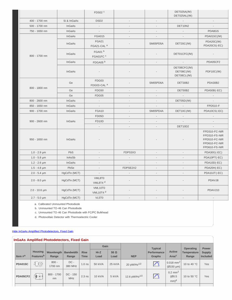
Hide InGaAs Amplified Photodetectors, Fixed Gain
InGaAs Amplified Photodetectors, Fixed Gain
FDS02 c DET025A(/M)DET025AL(/M)
400 - 1700 nm Si & InGaAs DSD2 - - - -
500 - 1700 nm InGaAs - - - DET10N2 -
750 - 1650 nm InGaAs - - - - PDA8GS
800 - 1700 nm
InGaAs FGA015 - - - PDA015C(/M)
InGaAsFGA21
FGA21-CAL a- SM05PD5A DET20C(/M)
PDA20C(/M)PDA20CS(-EC)
InGaAsFGA01 b
FGA01FC c- - DET01CFC(/M) -
InGaAs FDGA05 b - - - PDA05CF2
InGaAs - - -DET08CFC(/M)
DET08C(/M)DET08CL(/M)
PDF10C(/M)
800 - 1800 nm
GeFDG03
FDG03-CAL a- SM05PD6A DET30B2 PDA30B2
Ge FDG50 - - DET50B2 PDA50B(-EC)
Ge FDG05 - - - -
800 - 2600 nm InGaAs - - - DET05D(/M) -
850 - 1650 nm InGaAs - - - - FPD510-F
900 - 1700 nm InGaAs FGA10 - SM05PD4A DET10C(/M) PDA10CS(-EC)
900 - 2600 nm InGaAs
FD05D - - - -
FD10D - - - -
- - - DET10D2 -
950 - 1650 nm InGaAs - - - -
FPD310-FC-NIRFPD310-FS-NIRFPD510-FC-NIRFPD610-FC-NIRFPD610-FS-NIR
1.0 - 2.9 µm PbS - FDPS3X3 - - PDA30G(-EC)
1.0 - 5.8 µm InAsSb - - - - PDA10PT(-EC)
1.2 - 2.6 µm InGaAs - - - - PDA10D(-EC)
1.5 - 4.8 µm PbSe - FDPSE2X2 - - PDA20H(-EC)
2.0 - 5.4 µm HgCdTe (MCT) - - - - PDA10JT(-EC)
2.0 - 8.0 µm HgCdTe (MCT)VML8T0
VML8T4 d- - - PDAVJ8
2.0 - 10.6 µm HgCdTe (MCT)VML10T0
VML10T4 d- - - PDAVJ10
2.7 - 5.0 µm HgCdTe (MCT) VL5T0 - - - -
Calibrated Unmounted PhotodiodeUnmounted TO-46 Can PhotodiodeUnmounted TO-46 Can Photodiode with FC/PC Bulkhead
Photovoltaic Detector with Thermoelectric Cooler
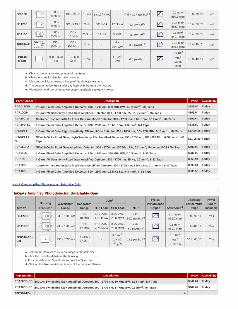
PDF10C800 -
1700 nmDC - 25 Hz 19 ms 1 x 10⁸ kV/A - 7.5 x 10⁻³ pW/Hz1/2 0.2 mm2
(Ø0.5 mm)18 to 28 °C Yes
PDA20C800 -
1700 nmDC - 5 MHz 70 ns 500 kV/A 175 kV/A 22 pW/Hz1/2 3.14 mm2
(Ø2.0 mm)10 to 50 °C Yes
PDA10D800 -
2600 nmDC -
15 MHz23.3 ns 10 kV/A 5 kV/A 35 pW/Hz1/2 0.8 mm2
(Ø1.0 mm)10 to 50 °C Yes
FPD510-F850 -
1650 nmDC -
250 MHz2 ns -
4 x
104 V/W3.2 pW/Hz1/2 0.13 mm2
(Ø0.4 mm)10 to 40 °C Noe
FPD610-FS-NIR
950 - 1650nm
DC - 600MHz
1 ns - 2 x 10⁶
V/W6.6 pW/Hz1/2
5 x 10⁻³
mm2
(Ø0.08mm)
10 to 40 °C Yes
Click on the links to view photos of the items.Click the icons for details of the housing.Click on the links to view an image of the detector element.The detector active area surface is flush with the front the housing. We recommend the LDS9 power supply, available separately below.
Item #aHousing
FeaturesbWavelength
RangeBandwidth
Range
Gainc
NEP
TypicalPerformance
Graphs ActiveAread
OperatingTemperature
Range
PowerSupply
IncludedHi-Z Load 50 Ω Load
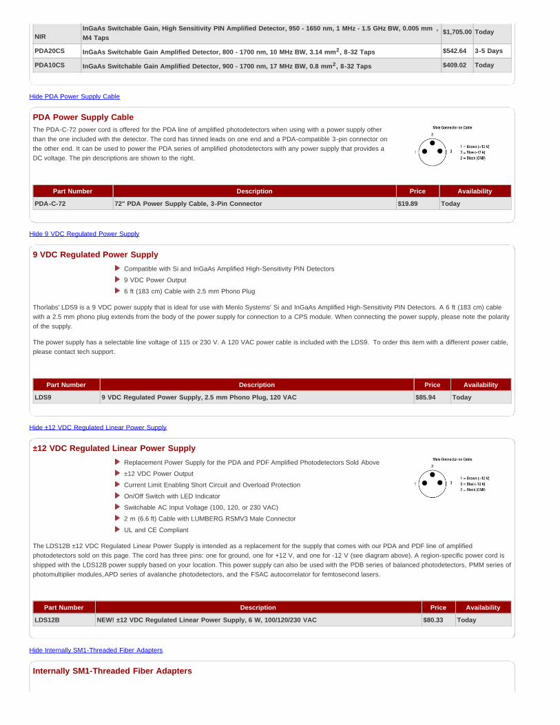
PDA20CS 800 - 1700 nmDC -
10 MHz1.51 kV/A -4.75 MV/A
0.75 kVA -2.38 MV/A
1.14 -
51.2 pW/Hz1/23.14 mm2
(Ø2.0 mm)0 to 70 °C Yes
PDA10CS 900 - 1700 nmDC -
17 MHz1.51 kV/A -4.75 MV/A
0.75 kVA -2.38 MV/A
1.25 -
60 pW/Hz1/20.8 mm2
(Ø1.0 mm)0 to 40 °C Yes
FPD310-FS-NIR
950 - 1650 nm 1 MHz -1.5 GHz
-2 x 10³ -
2 x 10⁴
Vpp/W14.1 pW/Hz1/2
5 x 10⁻³
mm2
(Ø0.08 mm)
10 to 40 °C Yes
ick on the Item #'s to view an image of the detector.Click the icons for details of the housing.For complete Gain Specifications, see the Specs tab.Click on the links to view an image of the detector element.
Part Number Description Price Availability
PDA015C/M InGaAs Fixed Gain Amplified Detector, 800 - 1700 nm, 380 MHz BW, 0.018 mm2, M4 Taps $985.00 Today
PDF10C/M InGaAs fW Sensitivity Fixed Gain Amplified Detector, 800 - 1700 nm, 25 Hz, 0.2 mm2, M4 Taps $863.94 Today
PDA20C/M Customer Inspired!InGaAs Fixed Gain Amplified Detector, 800 - 1700 nm, 5 MHz BW, 3.14 mm2, M4 Taps $593.64 Today
PDA10D-EC InGaAs Fixed Gain Amplified Detector, 800 - 2600 nm, 15 MHz BW, 0.8 mm2, M4 Taps $535.50 Today
FPD510-F InGaAs Fixed Gain, High-Sensitivity PIN Amplified Detector, 850 - 1650 nm, DC - 200 MHz, 0.13 mm2, M4 Taps $1,426.98 Today
FPD610-FS-NIR
NEW! InGaAs Fixed Gain, High-Sensitivity PIN Amplified Detector, 950 - 1650 nm, DC - 600 MHz, 0.005 mm2, M4Taps
$1,705.00 Today
PDA05CF2 NEW! InGaAs Fixed Gain Amplified Detector, 800 - 1700 nm, 150 MHz BW, 0.2 mm2, Universal 8-32 / M4 Tap $409.02 Today
PDA015C InGaAs Fixed Gain Amplified Detector, 800 - 1700 nm, 380 MHz BW, 0.018 mm2, 8-32 Taps $985.00 Today
PDF10C InGaAs fW Sensitivity Fixed Gain Amplified Detector, 800 - 1700 nm, 25 Hz, 0.2 mm2, 8-32 Taps $863.94 Today
PDA20C Customer Inspired!InGaAs Fixed Gain Amplified Detector, 800 - 1700 nm, 5 MHz BW, 3.14 mm2, 8-32 Taps $593.64 Today
PDA10D InGaAs Fixed Gain Amplified Detector, 800 - 2600 nm, 15 MHz BW, 0.8 mm2, 8-32 Taps $535.50 Today
Hide InGaAs Amplified Photodetector, Switchable Gain
InGaAs Amplified Photodetector, Switchable Gain
Part Number Description Price Availability
PDA20CS-EC InGaAs Switchable Gain Amplified Detector, 800 - 1700 nm, 10 MHz BW, 3.14 mm2, M4 Taps $542.64 Today
PDA10CS-EC InGaAs Switchable Gain Amplified Detector, 900 - 1700 nm, 17 MHz BW, 0.8 mm2, M4 Taps $409.02 Today
FPD310-FS- 2
NIRInGaAs Switchable Gain, High Sensitivity PIN Amplified Detector, 950 - 1650 nm, 1 MHz - 1.5 GHz BW, 0.005 mm ,M4 Taps
$1,705.00 Today
PDA20CS InGaAs Switchable Gain Amplified Detector, 800 - 1700 nm, 10 MHz BW, 3.14 mm2, 8-32 Taps $542.64 3-5 Days
PDA10CS InGaAs Switchable Gain Amplified Detector, 900 - 1700 nm, 17 MHz BW, 0.8 mm2, 8-32 Taps $409.02 Today
Hide PDA Power Supply Cable
PDA Power Supply CableThe PDA-C-72 power cord is offered for the PDA line of amplified photodetectors when using with a power supply otherthan the one included with the detector. The cord has tinned leads on one end and a PDA-compatible 3-pin connector onthe other end. It can be used to power the PDA series of amplified photodetectors with any power supply that provides aDC voltage. The pin descriptions are shown to the right.
Part Number Description Price Availability
PDA-C-72 72" PDA Power Supply Cable, 3-Pin Connector $19.89 Today
Hide 9 VDC Regulated Power Supply
9 VDC Regulated Power SupplyCompatible with Si and InGaAs Amplified High-Sensitivity PIN Detectors
9 VDC Power Output
6 ft (183 cm) Cable with 2.5 mm Phono Plug
Thorlabs' LDS9 is a 9 VDC power supply that is ideal for use with Menlo Systems' Si and InGaAs Amplified High-Sensitivity PIN Detectors. A 6 ft (183 cm) cablewith a 2.5 mm phono plug extends from the body of the power supply for connection to a CPS module. When connecting the power supply, please note the polarityof the supply.
The power supply has a selectable line voltage of 115 or 230 V. A 120 VAC power cable is included with the LDS9. To order this item with a different power cable,please contact tech support.
Part Number Description Price Availability
LDS9 9 VDC Regulated Power Supply, 2.5 mm Phono Plug, 120 VAC $85.94 Today
Hide ±12 VDC Regulated Linear Power Supply
±12 VDC Regulated Linear Power SupplyReplacement Power Supply for the PDA and PDF Amplified Photodetectors Sold Above
±12 VDC Power Output
Current Limit Enabling Short Circuit and Overload Protection
On/Off Switch with LED Indicator
Switchable AC Input Voltage (100, 120, or 230 VAC)
2 m (6.6 ft) Cable with LUMBERG RSMV3 Male Connector
UL and CE Compliant
The LDS12B ±12 VDC Regulated Linear Power Supply is intended as a replacement for the supply that comes with our PDA and PDF line of amplifiedphotodetectors sold on this page. The cord has three pins: one for ground, one for +12 V, and one for -12 V (see diagram above). A region-specific power cord isshipped with the LDS12B power supply based on your location. This power supply can also be used with the PDB series of balanced photodetectors, PMM series ofphotomultiplier modules,APD series of avalanche photodetectors, and the FSAC autocorrelator for femtosecond lasers.
Part Number Description Price Availability
LDS12B NEW! ±12 VDC Regulated Linear Power Supply, 6 W, 100/120/230 VAC $80.33 Today
Hide Internally SM1-Threaded Fiber Adapters
Internally SM1-Threaded Fiber Adapters

Externally SM1-Threaded (1.035"-40) Disks with FC/PC, FC/APC, SMA, or ST/PCReceptacle
Light-Tight When Used with SM1 Lens Tubes
Compatible with Many of Our 30 mm Cage Plates and Photodetectors
These internally SM1-threaded (1.035"-40) adapters mate connectorized fiber to any of our externally SM1-threaded components, including our photodiode powersensors, our thermal power sensors, and our photodetectors. These adapters are compatible with the housing of the photodetectors on this page.
Item # S120-SMA S120-ST S120-SC S120-LC
Click Image to Enlarge
Fiber Connector Typea SMA ST SC LC
Thread Internal SM1 (1.035"-40)
Other Connector Types Available upon Request
Part Number Description Price Availability
S120-SMA SMA Fiber Adapter Cap with Internal SM1 (1.035"-40) Thread $39.78 Today
S120-ST ST/PC Fiber Adapter Cap with Internal SM1 (1.035"-40) Thread $39.78 Today
S120-SC SC/PC Fiber Adapter Cap with Internal SM1 (1.035"-40) Thread $49.98 Today
S120-LC LC/PC Fiber Adapter Cap with Internal SM1 (1.035"-40) Thread $49.98 Today
Hide Externally SM1-Threaded Fiber Adapters
Externally SM1-Threaded Fiber AdaptersEach disk has four dimples, two in the front surface and two in theback surface, that allow it to be tightened from either side with theSPW909 or SPW801 spanner wrench. The dimples do not go all theway through the disk so that the adapters can be used in light-tightapplications when paired with SM1 lens tubes. Once the adapter is atthe desired position, use an SM1RR retaining ring to secure it in place.
Item # SM1FC SM1FCAa SM1SMA SM1ST
Adapter Image(Click the Image to Enlarge)
Connector Type FC/PC FC/APC SMA ST/PC
Threading External SM1 (1.035"-40)
Please note that the SM1FCA has a mechanical angle of only 4°, even though the standard angle for these connectors is 8°. There is a 4° angle ofdeflection caused by the glass-air interface; when combined with the 4° mechanical angle, the output beam is aligned perpendicular to the adapter face.
Part Number Description Price Availability
SM1FC FC/PC Fiber Adapter Plate with External SM1 (1.035"-40) Thread $29.58 Today
SM1FCA FC/APC Fiber Adapter Plate with External SM1 (1.035"-40) Thread $31.37 Today
SM1SMA SMA Fiber Adapter Plate with External SM1 (1.035"-40) Thread $29.58 Today
SM1ST ST/PC Fiber Adapter Plate with External SM1 (1.035"-40) Thread $28.42 Today