| HAI LAMA MTANDAO - patentimages.storage.googleapis.com · ovaannyvvmmaaaanny...
22
| HAI LAMA MTANDAO WA WATU WANA NA WANA HAITI US009777543B2 ( 12 ) United States Patent ( 10 ) Patent No .: US 9, 777 , 543 B2 ( 45 ) Date of Patent : Oct . 3 , 2017 Ellis ( 54 ) DEVICE AND METHOD FOR MULTI - PATH FLOW FROM VERTICAL HYDRAULIC TANK B65D 88 / 54 ; Y10T 137 / 86196 ; Y10T 137 / 86308 ; Y10T 137 / 0318 ; Y10T 137 / 86035 ; Y10T 137 / 87877 See application file for complete search history . ( 71 ) Applicant : Vertical Tank , Inc . , Bakersfield , CA ( US ) ( 72 ) Inventor : Stan Ellis , Bakersfield , CA ( US ) ( 73 ) Assignee : Vertical Tank , Inc . , Bakersfield , CA ( US ) ( 56 ) References Cited U .S . PATENT DOCUMENTS 3, 849 , 197 A * 11 / 1974 Sorrentino . .. . . . . . . . . . C25D 21 /20 105 / 150 4, 901 , 563 A * 2/ 1990 Pearson . . . . . . . . . . . . B01F 15 / 00207 166 / 308 . 1 5, 964 , 304 A * 10 / 1999 Morrison , Jr . . . . . . . . .. . E21B 21 / 01 ( * ) Notice : Subject to any disclaimer , the term of this patent is extended or adjusted under 35 U . S .C . 154 ( b ) by 30 days . 175 / 206 ( 21 ) Appl . No .: 14 / 469 , 497 ( Continued ) Primary Examiner - Mary McManmon Assistant Examiner — Patrick Williams ( 74 ) Attorney , Agent , or Firm — Matthew C . McCarthy , Esq . ; Eastman & McCartney LLP ( 22 ) Filed : Aug . 26, 2014 ( 65 ) ( 65 ) Prior Publication Data US 2015 / 0059858 A1 Mar . 5 , 2015 ( 60 ) Related U .S . Application Data Provisional application No . 61 / 870 , 726 , filed on Aug . 27 , 2013 . ( 51 ) Int . CI . E21B 21 / 01 ( 2006 . 01 ) B65D 88 / 54 ( 2006 . 01 ) E21B 21 / 10 ( 2006 . 01 ) B65D 88 / 32 ( 2006 . 01 ) ( 52 ) U .S . CI . CPC .. .. . . .. . . .. .. E21B 21 / 01 ( 2013 . 01 ) ; B65D 88 / 32 ( 2013 . 01 ); B65D 88 / 54 ( 2013 . 01 ) ; E21B 21 / 106 ( 2013 . 01 ); Y1OT 137 / 0318 ( 2015 . 04 ); Y1OT 137 / 86035 ( 2015 . 04 ); Y1OT 137 / 86196 ( 2015 . 04 ); Y10T 137 / 86308 ( 2015 . 04 ) ( 58 ) Field of Classification Search CPC .. .. .. . E21B 21 / 01 ; E21B 21 / 106 ; B65D 88 / 32 ; ( 57 ) ABSTRACT A vertical hydraulic tank includes an upper cylindrical section and a lower conical section , with an outlet in the lower conical section . A lower multi - path manifold is attached to the outlet , the manifold including a vertical conduit in fluid communication with the outlet and a plu rality of horizontal conduits in fluid communication with the vertical conduit . An upper multi - path manifold can also be attached to the tank with a plurality of upper horizontal conduits and a vertical conduit in fluid communication with the upper cylindrical section of the tank . Valves may be provided along the vertical conduit and the horizontal con duits to regulate flow of material through the conduits . A pump may be connected to either the upper manifold or the lower manifold , or both by way of a pump conduit . Multiple tanks can be connected together by way of tubing between the manifolds of each tank . 14 Claims , 13 Drawing Sheets - 60 76 35 * 14 62 44 80 70 84 35 52 26 31 16 64 28 18 30 32
Transcript of | HAI LAMA MTANDAO - patentimages.storage.googleapis.com · ovaannyvvmmaaaanny...

| HAI LAMA MTANDAO WA WATU WANA NA WANA HAITI US009777543B2
( 12 ) United States Patent ( 10 ) Patent No . : US 9 , 777 , 543 B2 ( 45 ) Date of Patent : Oct . 3 , 2017 Ellis
( 54 ) DEVICE AND METHOD FOR MULTI - PATH FLOW FROM VERTICAL HYDRAULIC TANK
B65D 88 / 54 ; Y10T 137 / 86196 ; Y10T 137 / 86308 ; Y10T 137 / 0318 ; Y10T
137 / 86035 ; Y10T 137 / 87877 See application file for complete search history .
( 71 ) Applicant : Vertical Tank , Inc . , Bakersfield , CA ( US )
( 72 ) Inventor : Stan Ellis , Bakersfield , CA ( US )
( 73 ) Assignee : Vertical Tank , Inc . , Bakersfield , CA ( US )
( 56 ) References Cited
U . S . PATENT DOCUMENTS 3 , 849 , 197 A * 11 / 1974 Sorrentino . . . . . . . . . . . . C25D 21 / 20
105 / 150 4 , 901 , 563 A * 2 / 1990 Pearson . . . . . . . . . . . . B01F 15 / 00207
166 / 308 . 1 5 , 964 , 304 A * 10 / 1999 Morrison , Jr . . . . . . . . . . . E21B 21 / 01 ( * ) Notice : Subject to any disclaimer , the term of this
patent is extended or adjusted under 35 U . S . C . 154 ( b ) by 30 days .
175 / 206
( 21 ) Appl . No . : 14 / 469 , 497 ( Continued )
Primary Examiner - Mary McManmon Assistant Examiner — Patrick Williams ( 74 ) Attorney , Agent , or Firm — Matthew C . McCarthy , Esq . ; Eastman & McCartney LLP
( 22 ) Filed : Aug . 26 , 2014 ( 65 ) ( 65 ) Prior Publication Data
US 2015 / 0059858 A1 Mar . 5 , 2015
( 60 ) Related U . S . Application Data
Provisional application No . 61 / 870 , 726 , filed on Aug . 27 , 2013 .
( 51 ) Int . CI . E21B 21 / 01 ( 2006 . 01 ) B65D 88 / 54 ( 2006 . 01 ) E21B 21 / 10 ( 2006 . 01 ) B65D 88 / 32 ( 2006 . 01 )
( 52 ) U . S . CI . CPC . . . . . . . . . . . . . . E21B 21 / 01 ( 2013 . 01 ) ; B65D 88 / 32
( 2013 . 01 ) ; B65D 88 / 54 ( 2013 . 01 ) ; E21B 21 / 106 ( 2013 . 01 ) ; Y1OT 137 / 0318 ( 2015 . 04 ) ; Y1OT 137 / 86035 ( 2015 . 04 ) ; Y1OT 137 / 86196
( 2015 . 04 ) ; Y10T 137 / 86308 ( 2015 . 04 ) ( 58 ) Field of Classification Search
CPC . . . . . . . E21B 21 / 01 ; E21B 21 / 106 ; B65D 88 / 32 ;
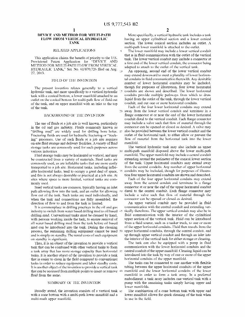
( 57 ) ABSTRACT A vertical hydraulic tank includes an upper cylindrical section and a lower conical section , with an outlet in the lower conical section . A lower multi - path manifold is attached to the outlet , the manifold including a vertical conduit in fluid communication with the outlet and a plu rality of horizontal conduits in fluid communication with the vertical conduit . An upper multi - path manifold can also be attached to the tank with a plurality of upper horizontal conduits and a vertical conduit in fluid communication with the upper cylindrical section of the tank . Valves may be provided along the vertical conduit and the horizontal con duits to regulate flow of material through the conduits . A pump may be connected to either the upper manifold or the lower manifold , or both by way of a pump conduit . Multiple tanks can be connected together by way of tubing between the manifolds of each tank .
14 Claims , 13 Drawing Sheets
- 60
76 35 * 14
62 44 80 70 84
35
52
26 31
16 64 28
18 30 32

US 9 , 777 , 543 B2 Page 2
( 56 ) References Cited U . S . PATENT DOCUMENTS
6 , 468 , 481 B1 * 10 / 2002 Anderson . . . . . . . . . . . . . B01F 1 / 0016 422 / 261
6 , 555 , 074 B1 * 4 / 2003 Sweet . . . . . . . . . . . . . . . . . . . A473 31 / 053 422 / 281
6 , 779 , 539 B1 * 8 / 2004 Schwamberger . . . . . . . CO2F 1 / 688 137 / 1
2008 / 0190668 A1 * 8 / 2008 Swartout . . . . . . . . . . . . . . . E21B 21 / 065 175 / 207
* cited by examiner

atent Oct . 3 , 2017 Sheet 1 of 13 US 9 , 777 , 543 B2
NASYNOXos zavaNnXYMO * * * NOSNO
* * * WAWA *
on #
WETTA DRU A
*
* *
* *
- - - - * * * oxum
OVAANNYVVMMAAAANNY MAAAANNYVMnnnAANVVVinix AAN MMAAAANNYAANNNMAAAANNNAANNYM 60 XOX * *
*
*
DW + + + + 49 . NNN * * * wu
wowo u -
W H
HHHU UUDDD IDE WORD Abi U UGOD
ann
- 20
30 32
FIG . 1
atent Oct . 3 , 2017 Sheet 2 of 13 US 9 , 777 , 543 B2
10
52 pasar 66 56 17 23
nnnnnnnnnnnnnnnnnnnnn . 28 / 32 20
1929 18
FIG . 2
U . S . Patent Oct . 3 , 2017 Sheet 3 of 13 US 9 , 777 , 543 B2
sub DANI
SNOERNO * N
12 * * Up * * * oo
# WW MTA
- - - ma
* * * * * * * *
* * * * *
Sew * * * * * 60 hwnnnnnAvWwwnnwvwwnnnn 46 .
76 ur w
ww .
* * Naon n 29 . . . 17
VIT ley 08 meno
78 - 58
* 52 40 26
22 ACTION 56moment me 20 54 28
30 32
FIG . 3

84 . company
atent
www
65
52 68
Oct . 3 , 2017
36
.
VO 40
7 1929
FIG . 4
- - - - - -
Sheet 4 of 13
18
- - - - - -
78
-
- - - - 26 66 72 56
80
wa
23 C?
+
+ + + + + + + + + + + + + + + + + + + + + + + + + + + + + + + + + + +
+ + + + + + + + +
+ + + + + + + + +
+ + + + + + + + +
+ + + + + + + + +
+ + + + + + + + +
+
nanananananananannnnnnnnnnnnnnnnnnnnnnnnnnnnnnnnnnnnnnnnnnnnnnnnnnnnnnnnnnnnnnnnnnnnnnnnnnnnnnnnnnnnnnnnnnnnnnnnnn m
US 9 , 777 , 543 B2
9 .
US 9 , 777 , 543 B2
UCL beden
9€
w
wwwwww w
wwwwww
min w
wwwww +
+
+
+
+
+
+
+
+
+
+
+
+
+
+
+
+
+
+
+
+
+
+
+
+
+
+
+
+
+
+
+
+
wwwwwwwwwwwwwwww
56
Sheet 5 of 13
wwwwwwwwwwwwwwwwwwwwwwwwwwwwwwwww
menim 66 12
FIG . 5
wwwwwwwwwwwwwwwwwwwwwwwwwwwww
weber
ago month
WARRAKKAR RAKKAR
de la
Oct . 3 , 2017
moment were the
76
you
68
one
the
94 mm
a
betona retten
som en
nnnnnnnnnnnnnnnnnnnnnnnnnnnnnnnnnnnnnnnnnnnnnnnnnnnnnnnnnnnnnnnnnnnnn
- - - - - - - - - - - - - - - - - - - - - - - - - - - - - - - - - - - - - - - - - - - - - - -
90ml
atent
- - - - - - - - - - - - - - - - - - - - - - - -
- - - -
Spod . - - - - - -
- - - - - -
-
- - - - - -
. . . - - - - - -
- - - - - - - spol . .
tenen
84
mann
46mm
97 mm

atent Oct . 3 , 2017 Sheet 6 of 13 US 9 , 777 , 543 B2
se W A AAAAAAAAAAAAAAAAAAAAAAAAAAAAAAAAAAA w wwwwwwwwwwwwwwwwwwwwwwwwwww
2 1
1 1 i
1 1 1 1 1 2
{ 32 20 I
5 5 ) 2 A zatea 08 82 2 2
1 1 1 1 1 1 1
1 i
1
SL 5 [ 5 [ 5 1 ) 2 1 2 1 2 1
i
1 1 1 1 1 1
c ) UL T
me for women 5 1 1 1
1 ? 1 2 1 1
wwwm KKKKKKKKKKKKKKKKKKKKKKKK KX
* - - - - 2 . La wwwwwwwwwwwwwwwwwww w wwwwwwwwwwwwwwwwwwwwwwwwwwwwww
gram des echo
annnrannaranning ho 10 Kelly 96 127 99 z298
32 20 35
78 80 FIG . 6A w
WATAKA
PSE JUUUUUUUUUUUUUUU 84cm 70
per 95 mm . com
- 0 00 Til mm

atent Oct . 3 , 2017 Sheet 7 of 13 US 9 , 777 , 543 B2
OL 62135 5 1 1 11
)
32 20 i i i 2
i I )
L 99729829 1971
( 78 80 $ ! 51 ! 11 ! 5 :
f
28 - vya -
- -
- -
- -
* * 5 ) wwwser V
.
18 99
1 i 2 i ci i
& Ji )
( 1 $ ! I ! kakak
89 8€ L
tika W YYYYYYYYYYYYYYYYYYYYYYYYYYYYYYYYYYYYYYYYYYYYYYY KAKAKEK 46 . the one the 19h |
| | | |
Li
II f
+ +
+
35
78 80 99 z _ g
| Li LI II | FIG . 6B C
f
1997298222 26 06 i
L V |
| . c ) T ! il f ! |
89 8€ NL | 44 |
| 16 * * * * xkxx * * * * * * *
wwwwwwwwwwwwwwwwwwwwwwwwwwwwwwwwwwww - - * * * *
* * * * * * * * * * 14 4 4 4 4 4144
46 91 irisininin MYYTY
+ + EEEEEEEEEELEEEEEE
95 + + + + + + + + + + + + + + + + + +
+ + + + + + + + + + + + + + + + + + +
U . S . Patent Oct . 3 , 2017 Sheet 8 of 13 US 9 , 777 , 543 B2
movie
ni noinnit risinin Wuuuuuuu . .
1 + ELEEEEEE
min * 2
????????????????
Home 96 innsinin wwwvwwii
Que ho FIG . 7
120
11111111111111111111111111111 wwwwwwwwwwww wwwwwwwwwwwwww
EEEEEE I 300
BV

U . S . Patent Oct . 3 , 2017 Sheet 9 of 13 US 9 , 777 , 543 B2
??? 111111111111
* 1
1 1 1 1 1 1 1 1
1 1 1 1 1 1 1 1 ?????????????????????????????????????????????????????????????? mmmmmmmmmmmmmmmmmmmmmmmmmmmmmmmmmmmmmmmmmmmmmmmmmmmmmmmmmmmmmmmm 1 1 1 1 1 1 1 1 = = = = = = = = = = = = = = = = = * EEEEEEEEEEEEEEEEEEE
1 1 1 1 1 1 1 1
1 1 1 1 1 1 1 1 1 1 1 1 1 1 1 1 krrrrrr 1 1
"
??? · · ?? ·
???
? - - . . .
23 2 ] FIe 84
3
?? ?? | 5 | 55 : : : :
? |
: : : : : : : : : : : : : : : : : : : : : : : : : : : : : : :
wwwwwwwwwwwwwwwwwwwwwwwwwwwwwwwwww wwwkrwayiyats ?? " | !
ji ! t !
24 ??
tji ji ji ti li 1 ? t !
??? ! ! ??? ! ! } ! } }
1
3
? ? ?? 1986 ??? 1
* ?i
& wwn
i ! !
| i ! !
? ! !
??? ! ! ??? ! ! ! ! !
: ti ji ti ti li
? ??? ! ! ; ! " ; } ! ! !
AnswmkLL
tasar ? # Injurn )
. . . - . . . $ - . . . . . . . . ?? . . . . . .

U . S . Patent Oct . 3 , 2017 Sheet 10 of 13 US 9 , 777 , 543 B2
+ + + + + + + + + + + + + + + + + + + + + + + + + + + + - EEEEEEEEEEEEEEEEEEEEEEEEEEEEEEEEEEEEEEEEEEEE + + + + + + + + + + + + + + + + + + + mmmm ?????????????????
wwwwwwwwwwwwwwwwwwwwwww
A
32 20
78 80 78 80 = = = = wife
FIG . 8B 35 28
76
99 91 modelo mimpinan wwwser
KAYNAK MAKANA 120 5
) (
2 2
1 1 1 I
I 1 & ( 1 Xhehen 51
5 1 ) 0
10 21 RI 1 II 1 (
$ * 7 - - - -
1 ( 51
5 1 5 1 ) 1
1 1 1 2
12 | 52
( 1
51 5 ? ! ? 1
1 1 W
* * * * * * * * * * * * * * * * KEITIKLI ???????????? ww
* * * * * * * A 2 1101111111111111111111111111
de pomportam

U . S . Patent Oct . 3 , 2017 Sheet 11 of 13 US 9 , 777 , 543 B2 m
ha IIIIIIII in + + + + + + + + + + + + + + + + + + + + + + + + + + + + + + + + + + + + + + + + + + IIIIIIIIIIIIS V
III
1 - 11
bb
UUUUUUUUUUUU
51 51
1 2 I 1 21 II 1
( ) 1 ( 11
78 80 A kr 2009 Hand !
52 5 i 51
) 2
16 U 1
1
- - - - FIG . 8C * 281 * 1
( ( f 51
5 1 5 ?
35 1
1 936 40 f 1 1 2
Zi 1 & vow
65 ( 11 51 51
? 11 ??????? w
d ÁRAKARAKTÁRKRRijal LUXXXXXXX 120
32 20
78 80 10
35
65 46 POPULER 1111111111111111111111111111111111111111111111111111111111111111111111111111111 11111111 1 111111 *
wwwwwwwwwwwwwwwwwwwwwwwwwwwwwwwwwwwwwwwwwwwwwwwwwwwwwwwwwwwwwwwwwwwww

U . S . Patent Oct . 3 , 2017 Sheet 12 of 13 US 9 , 777 , 543 B2
MMMM
DI 96
96
12
99 2298 32 20
- 64
FIG . 8D 28
moto como - con for me *
wika - www 1 KK ikimit TKP undante ng = = = - * = = = =
wwwwwwwwwwwwwwwwwwwwwwww - , * - = = Q = = = = wwwwwwwwwwwwwwwwwwwwwwwwwwwwwww
8 9188121 1696 L . 9974982
96 RRRRRRRRRRrinin m 120 -
32 20
78 80 64 ang
35
9 P 8 9 8€ 39
* * * * * * * * * 524242424242 % EZETTIIIII60111111111111111111111
* wwwwwwwwwwwwwwwwwwwwwwwww wwwwwwwwwwwwwwwwwwwww

herer 09
wwwwwwwwwwwwwwwwwwwww logo online assis
20000 . ooo wwwwwwwwwww
pom odoro pomowy 6000000000000000 0000 00000000000000 0000000000000 0000 WWW000000000000000009 wwwwwwwwwwwwwwwwwwwwwwwwwwwwwwwwww w wwwwwwwwwwwwwwwwwwww
Remote mountry no
So Winterhungen w wwwwwwwwwwwwwwwwwwwwwwwwwwwwwwwwwwwwwwwwwwwwwwwwwwwwwwwwwwwwwwwwwwwwwwwwwww 000000000000000000000000000000000000000000000000000000000000000000000000000000
www wwwwwwwwwwwwwwwwwwwwwwwwwwwwwwwwwwwwwwwwwwwwwwwwwwwwwwwwwww wwwwwwwwwwwwwwwwwwwwwwwwwwwwwwwwwwwwwwwwwwwwwwwwwwwwwwwwwwwwwwwwwwwwwwwwwwwww
wwwwwwwwwwwwwwwwwwwwwwwwww w wwwww SORE
Viu MITME Tin
UUUUUU
XYL WWWWWWWWWWWWWWWWWWWWWW Catania gondola intercomm anand
W EEKEREKEKEKEKEKEKEKEKEKEKKEL WW W W W W WWWW * * * * * * * * * * * * * * W * * * * * * * * * * * * * * * * * * * * * * * * * * 2W
99999999999999999999999999999999999999999999999
wwwwwwwww wwwwwwwwwwwwwwwwwwwwwwwwwwwwwwwwwwwwww
Economic * * * *
: 11 W * * * * * * * * * * * * *
20000 * * * * * * * *
40000W * * * * * * * * * * * * * * * * * * * * * * * * * * * * * * * * * * * * * * *
WWwwwwwwwwwwwwwwwwwwwwwwwwwwwwwww 94 rasane Ressouspuoges AWAU
FIG . 9
Seancannot : 1 MONTANA Rubuwwwwwwwwwwwwwwwwwwwwwwwwwwwwwwwwwwwwwwwwwwwwwwwwwwwwwwwwwwwwwwwwwwwwwwwwwwwwwwwww
& 10 wwwwwwwwwwwwwwwwwwwwwwwwwwwwwwwwwwwwwwwwwwwwwwwwwwwwwwwwwwwwwwwwwwwwwwwwwwwwwwwwwwwwwwwwwww
sustado am 00 120
- 35
09
US 9 , 777 , 543 B2 Sheet 13 of 13 Sheet 13 of 13 Oct . 3 , 2017 U . S . Patent
US 9 , 777 , 543 B2
DEVICE AND METHOD FOR MULTI - PATH More specifically , a vertical hydraulic tank includes a tank FLOW FROM VERTICAL HYDRAULIC having an upper cylindrical section and a lower conical
TANK section . The lower conical section includes an outlet . A multi - path lower manifold is attached to the outlet .
RELATED APPLICATIONS The lower manifold may include a lower vertical conduit that is in fluid communication with the outlet of the vertical This application claims the benefit of priority to the U . S . tank . The lower vertical conduit may include a connector at Provisional Patent Application for “ DEVICE AND a first end of the lower vertical conduit , the connector being METHOD FOR MULTI - PATH FLOW FROM VERTICAL adapted to attach to the outlet of the vertical tank . HYDRAULIC TANK , ” Ser . No . 61 / 870 , 726 filed on Aug . , 10 27 , 2013 . An opposing , second end of the lower vertical conduit may extend downward to meet a plurality of lower horizon
FIELD OF THE INVENTION tal conduits in fluid communication therewith . Any desirable number of lower horizontal conduits may be included ,
The present invention relates generally to a vertical though for purposes of illustration , four lower horizontal hydraulic tank , and more specifically to a vertical hydraulic 15 conduits are shown and described . The lower horizontal tank with a conical bottom , a lower manifold attached to an conduits provide multiple pathways from which to draw outlet on the conical bottom for multi - path flow of fluid out liquid from the outlet of the tank , through the lower vertical of the tank , and an upper manifold with an inlet to the top conduit , and out one or more horizontal conduits . of the tank . Each of the four lower horizontal conduits may extend
20 away from the lower vertical conduit and terminate in a BACKGROUND OF THE INVENTION flange connector at or near the end of the lower horizontal
conduit distal to the vertical conduit . Each flange connector The use of fluids at a job site is well known , particularly may include a valve such that flow of material through the
in the oil and gas industry . Fluids commonly known as connector can be opened or closed as desired . A valve may “ drilling mud ” are widely used for drilling bore holes . 25 also be provided between the lower vertical conduit and the Fracturing fluids are used for hydraulic fracturing or “ track - outlet of the horizontal tank , to either allow or prevent the ing " processes . Use of such fluids at a job site requires flow of material from the horizontal tank into the lower on - site fluid storage and delivery facilities . A variety of fluid manifold . storage tanks are commonly used for such purposes across The vertical hydraulic tank may also include an upper various industries . 30 multi - path manifold disposed above the lower multi - path
Fluid storage tanks may be horizontal or vertical , and may manifold . The upper manifold may include a central conduit be constructed from a variety of materials . Steel tanks are extending around the perimeter of the conical lower section commonly used , as are inflatable tanks that are more easily of the tank . Upper horizontal conduits may extend away transported to a job site . Horizontal tanks , including inflat - from the central conduits . Any number of upper horizontal able horizontal tanks , tend to occupy a great deal of space , 35 conduits may be included , though for purposes of illustra and this is not always desirable or practical at a job site . At tion four upper horizontal conduits are shown and described . sites where space is more limited , vertical tanks are com Each of the four upper horizontal conduits may extend monly used . away from the central conduit and terminate in a flange
Steel vertical tanks are common , typically having an inlet connector at or near the end of the upper horizontal conduit path allowing flow into the tank , and an outlet for allowing 40 distal to the central conduit . Each flange connector may flow out of the tank . Such tanks are used individually , and include a valve such that flow of material through the when the tank and connections are fully assembled , the connector can be opened or closed as desired . direction of flow to and from the tank is limited . An upper vertical conduit may be provided in fluid
It is commonplace in drilling practices in the oil and gas communication with the central conduit and extending ver industry to switch from water based drilling mud to oil based 45 tically therefrom . The upper vertical conduit may also be in drilling mud . Conventional tanks must be cleaned by hand , fluid communication with the interior of the cylindrical with persons working inside the tank , to ensure removal of upper section of the vertical tank . Fluid can be introduced all water based drilling mud from the tank before oil based from a fluid source , such as a tanker truck , to one or more mud can be introduced into the tank . During the cleaning of the upper horizontal conduits . Fluid then travels from the process , the remaining drilling equipment cannot be used 50 upper horizontal conduits , through the central conduit , and and is simply on standby . The rental costs of such equipment up through upper vertical conduit and through an inlet into on standby is significant . the interior of the vertical tank for either storage or cleaning .
Thus , it is an object of the invention to provide a vertical The tank can also be equipped with a pump in fluid tank that can be combined with other vertical tanks to form communication with the lower horizontal conduits and the a tank array that has more storage capacity than horizontal 55 central conduit of the upper manifold . Cleaning liquid can be tanks . It is another object of the invention to provide a tank introduced into the tank by way of one or more of the upper that is easier to clean in the field compared to conventional horizontal conduits of the upper manifold . tanks in order to reduce equipment and labor standby costs . The tanks can be connected to one another with flexible It is another object of the invention to provide a vertical tank tubing between the upper horizontal conduits of the upper that can be accessed from multiple points to insert or remove 60 manifold and the lower horizontal conduits of the lower fluid from the same . manifold in order to form a tank array . In a preferred
embodiment , a tank array includes one vertical tank with a SUMMARY OF THE INVENTION pump with the remaining tanks simply having upper and
lower manifolds . Broadly stated , the invention consists of a vertical tank 65 The combination of a cone bottom tank with upper and
with a cone bottom with a multi - path lower manifold and a lower manifold allows for quick cleaning of the tank when multi - math upper manifold . in use in the field .

US 9 , 777 , 543 B2
BRIEF DESCRIPTION OF THE DRAWINGS of a vertical hydraulic tank system of the present invention equipped with a lower manifold 10 . The vertical tank 12 is
The novel features of this invention , as well as the shown in dashed lines to facilitate a complete view of lower invention itself , both as to its structure and operation , will manifold 10 and includes a cylindrical upper section 60 and best be understood from the accompanying drawings , taken 5 a conical lower section 62 . Conical lower section 62 termi in conjunction with the accompanying description , in which nates at an outlet 64 through which material may be passed similar reference characters refer to similar parts , and in from vertical tank 12 . Positioned below vertical tank 12 is an which : exemplary lower manifold 10 of the present invention . FIG . 1 is a side perspective view of one embodiment of Lower multi - path manifold 10 includes a lower vertical a vertical tank with a lower multi - path manifold ;
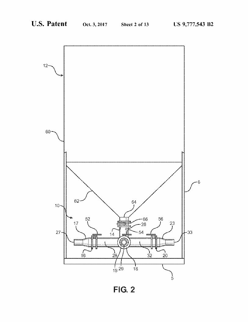
FIG . 2 is a side elevation view of the vertical tank of FIG . c 10 conduit 26 having an upper end and a lower end . The upper end of lower vertical conduit 26 terminates in a connector
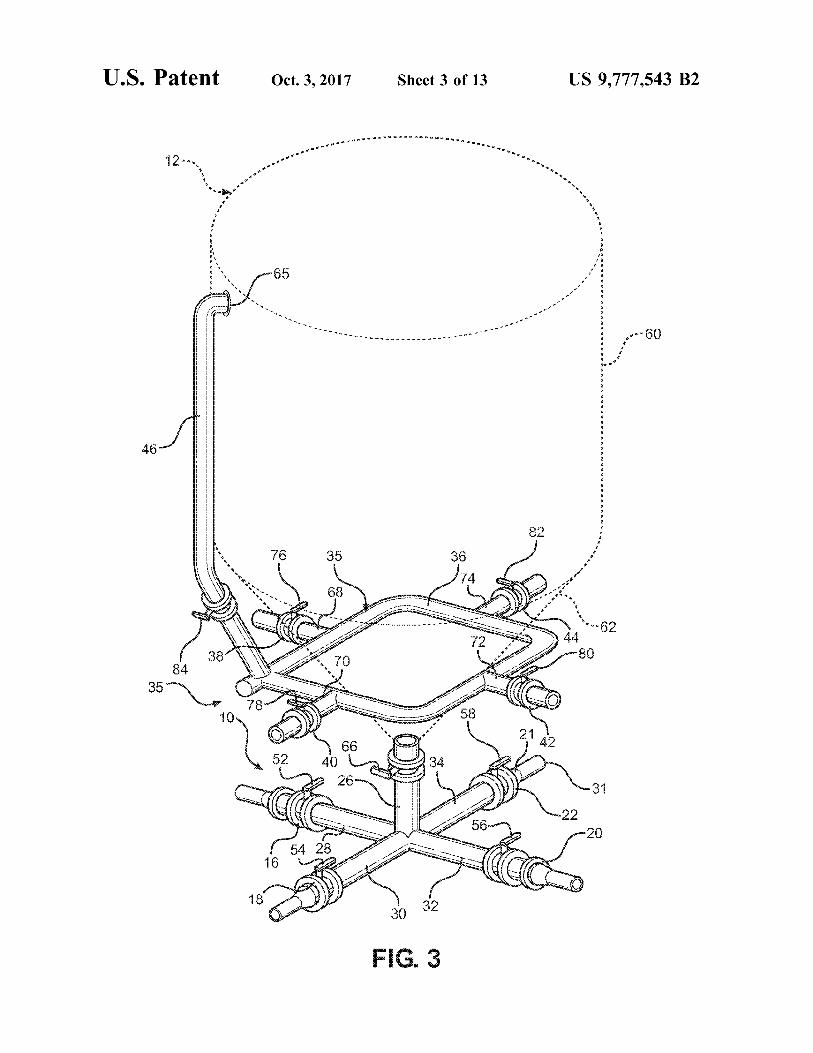
FIG . 3 is a side perspective view of an embodiment of a 14 . Connector 14 is adapted to mate with the structure of vertical tank with lower manifold , the vertical tank also outlet 64 , such that lower manifold 10 can be attached to including an upper multi - path manifold ; vertical tank 12 and is in fluid communication with the same .
FIG . 4 is a side elevation view of the vertical tank of FIG . 15 A lower vertical conduit valve 66 is provided on the lower vertical conduit 26 and can be opened or closed to either
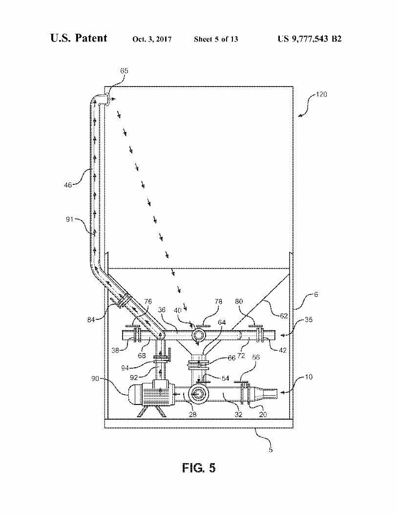
FIG . 5 is a side view of a vertical tank equipped with a allow flow of material from vertical tank 12 into the lower lower manifold , an upper multi - path manifold and a pump manifold 10 or to prevent that flow of material into the lower and showing the path of circulation of fluid through the manifold 10 . vertical tank during a cleaning cycle ; 20 Four lower horizontal conduits 28 , 30 , 32 , and 34 meet at
FIG . 6a is a side view of a plurality of vertical tanks the bottom of lower end of lower vertical conduit 26 . The having upper and lower manifolds and showing the pathway horizontal conduits 28 , 30 , 32 and 34 are each in fluid of drilling fluid from a truck to a first vertical tank in order communication with lower vertical conduit 26 , such that to fill the first vertical tank ; material flowing from vertical tank 12 into lower vertical
FIG . 6b is a side view of a plurality of vertical tanks 25 conduit 26 can flow into one or more of the lower horizontal having upper and lower manifolds and showing the pathway conduits 28 , 30 , 32 and 34 . Once material has flowed into of drilling fluid from a truck to a second vertical tank , one of the lower horizontal conduits 28 , 30 , 32 or 34 it can through the upper manifold of the first vertical tank in order be directed to one or more other vertical tanks or other to fill the second vertical tank ; desired locations , as set forth .
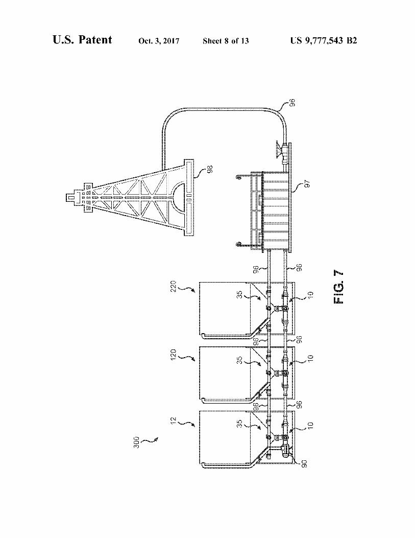
FIG . 7 is a side view of a plurality of vertical tanks in fluid 30 Each of lower horizontal conduits 28 , 30 , 32 , and 34 communication with a drilling mud mixing station which is includes a corresponding flange connector 16 , 18 , 20 and 22 in turn in fluid communication with a drilling rig ; respectively . The flange connectors 16 , 18 , 20 and 22 are
FIG . 8a is a side view a first vertical tank in fluid attached to the ends of the lower horizontal conduits 28 , 30 , communication with a second vertical tank and is also in 32 and 34 to allow additional conduits or flexible tubing 96 fluid communication with a drilling mud mixing station and 35 ( not shown in this Figure ) to be connected to one or more of showing drilling fluid being delivered from the mud mixing the horizontal conduits 28 , 30 , 32 or 34 , thereby providing station to the first vertical tank by way of the upper manifold a path for material flow away from vertical tank 12 . Each of of the second vertical tank and the upper manifold of the first the flange connectors 16 , 28 , 20 and 22 also includes a vertical tank ; corresponding horizontal conduit valve 52 , 54 , 56 and 58
FIG . 8b is a side view a first vertical tank in fluid 40 respectively . The horizontal conduit valves 52 , 54 , 56 and 58 communication with a second vertical tank and is also in may be open or closed in various combinations to prevent fluid communication with a drilling mud mixing station and flow from the horizontal conduits 28 , 30 , 32 and 34 ; to direct showing drilling fluid being delivered to the mud mixing flow of a material from one or more horizontal conduits to station from the first vertical tank by way of the lower another destination , such as a second vertical tank , a mud manifold of the first vertical tank and the lower manifold of 45 mixing station , a tanker truck or a drilling mud pit ; or to the second vertical tank ; receive material from another material source , such as
FIG . 8c is a side view of a first vertical tank in fluid another vertical tank , a tanker truck or a mud mixing station . communication with a second vertical tank and is also in It is to be appreciated that the connectors contemplated fluid communication with a drilling mud mixing station and herein are not limited to flange style connectors , but include showing drilling fluid being delivered to the mud mixing 50 a wide variety of coupling connectors known in the art . station from the second vertical tank by way of the lower As shown in FIG . 1 , each of the lower horizontal conduits manifold ; 28 , 30 , 32 , and 34 are at ninety - degree angles to the two
FIG . 8d is a side view of a first vertical tank in fluid adjacent conduits . It should be understood , however , that the communication with a second vertical tank and is also in lower horizontal conduits 28 , 30 , 32 and 34 can extend away fluid communication with a drilling mud mixing station and 55 from lower vertical conduit 26 at any desired angles . It showing a cleaning cycle of the second vertical tank using should also be understood that the present invention is not the lower manifold , pump and upper manifold of the first limited to four lower horizontal conduits when more or less vertical tank and the upper manifold and lower manifold of horizontal conduits could be used within the spirit of this the second vertical tank ; and invention .
FIG . 9 is a perspective view of a tank array of vertical 60 FIG . 2 shows the device of FIG . 1 from a side elevation tanks connected together with flexible tubing at the upper view , with some of the various components described above manifold and the lower manifold . with respect to FIG . 2 visible . In addition , Tank 12 is shown
with solid lines and is also shown suspended over a base 5 DETAILED DESCRIPTION and connected to base 5 with a frame 6 . The base 5 and
65 frame 6 provide a stable platform to suspend the lower Turning to the drawings , wherein like numerals indicate manifold 10 above the ground ( not shown ) . Horizontal
like parts , FIG . 1 is a perspective view of one embodiment conduits 28 and 32 each have a taper 17 , 19 , 21 and 23 and

US 9 , 777 , 543 B2
a tip 27 , 29 , 31 and 33 ( note taper 21 and tip 31 not visible liquid can be introduced into the tank by way of the upper in FIG . 2 ) . The tapers 17 , 19 , 21 and 23 facilitate connecting manifold by connecting a fluid source , such as a tanker truck a flexible tubing 96 ( not shown ) or other pipe style device to ( not shown ) , to one of the upper horizontal conduits ( 68 , 70 , receive material or fluid from the horizontal conduits 28 , 30 , 72 or 74 ) of an upper manifold 35 . ( As can be seen in FIGS . 32 and 34 . 5 6A and 6B ) To conduct a cleaning cycle , the valves 66 , 94 ,
In some embodiments of the present invention , a multi - and 84 are each placed in the open position with all path upper manifold 35 is also provided . As shown in FIG . remaining valves being placed in the closed position . Once 3 , multi - path upper manifold 35 is preferably located above so configured , pump 90 draws cleaning fluid ( not shown ) lower manifold 10 and is not in direct fluid communication along a pathway 91 from the outlet 64 of tank 120 , through therewith . 10 the lower manifold 10 , through the pump 90 , through the Multi - path upper manifold 35 preferable includes a cen - pump conduit 92 , through the central conduit 36 , through the
tral conduit 36 , which extends around the perimeter of upper vertical conduit 46 , and finally back into the inlet tank conical lower portion 62 of vertical tank 12 . Central conduit 65 of the tank 120 . As configured , the cleaning fluid will 36 may be roughly square , as shown in FIG . 3 , or may be continue to circulate through the tank 120 until the tank 120 circular or provided in any other suitable shape . Extending 15 is clean . Such a cleaning cycle allows the tank 120 to quickly away from central conduit 36 are a number of upper hori - be cleaned when switching from water based drilling mud to zontal conduits 68 , 70 , 72 , and 74 . The upper horizontal oil based drilling mud . conduits 68 , 70 , 72 and 74 are in fluid communication with FIG . 6a is a side view of a first tank 12 configured with central conduit 36 . an upper manifold 35 and a lower manifold 10 connected to
Each of upper horizontal conduits 68 , 70 , 72 , and 74 20 a second tank 120 configured with an upper manifold 35 , a includes a corresponding upper conduit connector 38 , 40 , lower manifold 10 and a pump 90 . A tanker truck 95 is 42 , and 44 , respectively . These upper conduit connectors 38 , connected to the second tank 120 by way of a flexible tubing 40 , 42 and 44 each include an upper horizontal conduit valve 96 or other flexible piping to upper horizontal conduit 68 and 76 , 78 , 80 , and 82 respectively , which can be opened or secured with the upper horizontal conduit connector 38 . closed to control the flow of material into or out of the upper 25 Using the upper manifolds 35 of the first tank 12 and second horizontal conduits 68 , 70 , 72 and 74 . Thus , by operation of tank 120 , material can be delivered from the tanker truck 95 the upper horizontal conduit valves 76 , 78 , 80 and 82 , a user to the first tank 12 , even when the tanker truck 95 cannot be may also control flow of material or fluid into central conduit directly connected to the first tank 12 . In FIG . 6a , valves 76 36 or out of central conduit 36 . Material may flow into and 84 of the first tank 12 and valves 76 and 80 of the second central conduit 36 from any desired location , through one or 30 rank 120 are each in the open position while all other valves more of upper conduit connectors 38 , 40 , 42 , or 44 by in the first tank 12 and second tank 120 are in the dosed connecting flexible tubing 96 ( shown in FIGS . 6a through 9 ) position A flexible tubing 96 connects upper horizontal between a source of material such as a tanker truck 95 conduit 68 of the first rank 12 to the upper horizontal conduit ( shown in FIGS . 6a and 6b ) , mud mixing station 97 ( shown 72 of the second tank 120 and allows the upper manifold 35 in FIGS . 7 through 8 ) or a second vertical tank ( shown in 35 of the first tank 12 to be in fluid communication with the FIGS . 6 through 9 ) and one or more upper conduit connec - upper manifold 35 of the second tank 120 . Once so config tors 38 , 40 , 42 or 44 . ured , the tanker truck 95 is in fluid communication with the
In an embodiment , central conduit 36 is also in fluid manifold 35 of the first tank 12 through the upper manifold communication with an upper vertical conduit 46 , which 35 of the second tank 120 and can deliver material along extends from the central conduit 36 . Upper vertical conduit 40 pathway 91 , raising the level 13 of the material in the first 46 preferably extends upward to at or near the top of vertical tank 12 . tank 12 , whereupon upper vertical conduit 46 opens into the FIG . 6b is a side view of a first tank 12 configured with interior of vertical tank 12 by way of an inlet 65 . an upper manifold 35 and a lower manifold 10 connected to
FIG . 4 shows the device of FIG . 3 from a side elevation a second tank 120 configured with an upper manifold 35 , a view , with the various components described above with 45 lower manifold 10 and a pump 90 . A tanker truck 95 is respect to FIG . 3 visible . An upper vertical conduit valve 84 connected to the second tank 120 by way of a flexible tubing is in fluid communication with the upper vertical conduit 46 96 or other flexible piping to upper horizontal conduit 68 and and can be opened and closed to control the flow of material secured with the upper horizontal conduit connector 38 . from the central conduit 36 through the upper vertical After the first tank 12 is filled with material as set forth conduit 46 and into the interior of the vertical tank 12 . 50 above , a user simply has to dose valve 80 of the second tank
FIG . 5 is a side view of an alternative embodiment of a 120 and also open valve 84 of the second tank 120 . Once so vertical tank 120 equipped with a lower manifold 10 , an configured , material can flow along pathway 91 from tanker upper manifold 35 and a pump 90 . The pump 90 is con - truck 95 through the flexible tubing 96 , into the upper nected to horizontal conduit 28 in lieu of taper 17 and tip 27 horizontal conduit 68 of the upper manifold 35 of the second and is in fluid communication with the lower horizontal 55 tank , into the upper vertical conduit 46 , through the inlet 65 conduits 28 , 30 , 32 and 34 of the lower manifold 10 . The and into the second tank 120 to fill the tank 120 to level 13 . pump 90 is also in fluid communication with the central FIG . 7 is a side view of a first tank 12 , a second tank 120 conduit 36 of the upper manifold 35 by way of the pump and a third tank 220 all of which are connected to one conduit 92 . A pump conduit valve 94 is in fluid communi - another by way of flexible tubing 96 between the upper cation with the pump conduit 90 . When the pump conduit 60 manifolds 35 of each tank and by way of flexible tubing 96 valve 94 is closed , no fluid or material can pass from the between the lower manifolds 10 of each tank in order to lower manifold 10 to the upper manifold 35 . When the pump create a tank array 300 . In addition , flexible tubing 96 conduit valve 94 is open , fluid or material can pass from the connects the third tank 220 to a mud mixing station 97 . The lower manifold 10 to the upper manifold 35 . mud mixing station 97 is in turn , connected to a drilling rig As can be seen in FIG . 5 , the tank 120 can be configured 65 98 . Drilling fluid can be created in the mud mixing station
to engage in a cleaning cycle during which a clean fluid can 97 and delivered to each of the three tanks forming the tank circulate through the tank 120 in a closed loop . Cleaning array 300 through the flexible tuning 96 and the upper

US 9 , 777 , 543 B2
manifolds 35 of each of the tanks in order to be stored for material can then be delivered from the first tank 12 to the later use by the drilling rig 98 . When needed for use , the mud mud mixing station 97 . To switch the flow of material to the mixing station draws drilling fluid stored in the tanks 12 , 120 mud mixing station 97 from the second tank 120 to the first and 220 through their respective lower manifolds 10 and tank 12 , lower vertical conduit valve 66 and lower conduit into the mud mixing station 97 , The drilling fluid is then 5 valve 56 of the second tank 120 are dosed . Next , in the first drawn from the mud mixing station 97 to be used in drilling vertical tank 12 lower conduit valve 52 is dosed and the activities by the drilling rig 98 . Pump 90 in the first tank 12 lower vertical valve 66 is placed in the open position . Once can be used to assist in the delivery of drilling fluid to the so configured , material can flow along pathway 91 through mud mixing station 97 or to assist in the delivery of drilling the outlet 64 of the first tank , into the lower vertical conduit fluid to the upper manifolds 35 of the three tanks in tank 10 26 , then into the lower horizontal conduit 32 of the first tank , ar array 300 . then into the flexible tubing 96 until the material reaches the
FIG . 8a is a side view a first vertical tank 12 in fluid mud mixing station 97 . Once at the mud mixing station 97 , communication with a second vertical tank 120 and is also the material can be used by a drilling rig 99 ( not show ) in fluid communication with a drilling mud mixing station Once the tanks 12 and 120 had delivered their stored 97 and showing the pathway 91 of flow of a material , such 15 material to the mud mixing station 97 , it may be necessary as drilling fluid , being delivered from the mud mixing to clean the tanks 12 and 120 . Turning to FIG . 8d , a cleaning station 97 to the second vertical tank 120 by way of the cycle for the first tank 12 is generally depicted using the upper manifold 35 of the first vertical tank 12 and the upper pump 92 of the second tank . First a cleaning solution is manifold 35 of the second vertical tank 120 . Upper conduit introduced into the second tank 120 ( see generally FIG . 6A ) 72 of the first tank 12 is connected to the mud mixing station 20 Next , the second tank 120 should be configured to have 97 by way of a flexible tubing 96 . Lower conduit 32 is also lower conduit valve 56 , pump conduit valve 94 , and upper connected to the mud mixing station 97 by way of a flexible conduit valve to be in the open position with all other valves tubing 96 . Upper conduit 68 of the first tank 12 is connected in the second tank 120 in the close position . The first tank 12 to upper conduit 72 of the second tank 120 by way of a should be configured with the upper conduit valve 76 , the flexible tubing 96 . Similarly , lower horizontal conduit 28 of 25 upper vertical conduit valve 84 , the lower vertical conduit the first tank is connected to the lower horizontal conduit 32 valve 66 and the lower horizontal conduit valve 28 all in the of the second tank 120 by way of flexible tubing 96 , Once open position . Once so configured , pump 90 can be activated so connected , the upper manifolds 35 of both the first tank to draw the cleaning fluid along pathway 91 from the first 12 and second tank 120 are each in fluid communication tank 12 , into the upper vertical conduit until the fluid exists with the mud mixing station 97 and the lower manifolds 10 30 the first tank 12 from the lower horizontal conduit 28 and of both the first tank 12 and second tank 120 are each in fluid into the flexible tubing 96 . The material is then drawn by the communication with the mud mixing station 97 . Also , the pump 90 into the lower manifold 10 of the second tank 120 second tank 120 is equipped with a pump . Pump conduit 92 at the lower horizontal conduit 32 along the pathway 91 , connects and is in fluid communication with the upper through the pump 90 and the pump conduit 92 into the upper manifold 35 and the lower manifold 10 . In order to pass 35 manifold 35 of the second tank 120 . The fluid then exits the material , such as drilling fluid , from the mud mixing station upper conduit 72 of the second tank 120 into a flexible 97 to the second tank 120 , upper conduit valves 76 and 80 tubing 96 until it reaches the upper conduit 68 of the upper of the first tank 12 are each placed in the open position with manifold 35 of the first tank . The cleaning fluid then travels all other valves in the first tank 12 placed in the closed up through the upper vertical conduit 46 until it re - enters the position . In the second tank 120 , upper conduit valve 80 and 40 first tank 12 at the inlet 65 , thereby completing a circulation upper vertical conduit valve 84 are in the open position with loop . The pump 90 continues to circulate the cleaning fluid all other valves in the second tank 120 in the closed position . along pathway 91 until the first tank 12 is clean . Unlike Once so configured , material can pass from the mud mixing conventional tanks used in the oil and gas industry , no station 97 along pathway 91 through the upper manifold 35 persons are required to enter into the first tank to complete of the first tank 12 and into the upper manifold 35 of the 45 the cleaning cycle . The various valves of the first 12 and second tank 120 , through the upper vertical conduit 46 and second tank 120 can be configured as set forth above to then through inlet 65 and into the second tank 120 , filling the tank conduct a cleaning cycle in the second tank 120 again 120 to level . without the need to have persons physically enter the first
Turning to FIG . 8b , in order to deliver material from the tank 12 . The cleaning cycles disclosed herein allow for a second tank 120 to the mud mixing station 97 , the lower 50 substantial reduction in time for cleaning , such as when vertical conduit valve 66 and the lower conduit valve . 56 of drilling operations require a switch from water based drilling the second tank are placed in the open position with all other mud to oil based drilling mud . valves in the second tank 120 placed in the closed position . FIG . 9 is a perspective view of a first tank 12 in between Next , the lower conduit valves 52 and 56 of the first tank 12 a second tank 120 and third tank 220 , and collectively are placed in the open position with all other valves in the 55 arranged to form a tank array 300 with a flexible tubing 96 second tank placed in the dosed position . Once so config connected to the a tank array 300 . Drilling mud 100 is shown ured , material can flow along pathway 91 through the outlet being released from the lower manifold 10 of the first tank 64 of the second tank , into the lower vertical conduit 26 , 12 into a mud pit 99 . It is to be appreciated by those skilled then into the lower horizontal conduit 32 of the second tank , in the art that oil based drilling mud is frequently discharged then into the flexible tubing 96 , then into the lower hori - 60 into mud pits . Conventional tanks need to be manually zontal conduit 28 of the first tank 12 until it exits the first cleaned with persons operating inside of the tank to remove tank 12 through the lower horizontal conduit 32 until the the remaining oil based mud . The present invention allows material reaches the mud mixing station 97 . Once at the mud quick discharge of any remaining oil based drilling mud into mixing station 97 , the material can be used by a drilling rig the mud pit 100 through use of the lower manifolds 10 of 99 ( shown in FIG . 7 ) . 65 each of the tanks 12 , 120 , and 220 and the flexible tubing 96
Turning to FIG . 8c , after all material has been delivered connecting the same in combination with the upper mani from the second tank 120 to the mud mixing station 97 , folds 35 of each of the tank 12 , 120 , and 220 . Use of the

US 9 , 777 , 543 B2 10
pump 90 shown on second tank 120 can help facilitate variety of combinations of connections and fluid paths is drawing the drilling mud 100 from each of the tanks 12 , 120 made possible by the present invention . and 220 . For example , FIG . 9 depicts a flexible tubing 96 It is further contemplated that fluid may be delivered connected to the upper horizontal conduit 70 at the upper from , or received into , any given tank via either of the upper horizontal conduit connector 40 . On each of the tanks , each 5 or lower manifolds and the associated conduits as set forth of the lower vertical conduit valves 66 are placed in the open in detail above . External pumps can be used in lieu of a position , allowing drilling mud 100 to pass from the tanks pump integrated into the tank . into the lower manifolds 10 . Lower conduit valve 56 of rank Where reference is made herein to a method comprising 220 , lower conduit valves 52 and 56 of tank 12 , and lower two or more defined steps , the defined steps can be carried conduit valve 52 of tank 120 are also placed in the open 10 out in any order or simultaneously ( except where the context position . Next , the pump conduit valve 94 of tank 120 is also excludes that possibility ) , and the method can include one or placed in the open position to enable the pump 90 to draw more other steps which are carried out before any of the the drilling mud 100 through the lower manifolds 10 of each defined steps , between two of the defined steps , or after all of the tanks into the upper manifold 35 of tank 120 . The the defined steps ( except where the context excludes that pump 90 then pushes the drilling mud 100 from the upper 15 possibility ) . manifold 35 of tank 120 to the upper manifold 35 of tank 12 While there have been shown what are presently consid by way of the flexible tubing 96 , Finally , the pump 90 pushes ered to be preferred embodiments of the present invention , the drilling mud 100 out of the upper conduit 70 through the it will be apparent to those skilled in the art that various flexible tubing 96 to a mud pit 99 . Thus , the combination the changes and modifications can be made herein without upper manifolds 35 , lower manifolds 10 , and pump allowed 20 departing from the scope and spirit of the invention . Accord the tanks 12 , 120 and 220 to be quickly drained of drilling ingly , the invention is not to be limited as except by the mud 100 without the need for persons to enter the tanks to appended claims . remove any remaining drilling mud 100 by hand . The tanks What is claimed is : 12 , 120 , and 220 are then ready to be quickly moved from 1 . A vertical tank comprising : one drilling location to the next to be filled with a water 25 a tank having a cylindrical upper section having a radius based drilling mud whereas conventional tanks typically and a conical lower section extending from the cylin used in the oil and gas industry would still be in the slow drical upper section to a bottom ; process of being cleaned by hand to ensure total removal of an outlet in the conical lower section and centered at the the drilling mud 100 . bottom of the conical lower section ; and As shown in the Figures , the various manifolds are 30 a lower manifold having
connected via flexible tubing 96 that allows fluids to flow a lower vertical conduit in fluid communication with between the various vertical tanks 12 . It is contemplated that the outlet of the tank with a first end and an opposing rigid pipe or conduit may be used in the connection of the second end , the first end connected to the outlet such tanks , and that any desired flow pattern may be established that the opposing second end extends downward between the various manifolds of the vertical tanks 12 . The 35 directly beneath the outlet , flow patterns depicted herein are merely meant to be illus a plurality of lower horizontal conduits directly con trative of how the upper manifold and lower manifolds can nected to and extending away from the second end of be used in combination with cone bottom tanks and a pump the lower vertical conduit , each having a length and to fill , drain , or clean either an individual tank or an array of each terminating in an end and in fluid communica tanks . tion with the lower vertical conduit , wherein the
It will be appreciated from the foregoing description that length is less than the radius , a plurality of tanks having the present lower manifold 10 a lower vertical conduit valve connected to and in fluid and / or upper manifold 35 included therewith may be communication with the lower vertical conduit , and arranged to provide a variety of flow patterns into and out of a plurality of lower horizontal conduit valves corresponding the tank . For example , the presence of four lower horizontal 45 in number to the plurality of lower horizontal conduits conduits in the of the manifolds , in some embodiments of wherein each lower horizontal conduit valve is connected to the present device , allows for ease of connecting flow paths and in fluid communication with one of the lower horizontal between tanks with minimal repositioning of the tanks , and conduits allows a user to take maximum advantage of a plurality of an upper manifold having tanks when factors at a job site limit the placement of tanks 50 a central conduit surrounding a perimeter of the conical in the area . lower section ;
The use of various upper conduit horizontal and vertical a plurality of upper horizontal conduits connected to and and lower conduit horizontal and vertical valves in associa extending away from the central conduit , terminating in tion with the plurality of conduits associated with the lower an end and in fluid communication with the central manifold or upper manifold also allow for creation of 55 conduit ; conduit ; custom flow paths through a variety of tanks in a wide an upper vertical conduit with a first end connected to and variety of configurations . Fluid exiting one tank may be in fluid communication with the central conduit and a directed to a second tank , or divided among more than one second end connected to and in fluid communication other tank . Alternatively , fluid exiting one tank may be with an inlet in the cylindrical upper section of the tank ; combined with the flow from a second tank to increase the 60 an upper vertical conduit valve in fluid communication amount of fluid ultimately delivered by the plurality of with the upper vertical conduit and located on the upper tanks . Fluid from a first tank may be directed to the manifold vertical conduit between the central conduit and the of a second tank , for example , where the fluid exiting the inlet of the tank ; and second tank combines with the stream from the first tank . In a plurality of upper horizontal conduit valves in fluid addition , fluid from one tank may be directed to the upper 65 communication with the plurality of upper horizontal manifold of a second tank , so that the first tank is used to conduits , wherein the plurality of upper horizontal maintain or increase the level of fluid in the second tank . A conduit valves corresponds in number to the plurality
40
m

US 9 , 777 , 543 B2 12
of upper horizontal conduits and wherein each upper 5 . The vertical tank array of claim 4 wherein one of the horizontal conduit valve is connected to one of the plurality of tanks further comprises a pump in fluid com upper horizontal conduits . munication with the lower manifold and the upper manifold
2 . The vertical tank of claim 1 further comprising a pump of each of the plurality of tanks . having a pump conduit connected adjacently to and in fluid 5 6 . A method of moving material in a vertical tank com communication with the central conduit of the upper mani - prising the steps of : fold and connected adjacently to and in fluid communication ( 1 ) providing a first vertical tank comprising with one of the plurality of the lower horizontal conduits of a tank having a cylindrical upper section and a conical the lower manifold . lower section extending from the cylindrical upper
section to a bottom , with a material stored within the 3 . The vertical tank of claim 2 wherein the pump conduit tank ; has a pump conduit valve to control flow of a material an outlet in the conical lower section and centered at the between the upper manifold and the lower manifold . bottom of the conical lower section ; 4 . A vertical tank array comprising : a base connected to the tank by a frame wherein the base a first vertical tank and a second vertical tank , the first 15 is in contact with a ground surface : vertical tank and the second vertical tank each having a lower manifold having
a cylindrical upper section and a conical lower section a lower vertical conduit in fluid communication with the extending from the cylindrical upper section to a bot outlet of the tank with a first end and an opposing tom ; second end , the first end connected to the outlet such
an outlet in the conical lower section and centered at the 20 that the opposing second end extends downward bottom of the conical lower section ; directly beneath the outlet ,
a base connected to the tank by a frame wherein the base a plurality of lower horizontal conduits directly connected is in contact with a ground surface ; to and extending away from the second end of the lower
a lower manifold having vertical conduit , each having a length and each termi a lower vertical conduit in fluid communication with 25 nating in an end and in fluid communication with the
the outlet of the tank with a first end and an opposing lower vertical conduit , wherein the length is less than second end , the first end connected to the outlet , the radius ,
a plurality of lower horizontal conduits connected to a lower vertical conduit valve connected to and in fluid and extending away from the second end of the communication with the lower vertical conduit , and lower vertical conduit , each terminating in an end 30 a plurality of lower horizontal conduit valves correspond and in fluid communication with the lower vertical ing in number to the plurality of lower horizontal conduit , conduits wherein each lower horizontal conduit valve is
a lower vertical conduit valve in fluid communication connected to and in fluid communication with one of with the lower vertical conduit , and the lower horizontal conduits ,
a plurality of lower horizontal conduit valves corre - 35 wherein the lower manifold is suspended above the sponding in number to the plurality of lower hori ground surface by the base and the frame ; zontal conduits wherein each lower horizontal con - ( 2 ) connecting the first lower horizontal conduit of the first duit valve is in fluid communication with one of the vertical tank to a mud mixing station via a flexible tubing ; horizontal conduits , ( 3 ) placing the first horizontal conduit valve in the open
wherein the lower manifold is suspended above the 40 position ; ground surface by the base and the frame ; ( 4 ) placing the second horizontal conduit valve in a closed
an upper manifold having position ; a central conduit surrounding a perimeter of the conical ( 5 ) placing the lower vertical conduit valve in an open
lower section , position ; and a plurality of upper horizontal conduits connected to 45 ( 6 ) using the mud mixing station to draw the drilling fluid
and extending away from the central conduit , termi - from the first vertical tank to the mud mixing station through nating in an end and in fluid communication with the the outlet , the lower vertical conduit , the first horizontal central conduit , conduit and through the flexible tubing
an upper vertical conduit with a first end connected to ( 7 ) providing a second vertical tank comprising and in fluid communication with the central conduit 50 a tank having a cylindrical upper section and a conical and a second end connected to and in fluid commu lower section extending from the cylindrical upper nication with an inlet in the cylindrical upper section section to a bottom , with a material stored within the of the tank , tank ;
an upper vertical conduit valve in fluid communication a base connected to the tank by a frame wherein the base with the upper vertical conduit and located between 55 is in contact with a ground surface ; the central conduit and the inlet of the tank , an outlet in the conical lower section and centered at the
a plurality of upper horizontal conduit valves corre bottom of the conical lower section ; sponding in number to the plurality of upper hori a lower manifold having zontal conduits wherein each upper horizontal con a lower vertical conduit in fluid communication with the duit valve is in fluid communication with one of the 60 outlet of the tank with a first end and an opposing upper horizontal conduits ; and second end , the first end connected to the outlet ,
a flexible tubing connecting the upper manifold of the first a plurality of lower horizontal conduits connected to and vertical tank to the upper manifold of the second extending away from the second end of the lower vertical tank such that upper manifolds of the first vertical conduit , each terminating in an end and in fluid vertical tank and the second vertical tank are in fluid 65 communication with the lower vertical conduit , communication with one another through the flexible a lower vertical conduit valve connected to and in fluid tubing . communication with the lower vertical conduit , and
13 US 9 , 777 , 543 B2
14 a plurality of lower horizontal conduit valves correspond of the conical lower section of the first vertical tank and
ing in number to the plurality of lower horizontal wherein the central conduit of the second vertical tank conduits wherein each lower horizontal conduit valve is extends around a perimeter of the conical lower section of connected to and in fluid communication with one of the second vertical tank . the lower horizontal conduits , 5 13 . The vertical tank array of claim 4 wherein the plurality
wherein the lower manifold is suspended above the of upper horizontal conduits in the first vertical tank is four ground surface by the base and the frame ; and where the plurality of upper horizontal conduits in the ( 8 ) connecting the second lower horizontal conduit of the second vertical tank is four . first vertical tank to the first lower horizontal conduit of the 14 . The vertical tank array of claim 4 further comprising second vertical tank via a second flexible tubing ; a third vertical tank having ( 9 ) placing the second horizontal conduit valve from the a cylindrical upper section and a conical lower section closed position to an open position ; ( 10 ) placing the vertical conduit valve of the second vertical extending from the cylindrical upper section to a bot
tom ; tank in an open position ; ( 11 ) placing the first lower horizontal conduit valve of the 15 an outlet in the conical lower section and centered at the second vertical tank in a closed position ; and bottom of the conical lower section ; ( 12 ) placing the second lower horizontal conduit valve of the a lower manifold having second vertical tank in a closed position ; and a lower vertical conduit in fluid communication with ( 13 ) using the mud mixing station to draw the material from the outlet of the tank with a first end and an opposing the second vertical tank to the mud mixing station through 20 second end , the first end connected to the outlet , the outlet of the second vertical tank , the lower vertical a plurality of lower horizontal conduits connected to conduit of the second vertical tank , the first lower horizontal and extending away from the second end of the conduit of the second vertical tank , the second flexible lower vertical conduit , each terminating in an end tubing , the second lower horizontal conduit of the first and in fluid communication with the vertical conduit , vertical tank , the first lower conduit of the first vertical tank , 25 a lower vertical conduit valve in fluid communication and through the flexible tubing . with the lower vertical conduit , and
7 . The vertical tank of claim 1 wherein the plurality of a plurality of lower horizontal conduit valves corre lower horizontal conduits is four . sponding in number to the plurality of lower hori
8 . The vertical tank of claim 1 wherein each of the zontal conduits wherein each lower horizontal con plurality of lower horizontal conduits has a means for 30 duit valve is in fluid communication with one of the connecting a flexible tubing or an additional conduit . horizontal conduits ; 9 . The vertical tank of claim 1 wherein each of the a flexible tubing connecting the lower manifold of the plurality of upper horizontal conduits has a means for second vertical tank to the lower manifold of the third connecting a flexible tubing or an additional conduit . vertical tank such that the lower manifolds of the first 10 . The vertical tank of claim 1 wherein the plurality of 35 vertical tank , the second vertical tank and the third upper horizontal conduits is four .
11 . The vertical tank array of claim 4 wherein the plurality vertical tank are in fluid communication with one
of lower horizontal conduits in the first vertical tank is four another through the flexible tubing connecting the first and wherein the plurality of lower horizontal conduits in the vertical tank to the second vertical tank and the flexible second vertical tank is four . tubing connecting the second vertical tank to the third
vertical tank . 12 . The vertical tank array of claim 4 wherein the central conduit of the first vertical tank extends around a perimeter
se 40
* * * * *