
-- ENGINEERING MAGAZINE
56
ISSN 0011 -7145 0 THE SOUND ENGINEERING MAGAZINE MAY 1975 $1.00 riounru,Sir //I\\ P",,,"` ii -- irir Al MM. AI MIL IN THIS ISSUE: How to Make a Simple High -Speed Tape Duplicator otion Picture Sync Systems www.americanradiohistory.com
Transcript of -- ENGINEERING MAGAZINE

ISSN 0011 -7145
0 THE SOUND ENGINEERING MAGAZINE
MAY 1975 $1.00
riounru,Sir //I\\ P",,,"` ii -- irir
Al MM.
AI MIL
IN THIS ISSUE: How to Make a Simple High -Speed Tape Duplicator
otion Picture Sync Systems
www.americanradiohistory.com
Panel full of miracle/.
Manufacturers
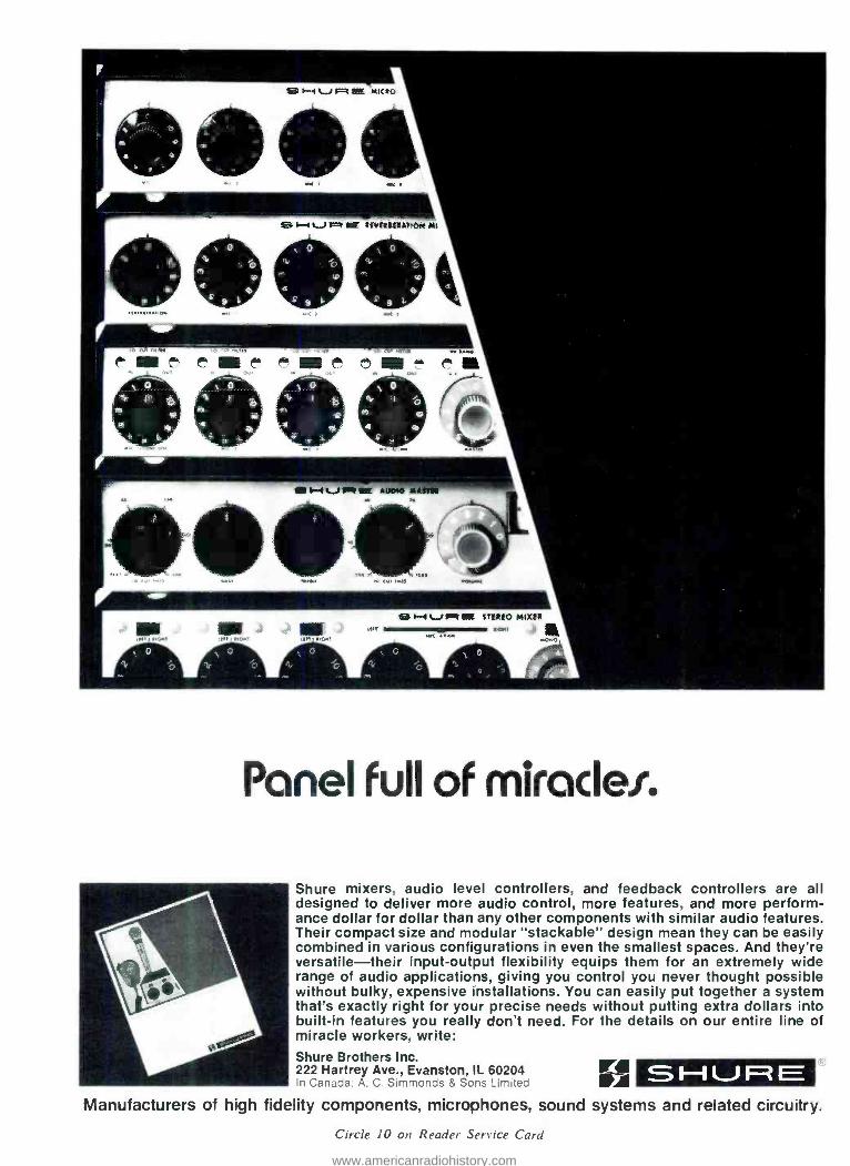
Shure mixers, audio level controllers, and feedback controllers are all designed to deliver more audio control, more features, and more perform- ance dollar for dollar than any other components with similar audio features. Their compact size and modular "stackable" design mean they can be easily combined in various configurations in even the smallest spaces. And they're versatile -their input- output flexibility equips them for an extremely wide range of audio applications, giving you control you never thought possible without bulky, expensive installations. You can easily put together a system that's exactly right for your precise needs without putting extra dollars into built -in features you really don't need. For the details on our entire line of miracle workers, write: Shure Brothers Inc. 222 Hartrey Ave., Evanston, IL 60204 In Canada: A. C. Simmonds & Sons Limited SI-IUIRE
of high fidelity components, microphones, sound systems and related circuitry.
Circle 10 on Reader Service Card
www.americanradiohistory.com

Zri month
COVERS AUDIO BAND IN ONE SWEEP.
by James Davidson, describes how a
555 timer can be adapted to create a
square -wave generator which covers 20- 20,000 Hz with no band switching.
Josef Dorner discusses the pros and cons of tape speeds in his WHY USE I5 -IPS TAPE SPEED?
Stephen Lampen visits big and small recording studios and tells us How AUDIO IS DOING IN SAN FRANCISCO.
Of Special Interest To Our Readers
During the past eight years, we have published a number of outstanding ar- ticles dealing with fundamentals and basic techniques that form the founda- tion of audio principles and practices. Since many of the issues where these articles originally appeared are no longer available (except on microfilm) and in response to the many requests from new readers for this material, we are pleased to announce that a reprint- ing program of these articles has been initiated starting in this issue. The se- ries will be entitled "The Best of db."
The first reprint is High Quality Monitor Loudspeakers by Harry F. Olson which originaly appeared in our December 1967 issue. It will be fol- lowed by many other worthwhile ar- ticles as space permits.
We hope you find them informative and helpful in your particular area of audio specialization. Many of our read- ers may wish to clip them for their personal reference files since they deal with basics that are unaffected by time and are as meaningful today as when they first appeared.
We always welcome your comments and suggestions.
gut The unusual cover effect has been
created by our art director. Bob Lau- rie, from a photograph kindly supplied by Meteor Lighting Co., Syosset, N.Y., manufacturers of a wide variety of discotheque lighting effects.
0 THE SOUND ENGINEERING MAGAZINE
MAY 1975, VOLUME 9, NUMBER 5
18 AUDIO BOOMS IN DISCOTHEQUES Slavko Rebec
21 HIGH -QUALITY MONITOR LOUDSPEAKERS (Reprint) Harry F. Olson
32 MOTION PICTURE SYNC SYSTEMS Douglas R. Kaye
36 db VISITS AUDIOMATIC IN PARIS Larry Zide
38 A SYSTEMATIC APPROACH TO WIRING CONNECTORS Doug Rygalo
40 THE LONDON AES CONVENTION John Woram
44 A SIMPLE HIGH- QUALITY HIGH -SPEED TAPE DUPLICATOR Bob S. White
2 INDEX OF ADVERTISERS 4 LETTERS 8 CALENDAR 10 THEORY AND PRACTICE
Norman H. Crowhurst 14 SOUND WITH IMAGES
Martin Dickstein 25 NEW PRODUCTS AND SERVICES 50 CLASSIFIED 52 PEOPLE, PLACES, HAPPENINGS
db is listed in Current Contents: Engineering and Technology
Robert Bach PUBLISHER
Larry Zide EDITOR
Bob Laurie ART DIRECTOR
Eloise Beach CIRCULATION MANAGER
Alex Porianda MANAGING EDITOR
John Woram ASSOCIATE EDITOR
Hazel Krantz COPY EDITOR
Ann Russell PRODUCTION
GRAPHICS Crescent Art Service
db. the Sound Engineering Magazine is published monthly by Sagamorc Publishing Company, Inc. Ent:. contents copyright O 1975 by Sagamore Publishing Co.. Inc., 1120 Old Country Road. Plainview, L.1.. N.1 11803. Telephone (516) 433 6530, db is published for those individuals and firms in professional audio recording, broadcast. audio -visual, sound reinforcement, consultants. video recording, film sound. etc. Appli- cation should be made on the subscription form in the rear of each issue. Subscriptions are 56.00 per year ($12.00 per year outside U. S. Possessions, Canada, and Mexico) in U. S. funds. Single copies are $1.00 each. Controlled Circulation postage paid at Harrisburg. Pa. 17105. Editorial, Publishing. and Sales Offices: 1120 Old Country Road. Plainview, New York 11803. Postmaster: Form 3579 should be sent to above address.
www.americanradiohistory.com

CV
Your connection to the musician
Today's studio techniques require careful control of both noise and instrument isolation. The MXR Noise Gate /Line Driver "cleans up" a signal plagued by noise and hum, and provides a natural interface to a studio mic line.
The Noise Gate threshold level is variable over a wide range. enabling it to be used in a wide variety of applica- tions. The Line Driver function provides an ideal interface to any studio console or mixing console mic line, allowing a
direct tap from an instrument and ensuring complete isola- tion from other instruments.
The MXR Noise Gate /Line Driver is equipped with a
three pin XLR connector, from which a low impedance signal capable of driving a 600 Kohms line may be ob- tained with no insertion loss.
MXR Innovations Musical Products Group
P.O. Box 722 Rochester, N.Y. 14603
Circle 12 on Reader Service Card
advertisers index Amber Electro Design 12 Audio by Zimet 6 Audio Design 8
Audionics 8
Automated Processes cover 4 BGW 14 Broadcast Electronics 30 Cetec Audio 39 Electro -Voice 26 Garner Industries 29 Gately 43 Gotham 27, 31
Inovonics 28 Interface Electronics 10 London Company 16 Martin Audio 26 Micmix Audio 42 MXR Innovations . 2. 25, 27, 29 3 -M Pro -Audio 13 Orban/Parasound 30 Otari 5
Philips Audio AKG 7
Polyline 31
Ramko Research 3
RCA 28 Rupert Neve 19 Sescom 6 Shure Brothers cover 2
Soundcraftsmen 4 Southwest Technical Products . 20 Spectra -Sonics 15 Standard Tape Lab 4 Sunn Musical Equipment . . . 9 TEAC Corp. of America . . cover 3
Tektronix 11
UREI 20 Westlake Audio 47 Willi Studer 17 Woram Associates 6
O 0 sales offices
THE SOUND ENGINEERING MAGAZINE
New York 1120 Old Country Rd.
Plainview, N.Y. 11803 516 -433 -6530
Roy McDonald Associates, Inc. Dallas
Stemmons Tower West, Suite 714 Dallas, Texas 75207 214- 637 -2444
Denver 3540 South Poplar St.
Denver, Colo. 80237 303 -758 -3325
Houston 3130 Southwest Freeway
Houston, Tex. 77006 713 -529 -6711
Los Angeles 500 S. Virgil, Suite 360
Los Angeles, Cal. 90020 213 -381 -6106
Portland 2035 S. W. 58th Ave.
Portland, Ore. 97221 503 -292 -8521
San Francisco Suite 265, 5801 Christie Ave.
Emeryville, Cal. 94608 415 -653 -2122
www.americanradiohistory.com

Our new E series audio equipment will improve your sound and cut your costs . . . or your money back!
TURNTABLE PREAMPS
MIC & LINE AMPLIFIERS
r
AUDIO CONSOLES & CONTROLLERS
1i r A s
STUDIO MONITOR AMPLIFIERS
REMOTE POWER CONTROLLERS
AUDIO DISTRIBUTION AMPLIFIERS
AUTOMATIC TAPE CARTRIDGE & CASSETTE LOADERS
TEN DAY FREE EVALUATION AND 2 YEAR GUARANTEE INSURE YOUR UNCOMPROMISED SATISFACTION
TURNTABLE PREAMPS
Preamps costing almost 3 times more will not com- pare with these units. RIAA /NAB equalized ±1db, 0.5MV sensitivity at 1KHz for -I-4dbm out, balanced outputs, -75db s/n at 10mv in, 0.05% distortion,
I -21dbm max. out. Internal power supply. MP -8E Mono 586 SP -8E Stereo $137
MIC & LINE AMPLIFIERS
Dual function and superb performance. Inputs for mic and line, ± 0.5db response 10Hz- 20KHz, 67db gain on mic channel(s) -f -26db gain on line inputs. Balanced inputs & outputs, -f-21dbm out max, 0.1% distortion. Internal power supply. MLA -1E Mono $98
MLA -2E Dual Mono /Stereo $139
AUDIO DISTRIBUTION AMPLIFIERS from 1 in /6 out to 20 in /80 out in one small pack- age. Whatever your distribution requirements we have an answer. All units meet or exceed the fol- lowing specifications: Balanced bridging /matching inputs, balanced 600ohm outputs, ±0.5db re- sponse 10Hz- 20KHz, ±3db 5Hz- 40KHz, 26db gain, -f-2ldbm out. max. capability, 0.1% or less distor- tion, outputs isolated by 80db, hum and noise 90db down referenced to -E21dbm out. Internal power supplies.
DA -6 /E Table top. 1 in /6 out. $131
DA -6R /E Rack mount. 1 in /6 out. $149
DA -6BR /E Rack mount. 1 in /6 out. Individual level controls for each output. $165
DA -6RS /E Rack mount. 1 in /6 out stereo or 2 in /12 out mono. $229
DA- 16BR /E Rack mount. 1 in /8 out stereo or 2
in /16 out mono. Individual output level controls, selectable metering & headphone monitoring. $287
DA- 2080/E Rack mount main frame with protected
power supply, metering & headphone monitor. Will accept up to 10 slide in modules. Each module has 2 inputs & 8 outputs. Individual output level controls & selectable meter switch. Up to 20 in /80 out.
DA- 2080 /E Main Frame $150
DA- 2080/E Modules 2 in /8 out $135 ea.
AUDIO CONSOLES & CONTROLLERS
Our new series 35 audio controller introduces a
new concept in audio mixing. Allows separation of controls from the audio functions. Controls can be placed in any convenient location in the studio, while electronics may be mounted anywhere for easy maintenance & hookup. Remote DC control for completely unaffected audio.
This versatility gives you a custom designed con- sole at a standard production model cost.
Features include; 8 channels, mono, dual channel mono, stereo, dual channel stereo, or combina- tions; paralleling 2 units for quad, fail safe power supply & plug in interchangeable cards.
Performance specifications are; 0.3% or less dis- tortion, 124dbm equivalent noise on low level chan- nels, approximately 25w power consumption, -70db crosstalk, balanced bridging /matching in- puts & response within ±2db 20Hz- 20KHz. Series 35 audio controllers start at 51200.
AUTOMATIC TAPE CARTRIDGE AND CASSETTE LOADERS
So easy to use & accurate that our largest winder competitor has been using one of these to load their own carts. Eliminates guesswork. Set the dials to the length desired. The exact amount of tape is fed onto the cart or cassette hub and then shuts off automatical- ly. Also has exclusive torque control for proper tape pack on different size hubs. Winds at 30 IPS.
ACL -25/E $185
Circle 13 on Reader Service Card
Winders also come in higher speed models (ACL - 60 series). Same operation as above but winds at 60 IPS. Accents 14" pancakes.
ACL -60T /E (tone stop only) $266
ACL -608 /E (Blank tape loader)
ACL- 60BT /E (for both prerecorded and blank tape)
$331
S375
STUDIO MONITOR AMPLIFIERS
Exceptional reproduction! Internal muting. ±2db response from 20Hz- 40KHz. 25w music power, 20w RMS into 8 ohms. Hum & noise 65db below rated outputs. Distortion less than 0.25% at less than 20w out, 1% or less at 20w. Works into 4- 16ohms. Balanced bridging inputs, variable bass contour, internal over- load & short circuit protection. SMA -50 /E Table top (mono) $125
SM.A -500 /E Rack mount (mono) $142
SMA- 1000 /E Rack mount (stereo -40w) $196
REMOTE POWER CONTROLLERS (DUAL)
Safe, transient free means of controlling 110V /AC. Turntables, on the air lights, etc. PR -2 (toggle switch on /off) $39
PR -28 (momentary contact actuation) $54
Give us a call or write today for further details. You'll be money and performance ahead.
CALL COLLECT - (916) 392 -2100
WRITE - 3516 -C LaCrande Boulevard Sacramento, California 95823
RAMKO RESEARCH
www.americanradiohistory.com

PERFECT tailoring of octave-wide bands ... Infinitely variable adjustment flexibility .. .
L.E.D.'s for zero gain monitoring... Instant re- setting via Computone- Charts
4++H+++++: I ;:tt++t+ittt
USE AS STEREO, OR AS TWO COMPLETELY SEPARATE MONO EQUALIZERS
RADIO - TV APPLICATIONS Equalize telephone "talk shows" for voice intelligibility Pre-program tape production for automated or engineered
programming Enhance live and taped broadcasts for optimum frequency balancing Improve "remote audio-casts" for studio quality performance
Equalize various instruments for proper recording balance Compensate for difficult microphone placement Adjust
individual frequency ranges for room acoustic inadequacies RECORDING - STUDIOS
SOUND REINFORCEMENT Blend voice and instrumental live performances Eliminate feedback and reduce the possibility of ringing
FEATURES DISCRETE -OCTAVE EQUALIZATION CONTROL of ten octaves on each channel, -+12db each octave FULL -SPECTRUM LEVEL CONTROL for each channel AUTOMATIC
CONTINUOUS MONITORING by light-emitting diodes for visual warning of overload in output circuits VISUAL ZERO -GAIN EQUALIZATION BALANCING on music, white noise or pink noise LINE OR TAPE
equalization selector AUTOMATIC EQUALIZER -DEFEAT when line or tape equalizer is not in use
TOROIDAL and ferrit -core inductors FREQUENCY response: yyz db from 20-20, 480 Hz at zero setting HARMONIC DISTORTION: Less than .1% THD @ 2 v., Typ:.05% @ 1 v.
IM DISTORTION: Less than .1% @ 2 v., Typ: .05% @ 1 v. SIGNAL -TO -NOISE RATIO: Better than 90 db @ 2v. input.
includes walnut -grain cabinet or rack mount
SPECS
phone 714-556-6191 RP2212 -600 - $399.50
Circle 14 on Reader Service Carr/
You're in
Good
when you use STL magnetic Test Tapes
STL magnetic test tapes are widely used by major recording studios, equipment manufacturers, government and educational agencies throughout the world. The most comprehensive test tapes made they are offered in 1" and 2" sizes as well as flutter tapes and all other formats.
You know your system is in step with the rest of the industry, compatible and interchangeable, when you employ STL tapes, the most accurate reference available.
Write for a free brochure and the dealer in your area.
Dis ributed exclusively by Taber Manufacturing & Engineering Co.
T STANDARD TAPE LABORATORY, Inc. 208 Edson Avenue San Leandro. CA 94577 (415) 635-3805
Circle 15 on Reader Service Card
letters The Editors:
I would like to point out that Mar- shall King, in his article on the mean- ing of squared and rooted quantities (db, January 1975), has committed a serious, but common, error which makes his effort more misleading than enlightening, though he provided ample support for the premise of his first line. His error is in asserting that three cows squared are nine cows; they aren't. In the squaring or rooting op- eration, not only does the magnitude of the quantity change, but so also does the nature of the units of the quantity. Discussing the problem in terms of cows obscures in language the fact that squared fundamental units are still legitimate units, though their meaning is changed. Thus units of distance, such as meters, when squared result in units of area: square meters or hectares. The area of a square three meters on a side is not 32 meters, but 32 meters2, or 32 square meters. Milliamp is a unit of electrical current; milliamp squared is not, even though its use is completely valid where appropriate.
Many computations common to au- dio and acoustics involve unwieldly manipulations of quantities which are often expressed in several different units (microbars, dyne /cm2, newton/ m2, and mm of Hg are all units of pressure, for example). It becomes ex- tremely important to carry out all the manipulations, +, -, X, , powers and roots, integration and differentia- tion, and others, on the units as well as the magnitudes of all quantities. Not only will you be able to tell whether your answer comes out in acoustic watts or furlongs per fort- night, but keeping track of the units will serve as a check for consistent use of mks, cgs, or other systems of units at the time the quantities are entered. Also. knowing the units to expect in the answer is often an aid to remem- bering a formula. For example, in look- ing for an energy you could eliminate dyne /centimeter in favor of dyne. centimeter and know to multiply a force by a distance instead of dividing.
The use of digital calculators has done much to relieve that widespread vacuous feeling that comes at the end of a sliderule thrashing when you wonder where the decimal point went, but it is as important as ever to carry through the units so as to be able to distinguish cows from square cows.
Craig Connally President, Neotek Chicago, Ill.
www.americanradiohistory.com

The Sensible Alternative
104 ` )
~--.44( k... ATI.,S'Fl.,.I iC_d. ..,. .x. N
-sk :; I
' f
L r
U.,
I
i t
l - e - -!
1 -
44, ,1 _.r--, - 4!'..n;lfr'.'JLl9.-
' + Y Y fi y .J:trwr r
f
()
- e
r
rt.,.. .. , ..-,t ,t,+17.77( ro ,,..a. W..,
Otari Professional Recorders Otari's wide line of studio and compact tape machines are the Sensible Alternative in profes- sional recorders. Entirely new for 1975, Otari's MX -7300 and MX -5050 have all the professional features and performance of the more expensive recorders, yet sell at a sensible price. And what's more, Otari recorders are backed by a nationwide parts and service network that you can count on to keep you operating.
Check the features. Check the performance. Then specify Otari, the sensibly priced alternative in professional recorders.
Otari Professional Features - All Models. Motion sense control logic Front panel edit and cue Selective synchronization DC capstan servo option 600 ohm +4 dB output and XL connectors Built -in test frequencies and standard reference level. MX -7300 Series Studio Recorder Three electrical switchable speeds on one, two, and four channel Two speeds (71/2 /15 or 15/30) on eight channel. Eight channel has compatible one -inch format and optional remote synchronous reproduce. MX -5050 Compact Recorder All professional features and performance listed above Two or four channels 7'h/15 or 33/4/71/2 Cabinet, portable, or rack mount.
Otari Corporation 981 Industrial Road San Carlos, CA 94070 In Canada: (415) 593 -1648 TWX: 910 -376 -4890 Noresco
Circle 16 on Reader Service Card
N
www.americanradiohistory.com

Li)
rn
THE SOUND WORKSHOP 882 RECORDING /PA MIXING
CONSOLE -- -- -- '- -- -' -- -- s..rrMga
*:0 (4)im (11) 116 (rti(Y 31: r:'!:
311; -2: 32: 'it: ì2?:1i s1 :32:
32.:? 4: t:l:- t1:lill: ;):t3): _s :It: 3s: l alra 34: l 54: aya l=:s:
(E)?(4) (f)i(U (1)t(I) (4` (4) .
fr:'A: %.:: .
THE FIRST IN A MUCH NEEDED LINE OF PROFESSIONAL
AUDIO PRODUCTS the sound workshop 882 recording /pa mixing console 8 inputs (line or mic) 5 output busses (left & right program; monitor; echo; solo) each input includes fader, pan pot, echo send, monitor send, mute, solo, high
and low frequency eq, trim, line /mic switch, and link jack for direct output or insertion of signal processing device
120 volt ac or battery operation table top or rack mounting expandable to 16 or 24 inputs all busses meet 'program out' specs field serviceable (coynsole consists of 8 input boards, 1 mother board, and
meter /monitors panel (bmodel all
01r) availableewithout a soldering iron!!)
the sound workshop discole mk III phono mixer /pre -amp $ 495. ideal for discotheque, home, or small broadcast studio 3 stereo cueable inputs (standard configuration; 2 phono, 1 high level) mic feeds both output channels built in high power stereo headphone amp (2 watts per channel) 'cue send' output reliable rotary faders for 'radio feel' and ease of maintenance table top or rack mounting plug in circuitry
the sound workshop 242 stereo reverberation system exclusive MIC FEED LOOP allows direct use with any
tape deck with mic /line mixing 2 indepenent mono channels, full stereo, or mono send /stereo return seperate eq for each channel led overload indicators for each channel 3% inch standard rack mount it sounds great, too!!
the sound workshop 6741S electronic 2 -way stereo, or 3 -way mono exclusive OVERLAP CONTROL allows critical level adjustment
at crossover frequency independent high and low level controls for each channel all active circuitry 3% inch standard rack mount
sound workshop professional audio products carry a 2 year parts and labor guarantee, and are available from audio by zimet, and a growing number of qualified audio dealers, please write for additional information .
S 1200.
S 375.
crossover S 250.
Sound Workshop <s PROFESSIONAL AUDIO PRODUCTS
BUILT BY THE PEOPLE WHO USE THEM a s exclusive distribution
AUDIO 6`/ nmEi 1038 NORTHERN BLVD.,
ROSLYN, N.Y. 11576 (516- 621 -0138)
Circle 17 on Reader Service Card
The author replies: His lament lies in his firm belief
that I said "three cows squared is nine cows," and he fails completely to rec- ognize that the entire premise of my article is that three cows squared is
NOT nine cows. I noticed from his let- terhead that Mr. Connally is president of what appears to be an electronics firm, perhaps dealing in computers. How ironic, for it is precisely because the existence of computers has taken much of our arithmetic aptitude away from us that this article was written in the first place.
Marshall King
CORRECTION In Marshall King's article. "How to Handle a Square." Jan. 1975, there was a typographical error on page 32, second column. In Calves section of Problem II. the second line should read: _ (3) 2 (10-3) 2 calves. The rest of the math is correct.
THIS IS A GREAT MIC!.,. ROGER! The MP Series is the latest advance- ment in zone page systems. Available with two thru twelve paging zones.
Qualify Engineered Sound Products 5E5SESCOM, INC.
P. 0. Box 590, Gardena, CA 90247 U.S.A. (2131 7703510 TW X- 9103286189
Circle 19 on Reader Service Card
WORAM AUDIO ASSOCIATES Consultants in Studio Systems
Engineering, Design and Installation
-offering - A COMPLETE CONSULATION
SERVICE FOR STUDIO
PLANNING AND
CONSTRUCTION
FREE -LANCE RECORDING
SERVICE IN THE
NEW YORK AREA
212 673 -9110 64 University Place
New York, N.Y. 10003
www.americanradiohistory.com

Bellow into it, sweat over it, man -handle it. Practically jam
it into the bell of a trumpet. Without overloading. Without distorting.
This AKG D -140E is a super -tough single element. cardioid
dynamic microphone that's sensitive enough for top studios or
concert halls.
Frequency range: 30 to 15,000 Hz. SPL for 0.5% THD: at
1000 Hz is 129dB. Its front to back discrimination exceeds 18dB
at 1000 Hz at a sound incidence angle of 180.°
The D -140E can be boom mounted or hand held. There are
no grills or openings on the shaft to cause feedback or alter re-
sponse when hand held.
The compact size of the D -140E works on stage or TV too.
While it delivers all the high quality audio a program produces,
it's so small it can't hide anybody's video.
The D -140E lets music sound life -like, without any colora-
tion of its own. There's a 12dB bass roll -off filter switch recessed
into the handle to let you reduce the proximity effect. Or retain it,
as the needs of a session dictate.
The D- 140E's transducer is internally suspended and en-
capsulated by a wire mesh /urethane foam windscreen /shield. So handling noise, dust, wind and popping won't interfere with
your work.
See your professional equipment dealer for the D -140E or
write to us. Before the pressure builds uo.
AKG MICROPHONES HEADPHONES distributed by.
PHILIPS AUDIO VIDEO SYSTEMS CORP., AUDIO DIVISION
91 McKee Drive. Mahwah. New Jersey 07430 A North American Philips Company
For the pressure of your company. (At 129dB, distortion is less than 1°/0)
Circle 20 on Reader Service Card
V
www.americanradiohistory.com

03
Now! Monitor audio channels visually - the easy way
I I lil 1 .. r il um,
ADM =J
VUE -SCAN Eliminates "head- swiveling " - replaces up to 28 VU meters You keep your eyes on a single TV -type
screen instead of eyeballing a whole string
of VU meters. VUE -SCAN displays each
analog channel as an easily -read illumi-
nated bar. The bars are always present as
a background reference. As the voltage
level of a channel increases, the bar
representing it increases in height and
color intensity. Blue represents a normal
operating condition -red immediately
signals an overmodulated condition. VUE-
SCAN can be used as a self- contained
accessory with any Audio Designs or
competitive console. Write us for details.
ADM Consoles are built to the
most exacting quality standards. Unique plug -in
modules provide exceptional flexibility for expansion.
AUDIO DESIGNS AND MANUFACTURING, INC.
16005 Sturgeon. Roseville, Michigan 48066 Phone: (313) 778 -8400, Cable: AUDEX
In Canada: TELAK, Scarborough, Ont. (416) 438 -3804
Circle 2/ on Reader Service Card
CALENDAR MAY
13 -16 London International Elec- tronic Component Show. Lon- don.
13 -16 Audio Engineering Society, 51st Convention, Los Angeles Hilton. Los Angeles, Ca.
JUNE
9 -27 Brigham Young University Audio Recording Technology Course. Contact: Russel Peter- son, Brigham Young Univer- sity, Audio Recording Tech- nology Course. 242 Herald R. Clark Building. Provo, Utah 84602. Phone: (801) 374 -1211, ext. 3784.
15 -18 AMTEC '75, Canadian Educa- tional Communications Confer- ence of the Association for Media and Technology in Edu- cation, Calgary, Alberta, Can- ada. Contact: Garry Smith, ACCESS Television South, Cal- gary Health Sciences Centre, 1611 29th St. N.W., Calgary, Alberta T2N 4J8.
JULY
8 -I1 INTER NAVEX '75 (Audio Visual Aids in Education) London.
SEPTEMBER
28- SMPTE Technical Conference Oct. 3 and Equipment Exhibit. Cen-
tury Plaza Hotel, Los Angeles. Contact: SMPTE Conference. 862 Scarsdale Ave.. Scarsdale, N.Y. 10583.
29 -30 N.Y. Chapter of ERA, Com- mercial Sound & Communi- cations Show, Statler -Hilton Hotel, New York City. Con- tact: GIM Sales Corp., 375 N. Broadway, Jericho, N.Y. 11753 (516) 433 -4080.
In response to numerous requests, we are compiling a list of schools with audio departments. If your school would like to be listed, in- clude the following information: degree granted, if any, length of course. tuition rate and of course the address to which the prospec- tive student can write for more spe- cific information. Send your listing to Hazel Krantz. db Magazine, 1120 Old Country Rd., Plainview, N.Y. 11803.
RADFORD Audio Measuring Instruments
Low Distortion Oscillator Series 3
A continuously variable frequency laboratory oscillator with a range of 10Hz- 100kHz, having virtually zero distortion over the audio frequency band with a fast settling time.
SPECIFICATIONS: Frequency range: 10Hz- 100kHz (4 bands) Output voltage: 10 volts r.m.s. max. Output source resistance: 150 ohms
unbalanced (plus 150/600 balanced/ floating)
Output attenuation: 0 -100dB (eight, 10dB steps plus 0 -20dB variable)
Output attenuation accuracy: 1%
Sine wave distortion; Less than 0.002% 10Hz -10kHz (typically below noise of measuring instrument)
Square wave rise and fall time: 40/60 n.secs.
Monitor output meter: Scaled 0 -3, 0 -10 and dBV.
Mains input: 110V/13,0V, 220V/240V Size: 17" (43cm) x 7" (18cm) high x
8 %" (22cm) deep Price: 150 ohms unbalanced output:
S950.00. 150/600 unbalanced /balanced floating output: $1070.00.
Distortion Measuring Set Series 3
A sensitive instrument with high in- put impedance for the measurement of total harmonic distortion. De- signed for speedy and accurate use. Capable of measuring distortion products down to 0.001 %. Direct reading from calibrated meter scale.
SPECIFICATIONS: Frequency range: 5Hz -50kHz (4 bands) Distortion range (f.s.d.): 0.01%-100%
19 ranges) Input voltage measurement range:
50mv -60V (3 ranges) Input resistance: 47Kohms on all ranges High pass filter: 12dB /octave below
500Hz Power requirement: 2 x PP9, included Size: 17" (43cm) x 7" (18cm) high x
8 %" (22cm) deep Price: $770.00
AUDIONICS 10035 NE Sandy Blvd.
Portland, Oregon 97220 Authorized U.S. Sales Agency for Radford Laboratory Instruments
Circle 22 on Reader Service Card
www.americanradiohistory.com

SUNN ELECTRIFIES `CIRCUS MAXIMUS' _ .._-.
___ _ : -----; ----.r -:.: ...
(t.
r!-
sunn ( 4MAGNk5000! At SUNN, we've been making professional sound reinforcement products for years. Our lab has been the concert stage.
After an extended evaluation of the specifications, utility, and versatility of our MAGNA 5000 control console, Caesar's Palace in Las Vegas installed it as part of the new sound system in the Circus Maximus showroom.
Modular in design, easily interfaced with all state -of- the -art electronic components, the MAGNA 5000 was the obvious choice of Caesars management to meet the exacting demands of the regular bill of superstar performers that appear there.
We invite you to check further into the MAGNA 5000 console. Write us here in Oregon or check out your local dealer or contractor.
sunnO>)/VIAGNA Amburn Industrial Park Tualatin, Oregon 97062
Circle 23 on Reader Service Card
(r)
www.americanradiohistory.com

o
Designed primarily for recording studios Interface Electronics mixers are also now increasingly being used in sound systems, and especially portable sound systems because of their flexibility, ruggedness, reliability and portability. Track masters are used as submasters (up to eight with the Series 300) and the mixdowns provide for feeding each submaster to right or left or any shading between, with mixdown masters used for right and left sound system masters.
Now in fully wired mainframes with input and output connectors and integral lighted four inch VU meters, the Models 16X8, 24X8 and 30X8 can be supplied with Talk -Slate module for recording studio use or in foam - lined bunk for portable use. Price of the complete 24X8 is S10,340.00.
CATALOG SUMMARY
Series 100 four track mixers are available in 8X4, 16X4, and 24X4, with a variety of module options
100B 100C 100D 100J 100L 1000 100R
three equalizers, switched frequencies compressor, 40 db standard two equalizer eight output stage monitor eight output matrix stage monitor joystick quad sound system and stage monitor
Series 00 two track mixers available in Model 8X2 and (on special order) 16X2, with stereo or two independent outputs.
Series 300 eight track mixers xers available in Models 16X8, 24X8, and 30X8, with two input module options
308A - seven equalizers 308B - three equalizers, switched frequencies.
Special Options: internal reverb on one track (Series 100 and 300), +8 dbm balanced transformer outputs .
Fully modular and plug -in: order mainframe and only those modules needed, add more later if required.
INTERFACE ELECTRONICS 3810 WESTHEIMER HOUSTON, TEXAS 77027 1713) 6261190
Calownia: Custom Fidelity, Hollywood, Davie Berkus, 213 -654 -4522 Lumiere Productions, San Francisco, Bob Walker, 415- 989 -1130
Illinois: Milani stow Soh Pekin, ,Imi, Ham, 309- 348.3112 Gill Custom kouse, Chicago, JnM Gill, 312 -598 -2400
Iowa Advanced Audio, lo o City, Mark Malin., 319-354-3104
Massachusetts: Ton, wnley Audio, Cambridge, Terry wnley, 617 -661 -1520
Michigan: Syste orkms d Technology, Nalamazpp, Greg Hopknvn, 616 -382 -6300
New York: Harvey Radio o, New York, Don 607 -t2, 6156952 -8675 UnMtm Moms, James Boynton, 3.65006 -5695 Unisuge, Buffalo, David Perk, ]6 -853 -6500
Ohio Sunset Sound, Columbus, Richard SMemaker, 614- 239 -6945
Pem S
Shher Sound Systems, Pittsburgh, Dave Short, 412 -7e1 -2326 iemessee:
Soitl, Nashville, Rich Carpenter, 615 -356 -0202 Carlu e a,:
Eio, Snit s, Houston, Louis Stevenson, 6 -1190 Un4ed 4udlo, San 4monio, Phil Blakeley, 512 -6844000
Cans.: Neesco Manulan log Co., Toronto, Bob cook, 416 -249 -7316
Circle 24 on Reader Service Card
o o NORMAN N.CROWNURST
My correspondence during the last month has illustrated a principle that is important to everything an audio man does, possibly to everything that anyone does. It is something that I have stressed in my mediated course on English but it is important in a great many contexts today.
Since I started writing this column, several years ago now, a few people have taken issue with what I have written. Once in a while, as I corn- mented in the March issue, I do make a mistake. More often, the difference occurs because the reader finds what I say at variance with what he already believes. And this is a basic situation in which the principle I want to talk about applies.
So I'm writing, very often on the basis of building on what I have said before, assuming that readers have ac- cepted, or at least read, what I wrote then. One reader brought this home to me by commenting that he is now convinced that I have an adequate knowledge of psycho- acoustics. Prior to that he had not been convinced, be- cause what I wrote seemed to differ from what he already believed.
What is necessary, and the impor- tant thing to which I refer here, is the need to come at the question from the viewpoint of the person you are ad- dressing. Assertions convince nobody. A person already convinced of the point asserted, will nod and say, "True!" But a person unconvinced al- ready will not believe a thing on someone's say -so, unless the credibil- ity of the someone is already estab- lished.
In today's school context, a slight variation of this occurs, that has in- fluenced the attitude of people quite considerably, not for the better. Stu- dents are also unready to believe something for which adequate basis is not provided. In today's school sys- tem, few teachers provide adequate basis for anything they teach.
The result of this anomaly is that the majority of students, who grow up to be the majority of adults, really be- lieve very little of what they hear. In school, they know that those all - important grades depend on giving the answers that teacher expects. Be- cause they cannot believe all that teacher says, they form the habit of giving answers expected, without both- ering their heads about whether they are true or not.
So we find that more and more
people in today's world will answer you in the way you expect them to. They have mastered that lesson in school quite well. They listen to the way you talk. If you talk as if you believe in God. for instance, they will respond as if they do. If you talk as you think belief in God is a relic of the "dark ages." that is how they will respond. The awful thing is that many of these people are devoid of personal belief.
MATHEMATICS EDUCATION An experience I have related be-
fore, about the observation of various math classes in our own local school district, through grades 7 to 12, has an aspect related to this. One group I addressed was the 9th grade general math. After less than ten minutes talk- ing to this group, they really turned on. Their attitude was evident to get to make sense of this stuff!" And after- ward they gathered round me, "Are you going to teach this regularly ?" Unfortunately the teachers couldn't wait to make sure I didn't get to do that!
On the other side of the coin was the math analysis class, which is col- lege level math, taken by juniors and seniors who rate as "straight A" stu- dents. Here too, I quickly got the im- pression that, although they were dif- ferentiating and integrating, and all those things, they didn't know why they were doing it the way they had been shown, or really, just what it was they were doing.
So I asked them. The response I got implied that they were impatient with me. If I didn't know such advanced math, why would I come and observe their class, and waste their time? The credibility thing again. I had a quick remedy for that. A few deft tricks, demonstrated on the board, showed I knew more about this "advanced math" than they did.
But still they didn't know what I was asking them. If I would tell them what I wanted them to answer, they would answer it, but please don't ex- pect them to use their brains! In the 9th grade general math group, the whole class had turned on in minutes. In later weeks, two members of that math analysis class came to me for help, realizing that what I had been trying to get across was very impor- ant indeed: the need to know what you are doing! (continued)
www.americanradiohistory.com

It makes audio communications measure- ments too...
Tektronix TM 500
digital multimeters
counters
generators
amplifiers
power supplies
oscilloscopes
a blank plug -in for your own circuitry
and more
The TEKTRONIX modular Audio Frequency Instru- mentation group provides the test and measurement in- struments you most frequently need . .. for only $1865* These compact light weight instruments work together as a system or independently within a TM 504 power module/ mainframe. The above TM 500 configuration features a dB reading DM 502 Digital Multimeter with 3% digit display and optional ($110) *temperature measurement capability (a function that has proven valuable in identifying active solid -state device circuit problems); the SG 502 Audio Oscillator provides 5 Hz to 500 kHz sine and square waves, 60051 output, and low distortion (0.035% from 20 Hz to 50 kHz); the DC 504 Digital Counter offers 5 -digit LED display of frequency to 80 MHz and period resolution to 1µs; and the SC 501 Oscillo-
U.S. Sales Prices FOB Beaverton, Oregon
scope is a single -channel, dc-to-5 MHz modular instru- ment with triggered sweep and vertical sensitivity to 10 mV /division. All TM 500 plug -ins are readily interchangeable within the entire TM 500 line. Plus there's a blank plug -in kit, which allows you to add your own special circuits to a TM 500 system. The plug -ins can work together syner- gistically through the common interface circuit board of the power module /mainframes. So you can tailor a system of instrumentation exactly to your needs ... a system that's only 6" x 11" x 20" and weighs less than 30 lbs.... and a system that offers you benefits difficult to duplicate with "monolithic" instruments. TM 500 is a growing, compatible family of 29 plug -in modular instruments, accessories, and one, three, four, and six- compartment power module /mainframes. Pack- age configurations can be selected for work in high -speed logic circuitry, medical instrumentation, instrumentation calibration, industrial equipment, and more. All may be hand carried, all go on the bench, and there are rack - mounting and SCOPE -MOBILE configurations as well. You can select from general -purpose instruments, such as the DM 501 Digital Multimeter, or highly specialized instruments, such as the AF 501 Tunable Bandpass Filter or AM 502 high -gain amplifier with calibrated gain to 100 dB and switch -selectable high and low -pass filters. If your work requires the measurement of electrical phe- nomena in the audio frequency range, Tektronix TM 500
offers substantial benefits to you.
Find out what TM 500 can do for you. Get the TM 500 Cat- alog A -3072 with full specifications and applications infor- mation. Or contact your local Tektronix Field Engineer for a demonstration of how TM 500 offers a better solution to your needs. Write to Tektronix, Inc., P.O. Box 500, Bea- verton, Oregon 97077. In Europe, write Tektronix, Ltd., P.O. Box 36,
St. Peter Port, Guernsey, Channel Islands.
TEKTRONIX- committed to
technical excellence
Circle 25 oit Reader Service Card
--° 1)M500
www.americanradiohistory.com

N
theory & practice (cont.)
THE DIPLOMA INVERSION This is the inversion I have men-
tioned before, whereby the people who get the diplomas, degrees and what not are the ones who do so without knowing why, while the ones with real potential (not that the others may not have it too, but it's stifled in a differ- ent way) are those who are made dropouts eventually.
Because many teachers are unin- spired, slaves to books instead stimu- lating the desire to probe for mean- ing, we need to find other ways of putting life in the educational proc- ess. One of these ways is through the use of mediated instruction. And yet, one must be careful there, too. Too much mediated instruction rests on the same kind of parrot -authority as poor teaching.
Media can be designed in much the same way I used to turn on the 9th grade general math class. You have to connect with the student's own per- sonal experience so he begins to rea- lize that he is applying his own per- sonal observations to discovery and is not accepting what you put into the media on someone else's sayso.
In connecting with the student's per- sonal experience, you must excite his
curiosity to ask why -the urge that comes naturally to two -year -olds and is progressively quenched in school. You must stimulate him to think about what he already knows, not be- cause he has been told so, but because he has found out for himself.
FROM EDUCATION TO SOUND You may say, "Oh, that applies to
educational material, but not to ma- terial intended primarily for entertain- ment, such as music." No? Look around at the professionals you know who are successful, whether as musi- cians, or as audio men. What makes them successful?
You will find the same common de- nominator at work there, too. They are looking for that certain sound: the sound they themselves believe in, what to achieve. Every one of them does this. It may differ from the sound that every other member of their pro- fession believes in, but it is something that is very real to them. Only because of this, can they make it real to others. So the same principle does apply here too.
IN AN ENGINEERING CONTEXT Perhaps we are really back where
we began now, in the context of this column. Have you heard arguments between engineers? Some of the ques-
tions we have treated, from time to time, in this column, perhaps. A per- son naturally presents a subject in the way it first made its impression on him. That does not say that the im- pression could not be fallacious. So you often have a situation where two people are arguing, at cross purposes.
Each presents his own view of what he believes to be facts, and avoids the approach to what could be the same set of facts adopted by his opponent. He is convinced that his approach is correct. So he doesn't need to con- sider his opponent's approach! If he is to convince his opponent, he must. That is his only hope of really win- ning the argument: to spot the fal- lacy in his opponent's approach. He must approach the subject the same way his opponent does, but spot where he goes wrong.
The trouble with that is, his oppo- nent may not be the one who is going wrong! For many people, that is a dis- comfiting thought. But really, very worthwhile.
Often, examining both approaches more critically, to find the fallacy in each, will result in a realization that neither was completely right, and thus yield a better comprehension of the whole subject matter. Better to build on a point of agreement than a point of disagreement.
Why does RCA Records use the Amber Audio Spectrum Display?
Amber model 4550 Audio Spectrum Display
AMbot ELECTRO
1064 dtEn+iN du F
MONTRÉAL Out btc CANAÓA
H3E 1H4 (514) 769 2739
RCA Records uses several Amber Audio Spectrum Displays in various applications in their Hollywood, Nashville and New York studios. Larry Schnapf, Manager of Recording for RCA Records,
explains some of the applications: "We use the 4550 in our Tape Mastering rooms both
as a production tool and to spot potential problems. We often have to produce an equalized tape to match a domestic release
to a foreign one. The spectrum display shows us where apd how mth to equalize and using the two memories we can very-
14 closely duplicate the previous characteristics:' B w"gs a problem spotter the peak responding nature
of the unit, with i1 memory, captures transients that a VU meter .a would normally miss. After considerable experience we have
rmined what frequencies will cause high end distortion. _, stereo phase problems in discs and can recognize
potential problem and apply the subtle corrections necessary before mastering"
ke to,know more about the Audio Spectrum Display or Ggáte one in your studio. contact Amber for the name of a { dealer near you.
Circle 26 on Reader Service Card
www.americanradiohistory.com

i
A call to one of these guys will tell you more about 3M
pro audio gear than all the ads we've ever run.
RECORDING STUDIOS
Ron Newdoll Accurate Sound Corp. 114 5th Avenue Redwood City, CA 94063 Tel. (415) 365 -2843
Welton Jetton Auditronics Systems Division
207 Summit Street Memphis, TN 38124 Tel. (901) 272 -9641
Bill Wilson LaSalle Audio 740N. Rush Chicago, IL 60611 Tel. (312) 266 -7500
3M PRO AUDIO DEALERS
Bruce Martin Martin Audio/Video 320 West 46th Street New York, NY 10036 Tel. (212) 541 -5900
Rick Maze The Maze Corporation 514 Alton Road Birmingham, AL 35210 Tel. (205) 591 -4800
Jerry Milan Milan Audio Corporation 700 West Main Street South Pekin, IL 61564
Tel. (309) 348 -3112
If you know the recording industry, you know at least one of the men on the sheet above. And you know you can count on getting straight answers from them.
So if you want to know where 3M is really at in this business, these guys can tell you.
The fact is, 3M audio equip- ment has worldwide acceptance, and we back it up with a superb organization, our Business Products Service, with offices in New York City, Memphis, Washington, D.C., Detroit,
Chicago, San Francisco, Los Angeles, Atlanta, Pittsburgh, Providence and Grand Prairie, Texas.
And we have a special flying squad of troubleshooters that we can dispatch from our St. Paul headquarters on a moment's notice for big problems. So when it comes to service, 3M leads the industry. Something you might want to keep in mind when some other companies have been cutting back on their service capabilities.
Circle 27 on Reader Service Card
Tom Hidley Westlake Audio 6311 Wilshire Blvd. Los Angeles, CA 90048 Tel. (213) 655 -0303
GSA CONTRACTS
Lee Deane Fidelity Sound Co., Inc.
1200 18th St., N.W.
Washington, D.C. 20036
Tel. (202) 296 -9110
TELEVISION APPLICATIONS
Byron Fincher RCA Broadcast Systems Camden, NJ 08102 Tel. (609) 963 -8000
And we think it's great when the guys in the sales organizations around the country praise 3M equipment.
Because we think word -of- mouth advertising is the best kind there is.
Our ad agency hates it, though.
It's not commissionable.
PROFESSIONAL AUDIO PRODUCTS
Mincom Division COMPANY
www.americanradiohistory.com

THESE AMPS SOUND BEST!
MODEL 250
MODEL 500D
MODEL 750A
BECAUSE THEY HAVE: No current limiting circuits to produce buzzes, rattles, or chirps at high levels. Enough muscle to create the effects for Universal Studios' great new movie sensation EARTHQUAKE. Incredibly accurate high speed OpAmp circuitry to eliminate phase shift and crossover distortion.
Specs which meet the stringent, new FTC Regula- tion on Amplifier Ratings, while practically all others don't!
For data sheets and a reprint of the article "FTC Power Ratings: An Optimistic View," (Audio Magazine, Feb. 1975) write or call:
SYSTEMS,
BGW Systems P.O. Box 3742 Beverly Hills CA 90212 (213) 391 -0320
in Canada... Recrion, Limited 23 Vesta Drive Toronto, Ontario M5P 2Z6
Circle 28 on Reader Service Card
o 1 sound sound with '1 / C Beginning in June of last year and
continuing through several subsequent columns, we discussed an interlock unit, published a letter or two on other models of the same type, talked about how to care for a projector, and printed a letter on that subject, too. Since then, several other interesting pieces of informaion on these subjects have come to us and we should like to share them with you. First a letter, written in September of '74 but held until we got the chance to go back to the topic. Then, some new things which should be of interest.
"I have recently been reading your Sound With Images column in db. I thought you and your readers might be interested in some of my experi- ences with our Sonorex 16 -16 projec- tor. We have been using this projector for over two years now and are quite happy with it. For the price, it is one of the most versatile devices I have seen. We have, however, experienced several technical problems with our machines which other readers might encounter. Our major problem has been the unavailability of adequate service information for this projector. In most cases, when we have had technical problems, we have been forced to telephone the Arriflex Ser- vice Dept. in New York. The people there have been very helpful to us in correcting malfunctions. When need- ed, they have sent us replacement parts, often at no cost.
"Some of the specific problems we have had include failure of the built - in monitor speaker the first time the projector was used, difficulty with the projection lamp failing to light, a sheared pin on a shaft in the drive system preventing film motion and a broken bracket which holds one of the idler rollers on. The service depart- ment in New York sent out a new speaker with the explanation that the old one was rated inadequately and therefore the problem often occurred. The speaker they sent, however, would not fit inside the projector case and we never were able to install it.
"The problem with the projection lamp was traced to a centrifugal switch on the flywheel which prevents the lamp from operating before the projector gets up to speed. Contact cleaning solved this problem. How- ever, the sheared pin proved to be more difficult. The projector had to be considerably dismantled and the old pin drilled out before a new one could be installed. The bracket for the idler is the one on the picture film
side of the projector which operates the end -of -film cut off switch. After consulting with people at Arriflex, we decided to repair the bracket with some high quality epoxy glue. This solution has continued to hold up adequately now for several months and I do not expect any further prob- lems from it.
"I have been enjoying your column and I hope this information will be of some benefit."
Sincere thanks to Charles B. Ken - namer, Coordinator, Radio and Tele- vision Services, South Oklahoma City Junior College. Oklahoma City. We welcome comments from other read- ers who have had any experience with any audio /visual equipment. We should like to share it with others.
PROJECTOR LAMPS
On the subject of taking care of projectors and their lamps, we raised the question of whether it was better to run the projector's fan (without the lamp) to cool the unit and extend the life of the lamp. In checking on this question before writing on the sub- ject, we found that the 16mm projec- tor operating instructions by Kodak did not have any remarks about this. but their slide projector users were told, in the operating instructions for the Carousel 850, for instance:
"After showing your slides, the pro- jector will be warm. Slide the power switch to FAN and allow the fan to run for several minutes until the pro- jector feels cool: then slide the switch to OFF."
In checking instructions for similar carousels of later make than the model 850, we noticed the above note was deleted. This led to the investigation of other pieces of informative litera- ture. We found a Kodak AV Equip- ment Memo #S -53 entitled Heavy - Duty Operation of Kodak Ektagraphic and Carousel Slide Projectors. Under the heading LAMP LIFE a portion of the paragraph reads:
"If you can accept a reduction in light output, the lamp life can be ex- tended considerably by operating the lamp at reduced voltage. With a prop- erly operating projector and adequate ventilation, 120 -volt lamp -life can be increased about two times at 115 volts and about three times at 110 volts. If your projector has a LOW - HIGH setting, life expectancy can be quadrupled at the LOW setting.
"The fan should normally not be operated after the projector lamp has been turned off, because the rapid
www.americanradiohistory.com

QUALITY: SPECTRA SONICS audio control consoles show the care and attention to detail that are the mark of the skilled American craftsman. The internal wiring, module construction, console housing and the control display reflect the precision and distinctive craftsmanship that is characteristic of SPECTRA SONICS.
CAPABILITY: SPECTRA SONICS audio control consoles provide an immediate initial capability that may be increased to 24 inputs and 24 outputs, at minimum cost. The flexibility of the system will provide line /microphone selection, attenuation, equalization and, through assign- ment controls, various other combinations for the most sophisticated signal processing now required in today's studio.
RELIABILITY: SPECTRA SONICS audio control consoles have an established reputation of superior re-
liability. Through creative design, the circuitry is developed to function well below op- erating limits to enhance an extended life for the components. Through empirical data on SPECTRA SONICS audio amplifiers, a reliability rate of 99.9% has been derived. These amplifiers are used in SPECTRA SONICS audio control consoles and materially contribute to system reliability.
PERFORMANCE: SPECTRA SONICS audio control consoles are guaranteed to outperform any other con- sole in the world in noise, frequency response, distortion, and peak overload. All con- soles are provided with documented data acquired in tests of the complete system. Guaranteed performance specifications are: Frequency Response, 1/4dB 20Hz- 20kHz; Signal /Noise Ratio (microphone input), not less than 82.5dB below 4dBM, output for a -50 input (50 ohms source); Signal /Noise Ratio (line input), not less than 87dB below
4dBM output for a 4dBM input; Harmonic Distortion, less than .01 % at 18dBM
(1 kHz); lntermodulation Distortion, less than .02% at 4dBM; Crosstalk, not less than 60dB at 20kHz (typically 80dB).
Call or write for details on SPECTRA SONICS Model 1024 -24:
770 Wall Avenue Ogden, Utah 84404 (8011 392 -7531
6430 Sunset Blvd., Suite 1117 Hollywood, California 90028
12131 461 -4321
PENH ONIC5 L E A D E R IN A D V A N C E D T E C H N O L O G ye
www.americanradiohistory.com
m
sound with images (cont.)
flow of relatively cool air tends to set up stresses in the lamp, condensers, and the heat -absorbing glass by cool- ing their surfaces rapidly. The fan may be operated for a short time to ac- celerate cooling of the projector for comfortable handling or to change the lamp in the event of a burnout."
Note the part about not operating the projector in order to cool the unit and the lamp after the lamp has been turned off. That was interesting, so we called Kodak and spoke with a top engineer at the company. He informed us that there would not be any fur- ther mention in operating instructions for carousels that the projector should be run without the lamp after the showing. The reason was as indicated in S -53, that stresses were set up in the various glass parts. However, the part that was most susceptible to dam- age with the fast cooling process was the heat- absorbing glass that was lo- cated between the two lenses inside the projector. He also said that this particular piece of glass has also un- dergone a manufacturing change in order to reduce the possibility of its breaking.
It seems that the circular heat -ab- sorbing glass had been made with
sharp edges on the flat sides. When the glass cooled fast, the sharp edge of the thick glass was where the frac- ture began. This edge also was prone to chipping, with the same breaking result. The newer pieces of heat -ab- sorbing glass are made with beveled edges to prevent, or at least reduce, the possibility of breaking. He also made a recommendation regarding the cleaning of the glass and sug- gested we refer again to S -53. Right there, under PROJECTOR MAIN- TENANCE, was the instruction he recommended.
CARE OF GLASS "CAUTION: After a few hundred
hours of operation, the heat -absorbing glass becomes more susceptible to breakage by handling or thermal shock. Therefore, it is best to clean it in place without rotating it or remov- ing it from the projector."
While we're on the subject of heat dissipation, one suggestion is always made regarding keeping projectors cool. An air- conditioned atmosphere is recommended, although normal air temperature will do. Another sugges- tion is to have a blower exhaust in the room where the projection equipment is located. Sometimes projection room designers ask a/v specialists or sound system installers how much heat the
equipment in the projection or control room will give off. Most of the time, the information given has to do with the watts of power the equipment will use. The designer then calculates the heat that has to be carried off.
The key to the calculation is the conversion from watts to BTUs. The BTU number is what air conditioning specialists need. The wattage is what you have discovered either by looking on the nameplate or by multiplying the current by the voltage. Then, if you remember that every watt generates about 3.4 BTUs, multiplying the pow- er consumption of all the equipment in the projection booth by this 3.4 figure gives the BTUs that have to be dissipated. You can also remember 3400 BTUs for every kilowatt; it's the same thing. Incidentally, the BTUs you compute are created every hour. This now tells the air conditioning man how much heat he has to get out, at least from your equipment. This might not include lights, or other accessory units unless you were smart enough to include them.
The next time we discuss 16mm projectors, we hope to include some more letters from our readers, or some new equipment that is accessory to the projector itself, or even how the lenses work. We welcome any and all com- ments on this or any subject.
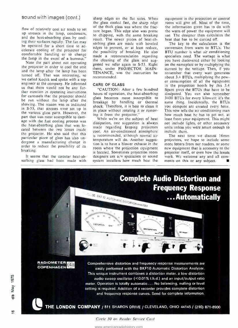
Complete Audio Distortion and Frequency Response
... Automatically
RADIOMETER _FM COPEN HAGEN
Comprehensive distortion and frequency response measurements are
easily performed with the BKF10 Automatic Distortion Analyzer. This unique instrument combines a distortion meter, a low distortion
audio sweep oscillator ( <0.01% t.h.d.) and an input /output ratio meter. Operation is totally automatic ... No balancing, nulling or level
setting is required. Addition of a recorder provides complete distortion and frequency response curves. Send for complete information.
L, THE LONDON COMPANY / 811 SHARON DRIVE / CLEVELAND, OHIO 44145 / (216) 871 -8900
Circle 30 on Reader Service Card
www.americanradiohistory.com

For over twenty -five years the Studer name has stood for excellence. Through the years Studer tape recorders have come to be recognized through- out the world as a standard of the broadcasting and recording industries. Studer's A80 /VU Recorder was developed for use in recording systems where only the highest quality is acceptable. The great care taken in the design, development and construction of the A80 /VU is reflected in its unusual reliability and stability. A superior transport combined with a
versatile electronics system and high -precision heads allow studio personnel to work surely. With the recorder a stable, predictable instrument, the ener- gies of the mixer and producer can be applied totally to the creative aspects of their work. For complete information contact ... WILLI STUDER AMERICA, INC., 3916 Broadway, Buffalo, New York 14227 -phone 716 681 -5450. (In Canada: WILLI STUDER CANADA, LTD., 416 423-2831)
WILLI
STUDER AMERICA
Circle 3/ on Reader Service Card
V
www.americanradiohistory.com

SLAVKO REBEC
Audio Booms in Discotheques Discotheques are vibrating again in major cities here and abroad. What's the sound like? Will it spread?
E DISCOTHEQUE scene is upon THE again, if you haven't noticed
it already. L.A.'s Rodney's, New Or- leans' Place Across the Street, Wash- ington's Pier 9, Chicago's Bistro, and New York's Club 82 have become the prototypes for hundreds of others like them both in North America and abroad.
When the phenomenon first started a year ago, it was called a minor fad by critics, destined to die before the year was out. Die it didn't. In fact, it went on to become a growing busi- ness.
Nationwide, discotheques are in- creasing at the rate of 10 percent a month. In recognition of this, record companies have created departments that deal exclusively with producing records geared to a dance formula. These records are distributed to dis- cotheque disk jockeys who monitor the public for reaction to the products even as they familiarize it to new sounds. Discotheques are rapidly be- coming a testing ground for records, second only to radio.
The popularity of this dance sound can be traced to the oversaturation of the youth market by R &B and hard - rock products. Evidence is seen in dip- ping sales and empty seats at concerts.
This new sound can best be de- scribed as a synchromeshed blend that is heavy on rhythm, brass and lush vocals. In some ways, it is a marriage of progressive rock and R &B, designed to move bodies, with a corresponding downgrading of the importance of lyrics. As one can imagine, the sound lends itself well to maximum treble and bass settings. Since sound pres- sure is one of the prime animating
Slavko Rebec hails from coo New York City's Greenwich Village
forces of the discotheque culture, the hardware that produces it merits some mention.
Another aspect of disco life is, of course, the unusual lighting effects used to set the mood. Several compa- nies manufacture special lighting sys- tems designed specifically for this pur- pose. One such company, Meteor Lighting Co., offers a sophisticated line including controllers, chasers, ro- tating prisms, strobes, etc. Adding color and action to the music intensi- fies the entire discotheque atmosphere.
SOUND SET -UP The composition of a disco sound
set -up is determined by two people: the owner and the audio dealer. The person who will run the equipment, the disc jockey, is rarely consulted. The owners of an about- to -be- opened discotheque in New York City may come to someone like Billy Bramble
Sound Workshop discole mk Ill
Bozak Model CMA -10 -2D Stereo Mixer /Preamplifier
of Atlantis Sound (one of the largest dealers in sound equipment on the East Coast) and tell him how much money they are willing to spend. "Usually it's around $5,000," says Billy who heads Atlantis' disco equip- ment department, "and as a rule, they leave the selection of the equipment to us."
In a sound package, priority (mo- ney -wise) is given to amps, pre -amps, speakers and the mixers. Savings, if any, are to be made in turntables, cartridges, earphones. and the like.
POPULAR EQUIPMENT Equipment used varies widely from
A ten channel, 1000- watt -per- channel, solid -state sequential switching device which is sound -triggered or operator - managed by an adjustable speed control.
-lo -- - 1
.. .., aua+cn two o
Stereo mixer pre -amp for discotheque use from Meteor Light and Sound.
www.americanradiohistory.com

expanded hi -fi systems to truly pro- fessional installations. Popular speak- ers are: Bose 901s (especially in tight places where space is unavailable for floor -mounting speakers), Altec, JBL, and Cerwin -Vega.
The most commonly seen amplifier is the Phase Linear 400, followed by the Phase Linear 700B, Crown, and McIntosh units.
Mixers range from custom -built mixers to the Sony MX -14 which, al- though not expressly designed for this purpose, is extremely popular. The Bozak model CMA -10 -2D is highly regarded and also extensively used in many clubs. GLI Industries, a New York based firm, has been selling a
simplified, less expensive version that has achieved popularity. We under- stand that several newer mixers are soon to appear on the market -Sound Workshop and Disko Mix -Master have plans, but no data are yet avail- able on these brands.
As for the equipment problems which disc jocks encounter, they nearly always boil down to manage- ment psychology regarding the sound equipment. In too many clubs, the equipment is looked upon as a neces- sary evil. Clientele relationship to sound quality and music is neither understood nor cared for. The disc
jock, who often is inexperienced, is responsible for both monitoring and maintaining the general health of the system.
Sometimes he has fairly inexpen- sive gear, which requires great care to keep it running. When he has to do this without the aid of spare parts and test equipment, one can appre- ciate his problems. In addition, the power is usually badly distributed, be- cause most customers want their sound at super -pressure level. A $5,000 economy package just doesn't have enough "guts" to handle the de- mand without a significant reduction in its life span.
Conditions would be more bear- able if some of these owners pro- vided an adequate repair budget and back -up system, but too often they don't. Caught in this crunch, most disc jocks regularly defect to more sound -conscious establishments as
soon as the grapevine indicates that an opportunity is about to open.
One such place is the Sound Ma- chine on New York's upper east side. They possess $25,000 worth of audio hardware, including nine Altec Voice - of- the -Theater speakers, each with its separate amplifier; two theater -type brass horns for the super lows; four JBL tweeters for the super highs; an
Altec Acousta -Voice equalizer; and a panel of vu meters monitoring the speakers. The makers of this pack- age, Rosner Custom Sound, of Long Island City, N.Y., gave disc jock Tony Palminteri (one of the found- ers of the disco craze phenomenon) plenty of power, range, and heavy - duty reliability for creating and blending sound.
NEW ACTIVITIES Discotheques are increasingly get-
ting into tape recorders, both for re- cycling the previous night's disco sounds (in a muted version) for day- time patrons, and as cassettes for car and home use.
The spreading discotheque craze has already spawned a mini discotheque kit for home and institutional applica- tion that is composed of: lights, dance records, and pictures put together as
a package by Deca Dance Systems of New York City. It is under study at Playboy, UA, ABC and Warner Broth- ers records.
Record companies are beginning to invest in and to back discotheques. The big money infusion that this im- plies should mean better and more reliable equipment for disc jocks and a great increase in the audiophile population.
eve Ves a a a by \
Sew in tbea
is tinte Kets°.1ust
look
t24 ß n o
°rtabte,
top q á hJ n'xin éns
Oves
. `atequatia inputs
with
plastic
,2 p
am a°
s áal á the same
high pe°r manc e
Ot c°utse t actiádbpOa tnd
atin 8
ñád 2 n
cOnnecto include
. Átis tot under
GALL US
Hupen Nove Ineorponded. Berkshire Industrial Park, Bethel. Connecticut 06801 Tel: (203) 744.6230. Telex: 969638
Rupert Nove Ineorpondod, Suite 616.
1800 N. Highland Ave.. Hollywood. California 90028 Tel: (213) 465 -4822
Rupert Nove of Canada. 1.1(1.. 2717 Hena Rand. Motion. Ontario L4T 3K1. Canada Tel: (416) 677 -6611
Rupert Nove & Company Lid.. Cambridge House. Melhnurn. Royston. Hert(nnlshim. SGB GAtt England. Tel: (0763) 60776
Rupert Nove Gaddi. 6100 Durmslndt Bismarckstmssc 114 West Germany. To:: (06151) 81764
Circle 32 on Reader Service Card
1 CO
www.americanradiohistory.com

o fV
The Great Gain Getter! The Universal Audio Model 560 Feedback Suppressor is a simple, compact, low -cost sound reinforcement tool for increasing gain before "howlback " in sound systems. Ideal for use in lecture halls, meeting rooms, schools and churches. Microphone or line -level input and output permits insertion between mike and amplifier or in line -level circuits. By centering the 560's four 1/6 octave notch filters on the system's most prominent resonant frequencies, gain can be increased up to 12 dB and intelligibility significantly improved. Each filter is tunable, 60 Hz to 6000 Hz in two ranges. Notch depth is adjustable to -20 dB.
The 560 can also improve more sophisticated broadband and /or 1/3 octave equalization methods by providing final "tweaking" of microphone proximity effects and troublesome residual resonances. So simple ... so inexpensive ... so, get one! UREI quality, of course.
UH "Instrumental in Audio"
11922 Valerio Street, No. Hollywood, California 91605 (213) 764 -1500 Exclusive export agent Gotham Export Corporation. New York
Circle 33 on Reader Service Card
CHEAP -but not dirty
60 Watts -4.0 or 8.0 Ohms minimum sine wave continuous average power from 20 Hz to 20 kHz with less than .05% total harmonic distortion.
Our power amplifiers are some of the best available. Our prices are some of the most reasonable available. You may not be famil- iar with our products since we sell only by direct mail and don't advertise a great deal.
We would like to send you our new 1975 catalog showing all of our fine audio pro- ducts and test report information on our famous "Tiger .01" shown above. You might be pleasantly surprised at how little clean power actually costs.
42207 Complete Kit 5 77.50 PPd
2%207 -A Assembled Amplifler S110.00 PPd
Sii Si Southwest Technical Products 219 W. Rhapsody San Antonio, Texas 78216
Circle 46 on Reader Service Card
you write it Many readers do not realize that they can also be writers for db. We are always seeking meaning- ful articles of any length. The subject matter can cover almost anything of interest and value to audio professionals.
You don't have to be an expe- rienced writer to be published. But you do need the ability to express your idea fully, with ade- quate detail and information. Our editors will polish the story for you. We suggest you first submit an outline so that we can work with you in the development of the article.
You also don't have to be an artist, we'll re -do all drawings. This means we do need sufficient detail in your rough drawing or schematic so that our artists will understand what you want.
It can be prestigious to be pub- lished and it can be profitable too. All articles accepted for pub- lication are purchased.
www.americanradiohistory.com

THE BEST OF db
HARRY F. OLSON
High -Quality Monitor Loudspeakers To achieve high-fidelity sound reproduction, you must understand and provide the required performance characteristics of a loudspeaker.
Reprinted from the December, 1967 issue of db.
WIDE frequency range, low distortion, uniform directivity and relatively high sound -power out- put loudspeakers are required for monitoring
in radio and television broadcasting, phonograph and sound motion -picture recording, and high -quality sound systems. The performance criteria of the sound reproducing systems
for these applications should satisfy the conditions required to provide high -fidelity sound reproduction. The purpose of this article is to define high -fidelity sound reproduction, describe the loudspeaker characteristics involved in achieving high -fidelity sound reproduction, give specifications of the loudspeaker performance characteristics and the means for providing the required performance characteristics in a
loudspeaker. Continued next page
In response to reader requests for technical data dealing with fundamental audio principles and practices, db Magazine is reprinting a number of outstanding articles from past issues, no longer available except on microfilm. Here is the first article in the series, called
The Best of db." ro
www.americanradiohistory.com

Performance Requirements For High -Fidelity Sound Reproduction
In the field of sound reproduction the term high fidelity is used to designate a quality of sound reproduction which provides a high order of realism.
To achieve this realism, that is high -fidelity sound repro- duction, three fundamental conditions must be satisfied as follows:
1. The frequency range must be such as to include with- out frequency discrimination all the audible components of the various sounds to be reproduced.
2. The volume range must be such as to permit noiseless and distortionless reproduction of the entire range of intensity associated with the sounds.
3. The subjective aspects involving psycho-acoustic effects must be used in an appropriate manner in order to obtain a close artistic resemblance of the original rendition: these include loudness and dynamics, noise, auditory perspective and reverberation.
The elements of a sound reproducing system must exhibit such an order of excellence of performance so that the above conditions are satisfied if high -fidelity sound repro- duction standards are to be met. The loudspeaker is one of the important elements of the sound reproducing chain. Its characteristics involved in achieving superior performance are: frequency response, directivity, non -linear distortion, transient response, impedance, efficiency, and maximum sound -power output.
Frequency Response A loudspeaker's frequency response is the sound pressure
on the axis as a function of the frequency. The loudspeaker should provide uniform response over
the frequency range from 30 to 15,000 Hz. For most high -
quality applications the response should be contained within the limits depicted in fig. 1. In general, there is no problem in achieving this performance today in a high -quality loud- speaker. The procedure is to divide the frequency range
into two or more parts and employ separate mechanisms for each range. This expedient makes it possible to achieve uniform response in both direct radiator and horn loud- speakers. However, some care must be exercised in the geometric configuration of the mechanisms to avoid deleteri-
5
-15 30 100 1000 8000 15000
FREQUENCY IN HZ
Fig. 1. A high -quality loudspeaker system should fall between these upper and lower limits of frequency response.
ous phase effects in overlap frequency regions due to a
large physical separation compared to the wavelength be-
tween the mechanisms.
Directivity
The directional characteristic of a loudspeaker is its re-
sponse as a function of the angle with respect to some reference axis of the system.
The directional patterns are usually depicted in polar coordinates. If the directivity pattern varies with frequency, frequency discrimination will occur for observation and
listening points removed from the axis. Uniform directivity is particularly important in stereophonic sound reproduction in order to provide realistic auditory perspective.
Limits on the directivity pattern of a loudspeaker over the response range of 30 to 15,000 Hz are depicted in fig. 2. The polar curves should fall within the amplitude limits
90°
45°
Fig. 2. The directivity pattern of a good speaker system should fall between these extremes over the 30 to 15,000 Hz range.
shown for an angle of at least 45 ". For really high quality, the polar curves should fall within the amplitude limits shown for an angle of 90 °.
The directivity pattern of a direct radiator loudspeaker can be controlled by the shape of the cone. The directivity pattern of horn loudspeakers can be controlled by the
shape and design of the horn. An additional powerful means which can be employed to control the directivity pattern over the wide frequency range is the idea of divid- ing the frequency range into two or more sections. Addi- tional expedients which may be employed to control the
directivity are the use of diffractors, reflectors and acoustic lens.
Non -Linear Distortion The non -linear distortion frequency characteristic of a
loudspeaker is the total non -linear distortion as a function of the frequency.
The major result of non -linearity in the elements of the
vibrating system of a direct radiator loudspeaker is the
production of harmonics and subharmonics. Two major contributors to non -linear distortion in dynamic loud- speaker mechanisms are the driving and suspension ele-
ments. These elements are constant for small and moderate amplitudes but depart from constancy for large excursions of the cone or diaphragm. In the low- frequency range
the amplitude of the cone in the direct- radiator loud- speaker must be inversely proportional to the square of the
frequency and the amplitude of the diaphragm in the
horn loudspeaker must be inversely proportional to the
frequency in order to maintain constant output with respect
www.americanradiohistory.com
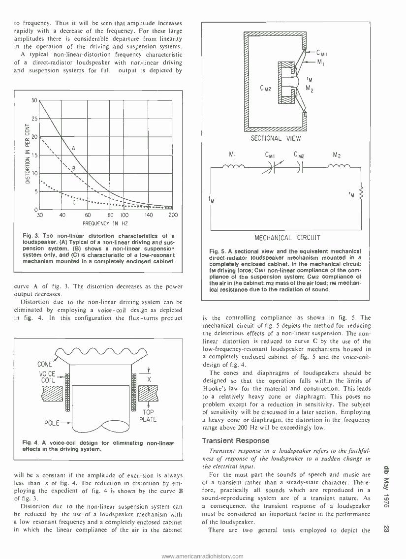
to frequency. Thus it will be seen that amplitude increases rapidly with a decrease of the frequency. For these large amplitudes there is considerable departure from linearity in the operation of the driving and suspension systems.
A typical non -linear -distortion frequency characteristic of a direct -radiator loudspeaker with non -linear driving and suspension systems for full output is depicted by
30
5
0
, .
. B
r,
C , :7 riv« -
30 40 60 80 100
FREQUENCY IN HZ
140 200
Fig. 3. The non -linear distortion characteristics of a loudspeaker. (A) Typical of a non -linear driving and sus- pension system, (B) shows a non -linear suspension system only, and (C) is characteristic of a low- resonant mechanism mounted in a completely enclosed cabinet.
curve A of fig. 3. The distortion decreases as the power output decreases.
Distortion due to the non -linear driving system can be
eliminated by employing a voice -coil design as depicted in fig. 4. In this configuration the flux -turns product
CONE
VOICE COIL
Fig. 4. A voice -coil design for eliminating non -linear effects in the driving system.
will be a constant if the amplitude of excursion is always less than x of fig. 4. The reduction in distortion by em- ploying the expedient of fig. 4 is shown by the curve B of fig. 3.
Distortion due to the non -linear suspension system can be reduced by the use of a loudspeaker mechanism with a low resonant frequency and a completely enclosed cabinet in which the linear compliance of the air in the cabinet
SECTIONAL VIEW
Mi Cm] C M2
fm
CMI
M1
M2
rM
MECHANICAL CIRCUIT
Fig. 5. A sectional view and the equivalent mechanical direct -radiator loudspeaker mechanism mounted in a
completely enclosed cabinet. In the mechanical circuit: fm driving force; CMt non -linear compliance of the com- pliance of the suspension system; CM2 compliance of the air in the cabinet; m2 mass of the air load; rM mechan- ical resistance due to the radiation of sound.
is the controlling compliance as shown in fig. 5. The mechanical circuit of fig. 5 depicts the method for reducing the deleterious effects of a non -linear suspension. The non- linear distortion is reduced to curve C by the use of the low- frequency- resonant loudspeaker mechanisms housed in a completely enclosed cabinet of fig. 5 and the voice -coil- design of fig. 4.
The cones and diaphragms of loudspeakers should be
designed so that the operation falls within the limits of Hooke's law for the material and construction. This leads
to a relatively heavy cone or diaphragm. This poses no problem except for a reduction in sensitivity. The subject of sensitivity will be discussed in a later section. Employing a heavy cone or diaphragm, the distortion in the frequency range above 200 Hz will be exceedingly low.
Transient Response Transient response in a loudspeaker refers to the faithful-
ness of response of the loudspeaker to a sudden change in the electrical input.
For the most part the sounds of speech and music are
of a transient rather than a steady -state character. There- fore, practically all sounds which are reproduced in a
sound- reproducing system are of a transient nature. As a consequence, the transient response of a loudspeaker must be considered an important factor in the performance of the loudspeaker.
There are two general tests employed to depict the w
www.americanradiohistory.com

N
transient response of a loudspeaker: the square wave and tone burst.
Figure 6 shows the amplitude response of a loudspeaker and tone -burst response. The tone -burst response is quite faithful in the smooth part of the amplitude range. How- ever, there is considerable deviation of the tone -burst response at the peak and the dip. In general, in a properly designed loudspeaker, if the response of the loudspeaker is smooth the transient response will be good.
15
200 400 600 80Q 1000 2000
FREQUENCY IN HZ
400 HZ
1
11
850 HZ 1200 HZ
ELECTRICAL INPUT
SOUND OUTPUT
Fig. 6. The relationship of the frequency- response char- acteristic and the tone -burst response of the same loud- speaker is shown at 400, 850, and 1200 Hz.
mpedance The frequency impedance characteristic is the electrical
impedance of the loudspeaker as a function of frequency. In the dynamic loudspeaker the variation with frequency
is relatively small and there is normally no problem on
the transfer of power from the amplifier to the loudspeaker.
Efficiency The efficiency of a loudspeaker is the ratio of the sound -
power output to electrical -power input. For monitoring applications the low efficiency exhibited
by most monitoring loudspeakers is of little concern be-
cause the maximum sound levels needed can be obtained with relatively modest amplifiers. However, for large - scale sound reproduction, as for example, sound rein- forcing systems in large auditoriums, efficiency is a con- sideration if the amplifier requirements are not to become ridiculously large.
Maximum Sound Power Output The maximum sound power output of a loudspeaker
determines the level which the loudspeaker can deliver under a particular condition.
For monitoring purposes the loudspeaker should be
capable of delivering a level of at least 100 dB. The sound - power output required as a function of the room volume is
shown in fig. 7. An alternate specification is 1 acoustic watt per 1000 square feet of area to be covered.
100
m 1-
10 z
g Ú Ìn
01
Fig. 100 Is
/
lid Fr 103 104 103 06
VOLUME IN CUBIC FEET
7. The acoustical power required to produce a
dB level in monitoring room, studio, or auditorium, shown as a function of the room's cubic volume.
These, in sum, are the performance characteristics used
to determine high -quality loudspeakers for use in professional monitoring and sound systems. In general, this data repre- sents the state of the loudspeaker art at this time.
Additional Comments The loudspeakers used for professional sound applications
are practically all of the dynamic type mechanism operating either as a direct radiator or horn driver. The main reasons
for this state of affairs are as follows: I. The mechanisms are relatively simple. 2. The mechanisms are comparatively easy to build. 3. The mechanisms are rugged and outlast some of the
other electronic components. 4. The mechanisms are relatively reliable.
5. Very good performance characteristics can be obtained if there are no unreasonable limits on cost.
Loudspeakers are often accused of being the weakest
link in the sound reproducing chain. The question arises,
namely, if the performance of a loudspeaker is so terrible, why is it possible by means of subjective tests employing a loudspeaker to demonstrate a minor improvement in
one of the other elements of the sound- reproducing system?
As a specific example, why is it possible by means of listening tests to detect a difference in the performance of two power amplifiers of different designs, both flat to within a decibel from 20 to 20,000 Hz, both with distortion of a small fraction of a per cent up to 20 watts, and both with excellent transient response?
The answer is that the performance of a high -quality loudspeaker is pretty good for the various characteristics in
the amplitude and frequency ranges that count.
www.americanradiohistory.com

o 0 new pvoducts&seniices SOLID STATE POWER AMPLIFIER
Reliability problems encountered in drive -in theaters spurred the develop- ment of model 1590B /TH solid state power amplifier. The amplifier is rated at 200 watts at less than one percent total harmonic distortion from 50Hz to 12kHz. Strapped for 8 ohms, 35 volt operation, it has easily accessible strapping options for 16 ohm, 70 volt operation. The unit features silicon solid -state circuitry input connections for high- impedance devices and for 600 -ohm or 15,000 -ohm balanced in- puts, and fail -safe protection for out- put transistors. 1590B /TH is capable of operation from a 120V or 240V a.c. source or a negative grounded
28V d.c. source. A trickle charging current maintains battery charge when the amplifier is operated in the a.c. mode. 1590B /TH is designed for rack -mounted use, occupying six units of vertical rack space. Mfr: Altec Corp. Circle 50 on Reader Service Card
THERMAL SPOT TESTER
'II- A small blower heater with an ex-
tension tube, the Thermal Spot is an electronic circuit fault detector. As it warms up to 260 degrees F. directed at a single spot, it heats up individual capacitors and transistors to find mal- functions that only appear when cir- cuits are warmed. It can also he used
to spot dry epoxies or tuners and other components after cleaning. Mfr: Wahl Clipper Corp. Circle 51 on Reader Service Card
TAPE CARTRIDGE MACHINES
Series 2000 Spotmaster tape car- tridge machines have a claimed noise figure of over 57 dB and under 80 millisecond start /stop time. Features include balanced transformer output. 1000 Hz cue, ISO Hz cue and provi- sion for remote control and telephone interface. Separate front panel plug - in modules are used to implement re- cord and audition functions. Mir: Broadcast Electronics, Inc. Price: Mono playback: $465
Mono record / playback: $675 Circle 52 on Reader Service Card
The Auto Hanger: first of its kind The first commercially -made studio product using state -of- the -art charge -coupled, bucket
brigade technology. Reel flanging at the push of a switch and the turn of a knob. .Comb filter effects heretofore impossible without two solid tapedecks, a mixing console, and a careful engineer are now possible ... at a clearly affordable price.
Implementing state -of- the -art technology in affordable packaging is our foremost objective in product development. Our R & D teams are committed to supplying the audio engineer with products combining imagination, technology, cost -effectiveness.... Innovation.
MXR Innovations 277 North Goodman St.
Rochester, New York 14607
Circle 38 on Reader Service Card N N
www.americanradiohistory.com

IT111 , .....,.......,....,..........,,,.,.......,,,., ,,,,,,NO,N,,,,
THE WORLD'S LARGEST ELECTRONIC EVERYTHING HOUSE
FOR THE PROFESSIONAL The biggest "in- stock" inventory of professional audio /video
equipment, parts and accessories -anywhere. The Everything House has everything for the
professional ... broadcast, audio, video, sound reinforcement and hi -fi stereo components.
Quality products from over 200 leading manufacturers *.. what you want, when you want it!
Consult Martin's specialists about installation ... service ... systems design ... and sales for all your audio /video needs.
-- 11,T Such as: AKG, Altec, Ampex, Crown, DBX, Dolby,
J. B. Lansing. 3M, Shure. Neumann, Sony, Scully, McIntosh, Urei
Call or write for a free catalog
un 320 West 46th Street, N.Y.C. 10036 in
l (212) 541 -5900 Audio /Video Circle 41 on Reader Service Card
Clean up your church .. .
school, club. or business sound system with the new Electro -Voice LR4B Line Radiator.'" The new Electro -Voice LR4B Line Radi- ator squarely meets the challenges of critical listeners and demanding users. You get wide -range, smooth re- sponse that makes everyone sound good ... voice or music. And the coverage pattern from our unique multi- faceted design helps reduce feedback compared to less so- phisticated column speakers. This means more useful gain is available when inexperienced performers get off -mike or don't speak up.
The LR4B is just one of the useful tools only E -V distrib- utors have available for the thoughtful sound man. Ask your rep or contact us at the factory for full details.
Elecl`rol/oiceNc ELECTRO- VOICE, INC., Dept. 556-BD 686 Cecil Street, Buchanan, Michigan 49107
Circle 42 on Reader Service Card
a pul0on CarT1pQY
new products & services (cont.)
F.M. STEREO TUNER
Noise and distortion that have mixed with the signal during its trans- mission to the receiver can be reduced to below audible level by Accuphase T -101, according to the manufacturer. The unit's design has been concen- trated on sharp selectivity for recep- tion that requires critical separation and stresses lowest distortion for re- ception where there is no noise elimi- nation problem. Multipath effects on input signal quality can be checked by an independent multipath meter. A signal strength meter and a center tuning meter are also provided. The front end is equipped with a fre- quency 4 -gang variable capacitator, dual gate mos fet transistor circuitry, and local oscillator isolated by a buf- fer circuit. Performance includes wide dynamic range input, spurious signal rejection over 100dB and image re- jection over 80 dB. Features include a variable selectivity i.f. circuit, a wide -band detector circuit, stereo -only switch, muting switch, and stereo noise filter. A tape deck can be con- nected directly to the fixed level out- put and an amplifier can be connected to the variable output. Mfr: TEAC Corp. Price: $450.00. Circle 53 on Reader Service Card
POLYURETHANE POTTING COMPOUND
Sealing and potting compond ZT- POLY, with a gel time of ten minutes at room temperature and a tensile strength of 1735 psi and hardness of 55/55 is recommended for encapsu- lating wire or cable splices, etc. Pack- aged in 6, 8, and 20 ounce cartridges, the two -part compound is mixed with a pumping rod and dispensed by the rod as a lever. Available also in bulk. Mfr: Zippertubing Co. Circle 54 on Reader Service Card
www.americanradiohistory.com

AUDIO CONSOLE COMPONENT
0 o a o a a ma.
P P G I A P P O P
Eight -channel rack -mountable mix- er /preamplifier model SR101 console may be custom -installed in a desk or console, measures 121/4 x 19 x 63/4
inches. The unit accepts up to eight low impedance microphones, each with individual controls for volume, reverberation, high- and low- frequency equalization, and input attenuation. Switchable inputs on channels 7 and 8 also accept auxiliary high -level sig- nals or high impedance mics. Model SR101 provides simultaneous program and monitor outputs, each controlled by its own master volume control. Program output has a 600 -ohm bal- anced, line level output. The monitor output has a 600 -ohm unbalanced, line level output and an eight -ohm output for mono or stereo head- phones. Other features include: dual link jacks; master and individual linear - motion feedback -type channel volume
controls; master reverb in /out control; individual attenuators for each chan- nel; four anti -feedback switches; light- ed vu meter; kHz tone oscillator with its own volume control. Mir: Shure Bros. Circle 55 on Reader Service Card
STEREO /PIANO AUDIO PICKUP
Two transducers permit FS -200 to pick up two instruments or to offer improved pickup on piano. The de- vice, which attaches with special inert adhesive wax, contains a preamp with an LRN -69 power supply, outputs for stereo and /or mixed mono, and built - in variable low frequency rolloffs for each channel, which can roll off the lows at 6 dB octave from approxi- mately 30 to 300 Hz. FS -200 plugs into an a.c. outlet. Although designed primarily for piano, it can be used with other instruments. Mir: FRAP Price: $650.00 Circle 56 on Reader Service Card
WE HAVE ALL THE RIGHT CONNECTIONS.
A "simple" microphone extension cable isn't so simple. Not if it's going to match today's phase ac- curacy and continuity requirements!
At Gotham, we start with double RF shielded, 3- conductor cables made to Neumann's tight specifica- tions. And we attach Switchcraft "Q -G" (XLR compatible) connectors with a special technique, so the connector shell is grounded.
Our price? Practically what you'd pay for cable and plugs alone. Twenty -five feet, $9.60. Fifty feet, $14.96. One hundred feet, $26.48. In small quantities. (12 or more.)
Order through your Neumann Microphone Dealer. Or from Gotham directly.
GOT HAM AUDIO CORPORATION
741 Washington Street, New York, NY 10014 (Tel: 212- 741 -7411)
1710 N. La Brea Ave,. Hollywood, CA 90046 (Tel: 213 -874 -4444)
Limited only by your imagination you had a general purpose limiter with fast response, bridging input, low impedance output, instan-
3ous LED G.R. readout, and adjustable threshold, output and release time, attractively priced, im- -le the many uses you could put it to. Think of all the transmitters that get over -modulated, all the line - that get over -driven, all of the tapes that get saturated, all the peaks that get clipped, all the mics that blasted The MXR Mini Limiter is very general purpose in its applications, compact in design, satile in implementation, stereo strappable.... and gloriously affordable.
lany simple problems -a simple solution. So much in keeping with MXR design objectives.
MXR Innovations 277 North Goodman St. /Rochester, New York 14607
.`j _Ì ,
t. 1I ~ +=
=i t * * ai: a i .. . '
Circle 39 on Reader Service Card
www.americanradiohistory.com

CO N
AUDIOWAVES The perfect beginning. n n i n g
Sound decisions start with a
N g microphone. That's why RCA offers a complete line.
There are velocity, pressure and dynamic mikes to choose from. And when you want particularly faithful reproduction of speech or music, RCA ribbon microphones, with their excellent bass response, are what you need.
See your RCA representative. It could be the perfect beginning of a sound relationship. RCA Broad- cast Systems, Camden, N.J. 08102.
RCA Microphones
Microphones Consoles Tape and Transcription Equipment Automation Systems Amplifiers and Speakers
Circle 43 on Reader Service Card
state -of- the -heart YOU'LL LOVE ITS FEATURES!
PUNTA REMOTE CONTROL INOVONICS MODEL 355
DUAL -CHANNEL TAPE ELECTRONICS: $1320 This high.performance package is ideal for criginal installations or for upgrading existing systems.
Features include: E Conservative design criteria and distortion.reducing circuitry to assure highest Quality recordings. D Capability for remote control of all recording and monitor
functions. O Solidslate switching to eliminate punch -in and contact noise. Individual SYNC and reproduce amplifiers for optimum SYNC performance.
Versatile 3-speed E7 for all NAB and IEC standards. Chec< out the Model 355. You'll love its features and performance!
0 Call or write today.
1 INCORPORATED INOVONICS
1630 Dell Ave., Campbell, CA 95008
Phone C08 314 8300
Circle 44 on Reader Service Card
new products & services (cont.)
MINIATURE CAR SPEAKER SYSTEM
Designed for confined areas such as
vans, where only d.c. is available, mod- el 2001 miniaturizes some high -power features. It contains a 4 -inch diameter precision woofer and a soft -dome tweeter. A total of 160W of sine wave power is provided by four indepen- dent amplifiers, coupled with elec- tronic crossover networks, equalizers, and opto- electronic limiters. The high power level is generated with the help of a new d.c. /d.c. switching converter operating at 25kHz. The complete system consists of two speaker units 67/e x 41/4 x 4 inches, and a power supply amplifier box measuring 35/s x 10 x 93/4 inches. Mir: Analog & Digital Systems Circle 57 on Reader Service Card
INDICATOR METERS
Two new units have been added to this manufacturer's line of vertical scale and arc -scale meters. PK -100 has the same amplifier electronics as model PK -14/ I6, which converts con- ventional vu meters into peak level monitoring instruments. The circuit board module features simple attach- ment to existing meter terminals and mating connector, shallow behind - meter profile, accessible adjustments for electronic change of integration time, fall -back and tracking. Model PKM -400 has four independent chan- nels of led, indicating level monitor- ing. Alternate mode PK -16 is utilized in a self -powered, small portable con- sole top package. It features XLR in- put connectors and a built -in display brightness control. Mir: Quad /Eight Electronics Circle 58 an Reader Service Card
www.americanradiohistory.com

OMNIPRESSOR
New features announced by the manufacturer of model 2830 omni- pressor includes separate control of attack and release times; attack varies from 100 microseconds to 100 milli- seconds and releases from 1 millisec- ond to 1 second, both continuously adjustable and calibrated. Model 2830's leds show instantaneous limit- ing which the meter cannot follow. The unit also has parabolically cali- brated function control, allowing com- pression /expansion ratio adjustment without reference to meters. Input threshold control is adjustable over -25 to +15 dBm range, fully cali- brated. There is complete control of compression and expansion ratio, in- cluding infinite compression, dynamic reversal, and selection of control range up to 60 dB. The device can be used as a fast limiter as well as a special effects and standard compressor. Mfr: Eventide Clockworks, Inc. Price: $600.00. Circle 59 on Reader .Service Card
SPEAKER SYSTEM
Afte Model 5 is a medium efficiency sys-
tem, designed for use with amplifiers of at least 30W rms per channel, up to 250W rms per channel. Model 5 is
capable of handling musical input of 35 -45V (320- 412W). It uses an AGC 3 fuse; the filter network contains a
fuse holder, as well as a spare fuse block. Frequency response is 32- 20,000 Hz 2dB. Impedance is 6
ohms. An optional asymetrical pede- stal is available to hold the 56 -pound weight of the speaker. Mir: Rectilinear Research Corp. Price: $300.00.
Base: $59.00 per pair. Circle 60 on Reader Service Card
We takethewait out of erasing lots of tape
alk
New Model 70 cleanly erases any 7" reel, cartridge, or cassette in
one pass over the continuous belt. Your tapes will be as clean
as new in 4 seconds. For audio, video, and data tapes.
GARNER INDUSTRIES
Circle 45 eue Reader Service Card
Phase in your studio The MXR Auto Phaser can convert 10.5 square inches of unused board space
into the most useful musical effect known to the modern recording engineer today, at an uncompromisingly low price. Internally contained sweep oscillator, power regula- tion and logarithmic amplifier teamed with external voltage control capability, and a dynamic range in excess of 100 decibels, make the Auto Phaser without par in the industry.
Phasing is rapidly becoming as commonplace today as reverberation. So very often many channels require individual simultaneous phasing effects, stereo enhancement and frequency modulation, until now unattractive due to cost and space limitations.- Freeing the creative imagination through technological innovation-
MXR Innovations Professional Products Group 277 North Goodman St. /Rochester, New York 14607
Circle 40 on Reader Service Card
www.americanradiohistory.com
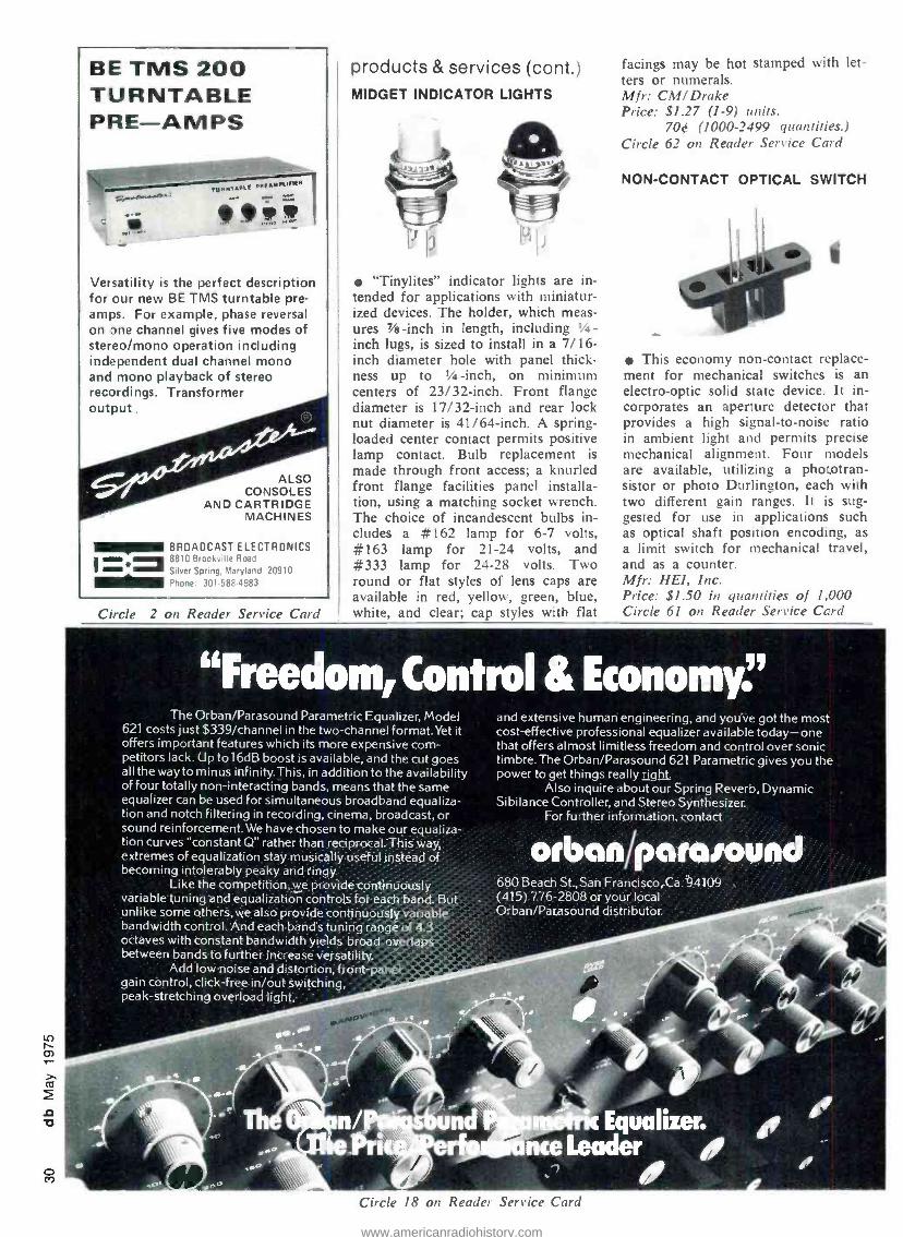
o CO
BE TMS 200 TURNTABLE PRE -AMPS
TURNTABLE e.e.eL,.,..
9 10!J'*
Versatility is the perfect description for our new BE TMS turntable pre - amps. For example, phase reversal on one channel gives five modes of stereo /mono operation including independent dual channel mono and mono playback of stereo recordings. Transformer output .
ALSO CONSOLES
AND CARTRIDGE MACHINES
BROADCAST ELECTRONICS - 8810 Brookville Road
Silver Spring, Maryland 20910
Phone: 301 -588-4983
Circle 2 on Reader Service Card
products & services (cont.) MIDGET INDICATOR LIGHTS
"Tinylites indicator lights are in- tended for applications with miniatur- ized devices. The holder, which meas- ures 7/e -inch in length, including 1/4-
inch lugs, is sized to install in a 7/16- inch diameter hole with panel thick- ness up to 1/4-inch, on minimum centers of 23/32 -inch. Front flange diameter is 17/32 -inch and rear lock nut diameter is 41/64 -inch. A spring - loaded center contact permits positive lamp contact. Bulb replacement is made through front access; a knurled front flange facilities panel installa- tion, using a matching socket wrench. The choice of incandescent bulbs in- cludes a #162 lamp for 6 -7 volts, #163 lamp for 21 -24 volts, and #333 lamp for 24 -28 volts. Two round or flat styles of lens caps are available in red, yellow, green, blue, white, and clear; cap styles with flat
facings may be hot stamped with let- ters or numerals. Mfr: CM/ Drake Price: $1.27 (1 -9) units.
70¢ (1000 -2499 quantities.) Circle 62 on Reader Service Card
NON -CONTACT OPTICAL SWITCH
f
This economy non -contact replace- ment for mechanical switches is an electro -optic solid state device. It in- corporates an aperture detector that provides a high signal -to -noise ratio in ambient light and permits precise mechanical alignment. Four models are available, utilizing a phototran- sistor or photo Durlington, each with two different gain ranges. It is sug- gested for use in applications such as optical shaft position encoding, as a limit switch for mechanical travel, and as a counter. Mfr: HEI, Inc. Price: $1.50 in quantities of 1,000 Circle 61 on Reader Service Card
"Freedom, Control &Economyr The Orban /Parasound Parametric Equalizer, Model
621 costs just $339 /channel in the two-channel format.Yet it offers important features which its more expensive com- petitors lack. Lip to 16dB boost is available, and the cut goes all the way to minus infinity.This, in addition to the availability of four totally non -interacting bands, means that the same equalizer can be used for simultaneous broadband equaliza- tion and notch filtering in recording, cinema, broadcast, or sound reinforcement. We have chosen to make our equaliza- tion curves "constant Q" rather than recipr al: This way, extremes of equalization stay musically ust fikinstead of becoming intolerably peaky and ringy.
Like the competition, we provide .continuously variable tuning and equalization controls for each band. But -
unlike some others,we also provide continuously variable bandwidth control And each band's tuning range of 4.3 ,,6, octaves with constant bandwidth yields broad overlaps between bands to further intrease versatility.
Add low noise and distortion; front -panel gain control, click-free .in /6dtwitching, peak -stretching overload light-.
and extensive human engineering, and you've got the most cost -effective professional equalizer available today -one that offers almost limitless freedom and control over sonic timbre.The Orban /Parasound 621 Parametric gives you the power to get things really right.
Also inquire about our Spring Reverb, Dynamic Sibilance Controller, and Stereo Synthesizer.
For further information, contact
680 Beach St., San Francisco, Ca. 94109 . .
(415).776 -2808 or your local Orban/Parasound distributor.
Circle 18 on Reader Service Card
www.americanradiohistory.com

HIGH POWER AMPLIFIER
Monaural, single- channel amplifier model M -600 has been designed to meet the demands of high power am- plification. M -600 amplifier signals from d.c. to 20kHz and provides 70 volt unbalanced line output at 600 watts of continuous power into 8
ohms and 1,000 watts into 4 ohms, indefinitely. The amplifier contains built -in cooling, which permits con- tinuous full power operation. A two - speed sans shifts to high speed if heat sinks exceed 140 degrees F., the am- plifier shuts down to standby mode if the sink temperature exceeds 160 degrees F. and then automatically re- activates when temperature drops down below 160 degrees F. A change- able, plug -in input board enables the unit to drive any type of input load, including a pure reactance, without adverse effects. Modifications to the board can be used to add filtering, preamplification, mixing, and constant current sensing. An output bridge cir- cuit is designed to permit extremely high power levels to be safely sus- tained for ultra high power applica- tions. It is possible to couple two M- 600s together through a socket at the back of each amplifier. Mfr: Crown International Circle 63 on Reader Service Card
FOUR -CHANNEL LIMITERS
This modular item fits into a double module space in the manufacturer's model 10 console. Designated L -100T and L -150T, the limiters use leds to give rapid response in limiting thresh- old indication. Each channel of the L -150T limiter /compressor has con- trols for input level, output level, at- tack and release times, and compres- sion ratio. In addition to giving pro-
tection from transient overload, the unit allows the shaping of dynamics. Through the use of the attack and re- lease controls, the engineer may allow some transients to pass unlimited to retain dramatic impact and still com- press to give maximum sound power to the material. L -100T, the basic 4- channel unit, has fixed rather than variable compression, attack, and re- lease times. It provides high ratio peak limiting aimed at leaving the hi:lk of the program material unaffected and protecting from transient overload sat- uration. Mir: Sound Genesis Circle 64 on Reader Service Card
TURNTABLE PREAMPS
High sensitivity, inaudible distor- tion and RFI suppression are claimed by the manufacturer of E series turn- able preamps. MP -8E (mono) and
SP -8E (stereo /dual mono) provide at least +4dBm -out with as little as
500uV -in at 1kHz. Adjustments are provided to enable the preamps to ac- cept up to 100mV -in before distorting. The units have rear terminals for re- motely switching to one of three modes of operation: RIAA response ±dB, scratch filter, or brilliance boost. The series features balanced 600 ohm out- puts capable of at least +21dBm -out, signal /noise ratio of -77dB, distor- tion of less than 0.05 percent and greater than 70dB channel separation. The units contain their own internal power supply and may be either table- top or bracket mounted. Mfr: Ramko Research Price: SP-8E: $137.00
MP -8E: $86.00. Circle 65 on Reader Service Card
-36 types of empty tape reels
Q1 \ \and boxes
D 17for hi -speed duplicating audio spots - tv spots
IMMEDIATE SHIPMENT FROM MANUFACTURER'S STOCK
GET CATALOG PD 175
Polylive CORP. 312/298 -5300
1241 Rand Rd. DesPlaines, IL 60016
Circle 49 on Reader Service Card
'qt.*
t :i.
j , ::'i'-::i:::::
;Tel ::a ipg; ...
. t ̂- ~ t'«T-^ri r 7Z.-:_ =
1 - ,*` ...
Q r Ask anyone.
w
www.americanradiohistory.com

DOUGLAS R. KAYE
Motion Picture Sync Systems
The need to synchronize sight and sound has generated ingenious applications of mechanics and electronics.
Figure 1. Single system.
SHAFT
MAGNETIC FILM RECORDER AUDIO
Figure 2. Mechanical interlock.
Douglas Kaye is associated with Du Art Film Labs, Inc. ("I of New York City.
EVER SINCE sound was added to motion pictures, filmmakers have been challenged by the neces- sity of keeping picture and sound accurately syn- chronized. There are basically three systems for
recording synchronous sound, either on location or in the studio.
1. Single System. The sound is recorded directly on the original camera film, either as an optical sound track or on film which has been magnetically stripped by the manu- facturer. Magnetic 16 mm single system is common in newsreel and documentary filming.
2. Double System (Sprocketed). This system was used primarily in studio filming, but is now rarely seen except in special circumstances. It involves the use of a recorder designed to operate with 16 mm sprocketed magnetic film running at 36 f.p.m., 35 mm magnetic film at 90 f.p.m., or 17.5 mm magnetic film at 45 f.p.m.
3. Double System (Non -Sprocketed). This relatively recent innovation, often called the "pilotone" system, has rapidly replaced the first two systems in nearly all cases except news production. Audio is recorded on standard tape in the conventional manner. But instead of using perforation holes, a "sync pulse" representing variations of camera speed is recorded on either a separate track, as
in the case of multi -track sync recording, or superimposed over the audio track area, as in the Rangertone, Perfectone or Neopilot systems. This sync pulse track can also carry information for slates (start marks) and scene identi- fication.
SINGLE SYSTEM Single system sound (FIGURE 1) is, by its very nature,
self- synchronizing, providing the camera is properly threaded. As currently used in 16 mm filmmaking, the film passes either an optical film gate or a magnetic recording head exactly 26 frames after it passes through the photo- graphic aperture. In magnetic newsreel cameras there is also a playback head located one or two frames after the record head to allow the recordist to monitor the record- ing properly. To play back an optical single system re- cording, one must wait until the film has been processed.
www.americanradiohistory.com

FILM RECORDER
POWER
-6 AUDIO
Figure 3. A.C. line sync.
1/4 INCH RECORDER
SYNC INPUT
Figure 4 -A. Rangertone System.
DOUBLE SYSTEM (SPROCKETED) The simplest double system sound equipment requires a
direct mechanical connection between the camera and a sprocketed magnetic film recorder (FIGURE 2). As the camera's motor advances the film one frame, a shaft con- necting the camera and recorder rotates and advances the recorder's sprocket by one frame. By connecting the shaft to the camera's motor rather than to the intermittent cam- era movement and by employing the appropriate reduction gears, the shaft's rotation will be continuous, which is nec- essary for flutter -free recording. If the camera speed va- ries, so does the recorder speed, and frame -by -frame syn- chronization is therefore maintained.
Since it is quite impractical to keep a bulky recorder within a few inches of the camera at all times (especially during hand -held shots) an electrical counterpart to the direct drive was invented. If an a.c. synchronous motor is operated within the proper load and voltage parameters, its rotation will precisely follow the frequency variations of the supply voltage as long as the variations are neither too sudden nor too severe. With similar synchronous mo- tors on both the camera and the sprocketed film recorder. each machine will be "locked -in" to the sync of the power line (FIGURE 3). If both machines are connected to the same a.c. source, they will run in perfect synchronization. To label the start of each take (the recorder and camera drop out of sync the moment either is switched off of the a.c. line), a slate is employed. The first picture frame in which the editor sees the slate's clapstick fully closed will correspond to the frame in which the clap is heard on the sound track. This requires that both the camera and the recorder are running at speed and are locked -in to the a.c. line before the slate is clapped.
DOUBLE SYSTEM (NON -SPROCKETED) With the invention of high -quality I _: -in. portable tape
recorders, designers searched for an electronic system to eliminate the bulky and expensive sprocketed magnetic film recording systems.
The original Rangertone concept (FIGURE 4) involved running the camera from the a.c. mains and recording that
1111111111111 MT - p AUDIO SYNC
87-
Figure 4 -B. Rangertone head and track.
AUDIO
m
SYNC
Figure 5. Pertectone head and track.
m 1.1
Ilillllll11111I AUDIO SYNC
Figure 6. Neopilot head and track.
same a.c. signal (at a much lower voltage) on the 1/4-in. tape, parallel to the audio signal. This system resulted in a 1 /4 -in. tape with invisible magnetic "sprocket holes" re- corded along the center of the tape in a special sync pulse track. As the camera speed varied due to fluctuations in the a.c. line frequency, the distance between corresponding sync pulses varied accordingly.
This system not only accounted for changes in camera operation, but also for any effects of uneven recorder op- eration or tape- stretching. Instead of recording these 60- Hz pulses on a separate track alongside the audio track, the Rangertone recorders used a separate sync pulse head which was rotated 87 degrees out of alignment with re- spect to the other heads. The intention of having the sync head so drastically out of alignment was to avoid repro- ducing the 60 -Hz signal along with the audio track by a standard full -track playback head. But it was not entirely successful.
The Perfectone system (FIGURE 5) was an improvement over the Rangertone system. Two heads recorded identical sync pulses along opposite edges of the tape. However, they were staggered by the necessary distance so that a 60 -Hz signal recorded by both heads at a tape speed of exactly 71 in. /sec. would result in the tracks being ex- actly 180 degrees out of phase with one another at any point on the tape. Such a sync track, therefore, was in- audible when reproduced by a full -track head but entirely recoverable when played back with heads spaced similarly to those used during recording. Although the Perfectone system was an improvement, whenever the sync frequency or the tape speed changed such that the two sync tracks were less than 180 degrees out of phase, the sync track
www.americanradiohistory.com

AUDIO
2 3 4 5 6 7
SYNC - 8
O ler&.. 0tlp ...r.r.^,§s.a.o... . ILn illiU IOU m nl 0 i1011 muunul4 um
Figure 7. Multitrack sync.
I /4 - INCH RECORDER
Figure 8. Camera sync.
became partially audible at the full -track head, creating distortion and crosstalk during playback.
The third and now universally accepted refinement sync system is called Neopilot and was first used in the Nagra recorders (FIGURE 6). Very similar in concept to the Per - fectone heads, the Neopilot system uses two narrow -track heads which, though wired out of phase with each other, occupy the same horizontal space in the 1/4-in. tape. Al- though this sync signal can be fully recovered by a head of this design, the narrow "push- pull" sync tracks recorded side by side along the center of the tape are totally in- audible during playback with a conventional full -track head. And, they are not susceptible to the effects of tape stretch or fluctuations in tape speed.
MULTIPLE TRACK RECORDING For muliple track recording, as in musical films, a
standard 4 -, 8 -, or 16 -track recorder is used with the 60- Hz sync pulse assigned to one track. (FIGURE 7). If the multi -track master tape is later dubbed to 1 /4 -in., the sync pulse can be transferred at the same time to a Neopilot sync pulse to maintain perfect sync.
When the camera is not run from the a.c. mains, but from an independent supply such as batteries, a 60 Hz:24 frames /second generator can be connected to the camera's motor shaft (FIGURE 8). Serving the same purpose as a.c. line sync, the output of this generator can be fed directly into the recorder's sync pulse input (1 -2 volts a.c., nomi- nally).
CRYSTAL SYNC After reducing sync -sound equipment to hand -held, bat-
tery- driven cameras and battery- powered, portable re- corders, designers still wanted to eliminate the umbilical cable between the recorder and the camera or a.c. line. An extremely accurate 60 -Hz oscillator controlled by a quartz crystal was designed in conjunction with crystal - controlled motors for popular hand -held cameras (FIGURE 9). With the camera running at exactly 24 f.p.s. under its own independent crystal control, the recordist can feed the output of his 60 -Hz crystal oscillator into the record- er's sync input as though it were the output of the camera's own sync pulse generator. Sync is maintained within 1/4
I/4 -INCH RECORDER
SYNC INPUT
AUDIO
Figure 9. Crystal sync.
I/4 -INCH RECORDER
SYNC INPUT
X TAL
SLOOP INPUT
AUDIO
Figure 10. Bloop.
frame in 400 ft. of 16 mm film (over 10 min.) with most good systems.
FAIRCHILD SYNC There is a fifth sync system often used in studio record-
ing known as Fairchild sync. A 14 kHz carrier is modu- lated by the 60 Hz sync pulse, mixed with the audio, and recorded on any track. During playback, the audio is passed through a low -pass filter, while sync is recovered through a high -pass filter and is then demodulated.
START MARKERS Instead of using a slate to establish sync at the begin-
ning of a take, an extra conductor can be added to the sync cable between the camera sync generator and the re- corder to carry start -mark information (FIGURE 10). As the camera is started, a relay in the camera closes which powers a small bloop light or I.e.d. that exposes the film at the camera's aperture. It also places a 1 kHz tone on the sound track. When the camera motor is up to speed, the relay opens, switching off both the light and the tone simultaneously. At that moment, perfect synchronization is established.
This start -mark system can be a life- saver, especially in documentary filming. It has one disadvantage, however, of eliminating the scene identification usually accompany- ing the traditional clapstick. Unless a slate is photographed and read aloud onto the sound track it is difficult to iden- ify later which piece of sound track belongs with which piece of film.
When using crystal sync there is no umbilical cord to carry such a bloop signal so this start -mark system can be replaced by a radio -operated bloop (FIGURE 11). The same relay contacts that normally send the bloop pulse to the recorder through the sync cable now send the same signal by radio. A small transmitter on the camera acti- vates a receiver in the recorder when the camera start but- ton is pushed, which in turn activates the 1 kHz bloop oscillator.
In documentary filming, when the recorder is often left running continuously while the cameraman turns his cam- era on and off, the resulting bloop tone can destroy valu-
www.americanradiohistory.com

I/4 "- INCH RECORDER SLOOP INPUT BLOOP
LIGHT
Figure 11. Radio slate.
Ixlxx x . fix or
IGmm PICTURE
X X xix LI GHT FRAMES xlxlxlxlx
VIS BLE BLOOP MARK
I KH, TONE -P-ICI / BLOOP
HEAD
AUDIO 16mm MAGNETIC FILM I
Figure 12. Silent bloop.
able portions of the sound track, so some portable record- ers use a different bloop system. Instead of recording a I kHz bloop on the sound -track portion of the tape, the camera relay triggers a second relay in the recorder which switches off the crystal sync oscillator as it switches on the camera's bloop light. During transfer to sprocketed mag- netic film, the transfer equipment senses this brief inter- ruption of the sync pulse, interprets this void as a bloop, and places a visible mark on the magnetic film at that point. It can also place a bloop tone on the magnetic film on a different portion than that being used for the audio (FIGURE 12).
In multiple camera filming, if transmitters and relays are designed to operate for a different length of time for each camera, the editor can easily tell which of the cameras was started at each start mark by measuring the length of the bloop on the sound track.
WHAT RESOLVING ENTAILS If the sound has been recorded via single system, it is
in sync with the picture as soon as the film is processed. If it was recorded on sprocketed magnetic film, it simply has to be "synced up" by aligning the picture and sound start -marks for each take. However, if the sound was re- corded on 1 /4 -in. tape, it must first be transferred to mag- netic film. The process of retaining sync during the trans- fer operation is known as "resolving.
The simplest resolver is a 200W audio amplifier that amplifies the playback of the sync pulse to 120V and drives a synchronous motor on a sprocketed magnetic film re- corder (FIGURE 13). For every 60 -sync pulse on the I /4- in. tape, the recorder will advance the magnetic film 24 frames. If the camera slowed down during shooting, the sync pulses will be farther apart on the 1/4-in. tape and will reproduce at a frequency lower than 60 Hz which, in turn, will slow down the sprocketed recorder proportion- ally.
1/4 -INCH RECORDER
SYNC OUT
N
200 WATT AMP
w AUDIO
Figure 13. Simple resolver.
RESOLVER
I/4- INCH RECORDER
1
SYNC OUT
n7VAC
A/C POWER Q
AUDIO
Figure 14. A more sophisticated resolver.
One major disadvantage of this system is that the sync pulses must be recorded on the 1/4-in. tape for many sec- onds before the usable portion of the scene in order to allow the film recorder time to get up to synchronous speed. Another is that the large masses used to drive mag- netic film recorders cause them to respond slowly to changes in speed. And a third is that if pilot cutout start - marks are used during shooting, power to the magnetic film recorder will be interrupted at those points on the tape and sync will be lost.
The most common resolvers today use a more sophisti- cated and reliable system (FIGURE 14). The magnetic film recorder is run by a synchronous motor powered directly from the a.c. mains. The speed of the motor in the 1 /4 -in. playback machine is controlled by a resolver which con- tains a bridge comparator circuit. The bridge compares the phase of the a.c. mains driving the magnetic film re- corder with the phase of the sync pulses coming from the playback machine. If the a.c. mains is 60 Hz and the sync pulses are 60 Hz, no motor speed adjustment is made.
If the sync pulses slow to 59 Hz (representing a camera slowdown, tape stretch, etc.) the resolver output increases, thereby speeding up the 1/4 -in. playback machine until the sync pulses are again in phase with the main's frequency of 60 Hz. Unless there were sudden changes in sync fre- quency during shooting, this process of resolving results in no audible distortion of pitch and no loss of sync. This system works equally well whether the sync pulse was taken from the camera's sync generator, the a.c. line or a crystal oscillator.
These are, as usual, endless variations of all of these sync systems, such as using a radio link for sending the sync pulse as well as the bloop signal from the camera to recorder, and even radio systems which allow two -way communications between the cameraman and soundman during shooting. In many countries the standard is 50 Hz and 25 f.p.s. rather than 60 Hz and 24 f.p.s. However, these systems operate in identical fashion to the systems described here, and as long as you know which standard you are using, you should have no difficulty.
www.americanradiohistory.com

co Cn
LARRY ZIDE
db Visits Audiomatic in Paris
Audiomatic's expansion is marked by efficiency and competence that will enable it to meet growing sales on the Continent as well as abroad.
s IF I even needed an excuse to come to Paris, France, an invitation to see what Audiomatic is doing in that city was one I couldn't refuse. So, off to Kennedy International for an Air
France 747, and a few hours and one -third of a day later, I was debarking at Orly. There I was met by Serge Dou- bine, Audiomatic's young directeur- commercial for Audio in Europe, who was to be my host and guide through Audiomatic's operation in Paris.
As a company, Audiomatic has had an interesting his- tory, and from my view, is moving toward an even more interesting future. It was formed in 1947 by Milton G. Gelfand (who had already been working as a chemist in the plating department of a record plant) and three part- ners. The name then was Audio Matrix, Inc, and its lo-
The ElectroSound master and duplicators.
cation was the Bronx in N.Y.C. Five years later Milt Gel - fand had bought out his partners and was sole owner. At that time, the record industry was producing only 78- rpm discs pressed from copper stampers, using nickel only as a flash, surface coating.
The emergence of the long -playing disc and 45 in the mid -50's created important new technological demands throughout the record -making process. Audio Matrix pio- neered new techniques to meet the sophisticated needs of the pure vinyl long -play record. He was the first to convert to all- nickel masters and mothers. The company was the first to process stereo records and the first to use chlorides in a nickel sulfamate bath for the production of record plates without any increase in stress.
HIGH SPEED NICKEL- PLATING As it adapted to the new requirements of the industry,
Audio Matrix steadily evolved a high -speed nickel -plating system with so many new features that it was finally patented under the new name, Audiomatic Process.
At about this time (the early 1960's) tape was emerg- ing as a dramatic new factor in the audio industry. Two friends, Allen Weintraub and the late Dan Cronin, had set up A &B Duplicators, for which they had designed and built an 8- track, high -speed tape duplicator. They were soon in a position with equipment similar to the tape in- dustry as Milt Gelfand's Audiomatic Process had to the record industry. They decided that Weintraub and Cronin would manufacture equipment and Gelfand would sell it. As the business grew, two separate and totally non- inter- locked corporations were set up for these purposes. Audio- matic was established for sales, and ElectroSound for the manufacture of tape- duplicating equipment. They remain two separate, distinct companies today.
The ensuing years have seen rapid growth by Audio matie. The exclusive contract as international sales repre- sentative for ElectroSound led Milt Gelfand to set up
www.americanradiohistory.com

A close -up of the third -reel equipped tape deck.
representatives and sub -distributors at strategic points throughout the world.
The past two years have seen significant growth steps by Audiomatic. In early 1973, Timothy A. Cole joined Audiomatic as vice president, bringing to the company a strong background in production equipment design and in the manufacture of records and tapes. In October of 1973, Audiomatic set up an office and showroom in Paris tinder the direction of Serge Doubine.
SET UP OFFICE IN PARIS The formal opening of this new Paris office- showroom
was in May, 1974, and it attracted 150 leading production executives from seventeen countries, all of whom traveled at their own expense to see what Audiomatic was selling.
What they saw and heard includes these companies that Audiomatic exclusively represents: Hamilton record presses. Shape Symmetry & Sun's automated cassette as- sembly systems, Apex on- cassette printer, and Graham - Fraser automated cartridge inserting equipment. And, of course, there was both Audiomatic's own record -proc- essing equipment and ElectroSound duplicators and re- corders.
My arrival several months later found some of this equipment missing (sold), and, in general, the place nicely furnished for both a sales and service center for Europe (excluding Britain, which has Lee Engineering as a sub - distributor). Nevertheless, Serge finds himself covering all of Europe, including Britain, with the complete lines.
The office- showroom suite at 4, rue Ficatier -92400 Courbevoie, contains a small office and demo room, and a larger showroom. About $25,000 worth of spare parts line the walls, and tiny cubicles contain transistors that even might be hard to get locally. The result is that down- time on routine repairs anywhere in Europe can he held to a day.
I've seen a lot of plants and distribution operations so that I don't get impressed easily, but I was struck by the efficiency and competence that Serge Doubine exhibits. The sensible expansion of Audiomatic seems to be strong one for both the continuing growth of European sales and the expansion of both U.S. and world markets as well.
I went on a most interesting side trip with Serge Dou- bine to Pathé- Marconi (EMI- France), where I was shown some Audiomatic- supplied equipment in operation. Pathé has extensive tape -duplicating facilities at the plant we visited, as well as an Apex on- cassette printer. When you get to Paris, be sure to look up Audiomatic and M. Doubine.
Serge Doubine starts up an ElectroSound recorder that features a third -reel capability for editing.
This view, taken at Pathé- Marconi, shows one of the duplicator lines using ElectroSound equipment.
www.americanradiohistory.com

DOUG RYGALO
A Systematic Approach to Wiring Connectors The Cascaded Potential System follows the rule that the lowest potential shall appear on the lowest numbered pin - with some qualifying rules to go along.
DDRING THE EONS that I have been involved in audio, I have worked out a systematic approach to wiring things. I call it the cascaded potential system (CPS). This system, you must realize,
will never be perfect, but it does offer a rational approach. The CPS is easy to remember and apply. And, newcomers can readily settle into CPS -wired studios.
The system revolves around the principle: "The lowest potential shall appear on the lowest number pin." There are some rules which qualify this, as for example, the following that have evolved to date:
1. Ground shall be considered to have the lowest po- tential of anything.
2. The negative phase line of a balanced line shall be considered to have less potential than the plus side.
3. In d.c. power, the negative voltage lines have less potential than plus lines and supply common is not ground.
4. You do not break the logical grouping of leads. 5. AAA is greater than AA which is greater than A,
and A = 1, with number 1 being less than number I + n, given n as a positive real number. (n 0)
6. Multi -pair audio cables shall not have their shields separated from each pair, e.g.:
(sh - +, sh - +, sh - +, etc.) NOT -(sh sh sh, -, + + +, etc.)
7. On multi -pair audio, the pair having channel one data shall be considered to have less potential than a pair designated channel 1 + n.
Doug Rygalo is systematically connected to Associated Recording Studios, in Edmonton, Alberta.
DIAGRAMS OF SOME CHOICE CONNECTORS
XLR
MS -E /R astro 348
B C
® D E F G
® ® ® ® Y xx vv ® ® ®
3
Screwy, isn't ìt?
Remember rule #5 (good connector)
RECTANGULAR CONNECTORS (rotten connectors)
®i 6® E0
®2 ®3 F ®
03 70 ®r GO
®4 80 ®_ y®
05
www.americanradiohistory.com

8. Any cable not adhering to CPS (where impossible) shall have a cable lay sheet with copies on engineer- ing file and (if possible) folded up inside the con- nector shell or cabinet.
EXPLAINING THE RULES Boggle your mind? l ll explain. Rule one is self explan-
atory. But what if you have more than one ground? Take technical and electrical ground -it is more or less decided that the dirty ground has more potential than the tech- nical ground. This allows you to get the dirty electrical ground away from your signal lines by placing it on a more distant pin. That should not worry you since it is very seldom you would run a noisy ground in the same connector as a technical ground.
Number two is a kind of catchall that gets those screwed up XLR connectors and the like. It just says that the minus line should he assigned a smaller number than the plus line. That seems logical enough? The thing that hangs us up is the XLR numbering. They really numbered it 1, 3, 2, when you look at it in order. When you wire to CPS standard your whole system will be out of phase with what Electro Voice and others use.
Of course, they are unconsciously using the CPS, but in looking at the pin numbers they do not take it literally. This is something you must do in the CPS. If it is num- bered 1, 2, 3 you wire it as such. Maybe Cannon will make a special run of XLR numbered 1, 2, 3 instead of 1, 3, 2. Anyway, don't worry. Phase is only relative -ask Einstein!
Number three is okay until you read the "common is not ground" part. All it means is that when you have mul- tiple power supplies, you keep the common lead near the wires of which it is part. Some diagrams:
PIN 7
PIN 6
PIN 5
PIN 4
PIN 3
PIN 2
PIN I
PIN 6
PIN 5
PIN 4
PIN 3
PIN 2
PIN I
+ 24V BI -POLAR 24V
COMMON
COMMON
+12V
GROUND
COMMON
+12V COMMON
-24V COMMON
OUND
CONNECTOR CONNECTOR
Rule number six is somewhat an extension of rule num- ber five. It simply gives a logical touch to the wiring of multipair cables. Number seven just says that the pair with mie #1 should go to pins A, B, C on the plug.
Rules are meant to be broken. So, in keeping with tradition, is rule eight. This tells you that if you find it is awkward because of arc -over or something, and you don't want to use the CPS, that you'd better make sure you write down what you do on paper and file it in a few places. Sometimes you can squish one copy right into the connector shell or cabinet.
I have probably forgotten to mention a few rules, and some of you must make or modify rules to fit your prob- lems. But here I have laid out the ground rules for a
system we use which has proved to be most satisfactory over the years.
STOCK REDUCTION CLEARANCE!
CETEC IS CLEARING THE SHELVES OF OUR LANGEVIN &
ELECTRODYNE SPECIAL ITEMS. YOUR CHANCE TO PICK UP
THESE ITEMS AT A SAVINGS DURING THIS ONE TIME
SALE - QUANTITIES ARE LIMITED AND SUBJECT TO PRIOR
SALE. THIS IS THE ONLY TIME THIS WILL BE RUN, SO
SAVE THE AD IF YOU MUST - BUT REMEMBER, TIME IS
RUNNING OUT!
QUA N.
1
1
1
DESCRIPTION
Electrodyne 210L Input Module Line Only - No EQ $150.00
Electrodyne 310L Input Module MIC Line - No EQ
Electrodyne 609L Input Module Line Only -W EQ
6 Electrodyne 709L Input Module MIC Line - W. EQ
4 Electrodyne ACN 2P10 Combining Network 31 inputs with 10 dB gain
PRICE
3 Electrodyne ACN 2P20 Combining Network 31 inputs with 20 dB gain
4 Electrodyne 610 SEQ Input Module, Line Only with EQ and additional Echo Output and Cue Attenuator $250.00
18 Electrodyne X4 4 Watt Modular Power Amp OTL
1 Electrodyne XS1 Special Line Amp
150 Langevin Attenuators - T, H,
Potentiometers, Various Steps and Losses and Some Special Impedances.
NOW'S YOUR CHANCE TO SAVE ON NEW, DISCONTINUED
UNITS. ROTARY AND STRAIGHT LANGEVIN FNT, FNH,
FNVU NETWORKS. MOSTLY 600 600. VARIOUS LEGS AND LOSSES.
SAVE! (WE ARE LOSING ON THESE TOO - YOUR GAIN.)
Call: DON KING (213) 875 -1900
tecAudio A Division of Ct.e Corporation
13035 Saticoy Street, North Hollywood, California 91605
Circle 34 on Reader Service Card
www.americanradiohistory.com

JOHN WORAM
The London AES Convention Our man at the convention was there with camera and notepaper. Herewith is his extensive report.
EMI
The Telefunken 24 -track tape deck.
A closeup of the Teknik 1/4-inch unit.
The Cadac noise reduction module.
Nr Photos by John Woram and Larry Zide
This is the Brenell 1 -inch deck.
WELL, we told you that you should have come to London with us to attend the 50th (yes, 50th!) Audio Engineering Society Convention. For the benefit of those few thousand who ig-
nored our suggestion, here's a summary of the good time we had.
On Saturday evening -the first of March -a small group of us converged on British Airways at their modern new terminal at Kennedy International Airport. It's an un- settling place to begin a pleasure trip, for it vaguely re- sembles a deportation center for prisoners -of -war, or per- haps something out of a George Orwell script. The tran- quility of the British ticket processing /seat assigning ritual (very, very long) was periodically shattered by an an- nouncement system that the late Cecil B. deMille would have liked. Every now and then, the Voice of God would thunder through the corridors, summoning the masses to their appointed aircraft. I'm sure that anyone who ignored these super -sonic commandments was struck by lightning, but we were an obedient lot, and thus avoided tragedy.
With recollections of the perfection of Copenhagen the year before, we wondered if the A.E.S.'s British Section would be equal to the tasks set before them. Of course we needn't have been concerned; they had done their home- work well. A bit too well in fact. As an A.E.S. vice presi- dent for the eastern region here in the colonies, I'm de- lighted that it will be up to the western region to put on the next convention. (Los Angeles, May 13 -16). I wouldn't want to have to follow the British act.
www.americanradiohistory.com

EMT Franz showed this sophisticated clock.
The MSR Orto!on disc transfer system.
Keith Monks' Rube Goldbergish record cleaner.
THE EXHIBITS
Within the exhibit space, were many manufacturers not often seen on these shores. Among them, several inter- esting tape recorders.
The Teknik 1/4-inch machine showed several significant departures from the usual layout. In the photo, note the conveniently large tape timer just below the supply reel. A slide fader, below and to the right of the head stack, varies the fast forward and rewind speeds.
For playback level adjustments, one knob controls the output level for both tracks, while another sets the balance between them, if I read the face plate correctly. Once the balance is set as desired, the single output level knob al- lows the operator to make overall level changes or fade outs with a minimum of trouble.
Brenell Engineering Co. showed their 2 -inch and 1 -inch transports -the latter displayed with their electronics pack- age, attached, while the 2 -inch deck simply stood alone, ready for mounting in your own cabinet. I imagine these decks are popular in the U.K. with studios on a budget, as they seem to be simply, though sturdily, built. The 2- inch transport specs lists a single speed; 15 in /sec. I dis- covered the machine did not have motion sensing, when I pushed the wrong combination of buttons (sorry about that, Brenell!). The senior citizens among us may remem- ber when no machines were idiot proof, and the engineer had to have his own brains. Anyway, for lots of money you can now buy machines that will do the thinking for you, while you spend your time on more important things.
NTP Electronik makes a range of peak meters.
t__ L . . -
The Ferrograph Studio 8 in a console.
ll II II II II II II II II II
Dolby's film noise reduction equipment.
But if you have more brains than cash, the Brenell ma- chine deserves a look.
Telefunken's 2 -inch, 24 -track recorder looks formidable. As you can see, there are lots of knobs to muck about with and -I hope -a protective shield to cover them up while editing.
Ferrograph, probably better known in the U.S. as an audiophile tape deck manufacturer, showed the new Studio 8 machines. These are 1/4 -inch mono or two track units with motion sensing, tape time readout in l.e.d. units, and a generally fool -proof and solid feel to them. I under- stand that they will be about $5,000.00 when they get to these shores, but for that price you also get microphone inputs (balanced).
Cadac had one of their medium -size consoles set up in their booth. They were not at the Copenhagen show, and have not yet exhibited in the U.S., so this was my first chance to see their equipment. The various modules seem to be quite extensive -29 toggle switches on one module alone! That ought to keep any producer busy for hours.
They've also packaged their own noise reduction mod- ule, built around a Dolby Cat. 22 card. The module was originally intended for use with Studer multi -track ma- chines having separate sync and playback outputs, both of which may be brought back to the Cadac module. For that matter, I suppose any two outputs could be wired in, at a great saving in time and toil for those studies whose noise reduction facilities must be shared by more than one machine. Alignment controls have a calibrate and a variable position, so that tapes from other studios (you
www.americanradiohistory.com

I= x
announcing a NEW addition
The STUDIO B
NATURAL ROOM SOUND INTERNAL /EXTERNAL MIX SELECTION (USE WITH OR WITHOUT A CONSOLE) REMOTE CONTROL UNIT PEAK TYPE EO SELECT PLUS 10 DB VARIABLE ED GAIN VARIABLE DECAY BUILT-IN NATURAL DELAY BALANCED LINE WITH 5K;600 OHM INPUT SELECT INPUT SETTABLE FOR NOMINAL ZERO TO 113 OBM OVERLOAD POINT AT +Z5 DBM PEAK I -3/4" ELECTRONIC RACK PANEL XLR AUDIO & 'JONES' CONTROL CONNECTORS VU METER 115í230 VOLT. 50 60 HZ. OVA.
MICMIX Audio Products, Inc. (214) 352 -3811.
9990 Monroe St., Suite 222, Dallas, Texas 75220
know, the ones with the wrong Dolby level on them) may be brought into alignment without disturbing your own standard, if you have one.
Next door to Cadac, the series 2000 disc cutting lathe system was shown by MSR Electronics Ltd. The system is designed to accommodate the Ortojon stereo cutting am- plifier and cutterhead. It's risky to jump to any hasty con- clusions about anything so involved as a complete tape - to -disc transfer system after staring at it for an hour or so, but it certainly appears well thought out and designed.
Some U.S. enginers already know about the excellent test gear made by Radford. They were there with distor- tion analyzers and audio generators.
Dr. K. Schoeps was on hand at the Schoeps booth to show his "Colette Program" of condenser microphones. An interesting feature of the series is a length of cable which may be inserted between the microphone's trans- ducer, or diaphragm capsule, and the amplifier section. The capsule may then be placed up close to an instrument, while the rest of the microphone is well out of the way at the other end of the cable.
The variable pattern capsules in this series continue the Schoeps practice of using a single diaphragm with pattern variations achieved by a mechanical switching system.
Audio & Design Ltd. -not listed in the Exhibition Cata- logue- turned up in a corner of the Trident Audio booth with a few of their seemingly endless combinations of fascinating signal processing gadgets. They're still not too well known here, which may be a shame, since they appear quite versatile.
Their F769X -R Vocal Stresser combines a parametric equalizer with a compressor /expander on one 19 -inch panel. The two may be used in series, separately, or the equalizer may be placed in the compressor's side chain - all at the flick of a three position switch. The compressor/ expander and equalizer are both available separately, as well as in two unit configurations.
Ray Cooke's company is KEF. a British speaker manu- facturer that makes good sounding studio monitors -as well as consumer units. A number of the demo rooms used their monitors.
Last year, Neve won the "heaviest in Show" award with their 32 input console that seemed to stretch from one end of Copenhagen to the other. This year it was Trident's turn. Their Series A Console -while not quite as long as last year's Neve entry-is a formidable mass of knobs, buttons -and switches, which, probably needs a co -pilot at both ends.
Meanwhile, down the hall Neve showed up with a few smaller consoles, including a 24 in /24 out version for those engineers who have not yet learned how to combine two microphones while recording. Actually, it's a well ex- ecuted combination of the "we'll fix it in the mix" ap-
proach and the more conventional "get it right the first time" school. Four mixing busses allow combining drum microphones -or whatever -on the session, or quad mix - downs later.
Further down the hall, Soundcraft Electronics, Ltd. dis- played their compact 16/2 sound mixing console, built into its own aluminum flight case. Just the thing for a band on the run.
At the Dolby booth all their well -known wares were dis- played. They are now into Dolbyized movie soundtracks, so they also showed the special noise reduction equipment made to interface with the Academy standard -no mean trick, that.
You can get those discs you neglected really clean with KMAL's record cleaning device that shoots liquid onto the disc and then vacuums it off. KMAL's amiable Keith Monks was on hand prepared to clean every record in sight.
Of course the quadniks were all there, and as usual have just discovered even more new evidence of the superiority of their various systems. While JVC and CBS played their latest and greatest quad records, the Sansui folks were getting a lot of interest in an old stereo record- ing of Harry Belafonte at Carnegie Hall. It turns out to be an effective demonstration of the "synthesizer" capability of the latest matrix system. Not to be confused with elec- tronic music, the device responds to out of phase com- ponents in any stereo program, and on the Belafonte rec- ord, the audience was clearly in the rear speakers while Harry stayed up front.
Of course the convention was not all work and no play (if you can call 4 days of equipment gazing work). The traditional A.E.S. banquet was held in the great hall of London's Guildhall. I'm not sure how convention chairman Ray Cooke pulled that one off, but he did, and did it with style. We were impressively wined and dined and entertained by the orchestra of the Royal Marines School of Music and the New London Singers. There were toasts to the A.E.S., the Queen, and to the President (thank God this didn't happen last year), and the pres- entation of the Society's awards, afer which our honored guest, Lord Hill, delivered what was probably the greatest after dinner speech in the Society's history, in which he demolished most of our progress( ?) in the communica- tions arts, much to the delight of his audience. I will wisely refrain from attempting to capture his humor here. If you were there, you don't need my comments, and if you weren't, no words here can do him justice.
The following day featured a series of tours to EMI's Abbey Road Studios, the AIR and Polydor Studios, to Hugh Ford's testing laboratory, and to several research fa- cilities. Unfortunately, all the tours were offered at the same time, so we had to choose carefully. I went to the
Circle 37 on Reader Service Card
www.americanradiohistory.com

Building Research Esablishment to see their anechoic and reverberation chambers. At the time of our visit, they were building a 1/8th scale model of a theatre, in an effort to predict the eventual acoustic properties of the actual full size building. Apparently they play tapes at 8 -times nor- mal speed within the model, and make a recording with a suitably placed microphone. When the recording is played back at normal speed, some idea of the acoustical proper- ties of the eventual theater construction may be derived.
In the evening, we visited the Royal Society for a pro- gram of papers devoted to the life and work of Alan Blum - lein. Although the evening got off to a very slow start with a tedious recitation of Blumlein's personal habits of dress and manners, eventually we were given an interesting de- scription of his important work in audio. It's always un- settling to hear very old stereo recordings that are alarm- ingly better than most of last week's releases, and it's a
shame so many of us knob jockies are not even aware of the possibilities of the Blumlein technique. On the other hand, most producers I know would go into hysterics if they walked into a studio where an engineer was trying out this method of recording.
Speaking of hysterics, the IRA paid its tribute to the A.E.S. by laying a bomb threat on the Cunard Inter- national Hotel one morning at about 1:30. To the accom- paniment of clanging alarm bells, we were advised by a
recorded message, that "an emergency condition within the hotel makes it necessary for all guests to get the hell out before they're blown to smithereens." That's probably not exactly what the announcement said, but in the wee hours of a London night, who takes notes? Anyway, we dutifully left the premises, in various stages of undress, depending on our relative terror thresholds, and stood around in the street trying not to look concerned. To pass the time away, stories circulated about what happens when one sneaks up on a British policeman and whispers "Tic -Toc" in an Irish accent.
At about 2:01, the man from Cunard announced that although the promised detonation had not in fact taken place, it was company policy to ask the guests to remain in the street for a period of one half hour p.b. (post -blast) just to be safe. Well, of course the 30 minutes was over before we knew it -time flies when you're having so much fun -and we were at last welcomed back indoors, where those of us who had rushed out without our keys were quickly let back into our rooms by the staff.
Speaking of keys, the hotel has one of the most unique security systems I've ever come across. People who share a room -even married couples -are permitted only one key, in the best interests of security. When some guests pointed out that both occupants would not necessarily be coming and going together, the desk man suggested that the last one out would leave the key at the desk for the convenience of the first one in.
The beautiful simplicity of this plan was somewhat marred by the fact that the hotel would not only return the key to the first one back in, they would give it to anyone who smiled and asked for it. Apparently, Fagin's successors are all well aware of this, for several guests were relieved of their trifles while away from their rooms.
Oh well, this is the land of Gilbert and Sullivan, and I guess it's nice to know that their work is being carried on at the Cunard. But I'd watch out for their ships if I were you.
Speaking of which, one of the highlights of the trip was an invitation to spend an afternoon on the Dolby yacht, with Ray and Dagmar Dolby and their new noise produc- tion system, Thomas. Actually Thomas was as quiet as his father's earlier inventions (well, almost) and we all had a delightful time. If the I.R.S. is reading this, we discussed only business.
PROKIT THE FLEXIBLE
MIXER SYSTEM with RAVE REVIEWS!
LARRY ZIDE in "No kit I have ever built has had O O the quality of componentry that exists in this unit ... This unit is fully professional in every way - nothing about it is consumer . . .
Well worth the asking price of $299.00 kit."
ED DELL in . one of the finest pieces of
audio equipment available to the home user . . In use, the SM -6A is the equal of any piece of audio equipment it has ever been our pleasure to use. Intermodulation distortion (60 & 6,000 Hz, 4:1) on the microphone inputs was 0008% @ 0-6V out. In use the SM -6A is a solid, smooth, well built unit."
Audio
1:! !:! lll 10 C]=ï 41000 90
SM -6A MIXER $369
KIT $599 WIRED
6 mic, 6 line, and 2 mag. phono inputs low noise IC circuitry VU meters
EQ -6 $159 KIT $299 WIRED EQUALIZER individual high and low frequency equalization for each
SM -6 input
.M7 I !G 11,0,.,1.0411 REVERB UNIT $195 KIT $354 WIRED
6 individual send controls 2 quality reverb springs each input assignable to either or both outputs
GATELY ELECTRONICS, Inc. 57 West Hillcrest Ave. Havertown, Penna. 19083 215 -449 -6400
Circle 35 on Reader Service Card
w
www.americanradiohistory.com

BOB S. WHITE
How to Make a Simple High -Speed Tape Duplicator Ingenious modification of inexpensive used recorder and playback machines produces a high- quality duplicator.
THERE HAVE BEEN numerous times when I have wanted to make a fast, high- quality tape copy without taking all the time necessary to run one or more off at a one -to -one speed. This little setup
will save you almost fifty percent of time making copies, running as it does at about 13 in. /sec. (We'll tell you why we arrived at that speed later.) The extra. speed is gained with absolutely no sacrifice of quality. Yet, you can make this little high -speed combination, using only your own ingenuity and skill, at a fraction of the price of professional equipment.
EQUIPMENT FOR MODIFICATION The first thing to do is to locate suitable equipment for
modification, such as the Ampex 960, produced in 1958 and 1959. Or, you can use the older A122 or the later 1200 and F series. Although the A122 played two -track stereo, it recorded only one -half -track monophonic. Many of these have been modified by exchanging the original reproduce head with the later head, which can be shifted manually to reproduce either 2 -track or 4 -track stereo, just like the 960. So, as a playback machine, an old A122 would be suitable for our high -speed duplicator.
Then there was the 970, identical to the 960, except that the case was larger in order to accommodate two small power amplifiers and two speakers. When a 960 has no case, it is then known as a 950, perfectly acceptable for our application, as is the 970. Or a 1270, which is a 970 with a 1200 series tape deck.
The 1200 series -more particularly the 1260 -is very like the 960, except that it is totally committed to the 4 -track configuration. It is suitable for our purpose as a reproduce machine if only 4 -track tapes are to be copied; or as a recording machine if only 4 -track copies are to be made. The electronic modification would differ slightly from that described in this article, so, in a sense, you
Bob S. White has been involved in the reproduction of sound since the 1930s. He is with the Ampex Corp. in California and is an active amateur radio operator.
UPPER LEFT KNOB
ERASE RECORD PLAYBACK HEAD HEAD HEAD
CA PSTAN PINCH
ROLLER AUTO - SHUT(
ARM
CAPSTAN
REV MET LEV
LOWER UPPER LOWER UPPER LOWER LEFT LISTENING LISTENING RADIO - PHONO RADIO -PHON KNOB VOLUME VOLUME CONTROL CONTROL
Figure 1. Adjusting listening volume control.
would be on your own. The same applies to the F series, but they, too, can be made suitable. With a little ingenuity you can make any of these models I have mentioned serve in the reproduce or recording functions, and in some cases, either.
Since the playback equalization of the reproduce ma- chine is not altered, it may be feasible to think of using any good -quality machine you may have at present for the reproduce function. In all likelihood its capstan will not have the same diameter as that of the 960, or the other Ampex machines mentioned. If such is the case, you might be able to measure carefully its capstan diameter and have a special sleeve made up for it which has an inside diameter equal to your capstan diameter, and an outside diameter of 1.76 times your capstan diameter. You
www.americanradiohistory.com

HEAD FACES APPEAR SIMILAR TO THIS SKETCH. AREA TO APPLY SILVER PAINT, IF NECESSARY, IS INDICATED BY HEAVY DOTTED LINE.
AT ALL COSTS, AVOID GETTING PAINT ON GAP, WHICH IS REPRESENTED BY THIN VERTICAL LINE DOWN THE MIDDLE
Figure 2. Head lace showing area to which to apply silver paint. Avoid getting paint on the gap, shown by thin vertical line down the middle.
may also have to contend with other attendant mechani- cal modifications, but they may be worthwhile because you would then have to find only one Ampex machine.
So where to find these machines? If you can't find one in a store try an ad of your own, or any other suitable method of making contact with owners of these now - ancient, but perfectly useful, quality machines. I have seen them sell for as little as $75, even in good shape. You might have to pay a little more, but not much. What- ever you find, this article deals primarily with the 960, but it will give you some ideas that you might use on other ma- chines, too.
It is not too commonly recognized that the electronic circuitry-and even the heads -of these Ampex machines are quite closely patterned after the big, professional 351- 2, costing three or four times the original price of the 960, which sold for about $700. Therefore, you might classify it as a semi -professional recorder though it was produced with the home market in mind, and lacks some refinements of the big machine. With a little time and effort it can be brought up to full professional specifications except in one point, and that is constancy of tape speed.
In professional machines you are aware that the cap- stan is driven to power -line frequency; inthe 960 the cap- stan is driven by a good -sized induction motor, the speed of which is slightly dependent on power -line voltage. Power -line voltage fluctuations produce small tape -speed fluctuations, usually insignificant for most applications. From time to time there might be an almost imperceptible change in pitch depending on line voltage value at the time. As for flutter and wow, there is no problem at all in making a 960 meet the same specifications as its big, professional brother. or better.
EXAMINING A USED MACHINE Now let us assume you have located a machine which
might be suitable. Before you commit yourself, what should you look for in the way of possibly serious defects? If everything runs and plays, your examination can be con- fined to the head assembly. Remove the plastic cover with the name Ampex on it; then remove the mumetal head cover under that. Check the heads for wear, because if they are badly worn you may soon be in for expensive replacements. Expect to find some wear -and some can be tolerated, but not too much.
With your fingernail, feel for the "lip" at the upper and lower extremities of the tape passage across each of the three heads. Any more than about three -thousandths wear would be too much. If the heads pass this test, take a wooden match stick, or something similar -not metal - and gently try to move the inner section of the head -the part the tape contacts -from side to side. With age and
3/4
Figure 3. Capstan sleeves to be fabricated, one for each machine.
heat, the bonding material which holds the head itself to its individual mumetal shield and triangular baseplate sometimes deteriorates to the point where the head "floats" inside its shield. If any of the three heads show this problem, you are going to be in for some extra work, and the price should be adjusted accordingly.
What you will have to do then is to dismount the whole head assembly by removing a screw, the playback head guide -pin (which is also a screw with a funny slotted head), and the playback head mounting arrangement which permits that head to slide manually up and down on a post to accommodate the playing of either 2 -track or 4 -track tapes. There is a little Philips -head screw on top of the post. Loosen this screw with a suitable screw- driver. Generally as you turn this screw the whole post will turn and come up and out along with the playback head. This is what you want. If the screw comes out by itself, you will have to resort to other means to remove the post. The best way I have found it to insert the back of a needle file into the screw -hole on top, and gently turn the post out, perhaps with the help of a pair of pliers on the file. If this is done gently, the threads in the hole should not be damaged. When the post, guide- screw, and the other screw are all removed, the entire head as- sembly can be lifted up. It is generally not necessary to disconnect any of the heads, but this may be done at your discretion.
Then you must remove from the affected head (or heads) the three screws and springs which hold the head's triangular base -plate to the main head -box, or, in the case of the playback head, to the lower base -plate. It isn't all that complicated, so don't let it frighten you, but be sure not to lose any of the little hardware. Notice, too, that the springs under the playback head are different than the others, so that you will be reminded to put every- thing back together the way it all came apart. And when you have done all that, then the head, its shield, and its triangular base -plate can all be re- secured from under- neath with epoxy, and left to set. Five -minute epoxy works very well if you can work fast. Make sure everything is well pushed together until set. Be very careful not to get the slightest hit of epoxy on the face of the head.
CHECK FOR GROUNDING When the epoxy has set, you will have to check with an
ohmmeter to see if the head laminations, shield and base - plate are electrically grounded to each other. They prob- ably won't be. In that case, get a small bottle of con- ductive silver paint such as GC 21 -1 at your local elec- tronics supplier. After cleaning the necessary areas with
www.americanradiohistory.com

co
FASTWIND PULLEY
TAKE -UP TURNTABLE
PLAY TAKE -UP ASSEMBLY (CLUTCH)
BEND THIS TAB, AS PER TEXT, FOR PROPER ADJUSTMENT BETWEEN TAKE -UP TURNTABLE AND PLAY TAKE -UP ASSEMBLY.
Figure 4. Top view with cover -plate oft.
alcohol on a swab, apply a thin bead of silver down the very edge of the head laminations, in front (see FIGURE 2). Then bring some over to connect to the head's mu- metal shield -the one surrounding the head. Whatever you do, make sure the silver is carefully applied only to the edge of the head laminations, sparingly, and not any- where near the almost -invisible gap at the center of the head. Then apply some silver externally between the tri- angular base -plate and the mumetal shield so that when the silver paint dries everything will have a common elec- trical bond. Otherwise, you may get hums and crackles. And incidentally, do not expect to find the paint conduc- tive until after the solvents have evaporated. This may take a half hour or so.
After the paint dries, put the assembly back together in the machine, and align the individual heads so that they stand up straight. Use the capstan as a guide, and adjust the heads so they do not lean backwards or forwards. You do this by sighting the playback head (the one on the right) along the capstan, then sight the other heads along each other. Do this carefully -it isn't hard.
You probably won't have to do any of the above, as the heads likely will be okay. But I'm telling you what to do if it has to be done.
Next, put a running tape on the machine and align the heads vertically so that the same amount of head lam- ination material shows up above and below the tape as it travels across the heads. With the tape in motion, it is easier to see what is taking place. To raise or lower the head for this adjustment, turn all three head -mounting screws on the corners of the triangular base -plates the same amount in the appropriate direction, so you won't disturb the previous back -and -forth adjustment.
Inasmuch as the playback head is of the type that is
manually shifted up and down a small amount by the little shift lever, you must give it a special adjustment at this time. Looking at the face of the head you will see two different metals -the top metal is brassy looking, and just below it there is shiny metal, like polished steel. With the head lever in the UP position (and it doesn't move very far, remember) the very upper edge of the tape must just pass along the division between the two kinds of
metals. This is critical, but not complicated. You will make one final adjustment to each of the heads later.
CAPSTAN SLEEVE Now the major mechanical modification of the equip-
ment involves the fabrication of a capstan sleeve for each machine (see FIGURE 3). These can be made of steel or brass. Brass is easier to work, but I prefer steel, since it is less subject to damage or deformation when being put on or taken off the capstan. Too, its coefficient of ex- pansion will be the same as the capstan, and this helps. Steel will wear longer, too. But make sure you properly demagnetize the capstan sleeves before using them, or you may spoil not only the tape copy but also the original tape recording! Now is a good time to demagnetize the record and playback heads as well. The erase head is self- demag- netizing.
In order to make your machines run at high speed, it will be necessary to have one capstan sleeve per machine made up in a machine shop if you cannot make them yourself. A word of warning: The success or failure of the project depends a great deal on the accuracy of these sleeves. While simply constructed, they are not simple to construct. It does take workmanship, and except for length, tolerances must be held to one ten -thousandth of an inch for best results.
The capstan of the 960 and related machines is .3125 in. in diameter; therefore, the inside diameter of the sleeve must be such that it will slip on smoothly but with no apparent extra clearance. One end should be slightly tapered inside so that a light tap with a plastic handle of some sort will secure the sleeve to the capstan, yet will allow it to be removed by a slight upward pressure from a screwdriver blade. Mark the top of the sleeve with a felt pen so up can easily be identified. The outside diam- eter also must be held to close tolerances for correct tape speed and low flutter and wow. Do not tolerate any com- promise in these important dimensions.
The outer diameter of the fabricated capstan sleeve is .550 in., which produces a tape speed of 12.88 in. /sec. as related to 71 in. /sec. without the sleeve. To all intents and purposes, you might consider the tape speed as 13 in. /sec. This was arrived at by considering the maximum tape take -up ability of the recorder onto an empty reel with a 2 -in. diameter hub. Also the resting space between the capstan pinch roller and the capstan must be con- sidered; a sleeve with a larger diameter would impose very unusual stresses on the pinch roller spring, and also on both the capstan and pinch roller bearings. So about 13 in. /sec. is considered to be maximum.
This speed does pose a little problem if you want to use take -up reels with a smaller hub, such as a standard 5 -in. reel which has a 13/4 -in. hub, because the reel is initially unable to accept the tape as fast as the capstan feeds it. But there are two ways around this little dilemma, both producing essentially the same results. One is to se- cure the automatic shut -off arm to the top -plate in the up position with adhesive tape; the other is just to bypass the shut -off arm altogether. I prefer the former. Then the tape on the 5 -in. reel will be slack for a minute or so, but will eventually tighten up. If you do not follow one of these suggestions with a small hub, the automatic shut- off will trip and shut you down. With a Vin. hub or larger, there is no such problem.
INTO THE ELECTRONICS While the capstan sleeves are in the making, you can
ready the electronics. But before that, remove the top cover -plate from the machine (it takes a small size spline wrench to remove the speed change knob, which is avail- able at most hardwares), and examine for mechanical mal- functions. You might want to replace the belts, which are
www.americanradiohistory.com
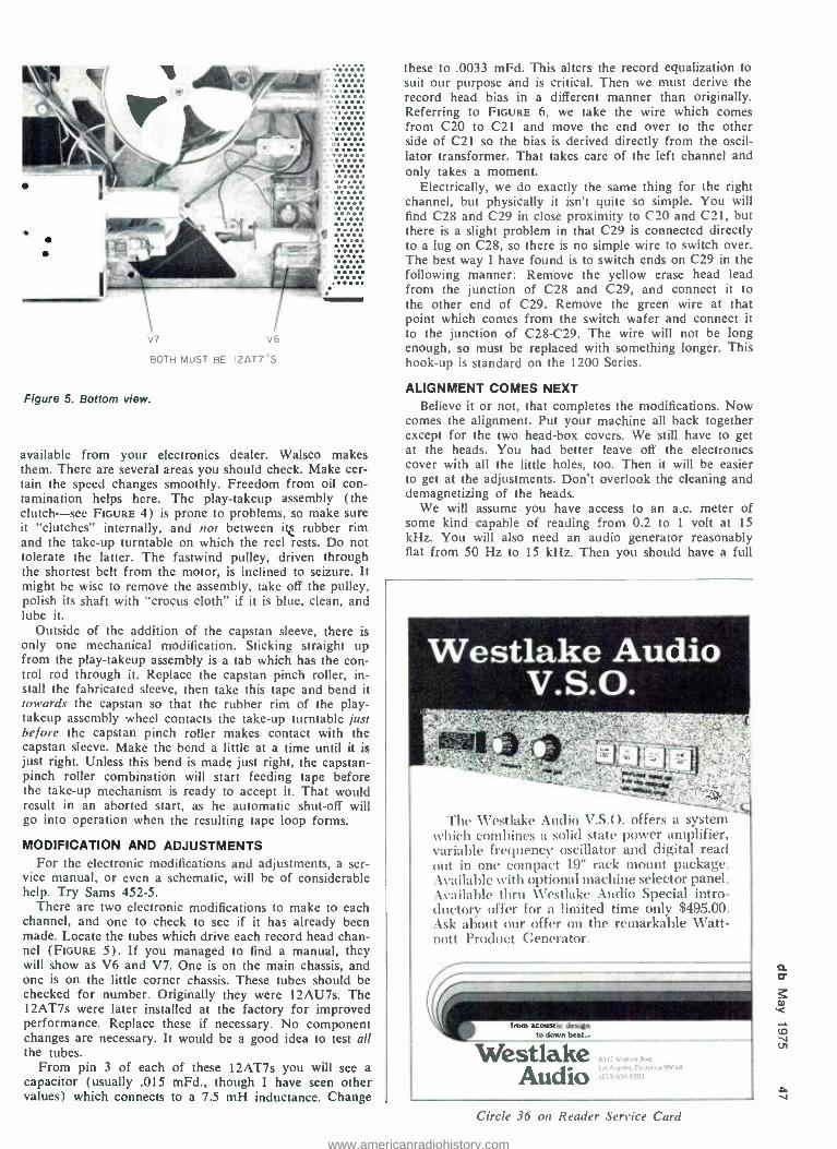
etl .. . . V7 V6
BOTH MUST BE I2AT7'S
Figure 5. Bottom view.
available from your electronics dealer. Walsco makes them. There are several areas you should check. Make cer- tain the speed changes smoothly. Freedom from oil con- tamination helps here. The play -takeup assembly (the clutch -see FIGURE 4) is prone to problems, so make sure it "clutches" internally, and not between itt rubber rim and the take -up turntable on which the reel rests. Do not tolerate the latter. The fastwind pulley, driven through the shortest belt from the motor, is inclined to seizure. It might be wise to remove the assembly, take off the pulley, polish its shaft with "crocus cloth" if it is blue, clean, and lube it.
Outside of the addition of the capstan sleeve, there is only one mechanical modification. Sticking straight up from the play -takeup assembly is a tab which has the con- trol rod through it. Replace the capstan pinch roller, in- stall the fabricated sleeve, then take this tape and bend it towards the capstan so that the rubber rim of the play - takeup assembly wheel contacts the take -up turntable just before the capstan pinch roller makes contact with the capstan sleeve. Make the bend a little at a time until it is just right. Unless this bend is made just right, the capstan - pinch roller combination will start feeding tape before the take -up mechanism is ready to accept it. That would result in an aborted start, as he automatic shut -off will go into operation when the resulting tape loop forms.
MODIFICATION AND ADJUSTMENTS For the electronic modifications and adjustments, a ser-
vice manual, or even a schematic, will be of considerable help. Try Sams 452 -5.
There are two electronic modifications to make to each channel, and one to check to see if it has already been made. Locate the tubes which drive each record head chan- nel (FIGURE 5). If you managed to find a manual, they will show as V6 and V7. One is on the main chassis, and one is on the little corner chassis. These tubes should be checked for number. Originally they were 12AU7s. The 12AT7s were later installed at the factory for improved performance. Replace these if necessary. No component changes are necessary. It would be a good idea to test all the tubes.
From pin 3 of each of these 12AT7s you will see a capacitor (usually .015 mFd., though I have seen other values) which connects to a 7.5 mH inductance. Change
these to .0033 mFd. This alters the record equalization to suit our purpose and is critical. Then we must derive the record head bias in a different manner than originally. Referring to FIGURE 6, we take the wire which comes from C20 to C21 and move the end over to the other side of C21 so the bias is derived directly from the oscil- lator transformer. That takes care of the left channel and only takes a moment.
Electrically, we do exactly the same thing for the right channel, but physically it isn't quite so simple. You will find C28 and C29 in close proximity to C20 and C21, but there is a slight problem in that C29 is connected directly to a lug on C28, so there is no simple wire to switch over. The best way I have found is to switch ends on C29 in the following manner: Remove the yellow erase head lead from the junction of C28 and C29, and connect it to the other end of C29. Remove the green wire at that point which comes from the switch wafer and connect it to the junction of C28 -C29. The wire will not be long enough, so must be replaced with something longer. This hook -up is standard on the 1200 Series.
ALIGNMENT COMES NEXT Believe it or not, that completes the modifications. Now
comes the alignment. Put your machine all back together except for the two head -box covers. We still have to get at the heads. You had better leave off the electronics cover with all the little holes, too. Then it will be easier to get at the adjustments. Don't overlook the cleaning and demagnetizing of the heads.
We will assume you have access to an a.c. meter of some kind capable of reading from 0.2 to 1 volt at 15
kHz. You will also need an audio generator reasonably flat from 50 Hz to 15 kHz. Then you should have a full
The Westlake Audio V.S.O. offers a system which combines a solid state power amplifier, variable frequency oscillator and digital read out in one compact 19" rack mount package. Available with optional machine selector panel. Available thru Westlake Audio Special intro- ductory offer for a limited time only $495.00. Ask about our offer on the remarkable Watt - nott Product Generator.
boat acoustic design to down beat...
Westlake Audio
Circle 36 on Reader Service Card
www.americanradiohistory.com

CI9 C20 .5
3
co
L.BIAS ADJ.
C18 015
(.0033)* LI
75Mh
I r
*(REMOVEI-ei
(ADD)*
L CHANNEL 'L CHANNEL RECORD / ERASE
R67 C28 C29 22K .5 R. BIAS ADJ.
V7B
1 C29 R68 .015
IK 110033)* R69 : L2 51K 75Mh
(ADD)*
1 *(REMOVE)
R. CHANNEL RECORD
CHANGES IN (BOLD)
C30 0011
S3D
R. CHANNEL I1 ERASE R7I
330 2W
Figure 6. Take the wire which comes from C20 to C21 and move the end over to the other side of C21 so the bias is derived from the oscillator transformer.
.1
track -alignment tape such as Ampex 31321 -01 or equiva- lent, with tones from about 50 Hz to 15 kHz at 10 dB below operating level. This is mainly for playback head azimuth adjustment. If you do not own one, get one. If you just can't locate one, there is a reasonable way around it. I'll tell you what to do later.
If you have the alignment tape, connect your a.c. meter to the RIGHT channel output jack on the back of the recorder. The reason for this is that at that jack you have access to the signal from either right or left playback chan- nel simply by flipping the upper left hand knob from STEREO (right channel) to SINGLE (left channel). (See FIGURE 1.) This saves all the mess of plugging and un- plugging the a.c. meter when changing channels. Then connect the LEFT output jack to a suitable amplifier so you can hear what is going on on the alignment tape.
Now, with the fabricated capstan sleeve off, speed at 71 in. /sec. and the upper left hand knob on STEREO, when the 700 -Hz tone comes on, quickly adjust the lower LISTENING VOLUME control to read 0.2 volts, or -12 dBm if your meter has a dB scale. While the 700 -Hz tone is still playing, change that upper left hand selector knob to SINGLE, and while holding the lower LISTENING VOLUME control in its previously established position, turn the upper LISTENING VOLUME control to also read 0.2 volts on the a.c. meter. Mark the position of these two LISTENING VOLUME settings, and do not change them for the remainder of the alignment. They should be at approximately 8 on the numbered scale around them.
FINAL ADJUSTMENTS When the 15 kHz tone comes on, we have come to the
time to adjust the playback head azimuth. Simply go to the little screw on the right side of the playback head triangular base- plate, and carefully adjust it for maximum output on the a.c. meter. It should come up to around 0.2 volts. If it does not, double check your azimuth ad- justment; make sure your playback head shift is in the lower of the two positions. If that doesn't do it, re -clean the head with a reliable head cleaner. In an emergency,
use denatured alcohol. Never use isopropyl. For some reason I have had bad luck with it. It seems to glaze over the face of the head and make things worse than ever. I suspect it dissolves the head lamination binder.
As a last resort, break a woden Q -tip in half, and rather vigorously scrub the playback head gap with the bare wood. Never use anything metal for this! You should be able to bring up that 15 kHz signal to around 0.2 volts on each channel. If it still doesn't come up, check to see if you have the "gismos" mentioned two paragraphs ahead.
So what do you do if you just couldn't come up with a suitable alignment tape? Well, set both LISTENING VOLUME knobs to 8, and take it for granted your listen- ing levels are pretty close. Then put a tape on which has a superabundance of highs, such as bells, cymbals, or glockenspiel, or something like that. Fully turn up the treble response on your listening amplifier which you have connected to the 960, then adjust that playback azi- muth screw back and forth until you locate the point of maximum brilliance of sound. While you have to rely on your ear for this, it should come out pretty close.
This completes the playback adjustments, with one pos- sible exception. Look inside the electronics and see if your machine is equipped with adjustable playback head - swamping resistors. Some units came out with these, and they can give trouble if misadjusted. If yours has them, you will find them right where the playback head leads connect to tie -points in the electronics. They will be one unit: a white ceramic section with two blue adjustments, 11 /a in long and 3/ in. wide. I generally remove the whole thing. It is there to dampen the high frequency response of unusually "hot" heads. By now your playback head likely doesn't need it! Finally, check the erase -head azi- muth. It is not critical, and may he adjusted by sight.
RECORD CIRCUITRY AND HEAD Now we will undertake to align the record circuitry and
head. Get yourself a good quality tape of the type you will generally be using. Put it on the machine in the record mode, at 71/2 in. /sec., with the audio generator connected to both radio -phono inputs and a frequency of 500 Hz, with both the upper and lower radio -phono controls set to around 8 -with both microphone gains set at zero. Ad- just the output of the audio generator until the record level meter on the machine comes up to about the N in the word "normal." Adjust the relative settings of the two radio -phono controls until the meter reads the same for each channel. Remember that the LISTENING VOLUME controls must still be at their previously established set- tings.
With the audio generator at 3000 Hz, and the same out- put as above, adjust the left (C20) and then the right (C29) channel bias for maximum output on your a.c. meter (see FIGURE 7). Perform this operation with care, it is vitally important. You will have to change C20 and C29 quite a bit because we have modified that circuitry. By making our bias adjustments at 3,000 Hz we slightly underbias the machine a predetermined amount at the lower frequencies, but this slightly improves the high fre- quency response in the record mode. Then with your audio generator at 15 kHz, adjust the record -head azi- muth screw for maximum output on your a.c. meter. The record head is the middle one, and its azimuth adjustment screw is the one on the right corner of its triangular base - plate.
At this point, you might want to check the overall fre- quency response of your machine. With this modification it will be normal to have the frequency response gradually taper off somewhere above 4,000 Hz. You might want to devise some way of switching the values of the two capaci- tors you changed from 0.015 to 0.0033 back and forth so
www.americanradiohistory.com

C21 C30
C29 RIGHT CHANNEL BIAS ADJUST
C18
REPLACEMENT (SMALLER THAN ORIGINAL)
R74 AS NOISE 1DJUST
C20 LEFT CHANNEL BIAS ADJUST
Figure 7. View of electronics.
LI 7 5 Mh
R28 METER CALIBRATION
that you can select the appropriate value, for duplicating, or for regular use. This would be the time to decide.
When checking the overall frequency response, make sure the record meter level on the machine is not reading more than the N in the word "normal;" otherwise your high frequency readings may be inaccurate due to pos- sible tape saturation.
NOISE CONTROL With the machine still in the record mode at 71/2 in./
sec., and no signal input, adjust the noise control R74 (FIGURE 7) for a minimum of popping as heard through your amplifier. This adjusts the bias signal for best linear- ity which produces minimum popping over slight irregulari- ties of tape oxide.
Then, still without changing the LISTENING VOL- UME control settings, inject enough signal at 500 Hz from the audio generator to read 0.62 volts, or -2 dBm on the a.c. meter. This is normal operating level, and the record level meter should read on the line between "normal" and "high." If it does not, adjust the meter calibration pot, R28 (FIGuRE 7) until it does. There is only one such ad- justment for both channels, so when you switch the record meter to the other channel by changing the lower left control knob (FIGuRE 1) from L to R (or vice versa), there should be very little difference in the reading. If there is much discrepancy it generally means the bias ad- justments have not been properly made; we suggest you go over them again if such is the case.
The record bias frequency in the Ampex 960 is approxi- mately 100 kHz, and is not critical. But if you don't have a suitable filter between the recorder and your a.c. output meter -and you likely won't have -some bias will likely get into your output meter in record mode. If it does, it generally will be at a level below your wanted signals, so that you can still get the information you want from the output meter. If the bias signal coming through is greater than your wanted signals, it will mask the informa- tion you want to get at. I just mention it as a possibility, but it is unlikely. But if it does happen, you will have to record your signals, then rewind the tape and read your
Deviation in dB From Ampex Standard Alignment Tape
Freq. 31311-01 15 i.p.s.
31321 -01 71/2 i.p.s.
31331 -01 33/4 i.p.s.
15 kHz -1 -1 12 kHz -1 o 10 kHz -1 -Yz
7.5 kHz 0 - Y2 -1Y 5 kHz 0 +1 -1
2.5 kHz 0 o -1 1 kHz - Y2 0 o
500 Hz +1Y 0 o 250 Hz +3 +1 0 100 Hz +3 +1 +1 50 Hz +2 +2 +1Y
To derive these figures each alignment tape was copied at 13 i.p.s. and then compared with the align- ment tape itself.
signals in play mode. That will take a little longer. Now go to the nine little head -mounting screws (three
per head), and put a little touch of radio cement on each so that the cement is in contact with both the screw head and the triangular base -plate. That will lock the screws against possible vibration or shock.
REPRODUCE MACHINE This completes the modification and adjustment of one
machine of your high -speed duplicator system. Only the machine on which you plan on recording the copy has to be electronically modified, if the reproduce machine is in normal condition. However, I would at least want to go through the playback checking and adjustment routine de- scribed here to make sure the reproduce machine is satisfactory. It is a very vital link in the chain. You will have to make the mechanical modifications, nevertheless, and assure yourself of its mechanical integrity. But we think you will want to modify both machines if the sec- ond one is a stereo machine and therefore suitable for either reproduce or record function. You will be surprised at how much faster the second one can be done.
Now that the modifications are complete, you will want to try out your device. This combination should produce superior copies of 71 -in. /sec. masters, as you will notice from the frequency chart at that speed. The chart shows that there is the slightest bass boost, which may almost be beneficial. 71/2-in. /sec. masters also come out very well when reduced to 33/ -in. /sec. copies. Excellent 33/4 -in./ sec. copies can be made from 33/4 -in. /sec. masters, with only the slightest loss of high frequencies, not detectable to my ear. We also have reason to believe that a 33/4 -in./ sec. master will produce an acceptable 1Mi-in. /sec. copy, but we had no way of proving it, since we have no 1 % -in./ sec. playback capability.
The comparisons in the chart were arrived at by dupli- cating the appropriate Ampex alignment tape, then corn- paring the copy with the original.
If you have a need for the capability of making high quality copies at reasonably fast speed and are interested in an absorbing, educational, inexpensive and rewarding project that is well within the capabilities of anyone who has a minimum of test equipment and know -how, the fore- going procedures should help you. For the serious record- ist, this is no toy, but a worthwhile adjunct to your equip- ment, and something you will be using for years. You can add as many machines to the system as your need re- quires, within reason. You might have to figure out a way of starting them all at once if the number gets too big. But the end product is well worth the effort.
A m
www.americanradiohistory.com

ul
Ó o Closing date is the fifteenth of the second month preceding the date of issue. Send copy to: Classified Ad Dept. db THE SOUND ENGINEERING MAGAZINE 1120 Old Counry Road. Plainview. New York 11803
Rates are 50c a word for commercial advertisements. Employment offered or %%anted ads are accepted at 25c per word. Frequency discounts: 3 times. 10 %; 6 times. 20'/; 12 times. 33%.
FOR SALE
BROADCAST AND RECORDING EQUIP- MENT: Scully; Metrotech; Langevine; Electrodyne; Q.R.K.; Micro -Trak; M.R.L.; Nortronics; McMartin; U.R.E.I.; Revox; Crown; Byer; Lamb; Master Room; Stell- avox; E.V.; A.K.G.; Sennheiser; Atlas; Ferrograph; HAECO; Stevenson; Gately; dbx; Advent; Altec; Fairchild; Audio De- signs; 3M; Magnacord; Telex; Inovonics. Disc recording systems; package deals; installations; service. Wiegand Audio, Middleburg, Pennsylvania 17842. (717) 837 -1444.
ORTOFON DYNAMIC MOTIONAL FEEDBACK mono disc cutting system. Complete amplifier system: drive, feedback, and feedback - playback monitor preamp; rebuilt, origi- nal factory parts. Guaranteed. Albert B.
Grundy, 64 University Place, New York, N.Y. 10003. (212) 929 -8364.
MONITOR EQUALIZERS for your Altecs & J.B.L.s are a steal at $75 /channel
FREE ROOM EQUALIZATION with pur- chase of 1/3 octave filters. This is not a misprint. Music & Sound, Ltd., 111/2
Old York Rd., Willow Grove, Pa. 19090. (215) 659 -9251.
S.M.E. Damping Mods -$30.00
SCULLY, ELECTRO- VOICE, Neumann, Shure, Spectrasonics, Quad Eight, Mas- terroom, ARP, Corwn, Microtak, Russco. dbx, Interface, EMT, and others. The Audio Marketplace, Div. United Audio Recording, 5310 Jackwood, San An- tonio, Texas 78238. (512) 684 -4000.
DISCOTHEQUE MIXERS from $325.00; equalizer speakers with built -in power amplifiers; bi -amped systems and com- plete portable discotheque systems. Write us for literature. Dealer inquiries invited. GLI, Box 2076, Dept. D, Brook- lyn, N.Y. 11202. (212) 875 -6992.
AUTOMATED QUAD PANNING THE UNIQUE AQC SYSTEM (PAT. APPLIED FOR)
CAN DO WHAT HANDS CANNOT
4, 8, 16 8 24 INPUTS
VIDEO & AUDIO ARTISTRY CORP. p.o. box 4571, boulder, colorado 80302
(3031499 -2001
LOWEST PRICES IN THE COUNTRY on microphones, power amps, speakers, musical instruments, P.A. equipment, including Peavey, Heil, J.B.L.; huge stock, top brands only. Gratin's 110, 606 Rte. 110, Huntington, N.Y. 11746. (516) 549 -5155.
WHATEVER YOUR EQUIPMENT NEEDS -new or used -check us first. We spe- cialize in broadcast equipment. Send $1.00 for our complete listings. Broad- cast Equipment & Supply Co., Box 3141, Bristol, Tenn. 37620.
THE LIBRARY . Sound effects re- corded in STEREO using Dolby"" throughout. Over 350 effects on ten discs, $150.00. Write, The Library, P.O. Box 18145, Denver, Colorado 80218.
TASCAM REVERBS -$500; Tascam mix- ing consoles -$2,350; Tascam 1/2 -inch recorders -$2,750; Tascam 8 -track re- corders- $4,600. All shipped prepaid/ insured, including free alignment /equal- ization /bias /calibration. Music & Sound, Ltd., 111/2 Old York Rd., Willow Grove, Pa. 19090. (215) 659 -9251.
AMPEX, SCULLY, TASCAM, all major professional audio lines. Top dollar trade -ins. 15 minutes George Washing- ton Bridge. PROFESSIONAL AUDIO VIDEO CORPORATION, 342 Main St., Paterson, N.J. 07505. (201) 523 -3333.
ONE WAY NOISE REDUCTION for cut- ting rooms /tape copies; retains highs, rids hiss /surface noise & clicks /pops by a full 10 -14 dB and costs $150 up per channel! Music & Sound, Ltd., 111/2
Old York Rd., Willow Grove, Pa. 19090. (215) 659 -9251.
CROWN 01200, M600, and M2000; drives RTR "Monitor" speakers, on demo now in our showroom. Barclay Recording, 503 Haverford Ave., Nar- berth, Pa. (215) 667 -3048.
NEW MODELS: Ampex AG440C 2- track, servo capstan motor; Scully 280B; used AG440Bs; used Scully 280, 8- track, new heads, in console, excellent condition; Sennheiser mics. Immediate delivery from stock. Malaco Recording, Jackson, Miss. (601) 982 -4522.
* SERIES "B" MIXING CONSOLE * VARI -BAND 5 SECTION
PARAMETERIC EQUALIZER * DUAL EQUALIZED REVERB * LONG & SHORT THROW SLIDE
FADERS * HIGH BALLISTIC VU METER
P.O. BOX 3187 HOLLYWOOD, CA 90028
(213) 467 -7890
AMPEX 300, 352, 400, 450 USERS -for greater S/N ratio, replace first playback stage 12SJ7 with our plug -in transistor preamp. For specifications write VIF In- ternational, Box 1555, Mountain View, Ca., 94042. (408) 739 -9740.
NEUMANN LATHE, rebuilt, Lyrec motor, Scully saddle with EICO L.P.I., $5,000.00. Write: A. Angileri, 6331 S.W. 80th St., S. Miami, Florida 33143. Phone: (305) 667 -4148.
$1 MILLION USED RECORDING -PA- BROADCASTING EQUIPMENT. Send $1.00 for list, refundable, to The Equip- ment Locator, P.O. Box 99569, San Francisco, Ca. 94109.
COHERENT CONCERT SOUND -more than P.A.! We work with musicians to create an aural environment in concert that matches studio production. (212) 947 -1271.
FOR SALE: 20 Gotham 600 -ohm sliders, $20.00 ea;; Simpson 11/2-inch vu meters, $12.00; passive hi -lo equalizers. $10.00, assorted rotary attenuators, $5.00. (212) 581 -0123.
TUNED ROCK P.A.s Customized high intensity touring /permanent in- stallation sound systems, including narrow band (5 Hz!) feedback sup- pression, detailed regenerative re- sponse Acousta- Voicing /environmen- tal equalization (± 1 dB at your ears), room design /measurement/ treatment, = 15% articulation loss of consonants; 1000s of customized professional products, including fi- berglass horns, consoles, comp /rms/ peak limiters, 18 dB continuously variable electronic crossovers, digi- tal /acoustic delays, omnipressors, phasors, reverb, echo, doubling/ tripling effects, P.A. noise reduction; piezo transducers; frequency shift- ers from: J.B.L. /Altec pro, Tascam. U.R.E.I., Eventide, Gately, Schoeps, Beyer, Crown, Community Light/ Sound, Mom's Audio, McIntosh, Bo- zak, Allen & Heath, etc. etc. All shipped prepaid /insured. Music &
Sound, Ltd., 111/2 Old York Rd., Wil- low Grove, Pa. 19090. (215) 659- 9251.
Inventors /Engineers
www.americanradiohistory.com

ONE STOP FOR ALL YOUR PROFESSIONAL
AUDIO REQUIREMENTS BOTTOM LINE ORIENTED
F. T. C. BREWER CO. P.O. Box 8057, Pensacola, Fla. 32505
BABY BOOM STANDS and a snake, 100' or >, 15 pair or >. Ray Eldred, 2703 W. 9th, Olympia, Wash. (206) 357 -6885.
SOUND SYSTEMS FOR SALE; full rig Rolling Stones quad concert sound sys- tems; like -new Crown DC -300A & DC- 150 power amps; nine frequency band mixing consoles; J.B.L. 2220B & 2130 base speakers; 2440 wide -range drivers; 2395 & 2390 horns; 2405 UHF drivers. all crossovers, cycle cards. cabling &
accessories. Three full systems, best offer one or more. (212) 757 -9086.
WANT TO GO BI -AMP? DeCoursey Electronic Dividing Networks are available from $89.10 (monaural bi- amp) to $205 (stereo tri -amp). Price in- cludes plug -in Butterworth filters; 6, 12, or 18 dB per octave at any desired cut- off frequency. Write for brochure. DeCoursey Engineering Laboratory, 11828 Jefferson Blvd., Culver City, Ca. 90230.
MIXER MODULES: modular construc- tion provides economical route to studio - type mixing console; modules available wth mic /line, pan, echo send, plastic element slide faders; equalization is also available as an add -on module. Typical cost of 6 -In, 2 -out mixer (no EQ) is less than $450.00. Send for catalog: Wall of Sound, 2406 Mountain Rd., Pasadena, Md. 21122.
SCULLY 1/4"-1/2"-2" RECORDERS, im- mediate delivery; console kits, 16/2, $2,995.00, 16/4, $3,295.00, 16/16, $5,495.00, W /E.Q., available wired. All electronics, modular plug -in, Spectra - Sonic cards. Stereotronic Industries Inc. (since 1940), 700 -29th St., Zion, III. 60099. (312) 336 -2222.
DYMA builds custom studio consoles, desks. enclosures. studio furniture. Dyma Engineering, Route 1, Box 51. Taos, New Mexico 87571.
CASSETTE LABELS, blank and custom printed. Free samples. Tarzac, 638 Mus- kogee Ave., Norfolk, Va. 23509.
CATV -MATV PRODUCTS CONNECTORS WALLPLATES SPLITTERS AMPLIFIERS
AVA ELECTRONICS CORP. 242 Pembroke A Lan.downa, Pa. 19050
(2151 254 -2500
NEW YORK'S LEADING PRO AUDIO /VIDEO DISTRIBUTOR for audio. video. broadcast, public ad- dress, and hi -fi systems; represent- ing over 130 audio /video manufac- turers, featuring such names as Ampex, Scully. Tascam, Sony, J. B.
Lansing, Neumann, Altec, McIntosh, AKG, Dynair, T.V. Microtime, UREI, 3M, and other major brands; the largest "in stock" inventory of equipment. accessories, and parts; competitive discount prices; factory authorized sales, service. parts, sys- tems design, installation. Write for free catalog! Martin Audio /Video Corporation, 320 W. 46th St., New York, N.Y. 10036. (212) 541 -5900.
SPLICE TAPE FASTER, BETTER, BY SHEARING. Experts recommend Nagy splicers. Quality long- lasting instrument. Reasonably priced. Details. NRPD, Box 289, McLean, Va. 22101.
EMS SYNTHESIZERS. Find out how you can save money on EMS systems. We promise it's worth your while. Write EMSA, 460 West St. (5), Amherst, Mass. 01002.
REELS AND BOXES. 7" and 5" large and small hubs; heavy duty white boxes. W -M Sales, 2010 Balboa, Dallas, Texas 75224.
SCULLY 16 -TRACK (288 -16); very good condition. new record and play heads, with relapped replacement play head, $12,500. Cookhouse Recording Studios, 2541 Nicollet Ave., Minneapolis, Minn. 55404, (612) 827-5441.
SENNHEISER MKH -105 condenser mic- rophones; factory -calibrated pair, $650; two AKG C -414 condenser microphones with N46E power supply, $850; Beyer M -360 ribbon microphone. $150.; all in -mint condition. Mark Plourd, 11760 SW 98th St., Portland, Oregon 97223. (Weekends) 1-503-639-7787.
STUDIO SOUND -Europe's leading pro- fessional mgazine. Back issues avail- able from June, '73. $1 each, postpaid. 3P Recording, P.O. Box 99569, San Francisco, Ca. 94109.
KING MODEL BOOS TAPE WINDER (hub); pre -recorded tape winder, will wind either 1/4 in. or 150 mil. widths; as new condition. Also used Rangertone resolver, as is. Gary E. Taylor, Conti- nental Film Productions Corp., P.O. Box 6543, Chattanooga, Tenn. 37408.
DYMA builds roll- around consoles for any reel -to -reel tape recorder. Dyma Engineering, Route 1, Box 51, Taos, New Mexico 87571.
FREE CATALOG 8 AUDIO APPLICATIONS
OPAMP LABS.INC. l8t .i óliii 8°, ,VA.
CONSOLES KITS & WIRED
AMPLIFIERS MIC., EO, AC N, LINE, TAPE,DISC, POWER
OSCILLATORS AUDIO TAPE BIAS
POWER SUPPLIES
B.B.C. REFERENCE MONITORS, pre - equalized J. B. L. /Altec monitors; Dahlquist phased arrays; I. M. F.
transmission lines; Infinity electrosta- tics; Crown /McIntosh 16 tt /bridged bi -amps; Scully /Revox A -700 re- corders; Micmix reverbs; Eventide phasors /omnipressors; Lexicon dig- ital delays; dbx /Burwen N.R. com- panders; Little Dipper hum /buzz notch filters; Cooper Time Cube echo send; moving coil Supex /Orto- fon; B & O straight line arms /car- tridges; Schoeps /AKG /Sennheiser condensers; Beyer ribbons, U.R.E.I. comp /limiters /crossovers; Gately pro - kits; Q.R.K. tt. 1000s more. Musk &
Sound Ltd., 1111 Old York Rd., Wil- low Grave, Pa. 19090. (215) 659- 9251.
All Shipped Prepaid + Insured
SINGLE EDGE RAZOR BLADES, tape editing. $23/M. Flyer. RALTEC, 25884 Highland, Cleveland, Ohio 44143.
BODE FREQUENCY SHIFTERS since 1963 ... Advanced designs for electronic music studios and high performance P.A. systems. Synthesizer compatible model with built -in B.F.O., exponential interface, $995.00. Anti -feedback model: audio range 35 Hz -16 kHz for speakers, entertainers, bands, $575.00. Prices f.o.b. North Tonawanda. Delivery: stock to 6 weeks. For details and information on other models, write to: Bode Sound Co., Harald Bode, 1344 Abington Place, N. Tonawanda, N.Y. 14120. (716) 692- 1670.
CUSTOM CROSSOVER NETWORKS to your specifications: 1 or 1000. Power capacities to 1,000 watts. Networks dup- licated. High tolerance air and iron core inductors. Outline your needs for rapid quotation. TSR ENGINEERING, 3673 W. 113th St., Inglewood, Ca. 90313. (213) 678 -1979.
WANTED
WANTED: PORTABLE DUAL TURN- TABLE, low cost. E. Lewy, 853 N. Eu- taw St., Baltimore, Md. 21201.
WANTED: IONOVAC (DUKANE) tweet- ers; state condition and price. Mark Plourd, 11760 S.W. 98th St., Portland, Oregon 97223.
EMPLOYMENT
PROFESSIONAL RECORDING PERSON- NEL SPECIALISTS. A service for em- ployers and job seekers. Call today! Smith's Personnel Service, 1457 Broad- way, N.Y.C. 10036. Alayne Spertell. (212) WI 7 -3806.
WANTED: EXPERIENCED SENIOR RE- CORDING ENGINEER with solid follow- ing to join forces with growing top qual- ity studio. Terms: negotiable. Contact: Jerry Kornbluth, A&J Audio Visual Ser- vices, 119 W. 57th St., New York, N.Y. 10019.
www.americanradiohistory.com

o people/places/happenings
DAVIS BARGER
Don Davis, president of Synergetic Audio Concepts and well known for his teaching seminars, will conduct a series of mini -seminars at the NEW - COM '75 show. The show will run from May 6 -8 at the Las Vegas Con- vention Center. Mr. Davis' seminars will cover the basics to be mastered in order to understand room equali- zation and the more involved area of choosing workable systems and tech- niques. In addition to exhibits by the major professional sound and video products manufacturers, there will be displays by others in allied fields. Free badge application forms may be re- quested from Electronic Industry Show Corp., 22 South Riverside Plaza, Chicago, III. 60606.
Appointment of Robert H. F. Lloyd, as group director of MOS /LSI sys- tems has been announced by National Semiconductor Corp, of Santa Clara, Ca. Mr. Lloyd was the founder of Advanced Memory Systems, Inc. and served as their chief executive officer before coming to National Semicon- ductor. He holds four patents and is the author of six technical publica- tions.
Sanyo Electric Inc. of Compton, Ca. has appointed the Leonard Elliott Company as its manufacturer's repre- sentative in the southeast area, includ- ing Tennessee, Mississippi, Alabama, Georgia, and N. and S. Carolina. The Elliott Company is located in Atlanta, Georgia.
James E. Patterson has been pro- moted to national accounts manager of audio bulk products for BASF Sys- tems, of Bedford, Mass. He will be responsible for national sales and re- lated activities in marketing the com-
a pany's blank cassette duplicating prod- ucts. Mr. Patterson. who has been
SCHNEPP
with BASF since 1973, was formerly associated with the Savin Business Ma- chine Co.
Herman C. Barger has been ap- pointed eastern regional sales man- ager for TDK Electronics Corp., of Garden City, N.Y. Mr. Barger will be responsible for sales of TDK products in 20 states in the eastern part of the U.S. Before joining TDK, Mr. Barger was with the Capitol Records Com- pany.
Filling the newly created position of director of corporate communica- tions at Superscope, of Sun Valley, Cal- ifornia, Harley R. Gleckman will act as a liaison between the company and the financial community. Another po- sition, also in the realm of corporate communications, manager of corporate communications, has been filled by Elyn Rankell. An additional new ap- pointment at Superscope is that of Ned Padwa to the position of general manager, tape duplicating division. New regional vice -presidents have been recently announced: Mario Cannata. New England; Joseph Deo, New York; Richard Isola, Detroit; Robert Neuhaus, Southwest; David Pedrick, Northwest.
Harro K. Heinz has been appointed president of the Rauland -Borg Corp. of Chicago. Mr. E. N. Rauland will continue, as chairman of the board, and chief executive officer. Mr. Heinz has been with Rauland -Borg for a year. Previously, he was associated with Bogen and Fisher Radio.
Several new appointments have been announced by the TEAC Cor- poration, of Montebello, Ca. Masa- kasu Sekine has been named video sales coordinator for the American
company. He was formerly employed by TEAC in Japan. Jorge Montero has been selected to coordinate in- creasing sales activity in Latin Amer- ica. Mr. Montero, who is a native of Ecuador, was formerly associated with Audio Magnetics.
Richard D. Schnepp has been named vice president of commercial/ professional sales for Jack Carter As- sociates of N. Hollywood, Ca. Mr. Schnepp has been with the organiza- tion for the past nine years.
A revised and updated third edi- tion of the FM ATLAS AND STA- TION DIRECTORY is now avail- able from FM Atlas, Box 24, Adolph, Minn. 55701, at a cost of $2.50. Some 4000 f.m. stations are listed from Panama to Greenland. Data are given on individual stations' formats, pow- ers, heights, stereo capability, vertical polarization, frequencies and call let- ters. The directory also lists network and affiliations and stations having a 67 kHz SCA and what they actually program on this channel. Also in- cluded are outline maps showing f.m. cities and frequencies of North Amer- ica. The directory was prepared by Bruce F. Elving.
Sudden Rush Music, of the Bronx, N.Y. has initiated a new service. They will supply studio quality artists, read- ers and non- readers, for session work at both union scale for mastering and at a special reduced rate for all demo and production /spec work. Musicians are available on instruments ranging from harmonica to vibes to synthe- sizer, capable of producing rock, pop, soul, and country music. Musicians experienced in translating a composer or producer's concepts to the fingering and style of their instruments are available. Information can be obtained from Michael Berman at Sudden Rush Music, 750 Kappock St.. Bronx. N.Y. (212) 884 -6014.
Two engineering department execu- tives have been promoted by Shure Brothers, Inc. of Evanston, Ill. Bern- hard Jakobs has been named director of development and application engi- neering, directing all activities of the engineering services department. Don- ald Patten has been appointed man- ager of engineering services, respon- sible for application engineering ac- tivities, including data sheet and book- let preparation.
www.americanradiohistory.com

À-7300
Just because we don't call it professional doesn't mean it couldn't be.
We don't call our A -7300 a professional tape recorder - we make those too, and we know the difference.
On the other hand, the A -7300 is far better than the typical high fidelity component. Consider, for example, some of the professionalfeatures...a servo controlled direct drive capstan system, full IC logic transport controls, four balanced mic inputs with XL-type connectors, a flip -up hinged head cover for easy maintenance and editing.
Yet, in the final analysis, it isn't what it's called, but what it does that counts. You'll have to determine for yourself whether or not it meets your specific needs, and you can do that only by examining and operating it for yourself.
You'll find that our retailers are well informed and helpful in general. Rare qualities, so there can't be many of them. You can find the one nearest you by calling (800) 447 -4700? We'll pay for the call.
`In Illinois, call 1800) 322 -4400.
The leader. Always has been.. TEAC Corporation of America, 7733 Telegraph Road, Montebello, California 411640.
www.americanradiohistory.com

At the 51st AES Convention in L.A., May 13 -16,
Automated Processes will demonstrate a radically new concept in Audio Mixing...
A Completely Programmable Mixdown Console called AUTOMIX.
Automix as a manual mixdown console is
incomparable. As a programmable console, it permits new standards of perfection and artistry.
You may capture every detail and nuance of a mix from up to 32 inputs and 4 echo channels. When programmed, your mix may be precisely repeated as often as desired, or each element of sound on any track may he improved individually or in combination.
The audio paths are entirely separated from the DC control circuits. Voltage con- trol amplifiers and state variable devices in
the audio paths provide for all functions: level, localization, reverberation, and equali- zation. Control of multiple audio paths by a
single manipulator (grouping) is possible for all functions. An optional video screen dis- plays the quad sound field, identifying each input, as a numeral, in its respective aural position.
Extraordinary performance is achieved at a very ordinary price. Automix,even with a
companion Automated Processes' studio mixing console,can be obtained at substanti- ally lower cost than a conventional console of comparable numerical capabilities.
Be sure to see AUTOMIX in "hands -on" action at the AES Convention. Visit Auto- mated Processes' Demo Rooms 474/76, on the 4th floor of the L.A. Hilton!
AUTOMATED PROCESSES, INC_ 80 MARCUS DRIVE, MELVILLE, NEWYORK 11746.516- 694 -9212
Circle Il on Reader Service Card
www.americanradiohistory.com