폭발해석결과의설계반영 - cadgraphics.co.kr due to gas explosion would lead to...
12
1 폭발해석 결과의 설계 반영 폭발해석 결과의 설계 반영 2008 2008년년12 12월월11 11일일 현대중공업㈜ 현대중공업㈜ BHN 폭발/화재 (2005.7) 2
Transcript of 폭발해석결과의설계반영 - cadgraphics.co.kr due to gas explosion would lead to...
1
폭발해석 결과의 설계 반영폭발해석 결과의 설계 반영
20082008년년 1212월월 1111일일
현대중공업㈜현대중공업㈜
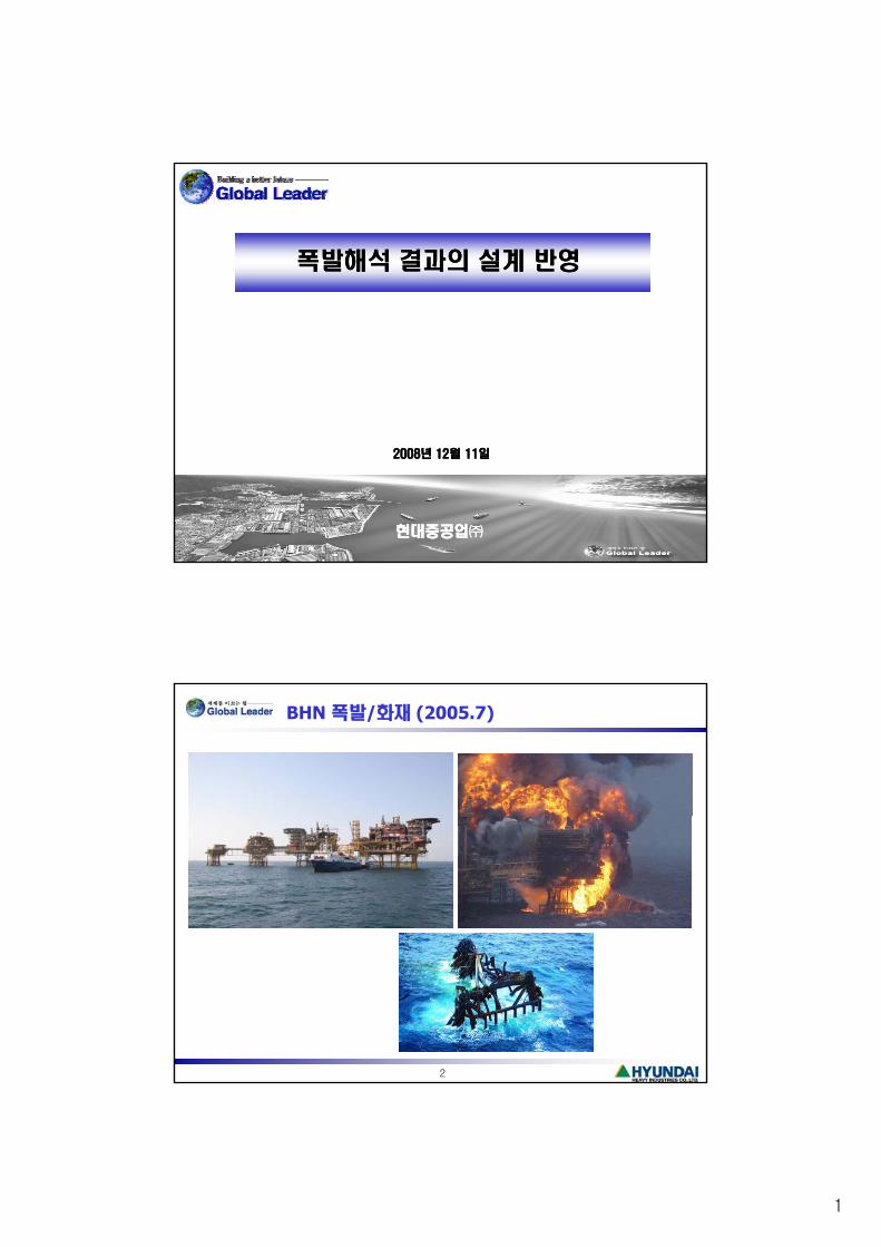
BHN 폭발/화재 (2005.7)
2

2
Piper Alpha 폭발/화재 (1988.6)
3
165 people killed
Lord Cullen Survey
Explosion
Explosion
Combustion of a premixed gas cloud containing fuel and oxidizer that can result in a rapid rise in pressure.
Explosion occurs at a gas cloud with a concentration between the UFL and LFL.
Deflagration / Detonation
Combustion wave propagating at subsonic/supersonic velocity
Overpressure of # mbar ~ # bar / upto 20 bar
Definition of typical parameters (time-pressure history)
4

3
Explosion Loads
Overpressure loads: result from increases in pressure due to expanding combustion products
Drag loads: result from the flow of air, gases, and combustion products past an object.
Shock loads: a very small duration compared to the whole blast.
Global reaction loads: result from differential pressure loading, have same time scale as the pressure variation.
Explosion Load Parameters:
5
Gas Cloud Size, Ignition Location, Congestion, Confinement, Ventilation
Explosion Design Loads
Main & Secondary Structural Members: Overpressure & Drag load
Piping or Equipment (Support): Drag Load, Pressure Difference & deflection /acceleration
Blast Wall, Deck & Panel: Overpressure
Blast Loads
Drag Load: ACLoadDynamicAvCF DDD ⋅⋅=⋅⋅⋅= 2
21 ρ
6
Pressure Difference Load:
where, PDF = Pressure Distribution Factor
PDFAreaWindagePFPD ⋅⋅Δ=

4
Blast Load for Piping & Vessels
Large obstacles (Dia. > 2 m): The force is determined from the Differential Pressure
Force,
For cylinders, PDF = 2/π.
)FactoronDistributiPressure(PDFAreaWindagePFPD ⋅⋅Δ=
Intermediate obstacles (0.3 m < Dia. < 2 m): Both Drag and Pressure DifferenceLoads are significant in the flow direction.
Small obstacles (Dia. < 0.3 m): Drag loads dominate for obstacles in particular in regions of high gas velocity near vents.
Drag Load, ACACvF DDD ⋅⋅=⋅⋅⋅⋅= PressureDynamic21 2ρ
7
If the general level of Dynamic Pressure loads is not known then it is acceptable to take a load equal to 1/3 of the overpressure at the location for the DLB load case.
Direct Load Measurement (DLM) Method
DLM for Piping & Vessels
8

5
Interaction Flow - Explosion
Layout
l d l
Safety Structural
3D Model (Layout)
Structural Layout1
Explosion Modeling1 (CFD)
Response Analysis*
Structural Details/Layout2
9
Implement CAD Model
Explosion Modeling2 (CFD)
* For Structure, Blast Wall, Decks, Vessels, Equipment, Piping/Support, etc.
Explosion Design Loads
Design Principles
Deterministic Design
Probabilistic Design
Risk Based Design (RBD)Risk Based Design (RBD)
Calculation of Explosion Loads
Empirical Models - Experimental data
Phenomenological Methods - Physical processes & experimental
work
Numerical Models - Computational Fluid Dynamics (CFD)
10
p y ( )

6
Explosion Risk Analysis
Probabilistic Analysis
Ventilation Simulation
Geometry 3D Model
Explosion Simulation
Dispersion Simulation
Ventilation Conditions
l
Ignition Intensity
Weather Data
L k
11
Explosion Load Explosion Probability
Explosion Risk (Frequency vs. O.P curves)
Leak Data
Input Data
Geometry
CAD geometry (3D)
Anticipated Congestion Model (ACM)
12

7
Ventilation Simulation
Calculate the internal ventilation distribution - combinations of wind direction/speed (typically 12 simulations).
Establish the ventilation conditions in the areas of concern
Air Change per Hour (ACH)
Flow Pattern
13
Dispersion Simulation
Calculate an equivalent stoichiometric cloud size distribution
Combinations of variables: 100-200 simulations
Leak locations
Leak directions
Leak rates
Inventories
Ventilation conditions
14

8
Explosion Simulation
Calculate the explosion loads and impulses from the different cloud sizes
Necessary data to establish the probability of exceedance curve for explosion risk: 70 – 150 simulations.
Cloud sizes
Cloud locations
Ignition locations
15
Explosion Simulation
Ignition Location Frequency of Exceedance Curve
16
9
Criticality of SCEs
Safety Critical Elements (SCEs): any component part of structure, equipment, plant or system whose failure could cause a major accident events (MAEs).
Criticality 1: Elements which must resist to an “extreme event”. Items whose failure due to gas explosion would lead to major/catastrophic fire escalation or major impairment of escape possibilities.
Performance Standard – These items must not fail during the Ductility Level Blast (DLB) or Strength Level Blast (SLB), ductile response of the support structure is allowed during the DLB.
Example:
Primary structures,
Blast Wall
17
Blast Wall,
critical equipment (Separator, Risers, ESDVs, LQ/Muster Shelter, Flare Header, FW ringmain, etc.)
Criticality of SCEs
Criticality 2: Elements which must resist to a “low-level event”. Items whose failure due to gas explosion would contribute to significant fire escalation locallybut not of such magnitude as to be outside the fire design scenario.
Performance Standard – These items must have no functional significance in an explosion event and these items and their supports must respond elasticallyexplosion event and these items and their supports must respond elastically under the SLB. Equipment and pipes designed for a less severe but non-the-less substantial explosion event.
Example:
Secondary structures,
HC containing equipment/supports,
HC piping,
SDVs
18
SDVs,
2nd FW network/deluge skid,
Piperack,
E&I buildings, etc.

10
Criticality of SCEs
Criticality 3: Equipment not designed or assessed for explosion. Items whose failure in an explosion event would contribute to minors effects.
Performance standard – These items have no functional significance in an explosion event and must not become or generate projectiles.
19
Blast Load Levels
Ductility Level Blast (DLB):
Design level blast load
A low-probability, high-consequence event: 10-4/yr frequency of exceedance
Extreme design event, progressive collapse analysisg , p g p y
Ductility Ratio (μ),
Strength Level Blast (SLB):
Reduced blast load
A higher-probability, lower-consequence event
Elastic response
F t d i t
limitelasticatdeflectiony,deflectiontotalδwhere,, el ===elyδμ
20
Frequent design event
Equivalent Static Load,
γ : Dynamic Amplification Factor (DAF),
If computations are not available for overpressure for SLB, then 1/3 of the blast loading from the DLB may be used for SLB.
peakstatic LL ⋅= γ

11
Effect of Loading Regime
21
Blast Load Levels
Ductility Ration (μ): limitelasticatdeflectiony,deflectiontotalδwhere,, el ===elyδμ
22

12
References
[1] Jerzy Czujko, Design of Offshore Facilities to Resist Gas Explosion Hazard Engineering Handbook, 1st Ed. 2001
[2] UKOOA, Fire and Explosion Guidance, Part 1: Avoidance and Mitigation of Explosion, Issue 1, Oct. 2003
[3] API, RP 2FB, Recommended Practice for the Design of Offshore Facilities against Fire and Blast Loading, 1st Ed., Apr. 2006
[4] FABIG, Technical Note on Protection of Piping Systems subject to Fires and Explosions, Technical Note 8
[5] NORSOK, S-013, Risk and Emergency Preparedness Analysis, Rev. 2, Sept. 2001
[6] Gexcon, Explosion Modeling Reports, 2008
23


![Fire and Explosion Hazard Management[1]](https://static.fdocuments.net/doc/165x107/577cd7541a28ab9e789eb4df/fire-and-explosion-hazard-management1.jpg)