~ ~Distrib GROMETI
135
rIW !E ..... - - - - -_ _ _ _ n r. ... . . ... . \,- -.. 0c I Dsnuo U .::'e 'II "COLOR A UGMENATIONNH PHIIPP S LAN •1: 1 " i1 IN Lc AN2cr.az - ~ DISTRIB _ T -N STA T--ENTT A W~ITL Appovea for -ziibfc .-. ease; I ~ ~Distrib :oTl~ e.. GROMETI RAINFALL AUGMENTATION IN THE PHILIPPINE ISLANDS ! ~Reprodut" hY• NATIONAL TECHNICAL <II , INFORMATION SERVICE U Spnngfield. Va, 22151 • NAVAL WEAP(ONS CENTERSCHINA LAKE, CALIFORNIAONWý tP 5097e MAY 19?1 ' ' I
Transcript of ~ ~Distrib GROMETI

rIW !E ..... - - - - -_ _ _ _ n r. ... . . ... . \,- -..
0c
I Dsnuo U .::'e
'II"COLOR A UGMENATIONNH PHIIPP S LAN
•1: 1 " i1
IN Lc AN2cr.az
- ~ DISTRIB _T
-N STA T--ENTT A
W~ITL Appovea for -ziibfc .-. ease;
I ~ ~Distrib :oTl~ e..
GROMETIRAINFALL AUGMENTATION IN THE PHILIPPINE ISLANDS
! ~Reprodut" hY•
NATIONAL TECHNICAL <II, INFORMATION SERVICE
U Spnngfield. Va, 22151 •
NAVAL WEAP(ONS CENTERSCHINA LAKE, CALIFORNIAONWý tP 5097e MAY 19?1' ' I

UNCLASSIFED 18,gL
DOCUMEN4T CONTROL DATA.- R &D
Cinal ake. CA 93555 2 RU
3 REPORT TITLE
GROMET 11: RAINFALL AUGMENTATLION IN THE PHILIPPINE ISLANDS
a EesCagPTIVE NOTES .p.I-typ..dii.c.. dutes)
S AUl TII004SI (0`021 OAR. 0nId0 WOOL las 1.14000e)
P. St.-Ainand, D. W. Reed, T. L. Wright, S. D. Elliott
* REPORT DATE 70. TOTAL NO Or PACES lb. NO or mars
May.i.-1 ________ 110 4S.CONTRACT *It GRAN4T NO 90. ORIGINATOOWS REPORT NUNSCEISI
Is. PRO.JECT NO. ___________________________________5097_______________
AIRTASK A5405401 216D 0W3717000 WMP59C. Ob. OTHIER REPORT NOISI rA,,, 09W oftor Roy he a. ... ,gd
so. DISTRIOUION STATEMENT
APPROVED FOR PUBLIC RELEASE; DISTRIBUTION IJNLIN~iTED.
SUPPLEMENTARNava OESJ PNOUNAir Systems Command
Naval Material Command________________________________Washinitton, DC 20360
-. IS A@STtA4!T
-A severe drought in the Philippine Islands during 1968 and 1969 kuv PhilippineGovernment to try cloud seeding as a means of rainfall augmentation. With the help of theUnited States, a silver iodide seeding project. GROMET 11, was conducted over the entirearchipelago from the end of April through mid-June 1969. Pyrotechnically generated silveriodide was released in updrafts in growing clouds. and through judicial placement and timing ofseedingp events individual clotids were organized into larger cloud systems. Rainfall estimated asat leasy X 1010 cubic meters of water fell from seeded clouds. The precise extent of rainfallaugmentation resulting from seeding cannot be calculated: nonetheless. rainfall augmentationfro-n tropical cumulus clouds was accomplished in a simple operational manner. Benefitsderived, at least in part. from the project included marked improvement in the agriculture.increased sugar production amnounting to 43 million US. dollar%.. and -.-qmented crops o: riceand corn sufficient to make anticipated importation unnecessary, In addition. local personnel
46 were trained in seeding techniques. Because of the success of GROMET 11 the Government ofthe Philippines conducted a similar operation du-ring 11970 and planned another for 1971,.
D D !"006 1473 (PAGE 1) UNCLASSIFIEDI/f 0110760 sewnts ciassuaic-attee

UNCLASSIFIE i)Seciarimy Claaasilcationj
KIY WORDS LINK A LINK 8 LINK C
ROLS WT ROLE WT ROLE WT
Cloud Seeding TechniquesCold ('umulus SeedingCloud SeedingSilver Iodide SeedingRainfall StimulationRainfall EnhancementGROMET IIPhilippine Rainfall AugmentationPyrotechnic Seeding of CloudsAirborne Seeding of CloudsWeather Modification
DD .No.,1473 (A)UNCLASSIFIED(PAGE 2) ' *curitv Classifictiuon t

I NWC TP 5097
LI
I GROMET if.RAWNFAL AUGMENTATIO IN Th PLPPNE IISLANDS
II
Ii
byP St.-AmandIICaptain D. W. Reed. IJSART. L. WrightII S. D. Elliott
Research Department
I'* .
j!1 -A
II APPROVED FOR PUBLIC RELEASE OIS1RIB.-TIO\, U\LI\IT
NAVAL WEAPONS CENTER S CHINA LAKE. CALIFORNIA SMAY 1971

ABSTRACI
A severe drought in the Philippine Islands during 1968 and 1969 led thePhilip1 ,tne Government to try cloud seeding as a means of rainfall augmentation.W.di the help of the United States, a silver iodide seeding project. GROMET I1, was
conducted over the entire archipelago from the end of April through mid-June 1969.Pyrotechnically generated silver iodide was released in updrafts in growing clouds.and through judicial placement and timing of seeding events individual clouds wereorganized into larger cloud systems. Rainfall estimated as at least 3 X 10¹⁰ cubicmeters of water fell from seeded clouds. The precise extent of rainfall augmentationiesulting from seeding cannot be calcula:ed: nonetheless. rainfail augmentation fromtropical cumulus clouds was accomplished in a simple operational manner. Benefitsderived, at least in part. from the project included marked improvement in theagriculture, increased sugar production amounting to 43 million U.S. dollars. andaugmented crops of rice and corn sufficient to make anticipated importationunnecessary., In addition, local personnel were trained in seeding techniques. Becauseof the success of GROMET i1 the Government of the Philippines conducted asimilar operation during 1970 and planned another for 1971.
NWC Technical Publication 5097
Published by ........ ... ... . . Publishing Division
Technical Information DepartmentCollation ............. Cover, 58 leaves. DD Form 1473. abstract cards
First printing .-............................ .... 500 copiesSecurity classification ................. ..... UNCLASSIFIED
iiii 4
K' NAVAL WEAPONS C(E N T E RAN ACTIVITY OF THE NAVAL MATERIAL COMMAND
I ' W. J. Moran. RADM. USN ........... . .. Commander
H.G. Wilson .-.. .......... ... Technical Director
Sr FOREWORD
GROMET II wa, a rain enhancement project undertaken in the PhilippineI Islands at the request of the Philippine Government toward the end of a period of
severe diought, The U.S. Air For;ce had operational responsibility for GROMET il.and the Naval Weapons Center provided technical d~iection under AIRTASK
A5405401 216D OW37170000. Airborne Pyrotechnic Seeding Devices. fromAIR-540. Naval Air Systems Command.
Between 28 April and 18 June 1969. 58 seeding rmssions were conducted.Each had as its primary objective the production of useful rain. The testing and
"- refinement of NWC-d veloped cold cumulus seeding procedures were secondaryobjectives. The extent to which each of these objective. was realized is the subjectof thi, report.
Released by Under authority ofPIERRE ST.-AMAND. Head HUGH W. HUNTER. HeadEarth and Planetar" Sciences Dirision Research Department
"12 Ap:il 1971
I
iiiI
NWC TP 5097
I
CONTENTS
lntrodu;tion ... ................................
Background .... .............................................
. Project GROMET If ................................ .......... . 2Organnzation ............................................... 2"Air Traffic Control .......................................... 2
. Equipment and Instrumentation ...................... ........... 3Project Operation ...................... ...................... 8
"" Philippine Meteorological Situation ................... I..... .... .1 10Meteorological Periods ....................................... 10A Natural Rainfall Process ............ 1i
"Cloud Seeding Techniques ........................ ....... !IWind Shear Conditions .. .............. ..... 17Flight Procedures in Cumulus
"Penetration .. .. .. .. ........ . 34Factors Affecting Seeding Success .......................... 40Tactics of a Typical Mission .............. ... ......... 45
Project Findings ............. .... .. .. .... 50Preseed and Postseed Kain Intensities ................. . 54Estimates of Amount of Rainfall ........... .......... . 57Seeding-Agent Requirement ...................... . ..... . 58
i Ground Measurements of Rain atClark AB ... ................. 60
"Radar Interpretations of Rainfall for TwoII Operations ............................. . ..... . 63
Impact of GROMET If on Philippine Economy ......................... 71
Conclusions . ..... ............... ...................... . 72
Recomneruat ions .................................... 72Geneial ...................... 72Sp(cifi,.............. .................................. 73
Acknowledgment . ................................ ........... 76
Appendixes:A. Summary of Operations ......................... ....... 719B, Operational Considerations ....... .................... 91C. Preliminary Cloud Studies in the
Philippines - 1969 ............... .. ............. . 95D. Observations at GROMET II ......... 1......... 01
References ...................... ......................... 108
! V

NWC I'P 5097
TAIWAN
,,.HONG
e!
0 j
!a20" -------
_ _t _ _ I
SOUTH CHINA SEA LUZON
PHILIPPINE SEA .,§.
I
MINDORO
SMALAYSIA \ W
1.1
101130
Philippine I'land%.
A
• •.-,,Ivi -.. -i
S• j •. --.r?=,

NWC TP 5097
+ICONTENTS
I Introduction ......................................... I
1" Background .................................................
Project GROMET II .............................. ....... 2
Organization ................................................ 2Air Traffic Control ...................... 2
Equipment and Instrumentation .................................. 3Project Operation ............................................. 8
Philippine Meteorological Situation ................................. 101 Meteorological Periods ............................ . ..... .... 10A Natural Rainfall Process .... ........ .1 ... .... . 1 I
Cloud Seeding Techniques ..... ... .. . ........ 1Wind Shear Conditions ................. 17
Flight Procedures in CumulusPenetration ......... .. ................ 34
Factors Affecting Seeding Success . 40Tactics of a Typical Mission ......... .. ............ 45
Project Findings .... .... . ......... 50
Preseed and Postseed Rain Intensities . . .... .. .. ... 54
Estimates of Amount of Rainfall ............... ............. 57Seeding-Agent Requirement ...................... 58
Ground Measurements of Rain atClark AB ... . .. . . ... . ... . . . . . . . . .. . . 60
Radar Interpretations of Rainfall for TwoOperations . ................. ..... ... ................. . 63
Impact of GROMET I1 on Philippine Economy ................ ........ 71IConclusions . . . . .. . ... . . ..I .. 72
Recommendations ......... I............. .. .. .. .. . ........ 72General .......... ...... ........................ . 72
Specific ...... ......... 73
Acknowledgment ............ ................ 70
If Appendixes:A. Summary of Operatiors . .......... 79B. uperational Considerations ................................... 91
3 C. Preliminary Cloud Studies in thePhilippines - 1969 ...... ................................. 95
D. Observations at GROMET I! ............... .... ........ 101
* References ......................... ................. 108
I V

SNW ITP 5097
TAIWAN
4ý420'4
SOUTH CHINA SEA LUZON
PHILIPPINE SEA
100.d~. . q" '.
• -J i
• •3. .... •~, a>-'"W-
120 3
Philmppm InWand-.
ii

I NWC TP 5097
INTRODUCTION
This report describes GROMET Ii, the Philippine rainfall augmentation projectconducted by units of the U.S. Air Force and the Naval Weapons Ceater with thecooperation of Philippine agencies from April to mid-June 1969. (The name of theproject is derived from the words agronomy and meteorology.) Included in thereport are discussions of data-gathe.ing equipment, seediiag materials and techniques,details of a typical seeding mission, and iesults from visual, rain-gauge, and radarinterpretations of amounts of rainfall from treated clouds. The impact of GROMET
!1 on Philippine agriculture is considered. GROMET 11 had the additional purpose oftraining local Philippine personnel in secding techniques. Although GROMET !1 wasnot set up as a true experiment because of the urgency of the need for rain.
5• guidelines are also given here for the conduct of a more rigorous cloud seedingexperiment, A summary of all project operations appears in Appendix A. AppendixB gives some suggestions based upon experience from this project for the efficientconduct of future rainfall augmentation prosgrams. Appendixes C and D are theobservations of two meteorological consultants.
BACKGROUND
The Philippine Islands, jewels of green in a caln blue sea, have been famous
for the bounteous climate that furnished all the water needed for domestic andagricultural purposes and for the growing of some of the world's finest hardwoodforests. With growing population and increased planting, however, water needsbecame critical, and water storage and distribution systems could not keep pace withthe increased water demand.
Thus, in 1968 the country begat to feel the effects of a gradually increasingdrought. Still dependent upon natural rainfal!, crops suffered, with great danger tothe national economy (Ref. 1). The Philippine bureau of Agricultural Economicsestimated a drop of 8% in rice production. Reports from the Visayan Islandsshowed that Leyte faced a shortage of corn for the first time, The Philippine SugarInstitute concluded that the drop in sugar yield would prevent the Philippines f'om
meeting the US. sugar quota and might lead to reduction of future sugar quotas.The availability of domestic and irrigation water was reduced. Operations at someU mines were in danger of curtailment because of€ lack of water for milling and
*

NWC TP 5097
processing. As the season wore on and little or no rain fell between January and theend of Apti1 1Q46. crops in the fields turned brown and died, and the soil becametoo hard to plow.
Public alarm became widespread. the Philippine Government moved to let acontract with a commercial firm to seed warm clouds over the sugar-producing areas, iand a similar, larger effort was launched by the Philippine Air Force. Frommid-March until the end of June, warm clouds were seeded at cloud tops ataltitudes between 5,000 and 10,000 feet with brine solution, crystalline salt, orpowdered urea.
Although this effort involving 196 flights was successful in producing rain, itwas early recognized that locally available resources were inadequate to meet thewidespread water requirements. Therefore, additional help was sought from theUnited States. Project GROMET 1i was the name given the U.S. project.
PROJECT GROMET !1
ORGANIZATION
Project GROMET 11 was organized in response to a request for help from theUnited States from President Ferdinand Marcos of the Philippines. The request camethrough the U.S. Embassy in Manila and the U.S. State Department to theDepartment of Defense.
President Marcos appointed Mr, Edgardo Yap, his special consultant for waterresources and an officer of the Philippine Sugar Institute, as his specialrepresentative to handle liaison with participating Philippine agencies. Control of theUS. effort resided with the American Minister, Mr. James Wilson, US. Chargid'Affaires. The Defense Attachi, COL Alfred Patterson, USAF, served as ProjectDirector. COL Phillip Loring, IISAF. 13th Air Force Director of Operations, wasProject Coordinator; LTCOL Theodore Mace, USAF, Commander of Detachment 2,9th Weather Reconnaissance Wing, was OferationA, Director; and Dr, PierreSt.-Amand of the Naval Weppons Center was Scientific Director.
Operational responsibility was assigned to units of the US. Air Force, andtechnical help was given by advisors from NWC. Clark ',ir Base (AB) on Luzon wasthe base of operations.
Participating Philippine agencies included the Philippine Air Force, thePhilippine Weather Bureau, and the Philippine Civil Aviation Authority.
AIR TRAFFIC CONTROL
Air traffic over the Philippines is not heavy, except around central Luzonwhere numerous commercial flights converge on Manila International Airport andmilitary aircraft are operating out of Clark AB, Cubi Point Naval Air Station (NAS),
2

fl! NWC TP 5097
Sangley Point Naval Station (NS). and Basa. Interisland traffic% is modest.It was decided. folloving discussion with civil and military authorities, to
conduct the seeding operations under special visual flight rule clearances in a block
airspace between flight levels 180 and 220 (18.000 and 22.000 feet).To make effective use of airspace. the Philippine ar'lupelago was divided into
five areas. Clearance was granted by radio to utihie one or miore of the GROMET
11 operating areas, occasionally dividing them into eastern and western portions.
Communications were available plane to plane and with Clark Approach
Control. Clark Airways, Clark Weather Radar, Detachment 2 of the 9th Weather
Reconnaissan.e Wing (Dodo Control). Manila Approach Control. Manila Center. and
Cebu Center.Navigational aids consisted of UHF tactical air navigation (TACAN) on Luzon.
a tew vortacs, and numerous nondireciional beacons. Navigation, especiallypinpointing seeding locations, was frequently done by radar,
ii . The US. and Philippine traffic' control system functioned smoothly, and nodifficulties were experienced in navigation or in air traffic control.
EQUIPMENT AND INSTRUMENTATION
i Aircraft
Project aircraft were two WC-130 Lockheed Hercules aircraft sent to Clark ABby the 54th Weather Reconnaissance Squadron at Guam. The WC-130 (Fig. I) is afont-engine turboprop transport capable of extended fliht. Except for its cost (a
I less expensive aircraft could aiso be used). it is an excellent aircraft for cloud
seeding and weather research. NOT REPRODUCIBLE
I
I FIG. I. WC-I30 Aircraft Used on GROMJET !t Mi-,ions.
:13

NWC TP 5097
The -'•o anrcraft were equipped for cloud seeding by the addition of one or
two 20-unit A4- p.hotoflash racks mounted on one or both sides of the plane below
and aft the h ing. The flight deck area of each plane had an opening for a standard
Very pistol.
Seeding Agents
Pyrotechnic seeding agents (Fig. 2) were used exclusively in GROMET I1.
These were fired from either a standard photoflash ejector rack or a standard Very
signal pistol. (Fig. 3.)
Three different seeding agents were employed, LW83, EW20. and TB2. The
compositions are Si-en in Table 1, and the agents are described in detail in Ref 2.
The EW20 and TB2 agents differ only in type of polymeric binder. The charges are
of pressed pyrotechnic. Silver iodate is reduced by a metal fuel and the binder to
produce silver iodide. aluminum-magnesiumn oxide spinei, and, in the case of EW20
and TB2. some potassium oxide and a minor amount of potassium Odide,
The activity curves shown in Fig. 4 are considered the most reliable, although
these values are a little lower at -20 0C and higher at warmer temperatures than
values sometimes given.The smoke particles produced by the burning seeding agents are mali-ly
between 0.05 and 0.1 micron in radius, with a relatively few particles approaching a
l--nicron size. The LW83 produces a more monodispersed smoke than the other two
-[*..
FIG. 2. Cutaway View of DummyPyrotechnic Round for the A-6Photoflash Rack. Note simulatedcharge and balsa wood filler. Verypistol rounds are shorter an thereforerequire no balsa fller: they also havepercussion rather than electrical FIG. 3. Weather Officer Firing Very
primner Pistol in WC-I30 Aircraft.
4

SI NWC TP 5097
TABLE 1. Composition ofSeeding Agents.
Composition. wt. %
Material LW83
precombustion: 1Aluminum ....... 12 11Magnesium ....... I 11
t Potassium nitrate 0 I 44Binder ...... 6 6
Postcombustion:Silver iodide ...... I 20
(1009) (209)
1 1015
4 10 14 -
i0 EW20
9T9
(10 13
In >/
1010 /0 -5 -10 1 2
TEMPERATURE. C
FIG. 4. Activity Curves for GROMET 11 Seeding Agents. Multiple cloud chamberdeterminations at South Dakota School of Mines made by John A. Donnan 3!-:3Donald N. Blair (Ref. 3). Initial liquid urater content is 3.0 glm3 _.
agents. The seeding devices are designed to fall for 6.000 to 8.000 feet whileburning, so that when dropped at the -4°C level, most of the material is placed in
warm clouds at altitudet below the freezing level. This permits the updraft to seedthe subfreezing portion of the clouu for a period of 5 to 10 minutes after theoriginal deposition.
With LWS3 most of the nuclei work before the cloud reaches the -5TC level.
This agent is very effective on marginally" cold clouds witl tops in the -2.5 to-4.8°C range. but is too active to be used on thin. isolated 'owers or on very cold3 clouds because the resultant growth is too fast. In general. LW83 devices were

NWC TP 5097
reserved for use on marginal targets or on well-established systems of moderateheight.
The EW20) and TB2 agents produced slower effects and were commonly usedon clouds that had already reached thle -40C level or were clearly going to do so ina short time. Also. because they were less expensive and less apt to causeoverdosage. EW20 and TB2 were the materials of choice on most occasions.
The charges were. in general. too large in diameter and should be reduced forfuture operations. If they were carefully placed, one to four charges were more thanadequate for a collection of several towers
Data-Gathering Equipment
The aircraft were equipped with Rosemount Engineering Co, temperaturegauges, with dropsondes. and with good. but uncalibrated. forward- and side-lookingX-band radars (AN!APN 59i. The radars were useful in estimating rainfall area andcloud turbulence as well as in navigation.
Figure 5 shows a Minilab data-gathering device manufactured by WeatherScience. Inc. 4WSI). Norman. Okla.1 The Minilab console was installed abaft the
411
"ilk
FIG. S.Minilab and Ice Nucleus Counter in WC-130 Aircraft. Magnetic tape and stripchart recorder are on top of Mmilab.
Weather Science, Inc, Manual "A" Theory of Operation and Maintenance WS! Airborne
Meteorological System Serial Number 11-15. Research Park, Norman. Okla.. WSI. Naval WeaponsCenter Contract No. N0012367-C-3007.)
6
2)

R -1
SI NWC TP 5097
cockpit bulkhead on a table mounted on the cargo deck, This console was
connected to sensors mounted on the outside of the aircraft (Fig. 6).Cloud.physics and aircraft-flight data gathered for each sortie included liquid
water content, temperature, rain rate, airspeed. altitude, and rate of climb.,Supplementary visual and observational data were recorded as coded digital indicesput into the system by the Mimlab operator by means of a knee pad withnumbered push buttons. All this information was displayed on a strip chart andrecorded on digital magnetic tape for later reduction by computer. Figure 7 is aII portion of a Minilab record.
A WSI continuous ice nucleus counter of the National Center for AtmosphericResearch-Bollay type was also installed in the aircraft (Fig. 5). The counts wereautomatically recorded on the digital tape, and an aural output was available for useover the aircraft intercom system.
The only ground radar suitable for following storms was the C-band weatherradar (AN/FPS 77V) belonging to base weather at Clark AB.
S o I
II
mFIG. 6. Outside tnqtatlation of !.tniab
Sensors. Rain-rate sensor is on top.
Johnson-Williams liquid water content gaugein center, and rever-e-flow-thermometerhousing below.
l7

NWC TP 5097
DIGITAL INDEX TRACK
ZERO RAT- OF CLIMB AIRCRAFT SPEED
T.
TEMPERATURE- LIQUID WATER CONTENT
TM 0END OF PENETRATION
BEGINNING OF PENETRATION
FIG. 7, Partial Reproduction of a Minilab Strip Chart Corresponding to SeedingPenetration Over Baguio (Mission 19. 11 May 1969). Note moderate downdrafts
immediately outside the cloud and the strong, sustained, and crratic updraft within thecloud. The digital-inde\ track indicates three shots were fired in the cloud, one in aregion of high liquid water content and two in the suong updraft.
PROJECT OPERATION
Typical Day's Activity --
A typical day's operation began with a morning briefing conducted at ClarkAB at least 2 hours before takeoff. The synoptic situation over the whole of
Southeast Asia and the southwestern Pacific, with emphasis on the Philippines, wasgiven, wind-flow charts at various altitudes, temperature and humidity profiles,satellite photographs, and forecasts for the day were presented, In spite of the Jmeager data available, these forecasts were remarkably good. At first they tended tounderestimate the degree of cumulus development, but as the project progressed, theforecasts improved to the point that the predictions of degree of cloud growth andisolation and of times and places of occurrence were as good as needed, and tventhe .xtent of seedability was called out with a high degree of reliability. Thesefore, asts were more than adequate for operational decision making.
On the basis of the forecast, pilot reports of cloud occurrence, and word as to
th-I need for water in certain locations, the NWC crew selected the seeding artas for
he day. assigned seeding advisors to the aircraft, and specified ordnance loads.Aircraft and crews were assigned to the selected areas; and communication
8 p

11NWC TP 5097i-procedures, operational restrictions, special instructions, and emergency procedureswere agreed upon.
In keeping with the training funotion of GROMET II, an instructional sessionfor new personnel and visitors was held after the briefing. The theory and practiceof cloud seeding, ammunition hand~ing, and flight procedures were covered.
At approximately 1000 local standard time (LST) the planes took off andproceeded to their assigned areas. Departures were timed so that aircraft arrived ontarget before cumulus growth had become well established. If takeoff was for anyreason delayed, the operational area was changed to one near enough to be reachedin time.
Just after takeoff the aircraft flew out over the ocean, and on climb-out firedone or more seeding rounds from each rack while in a tight turn. This peimittedvisual check-out of the ejection and ignition of the seeding cartridges. The aircraft
then climbed to 18.000 feet and proceeded to the target area.If possible, a dropsonde was released en route, and the data were reduced. The
weather officer made periodic observations as well as special observations in eachregion seeded.
Once a target cloud or cloud system had been wlected. seeding was done bythe crew, The cloud-top height was estimated, and the seeding altitude and outsideair temperature at drop were recorded. The navigator recorded the position of eachshot, and, when possible, the laboratory gear was activated. Emphasis was placed onseeding of clouds over agricultural land and on developiu:g isolated clouds bymerging them into active mesoscale systems.
If time and terrain permitted, so-called rain runs. descents to observe andmeasure rain below seeded clouds, were made,
Occasionally the two aircraft operated as a team. one going in first to initiategrowth it, clouds and the other following 15 minutes later to build up the cloudsmore and to join them into systems.
Operations continued until new cloud growth seemed over for the day ordarkness was beginning to fall, During the return flight targets of opportunity wereseeded, and if possible. an additional dropsonde was released.
At the end of the flight a debriefing was held in which working areas weredescribed, results estimated, and difficulties discussed. Plans were then outlined forthe following day.
Training
During GROMET I! every oppetunity was taken to teach the local peopleI how to seed clouds for rain augmentation. Fifty Philippine officials. Air Force
pilots, and Weather Bureau personnel were given instruction in cloud physics andcloud seeding theory and techniques and were taken aloft on operational missions.
On a typical mission the first target selected was usually an isolated cloudtower so that seeding effects could be observed and described in detail. The missionthen proceeded with a discussion of each target cloud and the strategy to beemployed, After an hour or more, the students were given a chance to select and3 seed targets.
*9

NWC TP 5097
The response to this approach was remarkable. After two hours of work thestudents not only were convinced that the techniques worked but became
enthusiastic about it. Both Air Force and Weather Bureau personnel developed akeen interest in the processes, and the basis for further training in case of need wasfirmly laid, As it happened, a number of the trainees were participants in the 1970follow-on program financed by the Phillippines. Thus, the technology was transferredto the host country for them to use if needed and desired.
PHILIPPINE METEOROLOGICAL SITUATION
METEOROLOGICAL PERIODS
Two distinct meteorological periods occur each year in the Philippines: thesouthwest monsoon, from July through September, and the trade-wind epoch, fromDecember through April. During the southwest monsoon period a gentlesouthwesterly flow sets in, giving widespread layer cloudiness as3ociated with zonesof maximum wind speed. Frequent, extensive, and protracted rain showers arecommon. Owing to pulses in the flow, however, rainy periods may alternate withdry periods of several days to 2 weeks. The southwest monsoon affects most of theislands, although the southernmost are thought to lie at times in a rain shadow fromBorneo and the Celebes.
During part of the trade-wind epoch, in December and January, a smallnortheast monsoon moves over the northern islands. This period is characterized bylow clouds, cumulus activity, and infrequent, but heavy rain. A strong subsidenceinversion develops (Fig. 8) with cloud growth capped by the inversion, above whichlies warmer, drier air. As the season wears on, the inversion lifts, and a moreisothermal region is established.
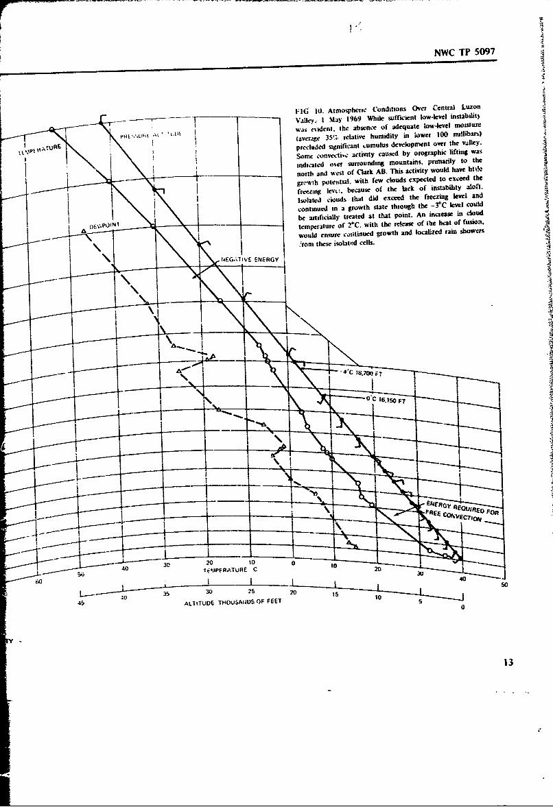
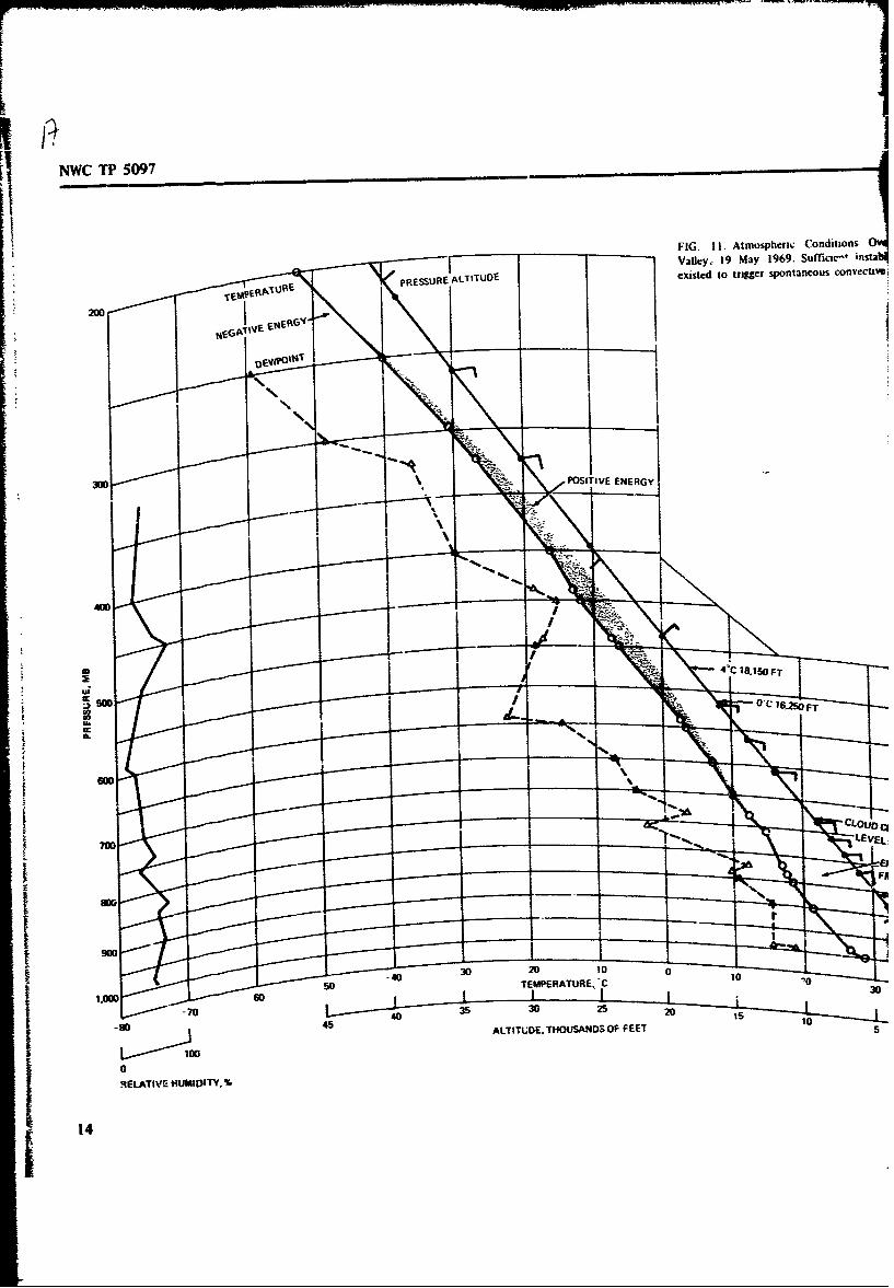
The intertropical convergence zone moves north.•,ird about this time. Cloudsdevelop along coastal hills and are mn4kedly affected by the presence of mountainsin the area (Fig. 9). The period of May and June, in which most of GROMET 11was carried out, has a gradual transition to the southwest monsoon. Atmosphericsoundings for typical dry and moist days during this transitional period are shown inFig. 10 and Ii.
Wide seasonal and geographic changes are reflected in the rainfall. Typical data
are summarized in Table 2. Cited cities are shown in Fig. 12. It must beremembered that rainfall in the Philippines is usually measured at the larger cities,mostly on the seacoast. Hence, the statistics more accurately represent rainfall frommonsoons and typhoons rather than that from cumulus activity.,
The effects of the southwest monsoon are clearly seen in the records fromManila and Baguio for July through September. Baguio has a strong orographicenhancement of rainfall most of the year. Dumaguete, on the east coast of southernNegros, lies in local and regional rain shadows, has relatively little rainfall by
10

NWC TP 5097
Philippine standards, and hz., almost no annual variation. On the other hand,Borongan, on the east coast , 'rfmr, develop. most of its rainfall during thetrade-wind epoch. Casiguran, on the east coast of northern Luzon, has a clearaddition to its rainfall during the short northeast monsoon.
A NATURAL RAINFALL PROCESS
During the period of the year in which a strong subsidence inversion coversthe archipelago, cloud growth is limited by the inversion, and clouds rarely reachaltitudes great enough to permit a vigorous coalescence process to take place,Because the condensation nuclei on which water droplets form are numerous andupdrafts are limited, the cloud droplets do not have a good chance to grow to sizes
large enough to permit high fall rates and effective capture of other drops.OL,'asionally, in one of the more important rain processes, one tower will rise
above the others and, by slightly greater vigor, penetrate the inversion layer. Thecloud, while growing, has a fine white appearance and after a while reaches the apexof its ascent, remaining well above the others. As the smaller droplets evaporate, theappearance of the mass changes to a wispy striated gray. Shortly after, cooled byevaporation of the smaller droplets, the tower falls rapidly into the mass beneath.The lower mass darkens as falling drop- .i ,- by incorporating smaller, more slowlyfalling drops, and a shower develops. No ice i. ,-.-,.?.ýary to this process. Indeed, theBergeron-Findiesen process plays little or no role in the clouds over the Philippinesbecause these chuds are usually ice-free even at altitudes to 30,000 feet.
CLOUD SEEDING TECHNIQUES
In general, cloud seeding involves locating updrafts in clouds and releasing
small amounts of s.eeding material into the updrafts. The seeding agent causessupercooled drops to freeze, releasing heat of fusion and setting in march a morerapid condensation of water vapor on the frozen drops than is possible on the liquiddroplets, with, of course, concomitant release of heat of condensation at a greaterrate. The heating makes the air more buoyant. and the updraft is increased, suckingin more air from below and causing increased condensation throughout the ascendingcolumn.
The techniques of seeding cumulus clouds, as used in GROMET I!, represent acombination of the best features of a number of seeding methods developed byNWC and by commercial cloud seeders.
Such cloud seeding is not difficult. the proper procedures can be learned by an
intelligent, instrument-rated pilot in about 4 hours and can be developed to a highdegree of skill after a week's practice. Specific procedures for handling the aircraftare given in a later section. Flight Procedures in Cumulus Penetration. SeedingIaegvn a scin
3 li

FIG. 8 Miss.on 2. 1745 1SF. Inversion capping air polluted by smoke. waith smallstratocumulus developing on inversion top. Cumulus growth under these conditions isunlikel). Photographed from 19.500 feet over Negros Island, looking north towardGuimaras Isand.
FIG. 9. Vsiayan Sea. Looking North From Negros. Note development of cloud; overWsands. Wind is light and variable-. air i- moist and unstabic,
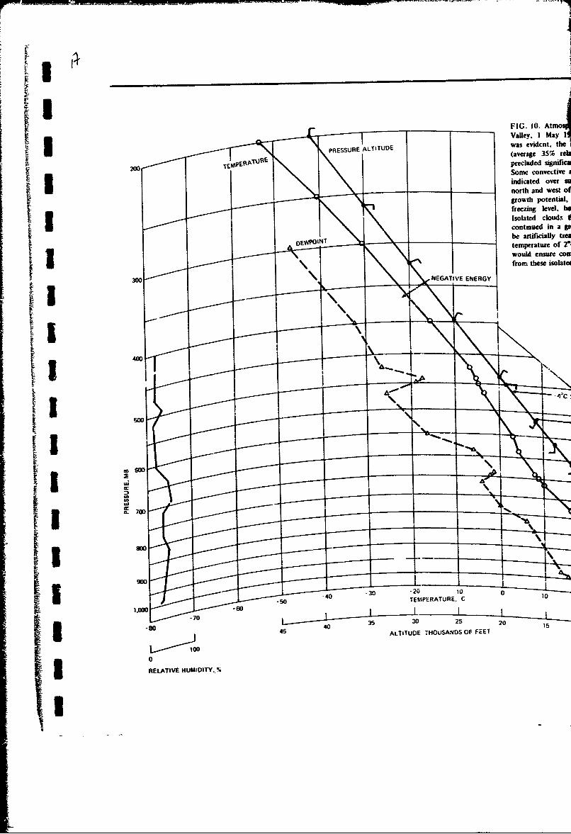
FIG. 10. AtmojU ~Valley, I May Ii
PRESSURE ALTITUDE was evidcnt, the
........... ..... .(average 3S% reb
200VEMERAUREprecluded sipniicaSome convec-tiveindicated over anorth and west olgrowth potential.freezing level, biIsolated clouds II I _ _ continued in a gibe artificially tza
DEWPI"Ttemlperture Of 2'W would ensuse coo
NEGATVE EERGY from these isolate
_ _O
OK S.
I8 4S 4 ALTITUDE THOUSANDS OF FEET 2
0I ~RELATIVE HUMIDITY, %
NWC TP 5097
I1:16 10. Atmospheric Conditions Over Central Luzon
Vle I May 1969 While sfficienat low-level instabilit)
~ .~' '~...swas evdent, fte absence of adequate low-level Moisture
P~ -' it At (aver wg 35',-, relative hum idity in low er 100 nullibar,)preciwde -Ignfnt .umulus development over the v~lICY.
Some convecti.'o activity caused by orographic lifting wasindiate o,.r srroudin mountains, piaytoth
north and West of Clark AB. This activity would have litQle
grc~wth poteistial, with few clouds expected to exceed the
freezing lev%ý. because of the lack of instability aloft.
Isolated clouds, that did exceed the freezing level and
continued in a growth state through the -3t leftl could
be artificially treated at that point. An incicase in cloud
- ~temperature of 2TC. with the release of the beat of fusioni.
would ensure cmnstinued growth and localied rain showers
I 4rom these isolated cells.
NEGJiVE ENERGY
O C 16-150 FT
-IG EOIE
40 ý Tf-.APFWNTURE C 2
3452 20
45AL~iTUDE THOUSAUOS OF FEET 00S -- -
13
NWC TP 5097
FIG. 11I. Atmospheric Conditions 0Valley, 19 may 1969. Suffictc-1 insta
PRES REALTIUDEexisted to trigger spontaneous convectlW~
300 POSITIVE ENERGY
a 4~C 18. 1 SFT
O'C 16W FT
.- ~- -CLOUDQ
_______ ______ EVEL.
SOTEMPERATURE. C 30
-70 25 2
-8 0 5ALTITUDE. THOUSANDS OF FEET 10
14 RELATIVE HUMIDITY. %14
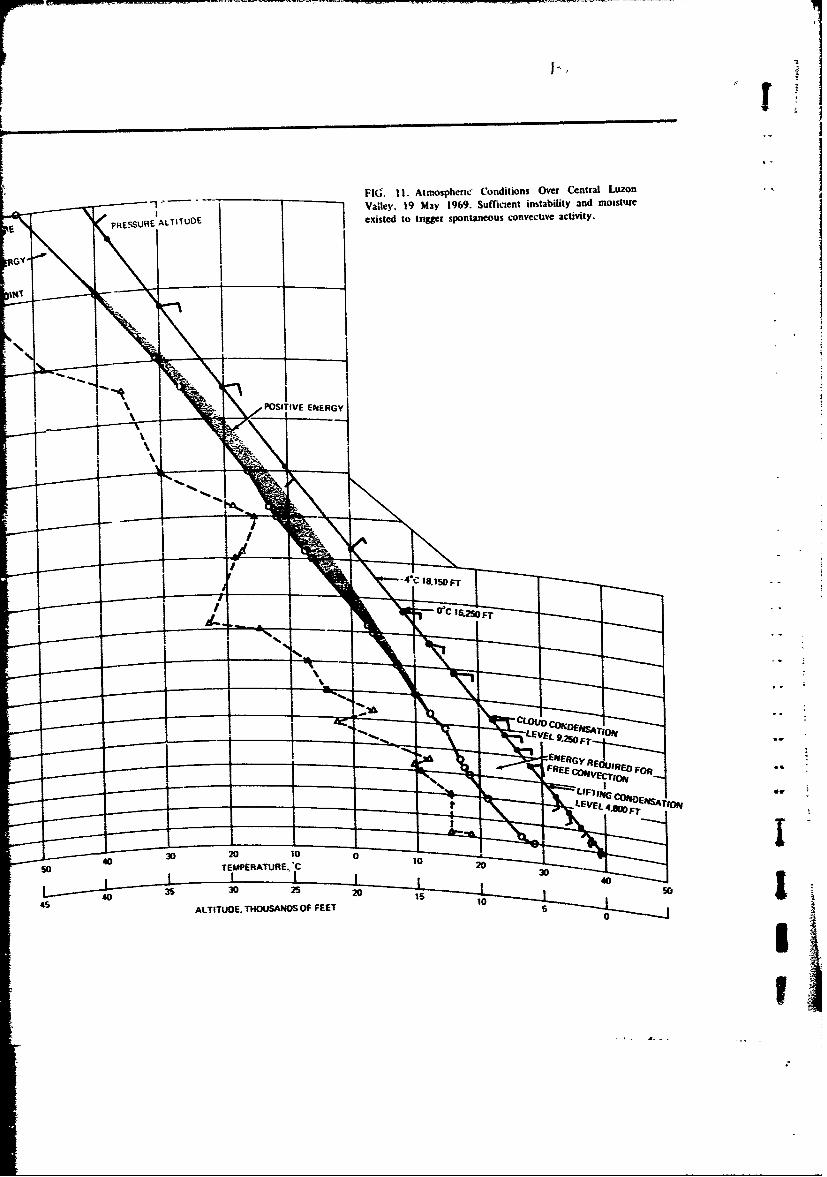
FIG. 11I. Atmospheicru Conditions Over Central Luazon
Valley. 19 May 1969. Sufficient instability and moistuzre
pHESSURE ALTITUDE existed to trigger spntaneous convective activity.
eGY
N.
POSI VE 1NRG
JI
t* -810F
.... ..
50 TEMPERATURE.. j
430210015 D0 5
ALTITUIDE. THouSANDS OF FEET 5

'I NWC TP 5097
TABLE 2. Mean Monthly Rainfall for Selected Philippine Cities.
Mean rainfall, in.
Period Manila Baguio Dumaguete D-wongan Casiguran
Tradewind: .Dec ............. 2.5 2.0 5.1 25.3 15.5
(Northeast monsoon)Jan ............ 1.0 0.9 4.5 25.3 7.1
(Northeast monsoon)
Feb ............ 0.5 0.9 3.1 17.3 9.1Mar .0.7 1.7 2.1 12.9 12.2Apr ............ 12 4.3 1.8 10.3 5.4
Transitional:May ........... 5.1 15.8 4.3 9.6 9.1Jun .............. 9 17.2 5.3 9.3 8.3
Southwest monsoon-Jul .............. 17.0 42.3 5.6 7.4 9.1Aug. ............ 16.0 45.7 4.3 5.7 10.9Sept ............ 14A 28.1 5.5 7.2 12.1
Transitional:Get ............ 7 15.0 7.7 13.0 13.1Nov. ............ 5.6 4.9 5.8 21.2 25.0
An-ual ........... 81.7 178.8 55.1 164.5 136.9
Nucber of
observed ....... 73 31 27 36 10
II
success is based on visual observation of the clouds, interpretation of the airflow illand around the clouds, and placement of the seeding charges so that the processescausing cloud growth are augmented. Figure 13 shows this growth.
Timing and restraint are important. Growing towers, recognizable by theirhard, cauliflower-like appearance. should be seeded just as they pass the - 3*C leveland before they have begun ;o stabilize or fall back. Restraint is necessary topreclude too rapid growth. which causes spindly towers (Fig. 14) to break off attP midcloud level and separate. and also to prevcnt overseeding to such an extent thatan outflow shield develops.
The most productive techaique is to cause neighboring clouds to join. tlherebyincreasing the areal extent without causing giowth to more than ah'•: 28,000 or30,000 feet of altitude. Fine examples of this are shown in Fig. i5 and lb.
The procedure of seeding the updrafts of clouds minimizes the energydissipated in turbulence and in changing momentum so t!hat only delicate treatmentis necessary. It is unproductive of rain to seed the whole cloud top because suchoverseeding induces too rapid growth. which results in disturbing the internal3 organization of the cloud and the air currents sustaining it "Fig. 17).

NWC TP 5097
20 -- I--- - --120~ 9125'
a 4
PHILIPPINE SEA
LUZON
15 BAGUIO CASIGURAN
SOUTH CHINA SEA
1 r
11IG. 1 2. Philippine Cities Cited in Table 2.
16 -
oi

T NWC TP 5097
WIND SHEAR CONDITIONS
While almost all seeding of GROMET It was done between thr -2°C and the-7-C level, the method of emplacement of the charges depended on the type ofcloud and the wind shear. Different wind shear situations required different5 techniques. Three of these conditions are illustrated in Fig. 18 under arbitrary
1categories Class A, Class B, and Class C clouds.
Class A Clouds
For clouds of Class A, where the wind shear was insignificant, the usual
approach was to select an altitude as near the -4 0C level as possible and ty overthe cloud top or penetrate the tower at that altitude.
Generally, when Class A clouds (Fig. 19) occurred as isolated towers, theywere seeded if they were more than 1 I/2 nautical miles in diameter, although somesmaller towers were seeded. The penetration technique was to approach the cloud
(Fig. 20) at a safe-penetration airspeed. with powe- and trim adjusted for level flightat a distance of several nautical miles from the cloud. From that time on. the pilotcarefully maintained the same attitude that had been set up after power adjustment.The aircraft was headed toward the ,co. and the course was adjusted so thatpenetration would occur in the most vigorously growing portion.
Before entry into the cloud, as the aircraft came within a distante of one to3 one-half cloud radius, a downdraft was usually observed. Just before entry the
data-recording apparatus was placed on high paper speed. When the cloud wasentered, it could be seen that individual turbulent rolls in the cloud were moving
t Iup, but that the air around the outside was moving down with respect to the1ascending roll. Some turbulence was noticeable, but the general up- and downdraftswere light. A few seconds after penetrztion a hard jar was felt. followed by a
sustained updraft, Continuing to fly attitude rigorously, the pilot used only the gyrohorizon and gyrocompass and ignored altitude and rate of climb. Once the updraftwas well identified, one seeding cart.,dge was fired. After 3 to 5 seconds the aircraftpenetrated the updraft core. The tore was easily recognizable because abundantliquid water in the form of large drops appeared on the windshield and there wasoccasional icing. Liquid water content jumped from less than I g!m3 to from 1.5 to5 gIm3 . It was found that if the amount of liquid water was small, say less than1.5 g/m 3, or if the u. sratt velocity was less than 200 ft/min, seeding did not resultin appreciable cloud growth.
Normally, the forward speed of the aircraft, about 200 knots true airspeed(TAS), carried the projectile into the updraft, core. If the updraft core wasadequately wide so that the liquid water content reading remained high for 10seconds after the first shot, a second shot was sometimes fired,
The liquid water content gradualty diminished as the plane flew through andpast the core: the updraft decreased slightly, until suddenly there was another hardjar, the aircraft began to drop to level flight, and the updraft changed to a moreturbulent regime, A few seconds later the aircraft broke into the clear, and asustained downdraft was encountered.
17

NWC TP 5097
(a) 1212 LST. Area on north coast of Mindanao lootingeast before seeding. Average clouds reach 18.000 to201000 feet,
(b) 1311 LST. Photographed from same position as viewia). same area after seeding: large, well-developedcumulonimbus dominates area.
FIG. 13. Examples of Cloud Growth, Mission 61, 18 June1969.
181

I ' iNWC TP 5097
(c) 1311 IST. Similar area, over Calabugoa Plains, near
.a* of (a) and (b) but not seeded. Clouds show only
- sholt gowth.
Sb
(d) 1345 MS. Sligtly more distat viem of (a) and (bi).
Cloud growth is continuing well.
lEIG. 13. (Contd.)
•-9
p1' _9

%I%(C I P 5097
• I
NI
FIG. 14. Mission 26, 15 May, 1538 LST, The isolated highcloud with virga was originally the top of the diffuse towerin the near center of the picture. After the top was seeded,it rose rapidly and pulled away and was blown to the rightby the wind, which increased sharply in velocity just abovecloud top.
- I?M
t
HIG. 15. Mission 5, 30 April 1969, 1550 LST. Mass of clouds grown together into alarge flat-topped storm.
220 i

NWC TP 5097
!I
iim
FIG. 16. Target 35c. 27 May 1%9. Zamboanga P-n"nsula. western Mindanao. Line ofclouds fused into single -mass 10 by 150 nmii. Growth limited to about 25.000 feet.Moderate to heavy ran fell for more than 3 hours.
I I
FIG. 17., Mission 14, 1329 LST, Southwest Panay; Top of Overseeded Cloud Blowing3 Off.
3 21

NWC TP 5097
-
Wa) Zero wind shear (CLass A clouds). (b) Wind increases with altitude (ClassB clouds).
(c) Wind decreases with altitude (Class C clouds). °
FIG. 18. Various Wind Shear Conditions.
Ordinanly, the pilot would fly the aircraft away from the cloud for about Iominute and then make a 90- to 270-degree turn to look back at the point of
penetration. In almost every case enhanced growth of the tower could be noted oncompletion of the turn. Such towers (Fig. 21) were not seeded again untilconsiderably more growth had occurred and adventitious towers at the sides hadbegun to develop.
By the time of reentry and repenetration of the updraft there was usuar-y Anotable increase in turbulence. in liquid water content of the updraft, and inupdraft velocity. In addition to the increase in liquid water, large parascles ofgraupel formed against the windshield and stuck, the water running off the dark icepart,-,es that sEd slowly along
22I

i NWC TP 5097
I.j-i i __--_.__ 4
IT
IFIG. 19. Cloud Over Trough of Philippine Fault Zone. Bicol Peninsula. Central towerseeded with one shot. Tower on right in collapsing state. Typical cloud from whichmoderate growth and limitEd rainfal may be expected.
Repeated attempts to measure ice nuclei in such towers failed, primarilybecause of rapid uptake of the nuclei by droplets or growth of ice embryos thereon.1 Nuclei were always found in clear air tests and around the periphery of seeded rainshowers at cloud base,
Seeded single small turrets of at least 1 to 2 miles in diameter grew rapidly-atrates of about 1.000 to 2,000 ft/min-and had some increase in diameter. Thegrowth would proceed for a few minutes. the appearance of the upper part wouldchange from a hard, cauliflower-like white mass (Fig. 22a) to a light gray wispycondition with the appearance of plucked cotton (Fig. 22b). This change was due toevaporation of the smaller droplets. which made it possible to see further into thecloud. Following a period of quiescence, the uplifted portion dropped back into themass beneath, and the portion below rapidly developed a dark appearance MFi9 23).At first a light rain would fall and then a rain shower.. producing about 100 to 500acre-ft of rain. wuld continue to fall for 15 t: 20 minutes with an intensity ofabout I to 2 in/hr (Fig. 24). Frequently, the center of the cloud would punch outcompletely after the rain and leave a ring of disorganized cloud around the seedingsite.
In general. single towers properly seeded would regenerate. usually upwind, andnearby towers would begin to grow. The mechanism for this is not clear, but itappeared that the enhanced downdraft and cold air around the tower was lifting thesdrrounding moist air like a micro cold front. Possibly. a counterrotating vertical cell
I(Fig. 25) was formed beside the cloud.
3 (23

NWC TP 5QQ7
PILEUS
UPDRAF7SSEEDIN
(N PORTION
ta) (b)
~~1
10) (d)
FIG. 20. Behavior of a Seeded Cloud in the Absence of Significant Wind Shear.
After one tower had been seeded, it was usually left to grow by itself, andattention was given to nearby towers. The more vigorous neighbors were selected,the smaller ones left alone, and seeding was then done in such a way as to causethe clouds to grow together. Once a sustained system was established, the largerclouds would often incorporate the smaller. which frequently were sucked infrom !he sides or fromn beiow along with whatever scud was present. Occasionally, aclear aureole would develop around a family of towers that had been consolidatedinto a vigorous mass.
About this time. the cloud base would begin to lower and widespread rainwould develop. Care was taken not to seed too much but to try to encourage
24

i NWC TP 5097
A, "M
IFIG. 21. Misir 4, 30 April 1%9.9 Northern Mindanao. Pho~agraphed from about9,000 feet. Seeded target is thin tower giroming into dry air in a weak windi field.
Typcal un.eeded lower douds surround seeded tower.
S1 ~growth only to the 25.000 to 28,000-foot level. Thle use of caution would prev'ent
6 forming a cumulonimbus cloud by ejecting material into the high wind shear thati was usually present at 30.000 to 35,000 feet, Figure 26 shows the development of
l such a cumulonimbus.
S~On occasion, tower complexes grew to heights in excess of 60.000 feet. as
S~measured by the weather radar at Clark. This growth (Fig. 27), while V•eclacular• : •and thril'ling, is not desirable, because shadowing of sunlight by the outflow shield
Ii can cause cloud growth to be discouraged in adjacent areas.In a Icev-wind field. amm unition -vpenditures in excess of 10 rounds per hour
did not result in more rain and usually deteriorated performance of the clouds.i Timing is extremely important in that one must arrive at the seeding pcint while
the clouO :s still growing. or at least before the top has begun evaporation and 1iI beginning 1to fall. Such clouds can occasionally be rejuvenated, but the prognosis is
generally poor. Seeding of puff, masses projecting from larger clouds with no4 substantial amount of cloud below them is f.Nilless.
I Seeding should be confined to updrafts because it is more effective in that
slight supe.rsaturations. larger drops, and higher liquid water concentrations exist.These ensure more rapid activation of the nuclei by diffusion and faster heat releasebecause of more rapid conversion of water to ice by contact nucleation of drops.
Seeding in downdrafts shxiuld be assiduously avoided. 'the nuchn ir n(,- s
active under the conditions of subs~luration. the liquid water content is less,.;;".ed
the mater13l is soon carried down below the freezing level where ice cannot form atI all. Moreover. it appears that meddling with the downdrafi can interfere with cloud
| _25

*• ~NW•(" iIP 501)7
II
(a) 1414 LST. Note hard. cauliflower-like appearance of seedabletowers. Tower to left was seeded with two Very pistol rounds. Towerto right has reached climax.
(b) 1425 LST. Seeded toter. looking west. One more Very pistolshot has been put into seeded tower- Seeded tower has climaxed atconiderablc height above nonsecded tower and is falling back.dropping virga. Unseeded neighbor has begun to regrow. This is anexampie of good target clouds and overenthusiastic seeding.
I-6G. 22. %1rss~on 11. Southern Zambaks Mountains Looking South.
26

i NWC TP 5097
II
II
FIG. 23. Mission 14. 1308 LST. Southwet Comer of Panay, Seeded toter collapsing.falling through scud, and producing rain.
I There are also dynamic reasons for seeding an updraft. It already has soaueupward momentum and is embedded in a circulation pattern associated with its rise.Seeding a downdraft tends to inhibit an established circulation pattern that in itselfmay help the total cloud activity. For example. seeding of isolated towers with afuzee by flying around the tower often results in rapid disappearance of the cloud.
* Seeding for rainfall augmen:ation must always be done so as to aid clouddevelopment by emphasizing the large-scale features of the circulation andminimizing activtty that would lead to dissipation of energy in small-scaleturbulence.
Class B Clouds
Class B clouds are those subjected to a mild wind shear of about _5 to 10knots over a vertical distance of a few thousand feet when the wind velocityincreases with altitude. These clouds lean slightly with the wind because the upperparts are carried along faster than the lower parts. Seeding of this type (Fig. 28) issimilar to that done for Class A single towers in a low or zero wind shear state.
In this case. however, seeding is not done in the exact center. but preferablyon the forward or upwind front of the cloud (Fig. 29). If the cloud is small.penetration can be done in any direction, but prudence dictates entry of largerclouds at right angles to the wind shear or penetration of the front portion only.
After it has been seeded, the front edge of the tower rises more steeply. and a
3 I27

N\(" jIP 5097
new cloud begins to grow upwind. The second seeding should not be done on thealreyid stimulated mass seeded first, but on the newer cloud forming upwind of the
previously seeded area. Frequently, whole new towers form, and these should be
seeded.Such clouds can easily be made to grow upwind but rarely downwind Lateral
growth is frequently easy to bring about, and isolated leaning clouds of otographicorigin can be joined together to make a linear array of clouds. After a few hours,
liowever, such arrangements usually develop into one o0 more isolated cumulonimbus
clouds that dominate the scene.While successful seeding of leaning clouds requires a larger cloud mass to begin
with than in the case of vertical towers, the leaning clouds can easily be made to
produce abundant rain. Care must be taken to prevent development of
cumulonimbus clouds. which results in a narrow zone of very heavy rain and
increased wind.
lat 1240 LST. The beginniag of a rain shower, I mile east of the seeded turret. At1250 the %%eather Officer in the aircraft above reported, "3.500-foot growth in 10minutes: mass much larger. towers beginning to build adjacent to main cell;considerable rain beneath.-
FIG-. 24. Missions 12 and 13. 6 May 1969. Sequence of shower development overtown of San Pablo. southern Luzon. At i230 LST a small cloud was seeded with oneTB2 round at 17.800 feet. -2.5'C. by flying over *he highest tower. At 1251 a secondTB2 was placed 3 miles west at 20.700 feet. -8.5*C. The shot poirts w.re slightlynorth of San Pablo. At 1313 a third shot was placed just south of San Pablo at19.600 feet, -6 C. During this operation one aircraft remained above, the other belowthe cloud. There was only a light wind of a few knots from the west at ground level.The •ire of the cloud can be estimated from the shadows.
I

NWC TP 5097
(b) 1250 LST. The ramn was now a light shower, in places moderate, as visuallyestimated.
1L
I!
(c) 1300 LST. Same shower was raining heavily and was somewhat increased in size.Note the larger shadow area in each successive picture, Radar runs gave rain ratesbetween 0.5 and 4.0 in/hr. Duiing the time of observation, the rain shaft drifted s;ome5 nautical miles to the east.
FIG. 24. (Contd.)I: -9

NWC TP 5097
WIND
DOWNDRAFT ENHANCED
BY CLOUD GROWTH
SEEDED CLOUDt
INDUCED UPDRAFT LEADING
TO CLOUD FORMATION
FIG. 25. Possible Mechanism for the Regeneration of a Seeded Cloud.
Well-developed cumulonambus in a good wind shear regime can be sometimes
cut off by very heavy seeding in the main trunk. Penetrati3n is at right angles to
the wind shear, and a seeding unit i6 dropped every 5 seconds. Excessively rapid
growth results. the central column narrows and breaks off: and the anvil blows
away. The underlying cloud collapses and does not immediately regenerate. Updrafts
of 2.000 to 4.000 ft.min have been noted in these shafts following seeding. It is
supposed that the increased vertical flow results in induction of excessive amounts
of drier air from the sides. and that the subsequent evaporation and cooling cause
destruction of the cloud.Occasionally. one encounters lines of towers arranged along the wind (Fig. 30).
These are best seeded by proceeding as far upwind as one wishes to develop rain
and seeding the nearest tower, The seeded tower grows. and its growth is followed
by development and growth of the towers downwind from it. By working back and
forth along the system. several clouds may be joined into a continuous line. . -
Seeding rates on leaning clouds are about the same or slightly higher than on
vertical towers: 10 units per hour is a reasonable expenditure rate.
Class C Clouds
With the onset of the southwest monsoon. a situation was frequently observed
in which the wind velocity decreased with altitude. The upper part of the cloud
moves downwind slower than the bottom, and the cloud appears to lean into the
wind rather than with it. Clouds shaped by this kind of reverse shear are labeled
here Class C clouds.This situation can be foreseen from pilot balloon forecasts or recognized by
noting smoke near the ground or waves on water.
30 i

NWC TP 5097
I'
(a) 1445 LST. Rising tower was seeded at 1448 at thepoint indicated. The tallest tower was not seeded becauseit was too late in the growth cycle. Cloud is overshoreline in southwest corner of Lingayen Gulf, lookingwest.
i
bI Ib) 1459 LST. Close-up of seeded area. Seeded portionhaw grown up to original high touer.
FIG. 26. Devclopment of Cumulonimbus. MiNion 8. 3I I May 1969.
II 31
r4

NW( TP .5O97
(c) 1501 LIs. Seeded area has
increased in height above its neighbors;old tower in (a) has begun to fall, andits base has pulled up. Cloud is nowbegnning to rain.
(d) 1507 LST. Seeded tower i' now well above all
neighbors; top is beginning to pull off and is being blown
over neighbor to left.
FIG. 26. (Contd.)
32
I NWC TP 5097
IIIC
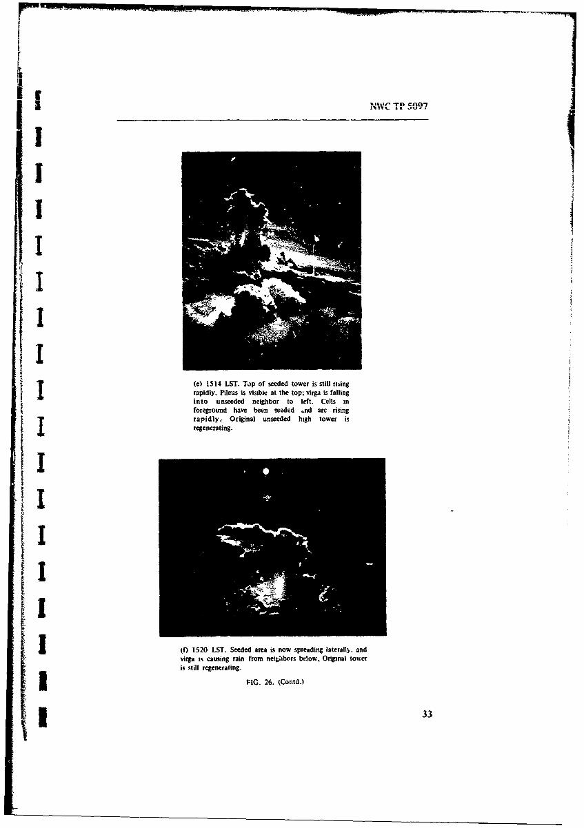
(e) 1514 LST. Top of seeded tower is still nmingrapidly. Pileus is visible at the top; virga is fallinginto unseeded neighbor to left. Cells inforeground have been seeded .nd arc risingrapidly, Original unseeded high tower is
S~(f) 1520 LST. Seeded area is now spreading laterally, and
virga i% causing rain from nei~tbors below, Original toweris still regenerating.
I33II

(g) 1548 LST. Seeded tower has now grown a prominent,hield touer:ng above nearby clouds. A neu tower has
begun to gro% to the left.
FIG. 26. (Contd.)
As in the case of Class B clouds, seeding should be don, on the upshear side
of th, cloud so that the coalescence path of old cloud and new growth is a
maximum. For Class C clouds, however, the upshear side is the downwind sidc.
Again. seeding may be by penetration as in Fig. 31. or from on top of a risingtower. A properl' seeded cloud in a reverse shear situation is shown in Fig. 32,
Figure 33 is an example of the complex cloud formatior. sometimes associated withthis wind condition.
FLIGHT PROCEDURES IN CUMULUS PENETRATION
The dangers of penetrating cumulus clouds are great for a pilot who does not
know how to do this. On the other hand, penetration can be done quite safely and
without serious difficulty if a few rules of good airm.riship are applied.
"Tih difficult% arises i I part from attempting to fly a combination of visual
and instrument flight. As a pilot approaches a cumulus, he has a tendency to raise
the ns,, either because the vis,.'al horizon now becomes apparently the cloud topo- because the cloud is rising. This results in a reduoed airspeed. The airspeed can
be reduced to the point that a high-speed stail is possible in the presence of
turbulence. The loss of airspeee is cortected by dropping the nose and adding power
until the rate-of-climb indica:or returns to near zero. By this time airspeed is often
exc.'ssive and heading may be los'.Subsequent to entry. primary reliance on the rate-of-climb indicator leads to
problemns. because this device has a built-in time lag and often tells what the plane
34

NWC TP 5097
Ilk
FIG. 27. Massive Cumulonimbus Developing Ovei Central Luzon.
TA
II.2.Msin2 9Arl1 9 Nr -sIln.Tpcllaigcodi hafil ihwn nraigsihl ihattd.Udat r on ln ih-tn(uwid ede.dwdat olf.-iaVa-- flqi wtrhsbgnt om
filod iha beensedd inceasing slightl ait arslttude. wipdrwtarc proundiloe ishteepened.
Neu low towers on night can be expected to grou.
ii 35

NWC TP 5097
SEEDING * /EEDEO AREA
0 c• (
(A) (b)
SEED NEXT
'Ii'(d)
F-IG. 29- Beharior of a Leaning (loud in a Uniform. Gentle Wind Shear.
was just doing and not what it is doing at the present moment. This leads to wideexcursions in airspeed and extreme changes in pitch. The "instantaneoue'rate-otf-climb inrcators are better, but these, too. can lead to an unstable conditionif too rigorously followcd.
The techn:que taught to almost all instrument-rated pilots works well. Uponapproach to a cloud, power and trim are adjusted so that level flight is establishedat a safe speed for turbulence. This safe speed is usually 1.4 times the stall speed inthe condition in which the aircraft is being flown. Foi the WC-130s used inGRONlET i1 safe speed is about 170 knots indicated airspeed (IAS). and for aCessna 210 or 337 it is 110 knots IAS.
Upon establishing this speed and trim. the pilot then proceeds to fly entirelyby use of the gyro horizon and gyrocompass. Airspeed is used as a backup. and thealinmeter and rate-of-climb indicator are ignored. If the gyro horizon should fail or.in extreme circumstances, tumble. rdliance should then be placed on the rate-of-turn
36

NWC TP 5097
FIG. 30. Mission 38, 31 May 1969, 1458 LST, Over Mt.Arayat and Manila. Looking Southeast Along SouthwestFlank of a Line of Clouds. Cloud in center is well seeded
and growing. Next seeding points are indicated. The massis being merged into a larger system. The cloud has begunto dominate the local circulation and is sucking inmateria! frown the south on the lower right. The wind at
seeding altitude is light and into the picture to thesoutheast: at the altitude of the shield it is blowing tothe south. Tht line of clouds is now o-r 30 miles longand 5 miles wide over the south Central Luzon Valley.
I indicator, airspeed indicator, and gyrocompass: and operations should be terminatedas soon as possible.
Ideally. an angle-of-attack indicator should be used and a constant angle ofattack flown., but this instrument is generally not available.
Response to changes in pitch and bank should be rapid but not overcontrolled.If this procedure is followed, the rate-of-clin'.b indicator w'ill give a good indication
- of the velocity of the up- and downdrafts both inside and outside of clouds. Thisinformation is vitally needed for effective seeding.
! I Changes in altitude during a 2- or 3-minute penetration are not consequentialunless the aircraft is flying e-cr mountains or has a poorly functioning oxygensystem. Icing occurs, but if pilot heat is us iitle harm results. The ice evaporatesrapidly after the aircraft leaves the cloud. I the ice does not evaporate, a descentS0to the -2°C level will usually cause it to fall off. especially in a high-airspeeddescent in which aerodynamic heating helps with the melting.
Turbulence in a well-grown cumulus congestus in the Philippines averaged i.5g. where stable conditions are taken as 1.0 g. The extreme noted was 2.1 g on oneoccasion when pilotage added to the problem.
The prudent pilot will so plan cloud penetrations that a pr.)pLrlv chosen pathwill bring him clear of other clouds upon flying out. To ,!:,- end. a curved
w37

NWC TP 5097
SEED IN G SE D D k Eoc ( ýE
"0"•
1- O1N I
SEEDE AREA
-c
Ia) . .. ('bi
P... , (d)
FIG. 31. Behavior of Seeded Cloud in Revense-Shear Wind Field.
trajectory is sometimes advisable- Penetrations should be planned so that exit ispossible within I to 2 minutes.
Penetration at altitudes between 8.000 and 16,000 feet leads to the worstturbulence both inside and outside a cloud. This region should be avoided unlesslouJ physics data are needed.
Penetration along the wind shear in a cumulonimbus should be avoided, butpenetration in small cumulonmbus at right angles to wind shear can be made safely,especially if the penetration is only a partial penetration.
Seeding beneath cloud3 can be done to good effect, but in the Philippines itwas not practical owing to terrain and low cloud base. Cloud bases lower followingsuccessful seeding. and it is unwise to be caught in high terrain under these
38

NWC TP 5097
FIG. 32. Wind Is Wlowing to the Right. Thc growing tower to the right was seeded.Rain is failing fron, the main mass of the cloud. Seeding in the highest part uouldprobably result in separation of the overhanging bulge.
FIG. 33. Complicated Structure at (loud Top Durinsv, Re, erse-Shear Situation.
39

NWC TP 5097
condiittionl because the only alternatives are to exit by visual flight rules under-marginal conditions of visibility or to attempt an instrument climb-out with no clearidea of %% hich % Ay to go.
With turbochlarged aircraft at altitude, it is inadvisable to slow the aircraftbelou 40 knots, because ram air aids the turbocharger and too slow an airspeedmay result in too rich a mixture, causing momentary engine failure.
FACTORS AFFECTING SEEDING SUCCESS
High Wind Shear
IW the wind shear is too severe (Fig. 14). or if in the case of an orographiccloud, the wind is too strong, seeding may not result in much rain.
Figure 3'4 shows a situation in which a weak, mechanically sustained cloud ina low-wind field is -ubjected to a high shear, that is 20 knots or more within 4 fewthousand feet just abov! cloud top.
Layered Clouds
Frequently, a drier layer of air develops between the lower moist air and ahigher layer of moist air, Under these conditions clouds may grow through the drierlayer, thinning out ii the middle (Fig. 35). and widening again at cloud top. Thissituation requires great care to make seeding work. Too much seeding can cause thetowers to separate in the midsection. However, slow. careful seeding can make thesetowers grow- Such clouds were frequent on central Luzon. just north of Manila.
The strategy that seewej to work best was to go to the middle of a field ofsuch clouds and select several ot the larger. seeding them and causing enough growthup through and drizzle back down through the dry layer to humidify it. Afterabout an hour of such activity. the middle air would be adequately moistened topermit cloud gre ith and normal seeding.
Occasionally moist layers below and aloft with reasonably moist -ir. say 50 to--- r relative humidity, between them would form a stratocumulus deck below and ahigher stratus above. Seeding of rising towers in the lower mass would result ingrowth. with the towers penetrating the upper layer. Usually the towers rose abovethe upper layer and then settled back on the sides and spread out, althoughsometimei they reached considerable altitude following penietration. Figure 36 showsthis effect on Luzon.
Orography
In the Philippines clouds tend to form over hills or chains of hills. Suchclouds develop earlier in ,he day than clouds over lowlands, and even on the
40

NWC TP 5097
I'SEED)N2 1
(b)
BASE ASCENDS
FIG. 34. Effects of Seeding in Rapidly Varying Wind Field.
generally cloudless days some orographic clouds worthy of attention do form andcan be successfully seeded.
When oc-agraphic clouds occurred, they were worked, on the assumption thatsome rain was better than none. even if it fell ojily in the hills. It soon e'veloped.however, that when these clouds had been vig:)rously seeded and grown. thedevelopment of clouds over plains and valleys appeared to be suppressed. This wasespecially notable in central Luzon and on Panay-
Luzon. The central valley of Luzon is an alluviated graben about 40 mileswide and 60 miles long bounded by the Zambales Mountains on the west and theSierra Madre Mingan Mountains on the east. Figure 37 is a map of central Luzon.
A possible explanation for cloud suppression over the Central Luzon Valley isshown in Fig. 38. Air that has been uplifted over the hills descends over the valley.
! l 41

NWC TP 5097
SEEDING
"�(OMOISTER AIR
(b)FIG 35. Cloud Growth Through Dry Layer.
with consequent adiabatic heating and destruction of the clouds in the valley, Under
these c nditions waves on Manila Bay and on Lingayen G.If indicated a seaward
drift ot air.I, on the other hand one waited until some clouds had formed over the
valley,, usually to the south of Baguio. and then seeded those, an influx of air from
Lingayen Gulf was noted and a sea-breeze front consisting of a line of clouds acrossthe valley gradually formed some 10 to 20 miles inland, Once these were worked,the whole valley began to develop cloudiness, and a second sea-breeze front began
to form north of Manila.Panay. The island of Panay frequently has clouds over the .,orth-south chain
of hills on the western side of the island. If these were seeded first, development of
clouds over the central and eastern portions of the island did not take place sorapidly as would have occurred naiurally.
On days of very low wind the clouds over the valley were well developed
before those over the hills dominated the circulation. On such days clouds usually
appeared first on the southwestern and southeastern corners of the plains and thenon the northwestern and northeastern corners, over some low hills.
By carefully avoiding the wcstern mountain barrier and seeding the innermost
members of the cloud ,-ystems. it was frequently possible to cover almost all the flat
lands of Panay with rain. Once such an extensive system started, it wasself-sustaining and rainfall continued for hours. At times rain rates between 3 and 5
itnhr were observed over large portions of the island. with lesser intensities between.,
Air Pollution
Almost eicry day in the vicinity of Manila and on many days elsewhere it was
difficult to start cloud growth by seeding, and rain was scant. Near Manila the cloudbases were higher. generally around 5.000 to 8,000 feet; updrafts were less vigorous;
42

NWC TP 5097
T
. J
FIG. 36. Mission 6, 1 May 1969, 133*1 LS, North of lba on Luzon. Seeded cloudsgrowing from lower scud through a drier layer and spreading out in all directions in a Ihigh-level inversion. Clouds lack buoyancy to penetrate farther. Clouds originallyseeded at 17,200 feet; photographed fro.-m 19,900 feet.
liquid water content was lower. and droplets were smaller, at least as indicated bythe wetting of the aircraft windshield and by icing.
It is the opinion of the authors, an opinion corroborated by Ref. 4. that this
effect was the result of air pollution, and that air pollution was indeed a major
cause of the drought. The air was continually being polluted by the burning of
enormous amounts of brush, grass, and slash from logging operations and by the
i" I burning of sujarcane wate.An appeal was made to Philippine Goernment and Sugar Institute officials.
with the result that the burning was stopped completely in some areas and confinedto certain scheduled periods in others. In a short tine the visibility improved, cloud
bases lowered, droplet sizes increased, and seeding became more productive.
Seeding Frequency
At the beginning of GROMET 11 clouds were not widespread and the search
for suitable target clouds was difficult. After a few days of seeding the air becamemore humid, clouds formed more readily, and natural rainfall was more frequent.Wind velocity was low and wind direction was quite variable, so that the humidified
air remained over the archipelago. Evaporation from the ground and transpirationfrom plants increased.
Had a statistical experiment of "controlled" or "one-day-on. one-day-off"
seeding been tried, the apparent effects of seeding would hae been a rapidly
43

NVVC I P 509)7
7-;yb/v
FIG. 37. Central Luzon.
DESCENDINGAIR
SOUTH ZAMBALES MT. MT. ARAVAT SIERRA MADRE PHILIPPINECHINA SEA MINGAN MT. SEA
I K. SX'. (wss Scxtton (If Central WLon. Showing Suppression of Clouds Oser Centralj.itle
44

NWC TP 5097
decreasing seeding effectiveness, while in reality the overall precipitation would haveincreased.
From experience we found that I day of heavy seeding over the VistyanIslands was more than enough for 3 or 4 days of rain, therefore, flights werescheduled less frequently, the same areas being revisited only every third or fourthday unless some operational requirements made it more convenient to ieturn.Because of the permeable soil. most of the water would soak in quickly in I day,
-" and the soil would soon again be dry,
TACTICS OF A TYPICAL MISSION
Mission 47 on 7 June 1969 resulted in good cloud gromth and extensive rain,L I and is a good ex-imple of the technique employed. Table 3, the day's seeding log,shows the details, After takeoff from Clark AB at 11!0 local time (0310 GMT) theGROMET team proceeded to Palawan, where a high overcast with bases at 19,000feet made cumulus development unlikely: the aircraft, therefore, was diverted to theVisayan Islands. previously agreed upon as a secondary target area and arrived at the
southwest corner of Panay at 1300 local time.The weather officer reported cloud coverage as 2/8 cumulus with bases at
"2,000 and tops at 8.000 feet. 2/8 cumulus with bases at 2.000 and tops at 20,000feet. and 5/8 cirrostratus between 22,000 and 25.000 feet. This cirrostratus waspatchy and contained no ice. At 19,000 feet the outside air temperature was -5°Cand the wind was estimated as 120 degrees at 20 knots, although it was probablyless.
An isolated growing tower with some lower scud just east of the hills wasS Jt.seede. (point 2. Fig. 39) at 1302 at 20.300 feet at -80C. Another much smaller
isolated tower (point 3) was then seeded 7 minutes later, Five minutes later, at7 "1314. enough new growth had developed around point 2 to permit seeding at points
4. 5, and 6 in separate towers. Seven minutes later new growths haa appearedaround point 3 and had grown enough to permit shots 7. 8, and 9 in quicksuccession into separate towers that had grown to the 19.500-foot level. These twocloud families, designated A and B in Fig. 39, were left to grow by themselves, andGroup C to the north, consisting of two towers (points 10 and II). was seeded 13minutes later. Group D. with tops only at the -2.5 0C level, was just starting up andwas seeded next at point 12. Group E was seeded next with one shot at point 13.followed by a return to D (point 14). where a rapidly growing cell was seeded at-40C.
Six minutes later, Group F (points 15 and 16) was seeded. arui the aircra"returned to G (point 17). by now growing in an area where only low clouds hadbeen noted before.
Group D was filling in nicely, and point IS was seeded next., some 25 minutesafter the first attack, in an effort to pull the separate clouds of Group D together.
They quickly merged, and F was struck again (points 19 and 10). followed by point11 21 at the border of H1. Next. t'vo rapidly growing towers in Group E were merged
45

NWC i p 5097
- ~- ' -T
-L--ncoq~zz
0
o 0Is
C - I I M
0,- - - - - - -I - - - - - - - - - V
'w a
I -1-1 -9 - I I Zo
oU -- v I a I % A
o z 7- ot
2 -44 A. AV - m'Izi 0t

SNWC TP 5097
1507
-- r
|r' Il I
, I
p j 1 _ _
_ _•• Iu ,,_" - - -
, _ _ I
Ir o' "ro •
ft t o! , •
az4 aa.
_ i i z
Il •li-- , r-
>• I I I ______,__
IC -- = -
% .. I%.
a .. -i- -
*q' * 4 0
4 q v'. ,) w ,~--. - -,- I -- )•...7
•- • - - -- , ..L --- -- , • ' ! -I •
I 1. :

NWC TP 5097
iii1' 1: I 1 iI | -•
to~t
I IiI I I t-I-1--1-- -.¾--E
tI-! I
- m _ _,i I' V,.lw •
r,- r .. . . .. . -l 0, =Stt " I Il)IE .I t , / II
I j t I, i
t'/
- iI~-~ I
0 oi Q1 #I vq , C4
-'too 0iRI ,___, I --1-i-
_l3 i i.•!I,,' .,.I•E m'lrn.o.o o, ." "t-- l I'ii'• r• ,i!-- i ,i!o.a;i
OD ' I d
C-1~* r- -1
4. _ 1, IM:a 40 Q. 0
Gaa -
48, i o o-,I -
II_:'1 _ • •1,• !I ," • l , - ; °ill I a -I
• ,i •l • " -l • ",, ,,
I_ -. I I• _!
4I I I E
Lii i I
I5II -

NWC TP 5097
~ ~ ~sUfOYAN SF4 A- '
VI';AYATJ ',f A
nPIA 18*N '2 -C.
c6
VV
'0 --
PANAYTLA GULF
FG3.Target Locations, Mission 47., June 1969. Symbols such as 10-50 indicate wind
dljection (105 degrees) and wind speed (10 knots). 4

NWC TP 5097
fl~o~~ng ,%holt, 12 and 23, and 1) was extended northward by shot 24. Shot 25 atII .ompleted the seedimg in ti-c iorthern p-rt of the island.
By now tite whole of1 the northern mass had merged into a veritable wall ofcloud, with tops to about 30.000 feet. A rain rut, was made under the group.lleavy precipitation was encountered all a.ong the line. Lquid water content in therain shaft reached 3 g!m 3 as measured on the Johnson-Williams meter. Rain rate wasestimated at I to 3 in/hr. On climb-out Group G was reseeded at point 26,extending the southern sector to the east. The clouds there had by then also growninto one large mass.
Because both cloud groups were raining well, the aircraft departed Panay andarrived at northern Negros at 1510, where three points (27, 28. 29) in Group Iwere seeded. These %ere small clouds that grew well and merged into a largecumulus congestus. At 1530 the crew left Negros and worked central and southernCebu. where a collection of towers was grown into a line of cumulonimbus byrepeatedly working back and forth between various members of Groups J. K, and L,points 30 through 45. These merged within 25 minutes. and work began farthernorth on Cebu at points 46 and 47. Group M developed slightly. merged. and rainedbut did not appear promising. At 1619 one more shot. at point 48, was put intoGroup I and a new group. N, was seeded with four si;ots (49 threigh 52) over a12-minute period
At 1637 the team departed Negros and climbed and released a dropsonde (Fig.40 and 41 ). By then the air Y. is almosi saturated to 20.000 feet, probably from allthe cumulus activitv.
The clouds or, ?anay (Fig. 42) were still a formidable wall across most of theflatter parts of the island when the aircraft returned to base some 4 hours afterstart of ;%,eding. Total rainfahi on Panay on this day from seeded clouds wasconse-aatively estimated as 160,000 acre-ft. Assuming 4.500 square statute miles astl.e area of Panay,. thi means an average rainfall of 0.7 inch over the whole of theisland. That more may have fallen locally may be inferred from Fig. 43. takenduring the rain run made early on this day.
PROJECT FINDINGS
Detailed tabulatioic of the 62 missions conducted during the course ofGROMET II is given in Appendix A. Tables in this section summarize some of theinformation in this Appendix.
Generally. rainfall intensity w%-as estimated visually, but in a few cases theWeather Science. Inc.. rain-rate meter was used to measure rain intensity.
If one could see through the rain shaft to objects beyond, the rainfall wascalled light (L), If one could recogniie topographic features at least a mile into theshaft, it was called moderate (M). If one could see int, the shaft le-3 than a halfmile. the rainfall was called heavy (H). These estimates vary, of course, with
50

1 200
* 1 ~300_
I ______.TU AL__
In
m ow
* 100
03 ý2
3 ~RELATIVE HUMIDITY.

200
T7EMPERATURE PRESSUSJ
Lu DEWPOEINTj,.
.........
TEMPERATURE. 'C
10D ALTITUDE. THOUSANDS OF FEET
RELATIVE ,4UNIIDITY. 'ý;

NWC TP 5097
FIG. 40. Missicn 47. 7 June 1969. Dropsonde Data
Atmospheric condition% over water areas surrounding ýhe
Visayan Islands. The dropsonde was released at 1645 LS','
approximately 6 miles northeast of the town of Bacolod on
Negro% Island. Permission was obtained for the release ot
dropsondes over water area% only. and unfortunately. the
only land-based rmsinsonde station in the Philippine Islands
is at Clark AB and is too disant to be useful here. The
dropsonde indiiated that the traverse of air fromi water to
land areas would certainl) give rise to considerable
convective activity The low-lesel streamline anal)sis
indicated a southwvest tlow over the Visayan Islands..
becoming south-southeast further nortl- over Luzon. A~ith
this tlow it is obvious that the hwher terrain of southern
and western Panay and that of Negros were most tavored
for widespread rain shower activit).
TEMPERATUR RESRE ALTITUDE
DEV&OINT&.
POSTIV ENCIOE FO
LEVEL IDEttSAT,0
-40ER~ TEPRAUE I
EE C5 20ICU'I o
ALTITUDE THOUAND OF FEETTO~
51

NWC TP 5097
7 0 0 T E M PN E G A T I VERE SEUE RGAII
300 WE,ENI
400
6000
700
REAIV UMDTY
...5..........2 ...

I
FIG. 41. Clark AB, 7 June 1969. The ,tandaid Clark ABrawinsonde at 1400 LST permits tompirion of condition%over Central Luzon Valley and GuimAra% Strait. Althoughthe temperature profile% are quite similar. the moistureprofiles are significantly different, with the Clark sounding
Y reflecting a much drier atmosphere Significant cumulusdevelopment by convective processes is not likely over theCentral Luzon Valle), because of the lack of low-levelenergy at this hour of the day-, howeer., considerableactivity could be expected over the surrounding higherterrain where the major factor is orographic lifting. Thiscomparison is presented a- an indication onl,, with distankeand chanes in flow patterrs ilegating any positiseinterpretations. Note that Mission 46 was conducted o.erLuzon on this date.
WEAK POSITIEENERGY
-4'C 20.000 FT
-- WEAK POSTE ENERG
L LOiD CONDEI•AVr!.,
""El. 11.000 PT
.._.._..._ _. .t ...................
-LIFTINGCOLEVEL 0 0 -SATIO
ENEF F 4REOUIARFO
OR R 6CONVECTO
20 100EMPERATURE. C 20
11 203030 25 20 15405
DETHOUSANDSOF FEET 105
0
,s • - ---.• _.. I s

NWC TP 5097
I!
FIG. 42. Wall of Clouds Over Northern Panay at Termination of Mission 47.
illumination and the difficulties of seeing beneath the cloud and so are not entirely- - reliable,
Correlation of these visual estimates with the few actual measurements taken
-. indicated that light rainfall corresponded to intensities between 0 and 1.0 in/hr.
-. moderate to rainfall between 1.0 and 2.0 in/hr, and heavy to rainfall in excess of
2.0 in/hr (Table 4). Tables 5 through i1 summarize the more complete tabulation
of all GROMET If missions given in Appendix A. For Tables 5 through i1 and
.. Appendix A the following key applies to column headings:
L Light rainfallM Moderate rainfallH Heavy rainfall
No No rain
No(V) No rain from target cloud. but rain in vicinity within 10 nautical
miles
U Unobserved
For the luantitative estimate of rainfall in Appendix A and in Tables 9
through 1I. the following values are used:
L 0.5 in/hrM 1.5 in/hr
H 2.5 in/hr"These estimates are used to describe cloud systems or targets. which may be a
single cloud, cloud complex, or several such that occurred in the same general area
,j and responded similarly to treatment.
*1 53

NW( TP 5097
FIG. 43. Mission 47. 7 June 1969. Postseed. Well-wetted paddies and fields on Panay.Rain in distance., dark cloud base above.
PRESEED AND POSTSEED RAIN INTENSITIES
Table 5 shows that of the 326 cloud targets worked, 258 were not rainingbefore seeding. and only 74 of these were within about 10 nautical miles of rainingclouds. After seeding. rain was observed to fall from 266 cloud systems.
In four cases rainfal! intensity decreased after seeding, and in 36 no significantintensity change occurred. Twenty-three cases did not result in rainfall. In 37 casesclouds were seeded in passing. and rainfall that may have fallen was not observed.An increase in rain intensity occurred in 249 cases.
Table 6 expresses the data of Table 5 as percentages. Of all the cases seeded,rain did not fall or was reduced in intensity in 7.4%. An additional 4.9% wereunchanged in intensify class, and 76.4% rained harder after than before seeding.
Table 7 expresses all cases in percentage of the preseed class. The low value ofpercentages for M in the initially nonraining class is probably an artifact of theassessment process whereirn observations reported as LM were reduced to L andthose observed as UH were auemcnted to H_
Of 23 cases witlt, no postseed rain (Table 5), 5 cases coulti not have beenexpected to work because the clouds were too low or too warm. Table 8 combinesclasses No and No4V). eliminates U of Table 5, and is corrected for sevenquestionable cases in which rain was not reoorted following seeding. These dubiouscases are explained in a %`otnote to Table 3. In this table 6.4A% of the cases (No) inwhich the Joud was not raining beforehand were unexplained failures.Mismanagement in terms of seeding too late or overseeding, ordnance misfire or
54

NWC TP 5097
TABLE 4. Measured Raini Rates Used To Quantify Observer's Rain Intensity Estimates!a
Average b Length of vrTam . A e Length ofoTretno.rain rate, in/hr Irain run. nm rain rate. ,n/hrb rain run nmi
Observer's Qualitative Characterizatior: Light Heavy
12a ... 0.05 1.8 25e ,.. 13.4 10.90.2 4.2 1Od ... 3.92 1.7
0 (0.3) (2.1) 4.9 1.9) 10.1 ) Observator,s Not Characterized
.. (2.4) (,0.2) .
12a .. 0.4 1.3
1.1 1.3 0.6 1.9(1.8) (0.2) 0.6 1.4
- 19a ... 0.2 2.0 (1.4) (0.3)
24c ... 0.9 1.5 1.0 028Light to Medium 1.X 0.6
23b..• 0.5 7.1 2.4 0.7(1.5) (0.8) 3.2 2.3
'15b ... 0.7 2.6 (6.4)(0.9) (1.61 (5.3) •
29a ... 1.7 2.6(2.5) (1.5) 3.8 3.4
25d ... 1.6 3.4 12.1) (0.3)4.0 2.3
Medium to Heavy (12.2) (0.2)18b .... 1.4 3.0 (8.1) (0.2)
2.1 ( 3.8 (8.9) (0.2)(3.8) (1.9)
1io ... 1.8 I 2.7 4.0 22(3.9) (1.0) (9.2) (0.2)
(0.8) (0.5) (8.7) (0-2)
a These estimates apply only to the rain run and may differ from those TL- the whole target.b Entries offset to the righi refer to a portion of the iieceding non-ffset entry. For
example, an average rain rate of 0.3 in/hr was sustained over a continuous 2.1-nmi section ofthe 4.2-nmi rain run over whose et-tire o"rse the Arqe was 0-2 in/hr.
TABL E 5. Correlation oif Preseed andPostseed Rain Intensities TABLE 6. Data ot Table 5 Expressed as
for All Targets. Percentages of Total Cases.
Nunml• of seeded targets Percent of total nunber of seededSPreseed by postseed clast 1reseed targets by postseed dass
class No L M H U Total -:ass No L M H U Total
No... 16 65 32 47 24 184 No .... 4.9 20.0 98 14.4 7.4 56.5NO(V). 4 15 18 28 9 74 NoVi.. 1.2 4.6 5.5 8.6 2.8 22.7L .... 3 11 18 22 3 57 L ...... 0.9 3.4 5.5 6.8 0.9 17.5M .... 0 0 1 4 0 5 M ..... 0.0 0.0 0.3 1.2 0.0 1.5H .... 0 0 1 4 1 6 H 0.0 0.0 0.3 1.2 0.3 1.8Total. 23 91 70 105 37 326 Total 7.1 27.9 21.5 32.2 11.3 100
I55I

N1't TP 50)•7
TABLE 7- Data of Table 5 Expressed asPercentages ol Preseed Class, All Cases.
Preseed Postseed, oercent of preseed class
class No L M H U Total
No .... 8.7 35.3 17.4 25.6 13.0 100NoIV) 54 20.3 24.3 37.8 12.2 100L 5.3 19.3 31.6 38.6 5.3 100M .... 0 0 20.0 80.0 0 100
S..... 0 0 16.11 66.7 16.7 100
TABLE 8. Data of TaUe 5 Modified.a
Postseed classPreseed No M Total number
c:ass -L H of cases
Number % Number % Number % Number %
No 14 6.4 80 36.5 50 222. 75 34.2 219L 2 iS 11 20.8 18 34.0 22 41.5 53M ..... 0 ... 0 ... 1 200 4 80.0 5H ...... 0 . 0 . I , 20.0 4 80.0 5
"No and No(V) corrnk-mnd; U of Tabte 5 hlirr.:,nted.
Table 15 cases eliminated: 6c. 6f, 9c. 9f. 21e, as too vkam; 26f, as having rained on first seeding;44$. as probably not observed.
TABLE 9. Water Yield, All Storms With Sufficient Information for Estimate.
Postseed rainfall
Preseed 1 M 4H Total
Class Tot." ield. Numberof Total yield, Number of Total yield, Number of Yield, Number ofacr stoes are-ft storms acre-ft storms acre-ft storms
No .... 3.6-x 105 43 1.2X 1e f 30 1.2x 10⁷ 44 1.4lX 107 117"NoV) . 1.4x 10 15 1.7 x 10⁵ J 15 3.1 x 10⁶ 25 3.4x 10⁶ 55L .... 8.2`' 1& 9 1.5 x 10⁶ 18 3.4x 10⁵ 20 5.0 x 10⁶ 47M ....... 4.2x 10 3 1 1.7x 10⁶ 3 1.7x 10⁵ 4
H ....... 1.2x 10⁴ 1 8.5X 10⁵ 3 8.6X 10⁵ 4Total. 52"x 105 67 29 x 105 65 2.2 x I 95 2.5 X 10 227
TABLE 10, Data of Tab%: 9as Percentages.
Percentawe of total estimatedPreseed ra,nfall by postseed class
classL M H Total
No ... 1.4 4.8 49.7 56.0NoMVI 06 0.7 12.5 13.8L ... 0.3 6.0 13.7 200M ..... Negligible 6.8 6.8
H _ Negligible 3.A 3.4Total 2.3 115 86.; X3
56

NWC TP 59
TABLE 11. Water Yield per Storm (Data of Table 9).
T AveragePressed Average postseed water yield. acre-ft water yield
class I by PreseedLn M H itensity class,"acre-ft
No ......... 8.3 x 10³ 4.0 x 10⁴ 2.8 x 10⁵ 1.2 x 10l
NoV.) ...... 9.5 x 10³ 1.1 x 10⁴ 1.3 x 10⁵ 6.3 x 10⁴
SL ........... 9.1 x 10³ 8.4 x 10⁴ 1.7 x 10P 1.1 x 10⁵M ........ ... 4.2 x 10³ 5.7 x 10⁵ 4.3 x 10⁵H ................ 1.2 x 10⁴ 2.8 x 10⁵
2.2 x 10⁵
Averagewater yield bypostseed inten-sity class .... 8.7 X 10³ 1.4 x 10⁴ 2.3 X 10⁵ 1.1 x 10⁵
malfunction, or poor choice of cloud w.s probably responsible in most of thesecases. Some of this. with the exception of ordnance i talfunction. was deliberate inorder to emphaize the importance of target selection and management. Of thelightly raining clouds (L). only 3.8% stopped raining. Again., this was probablycaused by seeding too late or by overseeding. Sometime, total rain was actuallyincreased :,hereas the intensity may have been reported as unchanged, or perhapsdecreased,
ESTIMATES OF AMOUNT OF RAINFALL
Enough is known about 227 of the 266 rain;ng cloud systems te estimate theamount of rainfall, and these form the basis for Tables ) through II and Fig. :3
,, through 46. The aggregate from the 227 cases is 25 million acre-ft or 31 billion
metric tons of water. The rainfall estimates are. of course, crude, and ,•t present it
cannot be told if the) are systematically high or low. It is not claimed that all thet ,, rain that fell was the result of seeding, we have no %s ay of assessing this. We do feel
that more than 50% was artificially induced.Table 9 shows the estimated water yield from all storms for which estimates
oi are available. The number of such qorms is also indicated Clearly.. the largest partof the rain came from the originally nonraining clouds. This is probably due to our
T policy of seeding nonraining clouds as well as to the fact that few already rainingclouds were available, particularly at the beginning of the project. Those that %erealready raining were usually caused to grow 'o one side or the other or merged tonearby clouds, some rainio•. others not. In a few cases cumulonimbus clouds weredeliberately cut off to show that this could be done.
Table 10 gives the data of Table 4 as percentages of the total estimued
rainall. About 7014 of this total estimated rainfall fell from ornginal!y nonraininclouds and of this. 62% came from clouds induced to rain heavily. Figure' 44 showthese i•2ta. except that No and No4V) are combined.
The estimated water yield per storm is presented in Table II. Within eacti* H'ass of postseed rainfall intensity the yield ijer storm is almost constunt. This may
3 s57
lllll

NWC TP 5097
62.2
13.7
5.5
6.8 6.0
Z.0
34NEGLIGIBLE 0
H LNEGLIGIBLE
MM
L H
FIG. 44. Graphical Representation of Data of Table 10.
be an artifact of estimation, but more likely it is due to a relationship between the
area of the storm, its duration, and the intensity of rainfall, It probably indicatesthat the same conditions that permit the development of a certain rainfall intensity
determine the height of growth and the area of the storm as well, and that these
are related to the duration..Figure 45a shows the number of storms as a function of water yield, This is,
of course, only applicable to the GROMET !1 experience. In Fig. 45b these data are
normalized to 100 storms and adjusted to a constant class interval of 100 acre-ft..
The rain produced by all the storms in each logarithmic class interval both as
a linear curve and as a logarithmic curve is given in Fig. 46. Clearly, most of thewater came from the larger storms. This suggests the importance of i,,iningindividual clouds into major systems.
SEEDING-AGENT REQUIREMENT
Usage rate of seeding rounds is shown in Fig. 47. Average agent expenditureincreased from a few shots for small clouds to 20 shots for the largest systems.
Some of the high usage rate was due to overenthusiasm, some to poor management,and some to refractory clouds. The lower curve shows a more prudent possible
usage rate and would, in our opinio.-, correspond to usage by a skilled seeder.
S8

NWC TP 5097
0 80
Z 70 30
-" 60 a 30
50 I0
•) 60 2
o 0I W
T 36 -
2C'L
oz
0420 IL
U. i0
I IL
0
100
2 I I I ! I I
1 10 ic 10 103 IC0 j06
107
WATER YIELD PER STORM. ACR FT
(a) All storms for which yied ' estimated.
ja 1.ia ,n '-%o il ar-t
II0
0
TO REIN O.CN
IIIa
10
1 10 102 103 10 105 10
6 10 7
WATER YIELD PER STORM. ACRE-FT
I A of (a) normnalized tte 100 lotinm .ndI a% ntcnal of 1'ItI ascri-ft-
3 FIG. 45. Storm I rcquenty a% I unction of Storm SI.c.
I s59

NWC TP 5097 T
14
.•
S--
Z W A TER YI L10
> o
SLOGARITHM YIL
W
-s-
D- 2- 106 W
00
I-5r
6<-5
z>W
0.
ftt0w
102 >o3 1o4 1o's 16 1o7
WATER YIELD PER STORM. ACRE-FT
FIG. 46. Totald Rain Yield as Function of Storm Size.
" Average water yield per round rose. from about 40 acre-ft for small cloudsS~to nearly 100,Mr) acre-ft for the largest systems. This clearly indicates the economyS~gained by uniting separate clouds into large storms.
GROUND MEASUREMENTS OF RAIN AT CLARK AB
Records of the total annual rainfall in the Phi~lippines are incomplete becausemost of the rainfall from cumulus clouds occurs inland and most of the rain gaugesare located at seaports. where cumulus showers are less frequent. Rain frommonsoons and typhoons is well reported, but the important contributions fromother sources are not often inea~ured.
Thus. quantitativ,- estimation of the effects of seeding was difflcu.tl, and
Sreliance had to be placed on the vitual observalions of the seeding teams and on
600

rNWC TP 5097
444Uo |
0z
LL 00
ii-W 20h 0
ni MEAN USAGE
in( 0
U- 0
-
0
0 0 POSSILE PRUDENT13) 0 USAGE%- I
1 O 102 10 10" 1O0 106 107"WATER YIELD PER STORM. ACRE-FT
FIG. 47. Secding-Agent UsJ4e a% I unction of \3,ater Produced hb Seeded Storm%. -
number of rounds averaged oser all %torm, stth .,timited %|teFr %leid in ,,am tenth ofa loganthmK decade. _ = number of round% aicrJgcd oser ifl storts, %kih estimated
water yield in the same Iogarithmir decade
occasional rain runs made with the rain-rate meter. In mos-t caes rain shafts could
not be penetrated safely because of poor vi, bility, This factor and the loss ofseeding time during rain runs precluded making such efforts frequently.
There was a good rain gauge at ('lark AB. and both aircraft had instructionsduring the month of May to hold back a fe%% seeding rounds and to return to
central Luzon z little early, say by 1700. to seed all the suitable clouds near Clark.The average -aittall over a recent 18-year period at Clark for the munth of
May was some 4.5 .1ches. with a standard deviation of 2.(6 inches. In spite of thedrought. reported to he the worst in 100 years. N.85 incies ''ell in May 96)9- If itis assumed that the ,,qous Ma. ranaf.ills ire normall% distributed %%ith a mean of4.5 inches and a ,landard deviation of- 2.6 inche,, the chance that the 8•S• inches
of May 196N ) were the resuli of natural ranifall is, les, tIhan I in 20. In other word%.
the hypothesis that the May 1i96) rainfall %%a% not all due to natural causes stand-1~J with a significance level of 0 95.
Of the 8.85 inches. (1.53 fell from I I seeded storns. and 2.32 inches fell from9 unseeded ones. If it is assumed that if, the absnce of ,eedine, die II seeded
storms would, in the aggregate. have behaxed as II unseeded storms, each %itllh the
| "61

NW%( TP 5 097
TABLE 12. May Weather Statistics for Clark AB.
Item 18-yr av for May May 1969
Total rainfail. in . . 4 5 8.85
(0.3 low. 11.7 high yr)Seeded rain (11 rains). in . 6.53No of dayswith 0 004 i 11 20 (11 seeded)No of days with 0 99 in . 1 2 (2 seeded)No of days with thunderctcrms 20 16
Mean relative humidity at 0500, % 84 77.5Mean relative humidity at 1400. % ... 54 49.5Mean cloudiness
At 0200 % ... 58 58At 0800, % 69 60At 1400. % 71 65At 2000. % 74 71
No of days with , 6/8 cloudiness.AtO200 ......... 14 14At 0800 ...... ........... 19 15At 1400 ..................... 20 16At 2000 21 20
No of days with $ 218 cloud.nessAtO200 ...... .... ....... 10 8At 800 ............. ..... 6 5At 1400 ...... ............ 3 2At 2000 .................. 5 6
Mean daily maximum temperature. -F .. 93 944Mean daily minimum temperature. *F . 76 77.2Absolute maximum temperature. -F ... 99 (18-yr high) 98.6Absolute minimum temperature, 'F . . 70 (18-yr low) 75.2
rainfall of the average unseeded storm, then this partition of the May rain impliesan increase of 3.70 inches, which is 72% of the remaining 5.15 inches of rain and131% of that fraction that came from the seeded storms,
Table 12 compares the Clark statistics for May 1969 with an 18-year averagefor May.
Rainfall totals for Cubi Point NAS and Sangley Point NS. neither of whichareas was extensively seeded, are
Rainfall, in.
AMay a'. May 1969
Cubi (Olongapo) ....... 12.9 (22 years) 7.34
Sangley (Cavite) ........ 6.4 (21 years) 0.65
The rain received at Sangley. just southwest of Manila. is typical of the 1969 springrainfall in the heavily polluted Manila area.
62

NNWC TP 5097
RADAR INTERPRETATIONS OF RAINFALL FORTWO OPERATIONS
Of the two operations discussed in ths section Mis•ion 29 is considered first- - as a typic., seeding mission, and Missions 22 and 23 represent especially successful
seeding operations.
Mission 29
On the afternoon of 19 May 1969. seeding operatm.ns (Mi:,sion 29) were"conducted in the Central Luzon Valley. Atmospheric ior.ditions favored cloudformation and growth as shown by the Clark AB rawinsondes (Fig. I I and 48l.
The proximity of Clark AB permitted extended radar surveillance ofsubsequent storms. The approximate position of each storm as inferred from routinehourly observations with the C-band weather radar (ANiFPS 77Vl at Clark AB isshown in Fig, 49. Whilc these locations are accurate within about 5 nautical miles.they rtpresent only some of the more intense portions of the stor'ab. The lessintense sections were either undetected or unreported. In addition, some of the"more intense areas undoubtedly lay in the radar shadow of those shown. From theseeding team's log it is clear that these intense portions constitute only a matrixwithin a larger raining area. Nonetheless, these radar observations are valuable in thatthey provide a useful indication of the movement of portions of the storm andpermit the calculation of a lower limit for rainfall.
Seedin- was accomplished by means of 28 EW20 Very pistol rounds. Theposition and time of firing of about half of these, as indicated in Fig. 49). maketheir association with a particular storm obvious. Most of the remainder correspondto untracked portions of the storm. although a few may be associated with .cumulithat failed to mature into rain.
The storms shown were not raining at the beginning of %ceding. No pre.,eedrain was observed visually or on ground or airborne radar. Seeded clouds grew andme:ged with a concomitant disappearance of small -'feeder" cloud% nearby Rinfallwas detected 20 minutes to an hour after seeding.
At about 0830 GMT a rain run was made in Storm E. Although heav% rainand cloud-to-cloud and cloud-to-ground lightning precluded a traverse through theheart of the storm, a flight along a 2.6-mile. relatihely exterior chord yielded anaverage rain rate of 1.7 in/hr, The central 1.5 miles of this chord aseraged 2.5 it hr.
.-. From this traverse, it is conservatively estii-ated that the rainfall intensity aseraged1.7 in/hr over a 5-nautical-mile-diameter circle at the time of measurement.
With this intensity and this geometry and with the inditidual storm durationsas indicated by the weather radar, it is possible to estimate the amount of rainfall
-a for Storm E and each of the other seeded storms. The results are given in Tihle I3.From the calculated amount of rainfall, the 5-nautical-mile width., and the disiancetraveled by each storm as inferred from the radar tracks. an average depth of rainon the a: ound can be calculated. These values are also given in Table I.
63

MW~ -II1 5097
200
US%
ALrUE THOUANDSOF
30
600

FIG. 48. Rovinsondc Data. Clark AD. 19 May 1969. 2000 LST.
PRLSSURE ALTITUDE
.~2 0~jF-FDO6DESATION LEviL
EIVERATREY R30R
ALTITUDE..~FO THUSND OF FET1D0T~t

1 NWC 1?" 5097
I ~ LINGAYEN GULF~'
-~3-1
070 A73 S6B61St Er Q E ,ED. ONS
.- 1
082 SAEDED f o IN
I 3a~ UNSEEDEEDED-
NAUTICL MILE
CLARK - 073
hG 4. SormPats Ocr cntaI uio Vae~. ~ttrnon o 1' Ma 199 I~t3si)
29. im~ rcGrcn~K mantie:fo o~I tadad im *dd?~h1r138mhr
(o~~~~~k~~~~eL~s h93 6D U7I 5l aesom du ee.I lUKImie ahd~no
I~I ndicte orm.(or hid theradr Io sav nodumeer'
NIAN'L BAY . 065

NWC TP 5097
TABLE 13 Parameters for Seeded Storms Over Central Luzon.19 May 1969.
trDuattoii. Ra,nfall., Length of storm Implied average depthhr acre-ft path. nmi cf rit nfall in
A 5 11.600 50 082Ba 5 23.200 57 0.66C 3 1.000 45 0.44
D 2 4.600 15 0.87E 3 7.000 25 0.79
J Radar records indicate this storm was approximately 7 nma :n diameter.
During the standard 1150 to 1600 GMT reporting period. Clark AB received0.77 inch of rain. Storms A and E appeared headed for Clark. but could not betracked closer than 5 nautical miles to the radar antenna. It seems reasonable to
assume one or both of these storms contributed to the observed 0.77 inch.Seeded storms persisted from 2 to 5 hours, while the only unseeded storm
observed that afternoon. Storm F south of Manila Bay, lasted about 2 hours.Sangley Point NS. on the periphery of ihe storm, reported 0.29 inch of rainbetween 0600 and 1200 GMT,
Thunderstorm activity was still so intense in the evening that air traffic fromClark to Manila was suspended.
Missions 22 and 23
Part of Mission 22 and the entire Mission 23 took place late on the afternoonof 13 May 1969. over cettral Luzon. Atmospheric conditions (see Fig. 50 and 51)were particularly suitable for convective growth and rain.
Of the 47 TB2 seeding units used this day. 35 may be assigned to 6 of the10 storms whose tracks, deduced from radar, are shown in Fig. 52. None of thesestorms was identifiable on radar before initial seeding except Storm Ft. In severalcases, light rain was observed visually from the target clouds or adjacent clouds atthe time of initial seeding.
Careful seeding of the upwifd edges of Storms F, and F, joined them into amassive storm. F. Penetration of the rain shaft was not ptssible because of lowvisibility in the rain and because of widespread lightning. A rain run through the edgeof F yielded an average rain rate of 0.5 in/hr over 7.1 nautical miles. with a 0.8nautical-mile segment averaging 1.5 in/hr.
The observer on the seeding aircraft reported "'heavy" rain. His "heavy" wasdetermined by calibration on other rain runs to correspond to rainfall rates of 2 to5 in/hr. The conservative value of 2 iii/hr is used in Table 14 for all the storms thatafternoon because they were all repeatedly described as "heavy:" except for StormE, which was unobserved.
The rain run under the edge of F gave a storm width of at least 15 nauticalmiles, The other seeding aircraft some time later estimated a width of 20 nauticalmiles: this value is used to calculate the rainfall for Storm F in Table 14. Weather
66

ME 'RESSURE ALTITUDE
CI4,
20 0 ---tCI ___600
400
4~ ALTITUDE. THOUSANDS OF FEET
0RELATIVE HUMIDITY,%

NWC TP 5097
FIaG, 50. Rawirnonde Data. Clark AB. 13 Ma) 1969. 0800 LST.
~- - - ---- .....PRESSURE ALTITUDE
I 5.5) c ftiD ,
_______ GY R~rOtIRED FORt
TEMPERATORE.c 1030
35 40 4040ALTITUDE THOUSANDM OF FEET 10105 5
0
67

I NWC TF 5097
1938 71
LIt.GAYEN GL LF -.J1838 00933
SEE 0085 08574 R8 OUNDS: kv ;1~~
1338
1438 SEED 16SEED*~i- 880850 SEED ý,,023 ROUDS I
1738 099809293 11 0914 092
IB
1~~13 1338 178C- ON A
1238 09. * 1738 .82 3OU~luTFNAUTICL MILE
Storm2 I t138 F2 0929~e. r~r~'I tr~I o cbeeu~cor he 203'n8t o tARaiat.
SEE"

W~C TP 5097
PRESSULOE ALTTUD
I EEPMRATURE.
300
600

II*~~~~~~~~~~~~~~~ C4rT D 16 FIG. FT a~n ink Dt. i c B I~%i 99 20
- - LIFTING CONDEN4SATION LEVEL 2 1W0 I-T
TEMPERATURE. C 2, 3
1 40
35 3025 1

NWC TP 5097
TA,1 E 14 P..-3meters for Seeded Storms Over Central L.zonoil the Evening of 13 May 1963.
Storm Ouration. Rainfall. Length of storm I mplied averaMe depthhr acre-fi path. nmg of rainfall, in.
A 5 12 49.500 75 113
8 1 314 15,800 45 055
C 1 3/4 15,800 40 062
D 314 6.800 10 1.06E 13 117,000 190 097Ft" 3 8.300 40 059F2h 3/4 31.200 15 1.52
Ft 8 355,400 145 1.73Total 599,800
Radar recores indicate a diameter of about 5 nmi
b The diameter of "F2".. about 19 nmi. was determined so that the sum
of the cross sections of "FI"" and "F 2 " equalled the cross section of "IF".
I"F'" was formed by joining "F 1 °" and "F 2 '. and its diameter. as
des.:ribed ip the text, is estimated to be about 20 nmi.
radar reports of storm widths were scant that day, One young storm was measured
3s 14 and later 5 nautical miles in diameter. A diameter of 9 nautical miles was
reported for one mature storm, and this value is used for the remaining storms in
Table 14, for lack of better information.
The rain depths shown in Table 14 (calculated as in Table 13 for Mission 29)
may be compared with actual measurement, At Clark AB, 1.77 inches were recorded
between 1150 and 1600 GMT, and 0.93 inch fell at Cubi Point NAS between 1200
and 1800.
Upon descent for landing at the return to Clark AB it could be seen that
paddies and streams over the eastern part of the central valley of Luzon were full
of water (Fig. 53).
A comparison of the Mission 22/23 rainfall estimates of Tables 14 and 15
(Appendix A) is enlightening. Radar interpretations of Storms A and B,
c'rresponding to particularly intense portions of entry 22a of Table 15. clearly
;,nderestimate the rainfall for the Zambales area west of Clark AB, while the
methods of Table 15 almost certainly overestimate the rainfall. On tie other hand,
entry 23b of Taele 15 seveiely underestimates the rainfall from Storms F 1 , F2 , and
F, because aerial ob'Ecvation of this storm stopped after 2 hours, while rader
indicates the storm lasted at leasi 8 hours. Storms C, D, and E, with a minimum
rainfall of almost 140.000 acre-ft. do not contribute to the total rainfall of Table
15 sin.-e entries 22b and 23a were not sufficiently observed by the seeding teams to
provide a basis for estimation of rainfall. For a more detailed discussion of the
methods ot Table 15. see Appendix A.
It is. of course, impossible to estimate the amount of rainfall added by seeding
as compared to what would have fallen naturally, but the authors feel that the
augmentation by cloud seeding was an important pe:centage of the rain that fell.
Assuming S20 per acre-ft as the value of the water. the integrated rainfall
from the eight storms in Table 14 would be valued at S12,000,000. The
70

I NWC TP 5097
II
I!-
IFIG. 53. Flooded Paddies in Southeast Central Luzon Vatleý. Note low clouds and rainin distance.
ammunition cost was under S600, and a reasonable rental fee for aircraft and pilotfor a small plane capable of doing this would have been under S400. Hence thebenefit to cost ratio on this day might approach 10.000 to 1.
I IMPACT OF GROMET If ON PHILIPPINE ECONOMY
When the project began, in late April after many months of drought. the fields
in central Luzon were brown, and the sugarcane and other plants were dying. Bythe time the project was completed in June, the islands were verdan!.
An analysis of rainfall records is not easy to accomplish. Therefore. thePhilippine Sugar Institite assembled agriculturai information from which they triedto estimate the impact on the economy, Rice planting was begun 3 weeks earlierthan in the previous year. Alfredo Montelibano, Sr.. of the Rice and CornAdministration stated: "The country will not have to import rice and corn in 1q70.as a result of the rain that fell during May and June, This leads to a saving of_ "5"
million U.S. dollars in foreign exchange."Based on predicted sugarane production corrected for area planted. type of
cane. fertilizers used. etc.. the Philippine Sugar Institute estimates the annual sug, rcrop. For the last 10 years. these estimates proved optimistic. bting a little over theactual production. The 1970 crop was 10', in excess of the estimate, Had the
Ii 71

NW( ITP 5097
diought k..oilhlitio peristed, production wo-ild certainly have fallen low. The gainestimiaed to, tili increaw, is 43 million U.S. dollars.
The Fihlpios luere pleased with the efort and wita the results. Vice President
l-eini-ido Lop:i., acting as Secretary of Agriculture, presented plaques of
appret.tation to the agencies involved. He said in part. "On behalf of the PhilippineGovernment. I xish to express our sincere appreciation for the help extended us by
the U.S. Government TUhis is probably one of the few projects jointly undertakenh% the two governments whose benefits slipped down from the large-scale
agricultural producers to ihe smallcst farmer in the field."
It %%ould be rash to %ay that the project really was responsible for all thehikigs,, reported as agricultural gains oi even to claim that all the rain that fell
following seeding was the result of the efforts of the GROMET II team. However.
the fact that the Filipinos continued the work at their own # ,,,, -P. .he succeedingyear and made further plans tor 1971 speaks well for the Aith they placed in it.
It now remains to .onduct a carefully planned, well.-executed exe.`.inent using
the techniques of GROMET II to evalu.te the .,"hod .md det~rmine theLost-benefit iatios as well as to learn more about t0 pc,.entially useful ecologicaltool.
CONCLUSIONS
1. The materials and techniques discussed in this report, namely those
developed at NW( for the stimulation and enhancement of rainfall from cold
cumulus clouds, are well suited to tropical c'umulus.2. Seeding-agent requirements vary from an average of a few pyrotechnic
rounds for siig!e clouds to an average of almost two dozen for large systems.3. Joi.,iig two or more clouds into a continuous, raining system not only
gieatly increases rainfall over what could be obtained from the clouds as individual
raining units, but also sharply reduces the seeding-agent cost per unit of water yield.
4. The water yield of seeded tropical storms correlates well with rain intensity.
This suggests that those conditions that permit the development of a certain
intensity also largely determine the lateral extension and duration of a storm.
5. In the absence of an adequate water management system, the rain
encouragement methods described in this report are a valuable tool for the
alleviation of agricultural problems associated with drought.
RECOMMENDATIONS
GENERAL
The methods described in this report should be employed at agricultural
lo,.ations a;ound the %orld where (I) drought and the state of water management
7_Z!

J. NWC TP 5097
combine to provide i need and (2 suniable clouds exist. Some suggestobs lot theconduct of such operation,, ap;.,.ir an Appendix B.
-- SPECIFIC
Project GROMET II wa, by need and by instruction not a scientitic"-- experiment. No time was available to %e! up tile operation a% such. and even it there
had been time, the cost would have been tripled without adding much to therainfall. We would not willingly have .onducted the operation as an experimentbecause the water need was so great.
Had it been conducted as a carefully planned experiment, houever. the resuhl,would have shown unequivocally that rain augmentation processes are successful inthat climate. Such an experiment could be performed in the Philippines, pelhaps tobeiter advantage than almost anywhere else. We recommend that such an experimentbe conducted and here set down our ideas as to a u',eful %%a% to proceed.
"Location
The Visayan Islands (Fig. 54) are recommended as a laorable sWre. The- weather conditions are excellent, the agricultural need is present, and because of the
nature of the soil it is almost im:os-ibl,- to deposit tn much rain. Pana. , Negros."and Bohol have fiat areas and hills. Cebu is mostly hilly so that a choice betuseenorographhc and air mass clouds is usually available.
Operations could be based at Mactan. A good airport, hangars. storage'0 magazines, and fuel are available, as is a very pleasant cit%. Secondary bases are
availablc at Bacolod. Iloi1o. and Roxas A safe airfield is within gliding distance atall times.
One well-calibrated radar should be put on une of the t\uo mountam peaks. at* 8,000 or 6200 feet. on northern Negros.
Aircraft
Two turbocharged Cessna 210s or two turbocharged Cessna 337s snould be
based at Mactan. They should be equipped with seeding racks. Very pistols. andMinilab or other cloud physics apparat's. including a raip-rate mdin:ator.
Evaluation Equipment
Several thousand plastic rain gauges should be strategically placed on theislands. Reporting should be done daily by means of franked postcaids. Thisreporting is to supplement the main determination to be made by the ground radar.The radar, equipped t- measure rain and record aircraft positol,. would run day and
ir73

N•'C ! P 509?
1?0 • 125 '
%lb I 0 0
: bS')4!
• .
. :;,• .. I
(• ', I°S0
0-5
MINDANAO
FIG. $4. Vi•ayan i,,lands. Small open circles indicate landing fieJds.
74

NWC TP 5097
i Inight throughout the whole period of the experiment.
A few automatic recording rain gauges and anemometers should be available
Ground meteorological devtces (GMD) should be installed at Bacolod and at Mactanand soundings should be made at frequent intervals.
Procedures
In February or March the GMD and radar should begin surveillance of naturalconditions. About I April seeding should l'egin and continue through July. TheGMD and radar should :ontinue in operatioi through August. A small computer.adequate to process mathematical models. shou d be placed at Mactan.
Seeding would be done on one or. at the most, two islands in I day, Forexample, if Panay were chosen for seeding one day, then Negros. Cebu. and Bohol"would go unseeded. The next day Negros would be worked, the third day Cebu.and the fourth day Bohol. The fifth day Panay would be revisited.
All seedable targets on a given island would be woiked unless somedevelopments were for some reason to be favored over others. On all days allrainfall would be measured by radar and confirmed by rain gauges.
Thus, target and control situations would be on an island-to-island basis rather"than a clout.-to-cloud basis. Because it now seems clear that a good soaking downon one day leads to better cloud development the next. the 4 days betweenseedings would permit an evaluation of long term effects induced by seeding.
This scheme would probably yield adequate rainfall for agriculture aito offersthe advantage of three control areas for each target area. Meanwhile. the islands of
" Leyte and Masbate could serve as constant control areas as might northern- Mindanao. provided some rain gauges were made available.
Cost of Experiment
A ciude estimate of the costs of such an experiment follows.This cost schedule assumes that no cost will be levied for use of local facilities
and that the radars. GMD. and similar devices will be furnished from military orother government stores. Write-up. analysis, and computer time are included under
I t overhead.
SjSeeding:
Aircraft rental (2) ............... S 30.000Pilots (2) ..................... 10.000Mechanic (I) ....... ......... 5.000
Ammunition. 6.000 rds ......... 90.000
* $135.000
121 n75

NWC TP 5097
E'valua tion:
Manager .................... S 10.000Meteorologist ................ . 6.000
Seeding assistant ................ 5,000
Radar men (6) .................. 24,000
Clerks (2) ........ .......... 6.000
S 51,000
Supply:GMD expendables ............. S 5.000Rain gauges ...... ... ..... 5,000Postcards ................. 1.000
S 11,000
Total ..................... S197,000
Contingency and lecal labor ....... 20,000
S217,000
Overhead .................. 217. 7000
S434,000
Results
Analysis would reveal the normal rainfall rate, the augmentation achieved foreach island, the time variations due to seeding, and the cost effectiveness of theoperation: the analysis would also furnish data for computer evaluation of variousmodels. Cloud-physics data would be collecteed by the aircraft.
Such a definitive experiment is dearly aeeded and should be performed soonin order to obtain data on attainable rain yields and cost effectiveness.
ACKNOWLEDGMENT
Project GROMP-T II was made possible through the strong support and help ofmany people at home and abroad. To list them all is impossible.
Mr, R. M. McClung and staff at NWC procured all seeding supplies andequipment, and Mr. R. G. S. Sewell of NWC gave valuable technical help with theordnance.
Mr, Francisco Baltazar of the Philippine Civil Aeronautic Administration andMr. D. Tierney, U.S. Air Traffic Control Representative. did a fine job in arranging
76

NWC TP 5097
air traffic control procedures. Director Roman Kintanar ofl tie Philippine Weather
Bureau made available curient weather data for the archipelago.Major Thomas Studor. USAF, Air Weather Service Headquarters.
enthusiastically shared his knowledge of meteorology and cloud physics.Lieutenant Colonel Theodore Mace. USAF, Commander of Detachment 2. 9th
Weather Reconnaissance Wing. and his Operation, Officer. LT(OL Frank Ross.USAF, did an e\ceptional iob of supein iaing the myriad operational details necessarilya part of a project ot the scope and intensit ot GROMIT II
The U.S. Air Force flight crews from the 54th Weather Reconnaissance"Squadron IMAC). Andersen Air Base. Guam. %%ere outtanding in the performance oftheir duties and in the %kill% they were repeatedly called upor. to demonstrate. Their
can-do spirit and professional zeal and their sense oft camaiaderie inere an inspiringasset to the program.
Major F. Yount, USAF, of Detachment 2, 9th Weather Reconnaissance Wing.and his maintenance team. including I LT M. R. Hollobaugh. USAF, of the 54thWeather Reconnaissance Squadron (MAC) should be commended for theiruncompromising maintenance work. which permitted u, to keep each of two"WC-130 aircraft in the air up to 8 hours a d.zy for periods of seewal days.
Base weather (Detachment 5, l,,t Weather Wing) under I.TCOL W. B. Iellkamp;ted in numerous ways in the provision of \%orking space for the NWC technicala. the acquisition and interpretation of various meteorohgical data. and the
,il-time loan of an enlisted man. They are most remermbered. however, for theaIingness and cheerfulness with which they helped in innumerable small tasks.
of:en on short notice. U.S Air Force CAPT L. L. HK,:kins. MSGT W. J. Scott. andSSGT D. A. Pukall stand out among manv.
GROMET II greatly benefited by the guidance and broad meteorologicalSbackground of CAPT E. L. Sno,,kowskin USN,
Dr. D. R. Booker. Weather Science. Inc.- Norman. Okla.. provided the .,latsand nucleus coun.er. supervied their installation. and trained Air Force rersonnel intheir use. In addition, both he and Dr, E. X, Beny of Deser; Res.carclh Institute.Reno. Nev., shared freely and frequently of their wide experience and expertise incold cumulus seeding.
"Dr, ltugh W. Hunter. Head of the Research Department at NWC. contributedto the program by his strong support and guidance.
Particular recognition is owing t, CAPT Robert B. Mottern. USN (Ret.). whogave so unselfishly of his time. talent, and health to the deielopmem of techniquesused in this venture. That GROMET II should have been an importan" step forwardin using the technology he so skillfully and wholeheartedly helped develop as a toolin furthering human welfare and diplomatic relations is a credit and tribute to hisoutstanding career.
I
I1 77

NWC TP 5097
Appendix ASUMMARY OF OPERATIONS
Table 15 is a tabulation of all GROMET !1 operations by date, mission andtarget number, geoeraphic location, and preseed and postseed condition, Fheheadnote to the table provides a key to the abbreviations used.
Targets. Individual target-, may be a single cloud, a cloud complex. or iveral,,uch occurring in the same general area and responding similarly to treatment.
Locations. The locaions named in the 'Place" column are the nearestgeographical features that could be identified (Fig. 55).
Rain Intensity. For a discussion of rain intensities see the section ProjectFindings. page 50.
Radar Echoes. Preseed and postseed radar echoes are estimated or measuredfrom the radar in the WC-130 aircraft.
Rain Area. The area experiencing rain is estimated from radar or fromtopographic features and navigational data. P means only a part has been estimatedand that the area is la,5 er. In some cases the dimensions of the major and minoraxes of the area are given.
Rain Duration. Duration is time from onset following seeding to the lastobservation. If possible., estimates to the nearest tenth of an hour are given. Moststorms -. ere not observed over their full course, and the actual duration of thelarger storms is almost invariably longer than shown.
Rain Rate. Rain rates other than the standard L, M, or H are determined fromrain runs made through a portion of the shower. When the Weather Science, Inc.-rain-rate meter data were used, a drop size of 2.5 millimeters was assumed in erderto convert rainwater content to rain rate, This corresponds to the volume meandetermined for several showers in the United States. Since Philippine drops weregenerally larger, the estimated rain raie is probably low. Where no numerical value isshown, the assumed values are L = 0.5 in/hr, M = 1.5 in/hr. H = 2.5 in/hr.
Estimated Rainfall. Calculated amounts of rainfall are shown for all casessufficiently well observed to maKe a reasozable estimate of area, duration, and rainrate. Calculated rainfall values tend to be overestimates in the sense that it generallywas not raining over the whole area at the indicated intensity for the entire time.More usually, each of several subareas received rain of a varying intensity for aportion of the period. While it is not possible to supply this detail, theoverestimates implied by the gross accounting are partially compensated by the factthat most of the tabulated areas were raining at the termination of observations andcontinued to rain for an unknown time. The estimation procedure is consistent andprovides a basis for the comparison of different cases.
We make no claim that all the rain that fell was produced by seeding. Ouron experience leads us to believe that somewhat less than 50"1 would have fallennaturally and that less than 25% of the clouds would have developed beavy naturalrainfall, but these values cannot be substantiated rigorously.
Comments. The comments in the last column are from observers' notes.
Preceding page blank

NWC TP 5097
"ttp
toc An
ýý-'C %
80'

_c J
a- 'iAla-
5,1 II4-74-
-g. 4
o -- .2 U
% --

TABLE 15 Summary of C
Key AB Air base CU Cumulus L Light8 Between D Diameter LWC Liquid water coniC Central E East M Moderate
CB Cumulonimbus H Heavy N North
Temperature and rain duration 4alues
Geographic location Preseed SeedingDate. Mission no.1969 and target Rain Radar echoes, Altitude, Temp.. No. of Rain Radar e
I.Island Placedintensity nmi ft X 1 oC units intensity nni
28 Apr 1 Reconnaissance U U29 Apr 2 a Panay B Mt. Balabag and
Mt. Congcong L U 185 U 5 M Ub Negros E of Biniguil No U 186 U 2 L U
3 a Mindoro B Mt. Halcon and
Mt. Calavite No U 19.2 -65 5 L +b Luzon W of Lake Taal No U 18.5 -65 9 L
30 Apr 4 a Mindanao V Lake Lanao No 7X 3 8(D) 192 -55 12 H 24(b Do. N of Davao Gulf No U 18.5 -3.5 10 L U
5a Do. S Tran Grande R. No U 17.0 -3.0 7 M 101b Do. Mt. Malibao No 1.5 (D) 20.6 -7.5 4 L +c Do. S of Mt. Busa No U 19.3 -6.0 3 L +
1 May 6a Panay C Cordillera Range No (L V) No 21.2 -10.5 4 H +b Negros SE of Sipalay No (L V) 6 x 3 195 -5.5 4 H 5',
3.'c Cebu V Malboc No U 18.0 -2.5 1 No Ncd Boliol SWof Bantolingo No U 18.8 -45 1 L Ue Luzon V Lake Taal No No 18.2 -20 3 Lf Do. B W Coast and
C Zambales Mt. No 17.3 -20 2 No Ug Do. S Zambales and
NCabusilan Mt. No U 17.9 -2.5 4 L +h Do. V Baguio No + 21.3 -90 1 L +
2 May 7 a Samar V Janabatas Channel No U 18.2 -20 6 L 4 K 2b Mindanao V Katajnglad Mt. No + 29.8 -R 0 11 H Uc Do. Nanapan and
Aracan Plains No U 195 -30 11 H Ud Do. E of Alah Valley No U 215 -8.0 2 H Ue Do. E of Sarangani Bay No U 20.9 -70 7 H U
3May 8a Luzon W Cordillera Central M + 7"0.4 (-6.0) 28 H 7rý 17b Do. V Rosales L U 20.1 (-6.0) 14 M 2 x 1'c Do. Zambales and
N Cabusilan Mt. No U 20.5 (-8.0) 23 M U4 May 9 a Luzon C Bicol Pen. No No 19.5 6.0 16 H +
b Do. N Bondoc Pen. No No 17.0 -3.5 13 H +c Do. Cabusilan Mt. No No 17.9 -20 17 No Ncd Do. NWofBaguio L + 20.0 -8.0 6 M +e Do. N and C Zambtes Mt. L + 17.8 -2.5 15 Mf Do. W Mamparang Mt. No No 18.0 -25 2 No +

NWC iP S097
[ent
15 Summary of GROMET II Operations
L Light NAS Naval Air Station U UnobservedLiquid water content No IV) None from targ-,t, but from vicinity V Vicinity of
M Moderate P Partial W Wes*N North S South + Noted but not measured
chrain duration values in parentheses are estimates
Postseed iRain Rain Estimated Comments
Rain Radar echoes. Lineal dimensions Rain area, Ra.in Rain raimated C
intensity nms of rain area. nmi nm12 duration, rate. rainfall.hr an/hr acre-f t X10
M U 15 > 5 75 18 M 143 Precipitation increased, limited by strong wind shearL U 3,x 5 15 08 L 0.4 Cloud top blew off
L + U U U ... Low wind shearL + 5 iD. P) 20 (P) U . . One of three shafts
H 24 (D) U 4.000 >3 H 2,120 ...
12 L U U U 02 ... ...M 10(D) 8x 10 80 >1 M 85L + 8x 10 80 U ...
L + 8 X4 32 UH + 25 \ 16 400 >2 H 141 Joined two nonraining clouds to two adjacent CBH 5 X 12 5X 20 100 2 H 35.4 Light precipitatic.. over coastal farmlands
3x4No No U U U ... .. Clouds too warmLU U 10 02 L 0.1 Dissipated rapidlyL U U 0.5 .. .. Top separated
(P)No U U U U ... Clouds too warm
L + I (D) 1 2 L 0.1 20-nmi drift; cyclic collapse and reformationL + U U 0.3 .. .. - Cloud collapsec'
L 4 \2 (P) U U U ... Two light showers; Clouds too warm1P) H U 30 Y, 10 300 >1 H 53.0 ...
5 (P)H U >10 (DI >80 >1 H 14.1 FarmlandH U 5 (D) 20 >1 H 3.5 FarmlandH U 10 (D) 80 >1 H 14.1H 7> 17 (P) 180 X 50 9,000 >1 H 1,590 Joined clouds along range: storm grew to eastM 2 x 1 5 (P) 5 (D). 20 (D) 330 (1' M 35.0 Scattered showers
M U 15> 55 825 >1 M 87.5 Scattered showers; joined to target 8bH + 40 (D) 1.250 >6 H 1,330 Fields wetH + 30 (D) 700 >6 H 742 ...o No U U U ... Clouds toov•rwm
M + 20 x 14 280 (1) M 398 Extended natural precipitationM + 5 x 30 150 >1 M 15.9 Joined CU to make CB
No + U U U ... ... Clouds too warm
81

NWC TP 5397
TABLE 15. (Contd)
Geographic location Preseed Seeding
Date, Mission no.
1969 and target Rain Radar echoes, Altitude, Temp., No. of Rain Radar echoes, LIsland Place intensity nmi ft X 103 'C units intensity Mnm 0
5 May 10 a Luzon Bicol Pen. andN Bondoc Pen. No U 18.6 -50 76 H 20X 4 (P)
b Samar N of Calbayog M U 19.1 -65 5 H U
C Leyte B Babatngon andSan Jose M U 18.5 -6.5 11 H U
d Masbate E Mandaon No U 18.3 -50 5 H U
11 a Luzon Cabusilan Mt. L U 20.0 -8.0 12 L I U
b Do. NE of Manila L U 22.5 -135 4 L U
6 May 12a Luzon S Central Luzon Valley No U 18.8 -5.0 14 L I 3 (D, P)
13a Do. V Naulo Pt. No U 18.7 -50 11 L
b Do. V Lake Taal No U 17.9 -2.5 9 H
7 May 14 a Panay Cordillera andCentral Valley No No 18.9 (-3.5) 41 M +
b Negros VSipalay NO NO 184 -30 10 M 12 (D)
c Luzon SE of Lake Taal No No 18.5 -3.5 7 M +
d Do. 8 Manila and Negrito No (V) No (V)I 19.1 (-4.5) 27 L +
e Do. NE of Rosales No No 19.5 (-5.01 6 M U
9 May 15a Masbate S of Lahong No No 20.0 -6.0 3 H +
b Panay W of Bagacay Bay No (V) + 19.7 -7.5 3 H
c Luzon N Bondoc Pen. No + 200 -6.5 2 U U
d Do. E of San Rafael No 4 19.7 -5.5 3 U U
16a Sibuyan W L U 19.2 (-5.5) 4 H +
b Tablas S No + 19.1 1-5.5) 3 L U
c Panay V Mt. Congcong L U 18.9 (-5-5) 7 H 7.,. 10
d Guimaras S No U 19.0 (-5.5) 3 M U
e Negros B Soledad andDes Hermanas H + 19.3 (-5.5) 4 H +
F Pana B Tibiao Pt. andLipata Pt No U 19.2 (-5.5) 2 U U
g Mindoro V Bugusange L + 19.0 (-5.5) 5 L U Uh Luzon V N Ragay Gulf L U 18.9 1-5.0) 23 M U
A Do. N of Pampanga Bay L U 189 i-5 0) 4 M I U
10 May 17 a Tablas Whole island H U 20.0 (-65) 5 U I U
b Luzon W of Lingayen Gulf No U 18.3 (-5.0) 2 U U
18a Tablas V LOOC Bay No No 19.3 -5.5 3 L +
b Mindoro Bugusanga andCaguray Valleys No No 19.1 -55 12 H +
c Do. NE of Dongon Pt. No No 19.3 -4.5 5 H +d Panay B Tibiao Pt. and
Sara No IV) U 19.0 -40 H U
e Negros SE of Concepcion No No 18.6 -j 5 1 H U
f Do. NE of Razorback Mt. L 4 19.6 -C 0 4 - U
g Cebu B Tuburan and Carcar Bay L + 19.0 -4.5 13 H +
h Luzon V San Pablo No NO 20.2 -5.0 3 U Ui Do. B 1ba and Angat Reservoir I No No ... U
82

tri__ _ _iie ___
15 (Coiitd)
Postseed
Rain Rain Estimated Commentsechoes Lineal dimensions Rain area•.
9of ran area, tmino nmi2 duration, rate, rainfall.
, h in/hr acre-ft X 103
4 IPI 150 x 20 3.000 - 18 382 Widespread, scattered storms built to major storms30X 12 360 414 H 64.6 Enhanced natural rain
25 x 12 300 (14 H 530 Enhanced natural rain45 x 27 12 -.0.8 4.4 3.0 Downwind cells developed from seeded cell
11 ID) 100 23 L 8.1 Ordnance rack functioning poorly; many misfires-U i U ... ... Ordnance rack functionir.g poorly, many misfires•, Fi 45 x10 450 (1) 1 6 50.9.. .
10WD) 80 03 L 0.8 ...U 200 5 H 177 ...
60 "< 17 1,020 >-2 M 216DI i I (D) 100 >0 5 M 5.3 Over farmland
5 (D) 20 4 M 8.5 . -
50, x10 500 >1 L 17.7 ...U U -4
+ (D) 0 >1 H 8.8 Rack failure over Bantayan, Panay, Negros, Cebu. Bohol,and Camotes
U U U .: Groth suggested at least light rain would eventu311y fallU U U ... .. Approaching CB conditionU U -- 1 8 ... ... Extended rain from coas:, i~nland
-IU U '-1.8 ..... I10U U U -"increased rain area and mioved over lowlands
Slox 20 200 -.0-3 M 14
4 U U U U .. N r h t m u
U lx 20 200 :-2 L 14.12U 20(D40 31)0 >2 M 170 Merged into a large stormU S I) 20 1.5 H 3.2 Augmented rainUU U U .. ... Large CB later in dlay .
U U-- No growth. little moistureU U U -- ...
12 (0). 5 0) 134 >1 1.75 16.6 Good growth .+ 10 (D) so >1 H 14.11t
U0 'oX 60 600 >2 H 212..U20 4D) 310 .2 H 110 I.U5 ID) 20 ->1 H 3 5 Worked edge of natural storm
10 x 48 480 >2 H 170 Grew storm towards Cebu IU U U UI ... .
U U U U A Rack failed: no seeding; small natural showrs developed
I

A
TABLI
Geographic location Preseed Seeding
Date. Missicn no •1969 and tawqet Rain Radar echoes, Aitude, Temp.. No. of Rwn Rfda____Islandi Place f__ _ehe , tnue037 :intensity nmi ft " 10
3 • C units mtensity
11 May 19 a Mindoro Caguray Valley No U 18.0 -3.0 8 Lb Tablas N of Looc Bay No U 180 -3.5 1 Lc Marinduque V Bonaliw No U 15.0 +3 1 Ld Luzon V Tagaytay Ridge No U 18 7 -3 0 3 Le Do. V Angat Reservoir No U 195 -5.0 18 L
S f Do S Zarnbales and
Cabusilan Mt. No U 19.6 -5.5 27 HDo. SW of Rosales No U 20.1 -5-5 2 H
h Do. V Baguio No U 19.2 -4.5 10 Hi Do. N of Dingalan Bay M U 19.7 -5.0 20 H
12 May 20a Luzon Cabusiian Mt. NO No 18.9 -6.0 5 Mb Mat induque Whole island P4 No 18.9 5.5 9 H 5
c Luzon S of Gumaca No No 18.8 -3.5 3 Hd Do. B Lake Taal and
Lamon Bay No No 189 -30 49 Le Do. NE of Tanay No No 18.6 -30 2 Uf Do- W of Angat Reservoir No U 19.1 -5.0 1 L9 Do. SE of Mt. Arayat H + 19.0 -4.5 6 H 2!h Do- E of Angat Reservoir No U 19.0 -5.5 2 L
21 a Do. W of Clark No + 19.8 -55 9 2 !D;b Do. SE Central Valley L No (V) 20.0 -5.5 7 LC Do. N Bataan Pen. No U 20.0 -6.0 3 Noa Do- V Tarlac and
Catmnatuan L U 205 -5.5 17I e Do V 0i*k AB No U 18.8 -2-5 13 No13 May 22 a I Luzon S_ Zarnbales andI
Cabusilan Wt. NO (V) U 192 -4.5 6 Hb Do. V Rosa;es No (V) U 18.5 -35 7 Hc Do. S Cagayan Valley L U 20.8 -9.5 242 M
23 a Do. B Angat Reservoir andLaguria de Bay No + 19.0 -3.5 5 U
b Do. B Cabanatuan andAngat Reservoir L + 19.8 -25 29 H
14 May 24 a Panay B Lipato Pt. and Tapaz L U 20.1 (-6.0) 7 L
b Negros V Bacolod No U 19.7 -5.0 3 Lc DO. SE Sipalay No U 19.6 -3.0 3 Ld Mindoro NE of Mt. Baco No U 19.0 -6.0 4 Ue Luzon B Cubi and Clark AB L U 20.3 6.5) 3 Hf Do. B Tarlac and Baler No U 196 (-5.0) 6 H

NWC TP 5097
TABLE 15 (Cont,1 I
in Ha(!dar echces t ni (SfinensPom e Rai area Rain Rain Estimated Commentsi~tY fifli J of 'ai area nj.,n ? |durahtOn. rate rainfall.
Su in !nr Jacre-ft x 10o3
-0 D P) 80P i 23
_._ 2 023U Li u U I IU U U l No growth; clouds too towu U U...
U - 30 300 -3 L 318 . . .
U 20 , 60 1,200 25 H 530U 10-20 2 200 25 H 88.4U 1010) 80 1 Tops to 50.000 ftU 10 (DI 80 U Coukd not estimate rain
• U U U...
5 7 U U 2 .- 3 cells merged to form CB;ops at 40000 ft; rair. run
sborted because of heavy rain30 15 450 •-3 H 239 2 cells merged tc form CB
20 50 1 )000 j ,-2 5) L 88.4 Many cells merged togetherSI U U U .
U U U U25.t, 20 40 800 -.3 H 424 Aborted rain run due to lightning
L-2Dl 12ID0! 25 15 375 .-3 h 19
L 20- 30 600 25 1 5.3.0 50,000-ft tops; same as target 20gU ..... Cloud dissipated
I II 30 -50 1.500 _-4 M 636
U 60- 20 1.200 .3 H 636!H Ul U 85 20 1.700 2.3 IV 541 Extended storm ES over Cagayan Valley; widespread
i gentle rain from stratus deck in addition to showers
U I .....
H 5 30 150 >2 H 110 Worked earlier by Mission 22, joined two cloud systems.thunder and lightning; storm too intense at center for
rain run penetrationL U U U .... No suitable targets
L " 'U U U -- No suitable targets
L U I 2 5 D 5 (0 ) 0.9 0.2 Most precipitation fell over water
U U U U U -Seeed in pasingU 5• 25 125 (1) H 22.1 increased and extended line of cells
U 10. 40 400 ill H 70.7 Explosive growth; lightning
83

NWC TP 5097
iI
Geographic location Preseed Seeding
Date. Mission no. '1969 and target Rain Radar echoes. Altitude. Temp, No of Rain Radar echoes,
Island Place intensity nrni ft w 103 units mntens-ty nmn
15 May 25 a LuJzon E of Lake Taal Ncp No 190 -55 3 L U
b Mindoro B Mt. Halcon and
Calavite Passage L + 19.3 -65 15 H +
c Luzon V San Rafwl No Nc 19.0 -6 12 H +
d Do. B Malolos and 10 19.2 -6 L 5 3
M't.Arayat No . 65 n-8 L 5
e Do B Rosales and
Cabanatuan No NO 19.0 -6.5 11 H U
26 a Panay Cordtlera Range and
W Plain NO IV) U 19.5 -7.0 22 L U
b Negros V Ma-ao NO IV) U 19.0 -7.0 10 H 12(D0
c Do. V Bacolod No IV) U 20.0 -71) 5 L 2.5101
d Bohol B Clarin and
Guindulmnn Bay No U 23.0 -12-0 2 U U
e Cebu E of Balamban Bay No (V) U 20.0 -.8.0 2 U U
F Luon V LakeTal L U 19.0 -4.0 7 No U
16 May 27.28 .......... .... . ......
19 May 298 uuzon C and E Central Valley No0 19-2 -6.4 28 H
21 May 30a Negros V Bacow No No 2G.0 -55 8 M 4
b Bohol SW of S.n sidro .No I D 20.0 -6.0 1 L U
C Mindtnao N and E of
Calabugoo Plain No (V) No (V) 20.0 -6.0 4 M U
d Do. E C Agusan Valley L (2 of 3) + 19.9 -5.5 5 M U
e Leyte SE of Sato No + 20.1 -6.5 1 L U
f Do. S Lyog R. No No 19.5 -4 5 1 No U
g Do. V Palowpon NO (V) U 19.7 -6.0 3 M U
h Masbate V Daraga No + 19.3 -5.0 2 U U
i Luzon B Caraallo Mt. and
Anglt Reservoir L + 20.0 -7.0 10 H U
Go. W of Clark AB No No 19.4 -60 2 No U
k Cebu V Kanbangoq NO + 20.0 -5.0 1 U U
22 May 31 a Mindanao B Mt. Lanumba and ICalatjigao Plain No (V) No (V) 19.0 -60 4 L
b Co. C Uivhyan R, NO IV) No IV) 19.0 -6.5 2 No Ur" Do. V Tre Grande R. NO (V) NO IV) 19.0 -6-0 6 H +d Do. V Mt. Malmndang No + 19.0 -6.5 5 H
e Sanr N of CaiogCi09 V No No IV) 19-0 -6.0 7 14 U
F Luzon SE of Angast Reservoir No No j 19.0 -7.0 1 No No
E1584

TABTABLE 15. (Cortd)
Posiseed_________JJ
Rfain Rain Estimate CommnnentsLineal 6snensiors Rain area. huration. f ake, reinfall.of rain area, nme nm12
huratin. h r a cre fasn 103
2 (D). 2(D) 6 (02) L
20(0 1W310 >3 H I 164 Rain run axttoad due to rain intensity; clouds mnerged toCID
15 0) 175 1 (,-3) H 92,8
30 5 K 30 I 150 (-2) 16 339 Seeded over Clark first at 1648; heavy rain at 1749; 2
64 towers were overseeded and collapsed
6 i ),6 10).6 (D).6 (D) 115 1'6 34 166
15 x 45 675 >3 1L 71.6 Good runoff in strearms; scattered and intermititent rainover farmland
U 150 >1 H 26-5 Bacolod wanfirmned rain0;U 15 >2 L 1.1-
U U U ..
U U U ... ... Initial light rain due to MissIo 25; overseeded. cloud tops
I blew off
... --- . ... Misision abiorted; no seeding accwrnlished-100) W 5 5,000 >3 H 2.650 Liomting prevented rain run under CS
16 (D) 200 >1 M 21.2 Bacolod reported rain 25 min. after seeding2-5 (D) 5 >1 L 0.2
5 (D). 5(D).8 ID) 90 >1 M 9.525x 10 250 >0.3 M 8.0
I W) 1 -0.2 L -
U U U20x 10 200 >1 M 21.2
lo 510 >1.5 N 39.8 Cloud group rejuvenated; good growth
10-.20 300 (>2) H 1067..
U U U .. *. Clpdtop blew off

TABLE 15 (Contd.)
Geographic location Preseed SeedingDate, Mission no. 11969 and target Island Place Rain Radar echoes. Altitude. Temp, N. of Rain Rada
intensity nmi ft X 103 "C units intensity
23 May 32 a Panay V Mt Llorente No U 18.6 45 2 Lb Do. NE Pototan No (V) U 190 65 11 L 3c Do. B Capiz and AjuY Bays No (V) U 18.8 -65 5 Ud Negros B Victorias and
Razorback Mt. No U 188 -65 2 Ue Cebu V Cebu City No U 18.8 5 5 6 Lf Do. N of Carcar Bay No (V) U 18.7 -5.5 3 Mg Masbate S of Masbate No 1 D 18.1 G.0 3 H 12h Luzon W of Tarlac L U 19.1 -6.5 3 LI Do. SW of Cabanatuan No U 19.1 601 5 M
24 May 33 a Luzon B Silang and
Dingalan Bay No No 18.0 -2.5 22 Lb Do. V Subic Bay No 1 19.4 -6.0 1 Lc Do. V Cabalete Island No (L V) + 19.1 -5.5 5 Md Do. N of Rosales No No 19.5 -7.0 4 Me Do. W of Tarlac No No 19.2 --6.0 2 Lf Do. E of lba No No 19.3 -6.0 1 U
26 May 34 ... ... ..... .27 May 35 a Mindoro NE of Mt. Baco No (L V) U 19.8 -8.0 2 H
b Negros E of Dos Hermanas L + 19.1 -7.0 4 Mc Mindanao W Zamboanga Pen. L + 19.0 -6.5 21 Hd Luzon 8 Tarlac and Rosales No + 18.0 -4.5 9 M
28 May 36a Palawan V Calauag L U 185 -5.5 5 M
b Do. NE of Cleopatra Needle L U 18.7 -6.0 5 Hc Do. W of Verde Islands No U 18.8 -6.0 1 Ud Do. N W of Puerto Princese No (L V) No (V) 18.6 -50 6 Me Do. NE of Victoria Peaks No + 18.5 -5.0 6 Lf Do. N of Mt. Corumi No (V) No (V) 18.8 -5.5 3 NO9 Do. V Escapardo No No (V) 19.3 -7.0 2 Uh Do. E of Brookes PL L U 19.2 -8.0 3 Ui DO. B lpolote and
San Antonio Bays L U 18.2 -4.5 4 MLuzon B Laguna de Bay and
Sanglev PL NAS L (1.5 nmi2
) U 19.0 -6.5 4 Lk Do. VSilaing L (3 nmi
2) U 18.9 -6.5 2 H
30May 37a Tablas N of Looc Bay No No 16.5 -0.5 2 Lb Bohol V Banmolinao No IL V) + 18.6 -4.5 5 Hc Mindanao E of Lake Lanao L + 19.5 -5.5 12 Hd Do. B Linguan Marsh and
Mt Apo No No 18.9 -4.5 18 Le Do. B Alah Valley and E of
Sarangani Bay L + 19.0 -5.0 5 Hf Do. Nanapon Plain No (V) No IV) 19.5 6.0 1 U
L Do. N of Malaybalay NO NO 19.2 -5-0 4 Lh Luzon 8 Angst Reswvoir andCbntaL + 19.5 -5.5 13 H

NWC TP 5097
Postseet|
H- i Rain Rain Estimated Commentsn ,t, [I ~tida "f~leS of f.in arej a Intlol n are duration, rate, rainfall,
rhr gnhr acre-ft x 103
t . 5.2 10 .1 L 0,4.3 ,4 5(D) 20 1 L 07
I u u U U .
U U U U U . .L U 4 ID) 13 3 L 1.3 Extended to Mactan%I U 50 20 (1) M 2.1H 12 '4 12 , 4 43 0.3 H 2.5 . . .
U 5 (D) 20 0.5 L 0.4I U 3, 6 18 -1 M 1.9
L 4 50-, 16 dOO 3 L 848 Variable LMH rainLI U 11 (D) 100 0.5 L 1.8%` 1 U 5 , 20 100 0.8 M 8.5 . .
M U 16 (D) 200 1 M 21.2L U 8 (D) 50 0.8 L 1.4U U U U U
.. ........ ... ... Mission aborted; no seeding acconpilishedH + 20", 40 800 -5 H 707
+i 20, 5 -100 -- 2 M 21,2 3 seeded towers merged into CBH + 10. 150 1I500 "3 H 795NM U 10, 15 150 2.5 M 39.8M U 2.5 (D), 2.5 (D) 20 -0.3 1A 0.6
2.5 (0).2.5 (D)H U 5 , 10 50 2.8 H 24.7U U U U U ... ...M U U U U ... Growth added to aea
L + 5 (n) 20 -2 L 1.4No U U U U .. ..
U U U U U ...U U U U U ...
M , U 3' 10 30 -0-5 M 1.6 Extended rain area inland
L U 2.5 (D) 5 --2 L 0A Extended rain areaH U 3\ .0 30 >0.5 H 2.7L U 5.5 (D) 25 -0.5 L 0.4 DemonstrationH U 15X 10 150 4 H 106 2 tovwers megednto CBH U 40 N 20 800 --3 H 424
L U 30 N 10 300 0.8 8.5
H j U 40 ý 5 200 -1 H 35.4 LowlandsU U U U U .
H 50, 2(0 1.000 6 1,060 Increased am and duration of natural storm; lightning
85

NWC TP 5097
TABLE 15. (Contd)
Geographic location Preseel SeedingDate, Mission no. '...
1969 and target Rain Hadar echoes, Altitude, Temp., No. of Rain Radar echoes,land Plac intensity nmi ft X 103 ,C units intens.ty nmi
31 May 38 a Luzon V Cubi L + 19.3 -6.0 7 H 3 " 10b Do. V Negrito No No 18.2 -3.5 3 No Noc Do. S of Claveria L U 18.6 -4.5 11 H 5.5 (D. P)d Do. B Tarlac and N of
Malolos No (V) No (V) 19.1 -7.0 17 H Ue Do. NE Manila Bay No (V) No (V) 19.8 -7.0 4 H Uf Do. B Cabanatuan and
S Cagavan Valley L + 18.5 -4.5 8 No UI Jun 39 a Luzon V Clark AB No U 19.0 -5.0 3 L U
b Do. V Malalos No IV) U 19.6 -5.5 7 H Uc Do. NW Cabusilan Mt. and
SW Zanbales Mt. No (V) U 18.4 -3.5 13 H Ud Do. NW Lingayen Gulf No U 18.5 -3.0 2 L Ue Do. SW of Baguio No (V) U 19.5 --5.5 13 H Uf Do. Caraballo Mt. NO IV) U 18. -3.5 6 H Ug Do. Extreme S Cagayan
Valley No (V) U 18.7 -3.5 6 L U2 Jun 40 a Luzon Sierra Madre
B Casiquran Soundand Baguio Pt. No (V) U 19.2 -5.5 14 H U
b Do. V Binongan R. No U 19.0 -5.5 5 L Uc DO. NW of Baguio No U 19.0 -5.5 3 L Ud Do. SW of Baguio L U 17.6 -3.0 4 L U
3 Jun 41 a Negros V Sojoton Pt. No U 19.5 -6.5 1 M Ub Do. E of Soledad No (L V) U 19.5 -5.5 2 M Uc Bohol V San Isidro No (L V) U 19.6 -6.0 5 H Ud Cebu S of Tuburan No U 18.2 -3.0 1 L Ue Do. E of Copton Pt. No U 19.4 (-5.5) 1 L Uf Do. S of MIboc No U 18.4 (-3.5) 1 L Ug Negros N,W, and E of
Bais Bays No (L V) U 19.4 (-5.5) 7 M U
h Leyte B E of Ormoc Bay andN of Palompon No U 19.5 (-5.5) 5 L U
i Madeate W of Malabago No U 19.5 (-5.5) 2 M Ui Luzon NW Bondoc Pen. No (V) U 19.1 (-5.0) 4 H U
k Marinduq E of Boac No (L V) U 19.6 (-5.5) 1 H UI Luzon B Laguna de Bay and I
Mt. Mayon M U 18.8 (-4.5) 14 H Um Do. B Zambales and
Cabusilan Mt. H U 19.1 (-5.0) 6 H U
86

S~I
Postseedl
-"Rain Rain Evtamated Commentsechoes, Lineal dimensions Rain area, duration, rate, rainfall,
nmin of rain area, nii ni hr inlhr acre-ft X 1 03
3x 10 15 (D) 175 '5 H 155 . ..
No U U U ... .....
I, D. P) 7 (D) 40 "-1 H 7.1 •. .•
U 35x 5 175 -1.5 H 46.4 Clark AB weather radar indicated tops of 62,000 ft
U 8 (D) 50 :>1.5 H 13.2 1Included demonstration of blowing cloud apart
U U U U ..
U 8 (D) 50 0.3 L 0.5
U 5 \•5 25 2 H 8.8 Increased rainfall
U 10(D) 80 >2 H 28.3
U 2 (D) 3 0.2 L ... Single tower grew and then collapsed
U 20 (D) 310 (2) H 110 Massive storm
U 5x 2 10 2 H 3.5
U 104 >3 30 >2 L 2.1
U 5 (D). 10 (D) 120 i2) H 42.1 Developed isolated clouds in line of CB
5 (D), 2 (D)
U ... 8 (1) IL 0.3 Good growth
U 2.5 (D) 5 >0.3 L 0.1 Good growth
U 2.5 (D) 5 (1) L 0.2 Good growth
U 3.5 (D) 10 >2 M 2.1 Isolated cell
U 5(D) 20 >1 M 2.1
U 10x 30 300 >3 H 159 ...
U 3.5 (D) 10 1 L OA
U 3.5 (D) 10 >1 L 0.4
U 3.5 (0) 10 >1 L 0.4
U lOx 20 200 2 M 42.4
U 5X 20 100 >1 L 1.8
U 5 (D) 20 >I M 2.1 Excellent growth
U 5)X20 100 >1 H 17.7
U 5x 15 75 2 H 26.5
U lox 50 500 >3 H 265 Enlarged raining area (probably reached Manila)
U 20 (D) 310 3 H 164 Merged 2 CS into major storm

NWC TP 5097
Geugraphic location Preseed Seeding
Dote, Mission no.1969 and target Rain Radar echoes, Altitude, Temp., No. of Rain
9e Island Pace intensity nmi ft X 10 3 °C units intensity
7 Jun 46 a Luzon NE of Pampanga Bay L 2.5 (D) 18.8 -4.5 2 Mb Do. E of Cabanatuan No U 19.0 -5.0 1 Lc Do. S of Mt. Nanaabung L U 19.0 -5.0 3 Md Do. V of Mt. Nanaabung No U 19.1 -5.0 2 Noe Do. NE of Rosales No (V) U 19.1 -5.5 6 Mf Do. NW of Mt. Arayat No (V) U 20.0 -7.0 9 Mg Do. V Tarlac No (V) U 19.2 -5.5 13 Lh Do. V Negrito No (V) U 19.8 -6.0 3 Mi Marinduque NC L (2 nmi 2 ) U 19.0 -5.5 4 L
j Luzon B San Pablo andVerde IslandPassage No + 19.1 -5.5 4 U
k Do. S of Mt. Binuang No U 19.0 -5.5 4 LI Do. W of Mt. Binuang No U 19.3 -6.0 3 U
47 a Panay E Iloilo and Plitotan No U 20.3 -8.0 10 Mb DO. 8 Topaz and Sara No U 19.4 -4.0 15 Hc Negros S of Mt. Mandalagan No U 18.6 -4.0 8 Md Cebu B Carcar Bay and Bolloon No U 20.0 -6.5 16 He Do. SW of Balamban Bay No U 20.1 -6.5 2 U
9 Jun 48 a Luzon SE of Manila No U 19.3 -3.5 14 Hb Do. B Tagaytay Ridge and
Salang No U 18.6 -2-5 9 Mc Do. B Angat Reservoir and
Rosales No U 19.3 -3.5 27 Hd Do. B Mt. Arayat and
Manila say No U 18.9 -2.5 14 He Do. NW of Casiguran Sound No U 20.0 -4.5 6 M
f Do. Angat Reservoir No U 20.7 -7.0 4 M9 Do. E of Laguna de Bay L U 18.8 -3.0 1 M
49 a Sanur W Garay Bay No No 19.0 -6.0 8 Hb Do. S of Oot Pt. L 1 (D) 19.0 -6.0 7 Mc Do. B Mt. Capoti-an and
Port Libas L 2x 2 18.4 -5.0 6 Hd Do. NE Cabay Bay No No 18.3 -4.5 2 Noe Leyte S of Alangalag L 3 X 1.5 18.5 -50 3 H
f Do. NE of Leyte No No 18.5 -5.0 2 Lg Biliran NW of Caibiran No No 18.5 -5.0 2 Lh Leyte NW of Tacloban City NO (V) No (V) 18.4 -5.0 2 Li Samar V San Antonio No (V) No (V) 18.0 -4.5 1 Noj Do. V Santa Ritsa No (V) No (V) 18.4 5.0 6 L
k Do. NE of Santa Rita No (V) No (V) 18.0 -4.5 4 HI Do. V Catar. an No No (V) 18.4 -5.0 9 M
88
IJ

rABLE 15 (Cotild
Postseed
Rain Rain Estimated CommentsRain Radar echoes. Lineal dimensions Rain area, duration, rate, rainfall,
intensty n of rain area, nit nrn2 hr in/hr acre-ft x 103
M1 U 5 (DI 20 0.5 M 1.1L J 2 (Dý 3 0 3 L ......
M b.5 (D) 5 (OI 20 1.5 M 3.2 ,.
No U U U U ... ... Dissipated without significant precipitationM 6 (D) 5 ýý 10 50 1.5 M 8.8 . . .
M U 3 0) 7 0.6 M 0.4 . . .L U 5 ,. 2 10 1.5 L 0.5M U 3.5 (D) 10 1 M 1.1L U 2.5 ID) 5 (1) L 0.2 Dense c.irrus overcast; seeded 1 of 2 identical towers;
each grew and rained
U U U U U ...L U U U U ...U U U U UM U 30, 10 300 2.5 M 79.5H U 40. 3 120 4 H 84.8 LWC 3g/m3 on rain run; paddies, ponds, and streams fullM U 5.5 (D) 25 (-2) M 5.3H U 20\'. 10 200 --2 H 70.7U U U U U' U 3' 25 75 3 H 39.8 Initially weak line of clouds became "wall of rain";
drifted toward ManilaM U5 (DI 20 3 M 6.4
H U 60, 20 1,200 55 H 1.060
H U 50.80 70 (,-1) H 12.4
M U 15\ 5 75 >1 M 8.0 Heavy rain to east in mountain valleys; rain over mainvalley light to moderate
M U 2,, 10 20 0.5 M 1.1M U 2.5 (D) 5 >2 M 1.1 Rapid development; enlarged raining areaH 20 N 10 20 x 10 200 >4.5 H 159 ...M + 8 (D) 50 -3.3 M 17.5
H + 5(D? 20 >-".5 H 8.8No U U U LU ... ... Cloud top collapsed
H + 5 $D* 20 '1.8 H 6.4 Top blew off after first seeding; subsequently worked intoCB; -ain run
L U U U U ...L U U U U ... ...L U 1.5 (D) 2 i.1 L 0.1 Rain run
No U U U U ... .. Rain r n
L U 1 (DI 1 >1 L .. Rain runH U 3_ _ _5 5 _ _-1 H 2.7 Rain run
M + 5 (D) 20.5 M 1.1 Rain run
- • J~ "+"+ I I N IIIII II l • l I I I I l lll l l lll• I • I • II ll ll~l ! II • I II

I"~
".ABLE 15. (Contd)
Geographic location Preseed SeedingDate, Mission no. ..
1969 and target Rain Radar echoes, Altitude, Temp., No. of Rain Radar echoes, Lnea!Island Place intensity nmi ft x 10 'C units irtensity nmi of rai
5 Jun 42 a Negros SW Ma-ao No (V) U 18.6 -5.0 9 H Ub Do. V Mt. Mandalagan No (V) U 18.6 -4.0 8 L Uc Do. E Victorias No (V) U 20.2 -9.5 9 M Ud Do. B Biniguil
and Tar~jau No (H V) No (V) 18.7 -4.5 I 10 U Ue Siquijor Whole island No (M V) No (V) 18.9 -4.5 2 L Uf Bohol B Tagbilarau and
San Pascua No (H V) No (V) 18.6 -5.5 9 L Ug Panay S plain No (H V) U 19.4 -6.0 5 U Uh Luzon BCanlubangandManila No U 20.0 -6.5 1ý' H 3X 10i Do. NE of Manila NO U 18.9 -4.5 1 L Uj Do. E of Angat Reservoir L 2 X 3 19.6 -7.0 2 U 5 X 6
k Panay N Pandan Bay No No 18.2 -5.0 1 U U43a Burias NW 2No,1 L U 20.0 --7.0 3 H U
b Masbate 8 Lahong andMalobago No (M V) U 195 --6.0 17 H U
c Samar 8 Catarnan andINUlut R. NO U 19.5 --6.0 8 H U
d Luzon V Bulusan Volcano No (L V) U 19.5 -6.0 1 U Ue Do. C Cawamoan Pen. No (L V) U 19.5 -5.5 1 U Uf Do. V Cadig Mt. No (L V) U 19.0 -5.5 6 VA U9 Do. SE Cagavn Valley
and S-'-ma MadreB Baler Bay andNanandatan Pt. L U 19.5 -6.0 21 H U 5 x
5 (D),'S 6 Jun 4a Luzon V Bolhnar No U 20.3 -7.0 2 M Ub Do. W of Bagmbag No U 21.6 -8.0 4 M. Uc Do. NE of Ilagan No U 19.1 -5.0 5 M Ud Do. NE of Tuguegarao No (V) U 20.0 -b.5 9 M Ue Do. SE of Bagib No U 19.5 -6.5 3 M Uf Do. S of Tulung No U 18.7 -5.0 1 No Ug Do. N of Lapanto No U 19.2 -5.0 6 M Uh Do. B S of Rosales and
Carabalao Mt. No U 21.1 -7.5 12 H Ui Do. N of Mt. Arayat No U 16.6 -3.0 8 H USDo. S of Cabanatuan No (V) U 20A -7-5 4 M U
k Do. N of Canlubang No (IV) U 18.0 -6.0 5 U U45 a Paway SW of Bulacaue Pt. No (V) U 18.7 -4.5 1 L U
b Mindanao B Bakulin Bay and SEof Mt. Lanumbaan No (L V) U 18.4 -4.0 29 L U
C Do. E of Lianga Ray L U 18.5 -4.0 4 L U
d Do. S of Mt. Lanumbaan L U 18.5 -3.5 4 L Ue Leyte NE of Cabalian Bay No + 18.3 -3.0 1 U Uf Do. S of Carigara L U 19.1 -4.5 2] U U
- _ __ _ __ _ _ _ __ i _ _ I _ _ _ _ _ _

NWC Tr 5097
Posts-ed
Rain Rain Estimated Commentsiesio i duration, rate, rainfall.
rain area. nmi nm. hr in/hr acre-ft \ 103
125 (D) 120 3 H 63.6 ...
5(D) 20 (05) L 04
2 5 (D) 5 1 M 0.5 . ..
U U U e.ia5 (D) 20 0 5 L 0.4 Cell dissipated
5 , 35 L i 1 6.2
U U U ... . Worked upwind side of area between 2 raining cells
10 ' 20 200 2 H 707 First worked by Mission 43. Joined to natural raining systems (heavy rain in Manila later)
2.5 (D) 5 0.6 L 0.1 ...
U U U ......U U U
5 - 10 50 -4 H 35.4 3 towers initially
4C, 5 200 - H 106
10, 5( 500 -.3 H 265
U U U ... ... Increased rain area
U U U ... ... Increased rain area
U U U ... ... Increased rain area
iX 25.25(D) 400 2 H 141 Deseloped 5 C8
J).5, 20. 30 5S3.5 1D) 10 1 M 1.1
11 (D) 100 1 M 106...
16, 5 h0 -1 M 8.5 ...
22 (D) 380 -1 M 40.3
3- 10 30 M 3.2
U U U ... U. Seeding under overhang; abandoned due to poor visibility
20' 10 203 (1) "l 21.2 Rev'talized large collapsirg cloud mass
20- 30 600 *-3 H 318-
11 (D) 100 45 :1 1-.5 Heavy rain from low unpromising clouds
30, 5 150 (1) M 15.9
U U U Attempt to revitalize old tower; no apparent success
1 (D) 1 01 L ... Cloud grew 1.000 ft and collapsecL
10x 50 50U -k L 354 Mowed W over valley
15 ý 1U 150 (1) 1- 5.3 Precipitation in addition to that from naturally raining(see comments) area
2 (D) (0? .. !---
U U _ _.____
u U.
87

T A D- E 1,5. 1, C Gn lJ.
Geographic location Preseed Seeding
Date. Mission no.
1969 and target ~Rain Radar echoes. Altitude, Temp., No. of Rain Radar echoes,I Island Place intensity nmi ft X 103 "C units intensity nmi
10Jun 50 a Palawan V Calauag No U 19.7 -5.5 6 L U
b Do. SE of Mayday Bay No U 18.2 -3.0 1 L U
c Do. S of Barton No U 19.0 -5.0 1 M U
d Do. V Cleopatra Needle No U 19.3 -5.0 2 L U
e Do. B Mt. Peel and
I nagauan R., No U 19.8 -5.5 15 H Uf Do. V of Victoria Peaks No U 18.6 -4.0 5 L U
g Do. E and NE of
Tarumpitao Pt. No U _ 18.6 -4.0 2 H U
51 a Luzon S of Binongman R. No No 18.3 -4.0 11 M +
b Do. E and NE of Lapanto L + 18.2 -3.5 42 H U11 Jun 52 a Cebu NE of Old Carmen No No 18.7 -4.0 3 No U
53 a Bohol W of San Isidro No No 19.0 (-4.5) 2 No No
13Jun 54a Sarnar SW of Catarman No No 19.4 -6.0 3 L U
b Do. S of Catarman and
Oot Pt. L + 19.3 -6.0 7 M U
c Do. SE of OotPt. L 3X 2 18. -5.5 1 H 3× 2
d Do. V Mt. Capotoan No (V) No (V) 19.0 -4.0 11 L U
e Do. NW of Cabay Bay H + 19-5 -6.0 3 H-L U
f Leyte NE of Sogod Bay No (V) U 19.0 -5.0 1 No U
g Do. E of S Layog R. NO (V) U 19.2 -5.0 2 M 1 (D)
h Do. E of Plaridel No (V) U 19. -5.0 4 M 2.5 x 1.5
i Do. NE of Ormoc 4ay No (V) U 19.6 -5.0 3 U U
14Jun 55a Luzon N of Catbangbn Bay No(V) No(V) 19.7 -5.5 15 H 15X 6
b Do. SE of Lake Bu'i, L 1 D 20.6 -7.0 2 No U
r Sarnw 8 Ulut R. and Pt.
Borongan L + 19.3 -5.0 12 H +
d Leyte S of Babatngon No (V) No (V) 19. -5.0 8 H +
e Sanar V Mt. Capotoan No U 19.0 -4.5 14 H +
56a Mariiduque NE No U 20.0 -6.5 3 L U
b P3nay Cordillera Range B Mt.
Llorente andLipatzc -.. No U 19.5 -6.0 7 H U
c Do. N of Sara No U 18.4 -4.5 4 M Ud Ne"os NE of Victortas No (V) U 19.3 -6.0 1 M U
SDo. E of Ma-ao NO (V) U 19.6 -6.5 4 H U
f Cebu B Tuburan and Liloan Pt. NO U 20.0 -7.0 18 H U
9 Bantayan V Bantique No U 19.5 -6.0 3 L U
h Masbate N of Masbate No U 19.0 -5.5 1 L U
i Lu,,on SW of Mayon Volcano No U 18.0 -4.5 5 L U
15 Jun 57 a Luzon E Zlark AB and
Dingalan Bay NO U 19.5 -5.0 22 H U
b Do. S of Baguio No U 19.0 -4.0 6 H U
c Do. E and N of Hosales No U 18.7 --4.0 16 L U
58 a Leyte B Ormoc Bay and Leyte No (V) No (V) 20.0 -8.5 10 H 10(D)
b Samar NE of San Pedro andSan Pablo Bay No No IV) 19.4 -6.5 8 L 3.5 (D)
c Do. NE of Santa Rita M U 18.7 -5.0 2 M U
d Leyte E of Plndel No NO 18.5 -5.0 1 No U
e Luzon N and E of Lake Bato L 1.5 (D) ?'.: -7.5 5 M 6 (D)
1.5 (D)

NWC TP 50Q7
Postseed
dm Rain Rain Estimated Commentsbes, L-.ieal dimensions Rain area, rmal
of rai area, nmi nma2 duration, rate, rainfall.fr ar n/hr acre-ft- 10
16 (D) 200 3 L 21.2 Wind reversal at altitude
U U Ll ... ...
8 (D) 50 3 M 15.9
3 \ 10 30 (1) L 1.1 Fused two cells together
0, -15 450 (1) H 79.5
8 (D) 50 2 L 3.5 Originally four towers
15. 20 300 3 H 159
5 (D) 20 2 M 4.2
40. 15 600 2 H 212
U U U ... - Widespread natural rain over most of Philippines this day;
this target marginalU U U ... Poor target; demonstration only
3 (D) 7 0.2 L ...
2 (D) 3 07 M 0.2 Overseeded
4 (D) 13 2 H 4.6
5' 15 75 2.2 L 5.8
5 'ý 15 75 1.5 M 11.9 Rain run
U U U _ ..... Collapsed immediately after seeding
2.5 (D) 5 0.3 M 0.2
2.5(0) 5 03 M 0.2
U U U -.. Good growth
10, 7 70 4.3 H 53.2
U U U .. ... Seeded too late
30 \ 5 150 1.5 H 39.8 Rejuvenated decaying system
6 (D) 30 1.2 H 6.4
25'. 12 300 --1 H 53.0
U U U ... ...
5 '. 30 150 -2 H 53.0 Jo:ned: most of iland covered by raining clouds
50• 5 250 -2 M 530 Jcined. most of island covered by raining clouds
U U U ...
U U U ... ......
5 (D). 10 (D). 15 (D) 275 --2 H 97.2 1. ,
5 (D) 20 0.3 L 0.2 . ..
2.5 (D) 5 0.3 L 0.1 Poor cloud; demonstration
8 (D) 50 -0.5 1 0.9 Rapid growth
10' 30 300 2 H 106 feloped line of towers, rain run aborted due to heavy
rain
8 (D) 50 I 2 H 17.7 Joisred
30 k 5 150 --2 L 1C.6 Joined
15 k 5 75 2 H 26.5 Subsequent regeneration unassessed
3.5 (D) 10 1 L 0.4
5 (D) 20 2 M 4.2 Joined natural CS
U U U ... .. Marginal target
10• 3 30 0.5 M 1.6 Joined two cells
89
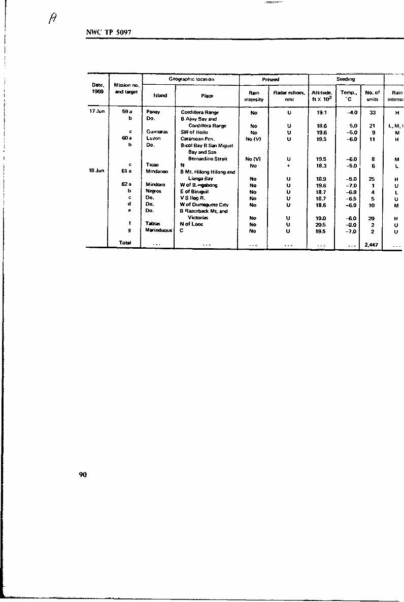
NWC TP 5097
Geographic location Preseed SeedingDate. Mission no.1969 and target Island Place Rain Radar echoes, Altitude, Temp., No. of Rain
intensity nmi ft X 103 uC units intensi
17 Jun 59a Panay Cordillera Range No U 19.1 -4.0 33b Do. BAjuy Bay and
Cordillera Rar'ge No U 18.6 5.0 21 L, M, ic Guamaras SW of Iloilo No U 19.6 -5.0 9 M
60 a Luzon Caramoan Pen. No (V) U 19.5 -6.0 11 Hb Do. 8 B00l Bay B San Miguel
Bay and San
Bernard;no Strait No (V) U 19.5 -6.0 8 Mc Ticao N No + 18.3 -5.0 6 L
18 Jun 61 a Mindanao B Mt. Hilong Hilong and
Lianga Say No U 18.9 -5.0 25 H62 a Mindoro W of B..gabong No U 19.6 -7.0 1 U
b Negros E of BinrJuil No U 18.7 -6.0 4 Lc Do. V S Iiog R. No U 18.7 -6.5 5 Ud Do. W of Dumaguete City No U 18.6 -6.0 10 Me Do. B Razctback Mt. and
Victorias No U 19.0 -6.0 20 Hf Tablas N of Looc No U 20.5 -43.0 2 Ug Marinduque C No U 19.5 -7.0 2 U
Total - - 2,447
90

TA I
15 (CntdI
echoes. Lineal dimensions Rain area. Ran Rain Estimated Commentsnmi of rain area. nims flin
2 duration, (ate, rainfall,hr mn/hr awe-ft X lop
U 60\ 20 120 -3 H 636
U 40X 35 1.400 -3 M 445 LWC 3.6 g1m 3 ; rain runU 3 X 5 15 -3 M 4.8 Extended clouds inland from N coastU U 60 3 H 31.8 Filled in gaps among natural storms
U U 50 -2.5 M 13.3 Filled in gaps among natural storms
3 ', 10 loX 15 150 (1) L 5.3 Partially over Masbate Strait
U U U U ... ..... IU U U U .......U 5 X 2 10 (0.2) L 0.1 Cloud dissipatedU U U U ... ... Slow prowth
6(D) 2X 10 20 MI) M ..1 .
U 15 (D) 175 (2) H 6; 8 Entire island covered with CU; Bacolod confirmed rainU U U U ... ...U U U U
I

NWC TP 5097
Appendix BOPERATIONAL CONSIDERATIONS
The seeding done by the (,RONI:T II team %sas clearly adequate to augmentrainfall from the type of cloudts found ovei the Philippines and indeed in manyplaces in the world. From these experiences it is well perhaps to suggest someguidelines for the use of rain enhancement technique% in areas outside the UnitedStates.
Forecasts
With rawinsonde and other data available, a capable forecaster can predictcloud locations adequately to be of use in deciding on the seeding plan for the
day's operations. Although helpful computer models exist, computer% are not usuallyavailable or are too expensive to consider for routine use:- nor are they necessary.
In general, a forecast will include the possibilht. o" orographic clouddevelopmient, even under conditions unfavorable to purely convectivc cumulusgrowth.
Once the forecast is in hand. aircraft should be launched, even under marginalconditions, to take advantage of any clouds that may be found. There are usuallysome that can be worked. Conditions change with time and place, and oftenweather stations do not report clouds, even though they may be seen from the airat a little distance. In drought conditions, air pollution often precludes good skyobservation.
Aircraft
. - Although the WC-130 military aircraft used during GRONIET I would be harU
to surpass in safety, comfort, and conenience. 'he work could !,j~e been done withmuch less expensive equipment,
At NWC we have used the --heapest single-engine light aircraft availab'e. Inmost areas of the world this is szoisfactory. but in some situations a multiengineaircraft is preferable.
Frequently. the local military can furnish crews ar.d aircraft capable ofreaching the seeding altitude, but fNel costs for suth aircratl ma% be prohibitive.Moreover, surplus reciprocating engine aircraft built in the 14-40s and l)50sgenerally cannot operate effectively at the altitudes required because ihey do nothave supercharged engines. Jets operate effectively at altitude but do not remainlong enough on st-.tion and fly so fast that targeting is difficult. Their fuel
consumption is also inordinately high."Any :.apercharged reciprocating or turbine-powered aircraft capable of Fustained
operation at 25.000 feet will do. A reasonably high cruise speed at altitude and ahigh rate of climb are important.
91

N%,(" iP 5097 1
lhe CesIia 210 Iti, a good ai•craft to- the purpose. Two external seeding racksfto dtoppable uim., ,ai he cairied., one under each wing. An excellent twin-engine.111iatt 1., the Ce,,it 337. This model can be operated on one engine at 18.000 feet
it) coniei,, uel xslide %aititlg lot development of clouds. Operating cost for the
Cesna 2110 is about S45 pet hour. and for the Cessna 337 the cost is about S60per hour. One such aiicraft can work an arej about 100 miles in radius very
ettectinely.('aictul consderation shotld be given to aircraft supplies and equipment'.
I. Supplemental oxygen should be cairied because the usual supplies are
inadequate. lPressuri/ed cabins are more confotitable but not necessary.
2. Dual navigation communication gear is necessary. A distance-measuring
apparatus is desirable. but in most places is not very useful because of lack ofground facihites. If possible the aircraft should have dual automatic direction finders
because most countries have many nondiiectional beacons. An instrument landing
sbsteni is desirable, In some areas high ;reiuency communication gear is advisable. Atransponder is generally tequied for t-igh altitude flights. but is not necessary unless
radar control is involved. Most air tr.fffic control radar cannot track a light plane
long without a transponder. especially if the plane is A Bellanca or Windecker
aircraft.
3. Aircraft radar is a convenience and of great use in estimating distance totargets and effects of seeding on targets, but is not required, It cannot be installed
easily in any single-engine aircraft and is usually not used in twin-engine plaives
because of cost.
4. Spare partt peculiar to the project aircraft should be brought along to the
base of operations b~cause. although most countries have good mechanics available.
spare parts are not oftes found in abundance,
Pilots
Local pilots who know and are interested in the country can serve very well.They should be instrument-rated o: at lea~t be .apable of short periods of
instrument flight in turbulence. If possible. after having listened to some lectures
and chalk talks on the subject, they should be trained to seed by another pilot
familiar with the technique.
Evaluation
Evaluation of the results may not be required, but it is a most importa-ft
factor and one of the most difficult to carry out, Because seeding projects are
generally conducted in dry areas where the need for maximum water production is
urgent, there is often little interest in a full-scale statistical experiment. Every
aircraft is needed to seed every cloud possible, Randomization to acquire scientific
information, so important to American experimenters, is generally not favored by
92
NWC AZP 5097
local officials nor indeed is any evaluation proceis that exceeds !0', of' tile projectI cost-Rainfall measurement is best done by well-calibrated radars, but these are
rarely found in sufficient number in most countries because of the :ost, Rain gauges-4 are perhaps the most practical means of measuring rain, but an enormous numberare needed. The observation and reporting are expensive even if the gauges are readonly once a day.
The real proof of effectiveness is in benefits to agriculture and irrigation, Inmany cases estimates of this sort can be made, but so many variables are at workthat one cannot always be sure the results isolated are it,leed the ones needed.
Local Participation
It is important to secure the active cooperation of local people in the-'I rainmaking operations. They should be included in the work to as large an extent aspossible and their advice and help should be sought. The irrigation. power. andwater management people are usually enthusiastic. The weather people are not as aStile vitally interested and ma] even offer some resistance, There must be acontinuous effort made to involve their in making the decisions that have to be
I made. Providing repsints from the seeding literv'ure, holding seminars, and taking afew local people along on seeding missions are some ways of gaining their interest inthe project, However, the people should be chosen with care. the activities limitedto good seeding days, and the air work confined at first tt. only mild penetrations
I because most people unaccustomed to such flights get airsick under conditions thatan experienced person would find dull.
!Hold Harmlem Agreement
I Before any seeding is done, a formal hold harmless agrcement. a legalagreement limiting liability on the part of the seeding party, should be entered intoby the participating governments and promulgated. Although there is little chance ofextensive damage, natural occurrences such as typhoons. hail. lightning strikes, andsimilar phenomena of an unexpected natwe. as well as complicated dis-benefitsbefalling certain, perhaps unsympathetic, groups could lead to interminable litigationand trouble.
The hold harmless clause together w:*h ,telligmnt restraint in the conduct ofthe operation and the wise use of local advice will preclude most such trouble.
Water Management
Often the lack of water points up a less than adequate vater managementsystem. It must be emphasized to the recipients that cloud seeding alone is notenough to solve problems perhaps centuries in the making and that a proper storageand distribution system is often the real need.
II 93

I
I-
I
Appendix C
PRELIMINARY CLOUD STUDIESIN THE PHILIPPINES-1%9
L
. 95

I
-p
PRELIMINARY CLOUD STUDIESIN THE PHILIPPINES-1%9
i.m
Report to
EARTH AND PLANETARY SCIENCES DIVISIONNAVAL WEAPONS CENTERCHINA LAKE. CALIFORNIA
Contract N66001-69-C-i 142
by
D. Ray Booker
Weather Science. Inc.
"Norman. Oklahoma
II
28 December 1970
97

NWC TP 5097
1.11 Purpowe
I na, a,,ked in April ol Ib004 to participate in the early phases of acloud-',eeding opeiation in the Philippines which became known as GROMET If. Mypurpose was
I. TO install two airborne meteorological instrumentation systems on two AirForce C-Il - , weather reconnaisance aircraft.
2. To iiake preliminary observations of clouds and their environments.3. To act as a scientafic" observer of seeding techniques and cloud reactions.4. To train military personnel in the use of equipment and making of
observations.I departed Norman. Oklahoma. on 27 April and returned on 29 May 1969.
2.0 Equipment.
The equipment used for installation on the Air Force weather reconnaissanceaircraft was removed from a Cessna 205 and a Piper Aztec where it had previouslybeen used in similar measurements within the Continental United States. The
equipment was reconditioned prior to shipment to the Philippines. The equipment.referred to as AMS-I I and AMS-15. was designed to measure various cloud andenvironmental parameters including rainrate. liquid water content, temperature,dewpoint and otheis. The ANIS-I5 was equipped with both analog and digitalrecording systems operating in parallel. The AMS-I I produced only analog records.The analog records were used for on-site preliminary analysis. The digital recordswere returned to the United States for processing and use in a motu detailedanalysts.
The AMS-15 was additionally furnished with a continuous ice nucleus counterof the NCAR-Bollay type. The ice nucleus counter produced printed digital recordsindependent of the analog and digital recordings previously mentioned.
For both aircraft, the instrumentation installations were made in the forwardright section of the cargo compartment. A shelf was improvised on the bulkhead tosupport the instruments and power supplies while providing a place for the operatorto work. Sensors were mounted on the aircraft skin on the right side of the aircraft.
Six military technicians were trained in the techniques of installing, operatingand maintaining the instrument systems. Nine weather observers and weather officerswere trained in the use of the equipment and analysis of the data for meteorologicalpurposes. Operation of the equipment was transferred systematically to militaryoperators during my stay in -he Philippines.
3.0 Preliminary Observations.
I participated in seeding flights on about half of the operational days while Iwas in the Phili' pines. I used the aircraft instrumentation systems ani visual
98A.

iNNWC TP 5097
observations in coming to the following preliminary conclusions:Even though the Philippine Islands were experiencing an unprecedented
drought, we were able to find clouds suitable for seeding on every day on which Iparticipated in flights. The clouds grew over the highest peaks in the mid. and lateafternoons. Bases varied from 3,0(X-10.000 ft. The clouds tended to organizethemselves along the mountain ranges. In general, they were extremely easy tooperate on because of their relative isolation and a natural tendency to organizethemselves in short lines. The liquid water content meters indicated rather wetconditions in most of the clouds. LWC values o( 4 gm/m 3 were common near thetops of the cumuli. The clouds were generally slightly sheared. Almost all
"" observations were made at or near the -7C level.Very few ram measurements were made since the aircraft were used primarily
for seeding. Therefore, no conclusive results regarding the character of the rain can"" be made from the rainrate measurements. However, the impression I have gained
from the ooservitions and data is that the rain was of high intensity, normallyreaching peak values above 100 mm/hr, Droplet concentrations were considerably
-- higher than those we experienced in seeding tests in New Mexico and Oklahoma.Ice nucleus measurements were made on most of the flights. We generally
found very few ice nuclei except in areas where we had been seeding. Most of the-. measurements were made at the -7C level. The environment, as might be expected.
was essentially clean at that level. The occasional ice nucleus checks at lower"altitudes indicated relatively few ice nuclei present.
-. I observed a great deal of smoke rising from cane fields on operational days.This smoke was frequently observed to enter the bases of cumuli growing nearby.The possibility that this air pollution was ineffective in modifying the clouds seemsremote to me. Although we had no quantitative way of measuring, my impressionwas that the clouds became very much of Continental character by addition of
-- condensation nuclei rather than the more efficient maritime type which normallyprevails at these latitudes
4.0 Impression of Seeding Effectiveness.
Seeding was conducted by Dr. St.-Amand and various members of the ChinaLake team, and military trainees. A large number of military personnel and"Philippine crew members were trained in the theory and practice of cold cloudseeding techniques.
The seeding material was placed carefully in the updraft. The number of' -- rounds was varied according to the strength and width of tle updraft encountered,
The clouds were carefully observed for growth. organization and glaciation.I was particularly impressed with the opportunity to enhance cloud
"organization. Since the clouds tended to occur in short lines, as determined bymountain ranges, the crews were able to watch the development carefully and toseed those turrets which would enhance this tendency by filling in or extending aline. My impression was that the seeding was effective in increasing cloud
Sorganization. Theoretically, this should greatly increase the available precipitation
1 99

NWC TP 5097
T
since increased cloud efficiency results from decreased entrainment and increasedinstability due to line orientation.
Subsequent related experiences in Project Hotshot, which has been conductedsince returning from the Philippines, used the same seeding material. The ice nucleiwere introduced from the base rather than the top because of aircraft limitations.The results indicated that rain at the cloud base was more than doubled as a resultof seeding. These results were statistically significant. We found that the raindropspectrum was significantly altered in a uniform manner as a result of seeding. Ourresulib would tend to indicate that similar results could be expected from the coldclouds seeded in the Philippines.
5.0 Recommendations.
All evidence from the flights ot ISROMET II and subsequent Hotshotexperiments would indicate significant positive results from seeding. This potentialshould have marked economic, military, and political significance. I wouldrecommend that a long-term agreement for further development of this technologyin cooperation with a friendly nation be devised. The results can and should be verybeneficial to both nations.
100
D

.1• I
IT
Appendix D
OBSERVATIONS AT GROMET 1i
I i0- i
~ .9
I i 101

OBSERVATIONS AT GROMET 11
by
Edwin X. Berry
Laboratory of Atmospheric PhysicsDesert Research Institute
University of NevadaRemo, Nevada
1i
[A.

NWC TF 5097
ABSTRACT
The systematic seeding of growing cumulus towers in a localized area withpyrotechnic drops at about the -5C level regularly gave rise to large thunderstonnswith heavy rain-showers, while unseeded cloud areas in the general vicinity producedlittle or no significant growth or rain. These are the qualitative conclusions of anindependent observer present at the GROMET 11 seeding operation in the PhilippineIslands during two weeks in June 1969.
104d.

LIWNWC TP 5097
!
•[ INJTRODUCTION
The followii~g is an account of the GROMET 11 cumulus seeding operation inthe Philippine Islands during the period June 1969. is w:.nesseJ by the author whowas invited to be rn independent observer. Since the purpose of the operation was tomake rain fall in designated drought areas as opposed to being experimental, therewere no means available other than the qualitative judgments of the observers tomeasure the outcome of this project, Exceptions are the rainfall and crop growthI- data gathered by the farmers, which apparently showed a rainfall increase over theprevious five years. This account will only be concerned with observations of theclouds and rain from aboard the C-130 seeding aircraft.
METEOROLOGICAL CONDITIONS
The observations took place during a two-week period near the end of the"transitional period during which the southwest monsoon was approaching Therewere a few days during this period when the island of Luzon at least wasobliterated with rain and the operation was cancelled. Ot'ernise during theoperation over the southern Ph.iippine islands there were scattered fair weathercumulus with bases around 3.000 ft., MSL and tops 16.000 to 18.000 ft. None ofthese produced any rain. They seemed to be only a moment"ry entity climbingrapidly to their peak then dissipating. Their lifetime seemed to be about 15 minutes:their diameters about half a kilometer, They were generally randomly scattered over"the land areas with some predomnance of occurrence near mountain ranges andupwind shores. Occasionally (i.e. about once per 104 km 2 per day) a large cumuluscloud would form and grow to about 30.000 ft.
SEEDING TECHNIQUE
A group of small cumulus clouds were selected which reached to at least the-2C level and preferably to the -5C level which were over an area that needed
water. The aircraft was flown into the tops of the more active towers, which usuallymeant flying about 19.000 ft. MSL (-SC. and approximately one pyrotechnic flareper 500 m was dropped in each actively growing cloud top itaversed. A few minuteslater the tops of more clouds which grew to at least - X were similarly seeded. Thistechnique was repeated for 15 to 30 minutes as more and more cumulus tops in thedesignated arca, usually no greater than 10 km X 10 kw.. began to grow near theseeded towers. The seeding proceeded by trying to fill in the gaps between thetowers where growing cloud developed between 0t-,'v.
I!1O

NWC TP 5097
The intention was to expand the total area of cloud and updraft in thepreferred region. If the whole cloud drifted with a wind only the towers on theupshear side were seeded in an attempt to make them grow together into one cloud.
As a largei cumulus cloud developed. perhaps now reaching 22,000 ft, and Ikm in diameter, the adjoining cumulus were seeded and frequently penetrations weremade of the towers while doing so. When the cloud was about 26,000 ft. and 2-3km in diameter the seeding was discontinued. Then either another area was soughtat least 80 km away o. the now growing storm was observed for about half anhour.
OBSERVED RESULTS
Generally. a few minutes after a tower was seeded it was observed during aturn. There was seldom any d&fficulty in distinguishing the seeded tower from theothers In virtually every case the seeded tower had grown approximately 2,000 ft.higher than nearby unseeded towers in 3 to 5 minutes after seeding and glaciationwas usually apparent at the top of the seeded tower.
As more towers in the vicinity were seeded, more towers seemed to grow bycomparison to other areas within sigut that were similar before the seeding began.Whether by the influence of the seeding or by a clever anticipation of nature, whentowers were seeded to fill in space between clouds these areas invarably filled m.Some 15 to 20 towers were seeded during the formation of each cumulo-nimbus.The observer witnessed some 8 cumulo-nimbus formations that developed subsequentto the seeding and only two cases when the seeding was not followed by athunderstorm, and these were cases where the clouds were very scarce. When thestorm was about 3 km in diameter, small cu growth was suppressed to at least 20km from the storm and the very small cu that did grow within 5 km of the stormswere noticeably tilted toward the storm. Most of these storms reached about 35,000ft., developed anvils, and persisted actively for about one hour during which timemoderate to heavy rain fell out the bottom. Four times the aircraft was flown downbelow the clcld and partially into the rain to verify that what was seen from abovewis indeed heavy rain. At times the visibility was less than one km in this rain.
Invariably the seeded storm was the most intense storm visible within about
100 km. About two hours after the seeding similar cu-nimbus sometimes developedabout 50 km from the seeded cell.
In one case a group of scattered small cumulus clouds on one end of an islandwere purposely selected for the seeding by this observer while at the opposite endof the island about 20 km away a larger cumulus group was forming that wouldhave been a better seeding target. The poorer target was chosen in order to see ifthe seeding technique could compete with nature when starting with a handicap.
The group chosen for seeding was marginal ind only two towers were highenough for seeding on tte first pass. It took ten miuites for another tower to comeup and an additional five minutes for another. Each o0 f'hese was given one flare. --
Although the group could still be classified as scattered cumulus, the convectionseemed to be intensifying. Thirty minutes after seeding began there were about threetowers topping at -T.000 ft. and perhaps six coming up !o 18,000 ft. and the cloud
106

! NWC TP 5097
INTRODUCTION
S-. The following is an account of the GROMET If cumulus seeding operation inthe Philippine Islands during the period June 1Q69. as witnessed by the author whowas invited to be an independent observer. Since the purpcse of the operation was to
make rain fall in designated drought areas as opposed to being experimental, therewere no means available other than the qualitative judgments of the observers tomeasure the outcome of this project. Exceptions are the rainfall and crop growthdata gathered by the farmers, which apparently showed a rainfall increase over the
previous five years. This account will only be concerned with observations of the4 clouds and rain from aboard the C-130 seeding aircraft.
METEOROLOGICAL CONDITIONS
t - The observations took place during a two-week period near the end of the
transitional period during which the southwest monsoon was approaching. Therewere a few days during this period when the island of Luzon at least was
obliterated with rain and the operation was cancelled& Otherwise during the
operation over the southern Philippine Islands there were scattered fair weathert "cumulus with bases around 3,000 ft, MSL and tops 16,000 to 18,000 ft. None of
-.7 these produced any rain. They seemed to be only a momentary entity climbingrapidly to their peak then dissipating. Their lifetime seenied to be about 15 minutes:their diameters about half a kilometer, They were generally randomly scattered over
-, the land areas with some predominance of occurrence near mountain ranges and
i upwind shores. Occasionally (i.e. about once per 104 km 2 per day) a large cumuluscloud would form and grow to about 30.000 ft.
SEEDING TECHNIQUE
A group of small cumulus clouds were selected which reached to at least the"-2C level and preferably to the -5C level which were over an area that needed
water. The aircraft was flown in.o :he tops of the more active towers. which usually"meant flying about 19.000 ft, MSL (-SC). and approximately one pyrotechnic flareper 500 m was dropped in each actively growing cloud top traversed. A few minutes
later the tops of more clouds which grew to at least -2C were similarly seeded. This"technique was repeated for 15 to 30 minutes as more and more cumulus tops in the
designated area, usually no greater titan 10 km X 10 kin. began to grow near the
seeded towers. The seeding proceeded by trying to fill in the gaps between the
towers where growing cloud developed between them.
Ii 105

NWC TP 5097 f
The intention was to expand the total area of cloud and updraft in thepreferred region. If the whole cloud drifted with a wind only the towers on theupshear side were seeded in an attempt to make them grow together into one cloud.
As a larger cumulus cloud developed, perhaps now reaching 22,000 ft. and Ikm in diameter, the adjoining cumulus were seeded and frequently penetrations weremade of the towers while doing so. When the cloud was about 26,000 ft, and 2-3km in diametet the seeding was discontinued. Then either another area was soughtat least 80 km away or the now growing storm was observed for about half anhour.
OBSERVED RESULTS
Generally. a few minutes after a tower was seeded it %as observed during aturn. There was seldom any difficulty in distinguishing the seeded tower from theothers. In virtually every case the seeded tower had grown approximately 2,000 ft,higher than nearby unseeied towers in 3 to 5 minutes after seeding and glaciationwas usually apparent at the top of the seeded tower.
As more towers in the vicinity were seeded, more towers seemed to grow bycomparison to other areas within sight that were similar before the seeding began.Whether by the influence of the seeding or by a clever anticipation of nature, whentowers were seeded to fill in space between clouds these areas invariably fdled in.Some 15 to 20 towvers were seeded during the formation of each cumulo-nimbus.The observer witnessed some 8 cumulo-nimbus formations that developed subsequentto the seeding and only two cases when the seeding was not followed by athunderstorm, acd these were cases where the clouds were very scarce. When thestorm was about 3 km in diameter, small cu growth was suppressed to at least 20km from the storm and the very small cu that did grow within 5 km of the stormswere noticeably tilted toward the storm. Most of these storms reached about 35,000ft.. developed anvils, and persisted actively for about one hour during which timemoderate to heavy rain fell out the bottom. Four times the aircraft was flown downbelow the cloud and partially into the rain to verify that what was seen from abovewas indeed heavy rain. At times the visibility was less than one km in this rain.
Invariably the seeded storm was the most intense sto M visible within about100 km. About two hours after the seeding similar cu-nimt us sometimes developedabout 50 km from the seeded cell.
In one case a group of scattered small cumulus clouds on one end of an islandwere purposely selected for the seeding by this observer while at the opposite endof the island about 20 km away a larger cumulus group was forming that wouldhave been a better seeding target. The poorer target was chosen in order to see ifthe seeding technique could compete with nature when starting with a handicap,
The group chosen for seeding was marginal and only two towers were highenough for seeding on the first pass. It took ten minutes for another tower to comeup and an additional five minutes for another, Each of these was given one flare.Although the group could still be classified as scattered cumulus, the convectionaseemed to be intensifying. Thirty minutes after seeding began there were about threetowers topiing at 20.000 ft. and perhaps six coming up to 18,000 ft. and the cloud
106

VNWC TP 5097
KT
cover in this group went from scattered to broken. Meanwlnle. at the other end ofthe island, nature was still ahead %ith a \tiong griup of clouds between 20.000 and
•, 2 ! '000 ft.One hour after seeding began the target area contained a large cumulus cloud
"about 5 km in diameter and gr.wing through 24.000 ft. The natural cloud seemedunchanged or even diminished during the previous half hour. Seeding was
discontinued.Ninety minutes after seeding began the target area coniatuied a cumulo-ninbus
cloud with heavy rainfall. The clouds at the opposite end of the island had ill butdissipated. and convection in that area seemed hindered by the ctmulo-um1bus inthe target area. The target area clouds ,e e the oniI ones to delher raiw to the
island that day.
IMPLICATIONS FOR THE FUTURE
Since the project was not an experiment, per w ,here uere no controls orstatistics, and the sequc.,,-e of events observed cannot be used to strongly imply a"cause-effect relationship between the seeding and the rain. However, the evident
possibility that such a relationship may have existed makes the seeding technique
worthy of description and worthy of future testing in a controlled experiment.
If the above described seeding technique does i:d.ed promote storms incertain circumstances, then the upward acceleration of an individual cumulus must
modify the local air flow in such a way that nearby growth is encouraged: ctherwisei -the result would be only higher single cells with the same area distribution as the
natural case. The relative importance of increased horizontal convergence and theeffect of vertical wind shear in causing mergers is not clearly known. If a way couldbe found to measure the airflow around the lower regions of cumulus clouds during
a secding experiment (or even in the natural case) much could be learned that might
suggest better seeding techniques.* Investigations into the formation of cloud merges and their artificial %,imulation
are indeed at the heart of the future problems in cloud modification.
r.
"CONCLUSIONS
It is the author's opinion that this was an ideal situation for such a seedingoperation. Although no precise measurements were availablel the repetitiie apparentsuccess of each attempt io produce rain seems to be some evid-nce in itself that theseeding indeed formed the large cumilo-nimbus clouds when natmue might not have
done so. The design of the seeding I :itrique to use latent heat release due to• ,4 freezing and careful placement of the flares to generate and organize a large strong
convective cell seems to make sense, It is the author's feeling that additional rainwas produced by having the warm rain process operate in an organized intensiveupdraft of longer duration than nature was producing and that the ice crystalsformed by seeding had a bearing on the precipitation only indirectly through their
intensification of the updraft.
1 1 107

NWC TP 5097
REFERENCES
I. Yap. Ldgardo F. Q.. Project Coordinator. Artificial Raiq Stinmulation in thePhilippines. L. Perfirinance Report on the 1969 Project. II. Proposed Work•
Program fior 1969-1970. Office of the Executive Secretary: Philippine SugarInstitute: National Federation of SUgar3Cne !L4.i•Ca•. Quezon City, ?fi~ ppimeIslands. 15 July i169.
2. St.-Amand. Pierre., Win. G. Finnegan. L. Lee Wilson, Sheldon D. Elliott. Jr.. andPaul T. Jorgensen. "Pyrotechnic Production of Nucleants for Cloud Modification:Part II. Pyrotechnic Compounds and Delivery Systems for Freezing Nucleants."The Journal of Weather Modification Vol., 2, No. I (May 1970), pp. 33-52.
3. Institute of Atmospheric Sciences. South Dakota School of Mines andTechnology. Final Report-Nucleation Efficienqy Tests Conducted for the NalWeapons Center Under Contract No. N60530-6-C-0006. by John A. Donnan andDonald N. Blair. Rapid City, S. Dak., South Dakota School of Mines andTechnology. July 1970. 20 pp. (Report 70.8.)
4. Warner. J. "A Reduction in Rainfall Associated with Smoke from Sugar-CaneFires--An Inadvertent Weather Modification?" APPL METEOROL, Vol. 7, No. 2(April 1968). pp. 247-51.
L!
1081