Инструкция По Двигателю d4dd
113
INSPECTION .......................................... EM -72 INSTALLATION ...................................... EM -73 INTAKE MAINIFOLD COMPONENTS ..................................... EM -75 REMOVAL .............................................. EM -76 INSPECTION .......................................... EM -76 INSTALLATION ...................................... EM -77 EXHAUST MANIFOLD COMPONENTS ..................................... EM -78 REMOVAL .............................................. EM -79 INSTALLATION ...................................... EM -80 AIR CLEANER COMPONENTS ..................................... EM -81 INSPECTION .......................................... EM -85 LUBRICATION SYSTEM DESCRIPTION ............................................. EM -86 SPECIFICATION ......................................... EM -90 TROUBLESHOOTING ................................ EM -92 ADJUSTMENT ............................................. EM -94 OIL PUMP COMPONENTS ..................................... EM -96 DISASSEMBLY ..................................... EM -98 OIL COOLER COMPONENTS ..................................... EM -99 DISASSEMBLY ..................................... EM -100 INSPECTION .......................................... EM -100 REASSEMBLY ...................................... EM -101 COOLING SYSTEM DESCRIPTION ............................................. EM -102 SPECIFICATION ......................................... EM -104 TROUBLESHOOTING ................................ EM - 106 WATER PUMP COMPONENTS ..................................... EM -108 REMOVAL .............................................. EM -109 INSPECTION .......................................... EM -110 INSTALLATION ...................................... EM -111 RADIATOR COMPONENTS ..................................... EM -112 REMOVAL .............................................. EM -113 INSPECTION .......................................... EM -113 INSTALLATION ...................................... EM -113 ENGINE MECHANI- CAL SYSTEM (D4DD) GENERAL DESCRIPTION ............................................. EM -2 SPECIFICATION ......................................... EM -6 SPECIAL TOOL ........................................... EM -12 DIAGNOSIS ................................................. EM -15 ADJUSTMENT ............................................. EM -16 TIMING SYSTEM TIMING GEAR ASSEMBLY COMPONENTS ..................................... EM -17 REMOVAL .............................................. EM -19 INSPECTION .......................................... EM -22 REPLACEMENT .................................... EM -25 INSTALLATION ...................................... EM -26 CYLINDER HEAD ASSEMBLY COMPONENTS ........................................... EM -31 REMOVAL ................................................... EM -33 DISASSEMBLY ........................................... EM -36 INSPECTION ............................................... EM -37 REPLACEMENT .......................................... EM -41 REASSEMBLY ............................................ EM -43 INSTALLATION ........................................... EM -44 CRANK CASE FLYWHEEL COMPONENTS ..................................... EM -46 REMOVAL .............................................. EM -47 INSPECTION .......................................... EM -47 INSTALLATION ...................................... EM -48 CYLINDER BLOCK ASSEMBLY COMPONENTS ..................................... EM -50 REMOVAL .............................................. EM -52 DISASSEMBLY ..................................... EM -55 INSPECTION .......................................... EM -55 REASSEMBLY ...................................... EM -61 INSTALLATION ...................................... EM -62 INTAKE AND EXHAUST SYSTEM SPECIFICATIONS ....................................... EM -66 TROUBLESHOOTING ................................ EM -67 TURBO CHARGER COMPONENTS ..................................... EM -69 REMOVAL .............................................. EM -71
-
Upload
bigfair-hd78 -
Category
Documents
-
view
145 -
download
0
description
Инструкция По Двигателю d4dd
Transcript of Инструкция По Двигателю d4dd
INSPECTION .......................................... EM -72INSTALLATION ...................................... EM -73
INTAKE MAINIFOLDCOMPONENTS ..................................... EM -75REMOVAL.............................................. EM -76INSPECTION .......................................... EM -76INSTALLATION ...................................... EM -77
EXHAUST MANIFOLDCOMPONENTS ..................................... EM -78REMOVAL.............................................. EM -79INSTALLATION ...................................... EM -80
AIR CLEANERCOMPONENTS ..................................... EM -81INSPECTION .......................................... EM -85
LUBRICATION SYSTEMDESCRIPTION ............................................. EM -86SPECIFICATION ......................................... EM -90TROUBLESHOOTING ................................ EM -92ADJUSTMENT ............................................. EM -94OIL PUMP
COMPONENTS ..................................... EM -96DISASSEMBLY ..................................... EM -98
OIL COOLERCOMPONENTS ..................................... EM -99DISASSEMBLY ..................................... EM -100INSPECTION .......................................... EM -100REASSEMBLY ...................................... EM -101
COOLING SYSTEMDESCRIPTION ............................................. EM -102SPECIFICATION ......................................... EM -104TROUBLESHOOTING ................................ EM - 106WATER PUMP
COMPONENTS ..................................... EM -108REMOVAL.............................................. EM -109INSPECTION .......................................... EM -110INSTALLATION ...................................... EM -111
RADIATORCOMPONENTS ..................................... EM -112REMOVAL.............................................. EM -113INSPECTION .......................................... EM -113INSTALLATION ...................................... EM -113
ENGINE MECHANI-CAL SYSTEM
(D4DD)GENERAL
DESCRIPTION............................................. EM -2SPECIFICATION ......................................... EM -6SPECIAL TOOL ........................................... EM -12DIAGNOSIS ................................................. EM -15ADJUSTMENT ............................................. EM -16
TIMING SYSTEMTIMING GEAR ASSEMBLY
COMPONENTS ..................................... EM -17REMOVAL.............................................. EM -19INSPECTION.......................................... EM -22REPLACEMENT .................................... EM -25INSTALLATION ...................................... EM -26
CYLINDER HEAD ASSEMBLYCOMPONENTS ........................................... EM -31REMOVAL ................................................... EM -33DISASSEMBLY........................................... EM -36INSPECTION ............................................... EM -37REPLACEMENT .......................................... EM -41REASSEMBLY ............................................ EM -43INSTALLATION ........................................... EM -44
CRANK CASEFLYWHEEL
COMPONENTS ..................................... EM -46REMOVAL.............................................. EM -47INSPECTION.......................................... EM -47INSTALLATION ...................................... EM -48
CYLINDER BLOCK ASSEMBLYCOMPONENTS ..................................... EM -50REMOVAL.............................................. EM -52DISASSEMBLY ..................................... EM -55INSPECTION.......................................... EM -55REASSEMBLY ...................................... EM -61INSTALLATION ...................................... EM -62
INTAKE AND EXHAUST SYSTEMSPECIFICATIONS....................................... EM -66TROUBLESHOOTING ................................ EM -67TURBO CHARGER
COMPONENTS ..................................... EM -69REMOVAL.............................................. EM -71

EM -2 ENGINE MECHANICAL SYSTEM
GENERAL
DESCRIPTION EFA0EBB7
COMBUSTION
CHAMBER
1. Combustion chamber consists of cylinder head, pis-ton, injector installed to the cylinder head and valve.
Valve guide
Cylinder head
Valve
Piston
Injector
SUDEM7001L
2. Fuel is supplied to supply pump through the fuel filterinstalled to the frame. Fuel is also supplied to injectorsthrough injection pipe No. 1, 2, 3 and 4 in common railassembly.
3. Combustion is accomplished when fuel is injected di-rectly into combustion chamber, at that time explosionpressure applies to the piston directly.
4. For better efficient cooling of combustion chamber,water director is press-fit under cylinder head floor,which induces the coolant flow.
Water director Engine coolant
SUDEM7002L
VALVE MECHANISM
1. Heat resistant steel with surface treatment is used forintake and exhaust valve. The valve seat angle is 45 .
2. Valve stem seal, installed to the stem, adjusts thelubricant amount on the sliding surface of valve andvalve guide.
NOTE
Valve guide with carbon cutter is used for exhaustvalve.
3. Valve spring consists of two valve springs having ir-regular pitches. The coil directions of inner and outersprings are opposite each other.
4. Rocker shaft is hollow cylindrical rod, whose each endare sealed with sealing cap. Inner space of the shaftis an engine oil passage.
5. Steel ball is installed to the lower end of push rod androcker assembly is installed to upper end.
6. Tappet has a cylindrical shape. As enlarging the con-tacting surface contacted with camshaft, it helps toprevent partial wear and to increase its durability.
Outer spring
Inner spring
Rocker
Rocker shaft
Push rod
Tappet Camshaft
Intake valveExhaust valve
Valve guide
Valve spring
SUDEM7003L

GENERAL EM -3
7. Camshaft assembly (1) consists of cam sensor plate,thrust plate, cam and journal. Camshaft gear is cou-pled with the idler gear A (2).
2
1
SUDEM7004L
CRANKCASE AND CYLINDER SLEEVE
1. Crankcase is manufactured firmly with cast iron toprevent stress concentration and deformation.
2. The 5 camshaft bushes are installed to the camshaftbore of the crankcase.To facilitate the removal and installation of camshaft,inner diameter of bush is tapered to the rear side.
Do not remove the cam sensor plate unless it is damaged.
SUDEM7005L
3. Cylinder sleeve made of special cast iron is pressedfit into the crankcase.
Cylinder sleeveCrank case
SUDEM7006L
PISTON
1. Piston pin type is full float type and piston pin is offsetfrom thrust.
2. Marks on the piston indicate weight, part number andoversize. The front mark indicates the front directionof the engine.
NOTE
When assembling a piston, let the arrow mark (→)faced to the center of cylinder head bolt hole.
Weight mark
Part numberFront mark
SUDEM7007L

EM -4 ENGINE MECHANICAL SYSTEM
PISTON RING
Piston has two compression rings and one oil ring. Allsliding surfaces of rings are coated with hardened chrome.
Compression ring No. 1
Compression ring No. 2
Oil ring No. 3
SUDEM7008L
CRANKSHAFT
1. Crankshaft is forged with high-strength alloy built inwith balance weight.
2. Pin, journal and oil seal sliding-surface are hardenedwith high frequency heat treatment to raise the resis-tance against frictional wear.
3. Through oil passage at the pin and journal, oil lubri-cates main bearing. Oil flows to the pin for the lubri-cation of connecting rod bearing.
4. Crankshaft pulley and crankshaft gear are installedat the front end of crankshaft. The crankshaft pulleydrives alternator and water pump using V-belt.
5. Crankshaft damper pulley absorbs the distorting vi-bration of crankshaft.
Journal
Crankshaft gear
Crankshaft damper pulley
Pin
Oil passage
SUDEM7009L
6. Crankshaft gear (1) drives camshaft gear (2), idlergear A (3), idler gear B (4), supply pump gear (5) andoil pump gear (6).
5
4
3
2
6 1
SUDEM7010L
CRANKSHAFT MAIN BEARING
Upper main bearing has oil groove and oil hole whichmatches with oil hole of the crankshaft.Divided type thrust plate is installed to the both ends of thelast bearing (No.5).
Upper main bearing (No. 5)
Upper main bearing (No. 1)
Lower main bearing
Thrust plate
SUDEM7011L
GENERAL EM -5
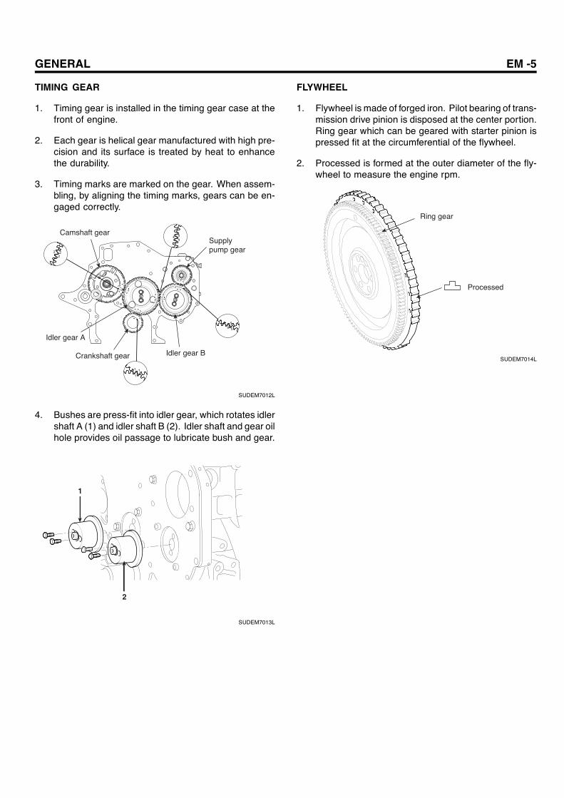
TIMING GEAR
1. Timing gear is installed in the timing gear case at thefront of engine.
2. Each gear is helical gear manufactured with high pre-cision and its surface is treated by heat to enhancethe durability.
3. Timing marks are marked on the gear. When assem-bling, by aligning the timing marks, gears can be en-gaged correctly.
Camshaft gearSupply pump gear
Idler gear A
Crankshaft gear Idler gear B
SUDEM7012L
4. Bushes are press-fit into idler gear, which rotates idlershaft A (1) and idler shaft B (2). Idler shaft and gear oilhole provides oil passage to lubricate bush and gear.
1
2
SUDEM7013L
FLYWHEEL
1. Flywheel is made of forged iron. Pilot bearing of trans-mission drive pinion is disposed at the center portion.Ring gear which can be geared with starter pinion ispressed fit at the circumferential of the flywheel.
2. Processed is formed at the outer diameter of the fly-wheel to measure the engine rpm.
Ring gear
Processed
SUDEM7014L

EM -6 ENGINE MECHANICAL SYSTEM
SPECIFICATION ECC41378
ItemsStandard
([ ] indicates standarddiameter)
Limit Correctiveaction
General Type
Cylinder inner diameterCylinder strokeDisplacementCompression ratioFiring orderMaximum output
Maximum torque
Compression pressure (at 200rpm)
Serial 4-cylinder 4strokecommon rail system
104mm115mm3,907cc17.5 : 11-3-4-2
140ps/2800rpm(HD65, 72,78 Narrow)
140ps/2800rpm(HD65, 72,78 Wide)
140ps/2800rpm (County)38kgf.m/1600rpm
(HD65, 72,78 Narrow)38kgf.m/1600rpm
(HD65, 72,78 Wide)38kgf.m/1600rpm (County)
26kg/cm² 20kg/cm²
Adjustment(As the
differencebetween
cylinders iswithin 4kg/cm² )
Valve timingIntake valve open (BTDC)Intake valve close (ABDC)Exhaust valve open(BBDC)Exhaust valve close (ATDC)
19536016
ValveIntake valve lengthExhaust valve lengthOuter diameter of intake valve stemOuter diameter of exhaust valve stemValve face angleThickness (margin) of intake/exhaust valve headValve clearance (when engine is cold)
137mm137mm
8.960~8.975mm8.925~8.940mm
451.5mm0.4mm
8.85mm8.85mm
1.2mm
Gap between valve stem and valve guideIntakeExhaust
[9] 0.04~0.06mm[9] 0.07~0.10mm
0.15mm0.2mm
Replace
Valve guide lengthIntakeExhaust
64mm71.5mm
Valve sinkageIntakeExhaust
0.75~1.25mm0.75~1.25mm
1.5mm1.5mm
Valve seatReplace insert
Push rod run out ― 0.4mm Replace
Valve seat widthIntakeExhaust
2.6~3.0mm1.8~2.2mm
3.6mm2.8mm
Replace
GENERAL EM -7
ItemsStandard
([ ] indicates standarddiameter)
Limit Correctiveaction
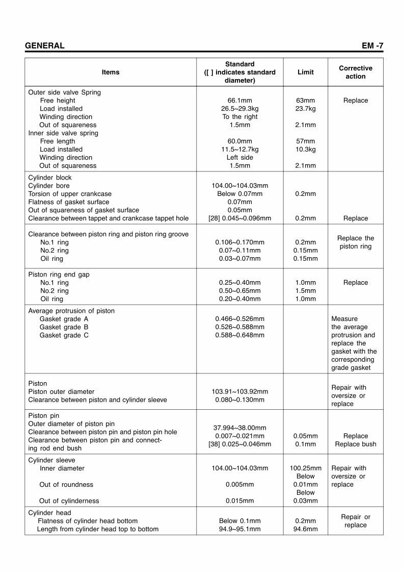
Outer side valve SpringFree heightLoad installedWinding directionOut of squareness
Inner side valve springFree lengthLoad installedWinding directionOut of squareness
66.1mm26.5~29.3kgTo the right
1.5mm
60.0mm11.5~12.7kg
Left side1.5mm
63mm23.7kg
2.1mm
57mm10.3kg
2.1mm
Replace
Cylinder blockCylinder boreTorsion of upper crankcaseFlatness of gasket surfaceOut of squareness of gasket surfaceClearance between tappet and crankcase tappet hole
104.00~104.03mmBelow 0.07mm
0.07mm0.05mm
[28] 0.045~0.096mm
0.2mm
0.2mm Replace
Clearance between piston ring and piston ring grooveNo.1 ringNo.2 ringOil ring
0.106~0.170mm0.07~0.11mm0.03~0.07mm
0.2mm0.15mm0.15mm
Replace thepiston ring
Piston ring end gapNo.1 ringNo.2 ringOil ring
0.25~0.40mm0.50~0.65mm0.20~0.40mm
1.0mm1.5mm1.0mm
Replace
Average protrusion of pistonGasket grade AGasket grade BGasket grade C
0.466~0.526mm0.526~0.588mm0.588~0.648mm
Measurethe averageprotrusion andreplace thegasket with thecorrespondinggrade gasket
PistonPiston outer diameterClearance between piston and cylinder sleeve
103.91~103.92mm0.080~0.130mm
Repair withoversize orreplace
Piston pinOuter diameter of piston pinClearance between piston pin and piston pin holeClearance between piston pin and connect-ing rod end bush
37.994~38.00mm0.007~0.021mm
[38] 0.025~0.046mm0.05mm0.1mm
ReplaceReplace bush
Cylinder sleeveInner diameter
Out of roundness
Out of cylinderness
104.00~104.03mm
0.005mm
0.015mm
100.25mmBelow
0.01mmBelow
0.03mm
Repair withoversize orreplace
Cylinder headFlatness of cylinder head bottomLength from cylinder head top to bottom
Below 0.1mm94.9~95.1mm
0.2mm94.6mm
Repair orreplace

EM -8 ENGINE MECHANICAL SYSTEM
ItemsStandard
([ ] indicates standarddiameter)
Limit Correctiveaction
Connecting rodConnecting rod twist and distortionOil clearance
Connecting rod bearingFree length of connecting rod bearing
Bearing crush (measured load 600kg)Connecting rod endplay
―0.04~0.099mm
―
34.53~34.57mm0.15~0.45mm
0.05mm0.2mm
Min.69.5mm―
0.6mm
Repair orreplace
CamshaftIntake cam max. lengthIntake cam min. lengthIntake cam liftExhaust cam max. lengthExhaust cam min. lengthExhaust cam liftCamshaft endplayClearance between camshaft journal and bushing
47.105mm39.910mm7.195mm
46.979mm39.658mm7.321mm
0.05~0.22mmStamp mark #1,2,3,4([54.5] 0.04~0.09mm)
Stamp mark #5([53] 0.04~0.09mm)
0.3mm
0.15mm Replace busing
CrankshaftOut of roundness of pin and journalOut of cylindricity of pin and journalCrankshaft distortion(measured at journal No.1 and No.5)Crankshaft endplay
Below 0.01mmBelow 0.006mmBelow 0.02mm
0.10~0.26mm
0.03mm0.03mm0.05mm
0.4mm Replace thrustplate
Crankshaft main bearingOil clearance (#1, 2, 4, 5)Oil clearance (#3)Free lengthBearing crush( measured load 500kgf)
0.036~0.098mm0.056~0.118mm
―41.061~41.101mm
0.15mm0.15mm
Min 69.5mm―
Replace
Timing gear backlashCrankshaft gear and idler gear AIdler gear A and cam shaft gearIdler gear A and idler gear BIdler gear B and supply pump gearCamshaft gear and power steering pump gearCrankshaft gear and oil pump gearPower steering pump gear and vacuum pump gear
0.062~0.159mm0.068~0.175mm0.062~0.160mm0.073~0.169mm0.075~0.160mm0.049~0.169mm0.075~0.160mm
Repair orreplace
Idler gear endplay 0.05~0.22mm 0.3mm Replace thrustplate
Clearance between idler busing and idler shaft [45] 0.025~0.06mm 0.1mm Replace busing
FlywheelDistortion of frictional surfaceHeight of frictional surfaceRun-out of frictional surface (while installed)
Below 0.05mm24.5mm
Below 0.1mm
0.2mm23.5mm0.2mm
Repair orreplace

GENERAL EM -9
TIGHTENING TORQUE
Items (diameter × length)Screw sizeO.D×pitch
(mm)Nm kgf.m Ib-ft
Main bearing cap bolt M14×2.0 49+90 5.0+90 36.4+90
Front plate flange bolt(8 ×16) ― 18.6~27.4 1.9~2.8 13.8~20.4
Rear oil seal slinger flange bolt(6×12) ― 7.8~11.8 0.8~1.2 5.8~8.7
Supply pump side timing gear casemounting bolt ― 18.6~27.4 1.9~2.8 13.8~20.4
Supply pump flange bolt ― 16.7~25.5 1.7~2.6 12.4~18.9
Oil jet check valve M12×1.25 29.4 3.0 21.8
Rear plate flange bolt(10×22) M10×1.5 63.7 6.5 47.3
Rear stiffener bracket flange bolt(8 ×55) ― 18.6~27.4 1.9~2.8 13.8~20.4
Rear stiffener bracket flange bolt (10×90) ― 38.2~58.8 3.9~6.0 28.4~43.6
Engine mounting bracket mounting bolt ― 32.3~49 3.3~5.0 24~36.4
Cylinderblock
Crankcase oil line set screw M10×1.5 24.5 2.5 18.2
Oil strainer flange bolt(8 ×16) ― 18.6~27.4 1.9~2.8 13.8~20.4
Oil strainer flange bolt (8 ×40) ― 18.6~27.4 1.9~2.8 13.8~20.4
Oil pan mounting flange bolt (8×12) M8×1.2 18.6~27.4 1.9~2.8 13.8~20.4
Oil level gauge mounting flange bolt(8×16) ― 18.6~27.4 1.9~2.8 13.8~20.4
Oil pan drain plug M14×1.5 34.3~39.2 3.5~4.0 25.4~29.1
Oil filter element M26×1.5 19.6 2.0 14.5
Oil cooler by-pass M16×1.5 19.6 2.0 14.5
Oil cooler relief valve M16×1.5 19.6 2.0 14.5
Oil cooler drain plug M14×1.5 34.3 3.5 25.4
Oil cooler mounting flange bolt ― 18.6~27.4 1.9~2.8 13.8~20.4
Oil line flange bolt ― 7.8~11.8 0.8~1.2 5.8~8.7
Oil line eyebolt ― 18.6~22.5 1.9~2.3 13.8~16.7
Idler gear oil supply pipe ― 18.6~22.5 1.9~2.3 13.8~16.7
Turbo charger oil pipe eyebolt ― 18.6~22.5 1.9~2.3 13.8~16.7
Lubricationsystem
Turbo charger oil pipe flange bolt(8×16) ― 18.6~27.4 1.9~2.8 13.8~20.4
Oil pump Oil pump mounting flange bolt(8 ×55) ― 18.6~27.4 1.9~2.8 13.8~20.4
Cylinder head mounting bolt M14×2.0 147+90 15.0+90 109+90
Cylinder head stud (10×25) ― 34.3 3.5 25.4
Cylinderhead
Cylinder head stud (10×48) ― 34.3 3.5 25.4
EM -10 ENGINE MECHANICAL SYSTEM
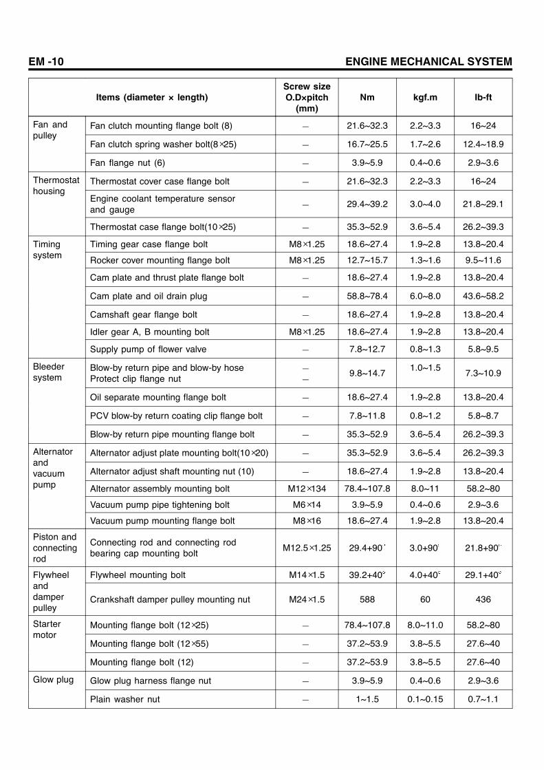
Items (diameter × length)Screw sizeO.D×pitch
(mm)Nm kgf.m Ib-ft
Fan clutch mounting flange bolt (8) ― 21.6~32.3 2.2~3.3 16~24
Fan clutch spring washer bolt(8×25) ― 16.7~25.5 1.7~2.6 12.4~18.9
Fan andpulley
Fan flange nut (6) ― 3.9~5.9 0.4~0.6 2.9~3.6
Thermostat cover case flange bolt ― 21.6~32.3 2.2~3.3 16~24
Engine coolant temperature sensorand gauge ― 29.4~39.2 3.0~4.0 21.8~29.1
Thermostathousing
Thermostat case flange bolt(10×25) ― 35.3~52.9 3.6~5.4 26.2~39.3
Timing gear case flange bolt M8×1.25 18.6~27.4 1.9~2.8 13.8~20.4
Rocker cover mounting flange bolt M8×1.25 12.7~15.7 1.3~1.6 9.5~11.6
Cam plate and thrust plate flange bolt ― 18.6~27.4 1.9~2.8 13.8~20.4
Cam plate and oil drain plug ― 58.8~78.4 6.0~8.0 43.6~58.2
Camshaft gear flange bolt ― 18.6~27.4 1.9~2.8 13.8~20.4
Idler gear A, B mounting bolt M8×1.25 18.6~27.4 1.9~2.8 13.8~20.4
Timingsystem
Supply pump of flower valve ― 7.8~12.7 0.8~1.3 5.8~9.5
Blow-by return pipe and blow-by hoseProtect clip flange nut
――
9.8~14.71.0~1.5
7.3~10.9
Oil separate mounting flange bolt ― 18.6~27.4 1.9~2.8 13.8~20.4
PCV blow-by return coating clip flange bolt ― 7.8~11.8 0.8~1.2 5.8~8.7
Bleedersystem
Blow-by return pipe mounting flange bolt ― 35.3~52.9 3.6~5.4 26.2~39.3
Alternator adjust plate mounting bolt(10×20) ― 35.3~52.9 3.6~5.4 26.2~39.3
Alternator adjust shaft mounting nut (10) ― 18.6~27.4 1.9~2.8 13.8~20.4
Alternator assembly mounting bolt M12×134 78.4~107.8 8.0~11 58.2~80
Vacuum pump pipe tightening bolt M6×14 3.9~5.9 0.4~0.6 2.9~3.6
Alternatorandvacuumpump
Vacuum pump mounting flange bolt M8×16 18.6~27.4 1.9~2.8 13.8~20.4
Piston andconnectingrod
Connecting rod and connecting rodbearing cap mounting bolt
M12.5×1.25 29.4+90 3.0+90 21.8+90
Flywheel mounting bolt M14×1.5 39.2+40 4.0+40 29.1+40Flywheelanddamperpulley
Crankshaft damper pulley mounting nut M24×1.5 588 60 436
Mounting flange bolt (12×25) ― 78.4~107.8 8.0~11.0 58.2~80
Mounting flange bolt (12×55) ― 37.2~53.9 3.8~5.5 27.6~40
Startermotor
Mounting flange bolt (12) ― 37.2~53.9 3.8~5.5 27.6~40
Glow plug harness flange nut ― 3.9~5.9 0.4~0.6 2.9~3.6Glow plug
Plain washer nut ― 1~1.5 0.1~0.15 0.7~1.1

GENERAL EM -11
Items (diameter × length)Screw sizeO.D×pitch
(mm)Nm kgf.m Ib-ft
Actuator mounting flange bolt ― 7.8~11.8 0.8~1.2 5.8~8.7
Butterfly valve shaft mounting nut (8) ― 16.7~27.4 1.7~2.8 12.4~20.4
Intake manifold front hanger mountingflange bolt (10×20) ― 32.3~49 3.3~5.0 24~36.4
Intakemanifold
Intake manifold mounting flange bolt (8 ×20) ― 18.6~27.4 1.9~2.8 13.8~20.4
Exhaust manifold heater protectorcover mounting bolt
M8×1.25 11.8 1.2 8.7Exhaustmanifold
Exhaust manifold assembly self lockFlange nut M10×1.25 41.2 4.2 30.5
Enginecover
Top shield bolt screw ― 7.8~11.8 0.8~1.2 5.8~8.7
Turbo charger and intake pipe clamp band M9×2.5 3.9 0.4 2.9Turbocharger Turbo charger oil pipe eyebolt M8×1.25 11.8 1.2 8.7
Fuel suction hose ― 14.7~19.6 1.5~2.0 10.9~14.5
Common rail fuel return B mounting screw ― 16.7~22.5 1.7~2.3 12.4~16.7
Fuel return A and fuel supply hoseprotect clip flange bolt ― 9.8~19.6 1.0~2.0 7.3~14.5
Fuel return A and rear plate clamp plate bolt ― 3.9~5.9 0.4~0.6 2.9~3.6
Injector pipe (No.1, 2, 3, 4) ― 39.2~49 4.0~5.0 29.1~36.4
Injector nozzle bridge bolt ― 30.4~34.3 3.1~3.5 22.5~25.4
Common rail bracket Flange bolt ― 21.6~32.3 2.2~3.3 16~24
Fuelsystem
Pipe (between supply pump and common rail) ― 39.2~49 4.0~5.0 29.1~36.4
Engine speed sensor mounting bolt ― 7.8~11.8 0.8~1.2 5.8~8.7
Cam speed sensor mounting bolt ― 7.8~11.8 0.8~1.2 5.8~8.7
Sensor
Booster pressure sensor (M.A.P)mounting bolt ― 7.8~11.8 0.8~1.2 5.8~8.7

EM -12 ENGINE MECHANICAL SYSTEM
SPECIAL TOOL E2E65F7D
Tool (part no. and part name) Shape Usage
09212-41200Camshaft bushing removerand installer
KDDEM5015A
Installation and removal ofcamshaft bushing
09246-41000Idler gear bushing puller
KDDEM5016A
Installation and removal of connectingrod bushing
09222-83200Piston guide clamp
KDDEM5017A
Installation of piston
09222-83300Valve spring compressor
KDDEM5018A
Installation and removal of valve cotter
09221-41100Valve guide remover
KDDEM5019A
Removal of valve guide

GENERAL EM -13
Tool (part no. and part name) Shape Usage
09221-41150Valve guide installer
KDDEM5020A
Installation of valve guide(Use together with 09211-41100)
09222-45100Valve stem seal installer
KDDEM5021A
Installation of valve stem seal
09353-45100Air compressor adapter
KDDEM5022A
Measurement of compressionpressure
09222-83200Piston ring tool
KDDEM5023A
Installation and removal of piston ring

EM -14 ENGINE MECHANICAL SYSTEM
Tool (part no. and part name) Shape Usage
09222-45000Rocker bush puller
KDDEM5024A
Installation and removal of rocker bush
09211-41000Oil seal slinger installer
KDDEM5025A
Installation and removal of crankshaftrear oil seal slinger
GENERAL EM -15
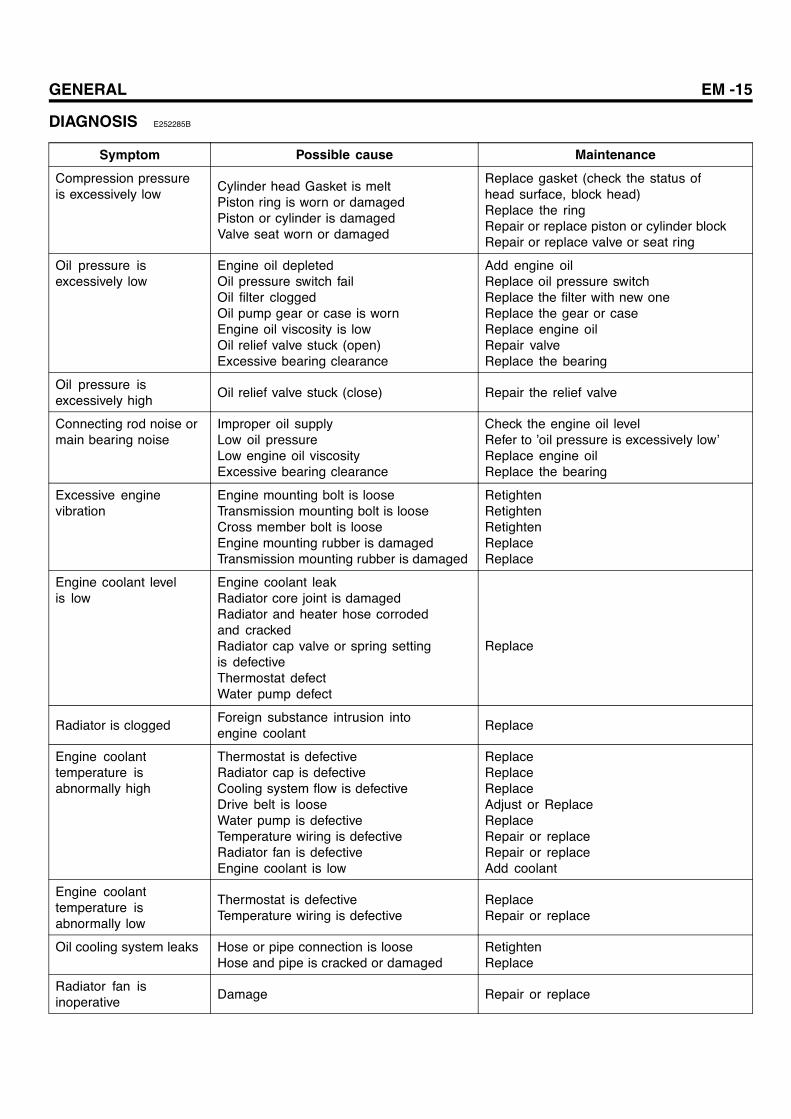
DIAGNOSIS E252285B
Symptom Possible cause Maintenance
Compression pressureis excessively low
Cylinder head Gasket is meltPiston ring is worn or damagedPiston or cylinder is damagedValve seat worn or damaged
Replace gasket (check the status ofhead surface, block head)Replace the ringRepair or replace piston or cylinder blockRepair or replace valve or seat ring
Oil pressure isexcessively low
Engine oil depletedOil pressure switch failOil filter cloggedOil pump gear or case is wornEngine oil viscosity is lowOil relief valve stuck (open)Excessive bearing clearance
Add engine oilReplace oil pressure switchReplace the filter with new oneReplace the gear or caseReplace engine oilRepair valveReplace the bearing
Oil pressure isexcessively high
Oil relief valve stuck (close) Repair the relief valve
Connecting rod noise ormain bearing noise
Improper oil supplyLow oil pressureLow engine oil viscosityExcessive bearing clearance
Check the engine oil levelRefer to ’oil pressure is excessively low’Replace engine oilReplace the bearing
Excessive enginevibration
Engine mounting bolt is looseTransmission mounting bolt is looseCross member bolt is looseEngine mounting rubber is damagedTransmission mounting rubber is damaged
RetightenRetightenRetightenReplaceReplace
Engine coolant levelis low
Engine coolant leakRadiator core joint is damagedRadiator and heater hose corrodedand crackedRadiator cap valve or spring settingis defectiveThermostat defectWater pump defect
Replace
Radiator is cloggedForeign substance intrusion intoengine coolant
Replace
Engine coolanttemperature isabnormally high
Thermostat is defectiveRadiator cap is defectiveCooling system flow is defectiveDrive belt is looseWater pump is defectiveTemperature wiring is defectiveRadiator fan is defectiveEngine coolant is low
ReplaceReplaceReplaceAdjust or ReplaceReplaceRepair or replaceRepair or replaceAdd coolant
Engine coolanttemperature isabnormally low
Thermostat is defectiveTemperature wiring is defective
ReplaceRepair or replace
Oil cooling system leaks Hose or pipe connection is looseHose and pipe is cracked or damaged
RetightenReplace
Radiator fan isinoperative
Damage Repair or replace
EM -16 ENGINE MECHANICAL SYSTEM
Symptom Possible cause Maintenance
Exhaust gas leaks Connection is loosePipe or muffler is damaged
RetightenRepair or replace
Unusual noise Baffle plate inside the muffler fell offRubber hanger is damagedPipe or muffler interferes with the bodyPipe or muffler is damaged
ReplaceReplaceRepairRepair or replace
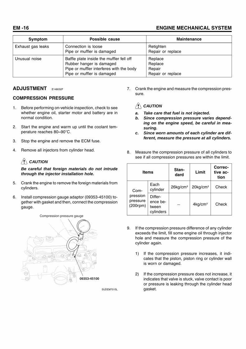
ADJUSTMENT E148032F
COMPRESSION PRESSURE
1. Before performing on-vehicle inspection, check to seewhether engine oil, starter motor and battery are innormal condition.
2. Start the engine and warm up until the coolant tem-perature reaches 80~90 C.
3. Stop the engine and remove the ECM fuse.
4. Remove all injectors from cylinder head.
CAUTIONBe careful that foreign materials do not intrudethrough the injector installation hole.
5. Crank the engine to remove the foreign materials fromcylinders.
6. Install compression gauge adaptor (09353-45100) to-gether with gasket and then, connect the compressiongauge.
09353-45100
Compression pressure gauge
SUDEM7015L
7. Crank the engine and measure the compression pres-sure.
CAUTION
a. Take care that fuel is not injected.b. Since compression pressure varies depend-
ing on the engine speed, be careful in mea-suring.
c. Since worn amounts of each cylinder are dif-ferent, measure the pressure at all cylinders.
8. Measure the compression pressure of all cylinders tosee if all compression pressures are within the limit.
Items Stan-dard Limit
Correc-tive ac-
tion
Eachcylinder
26kg/cm² 20kg/cm² CheckCom-
pressionpressure(200rpm)
Differ-ence be-tweencylinders
― 4kg/cm² Check
9. If the compression pressure difference of any cylinderexceeds the limit, fill some engine oil through injectorhole and measure the compression pressure of thecylinder again.
1) If the compression pressure increases, it indi-cates that the piston, piston ring or cylinder wallis worn or damaged.
2) If the compression pressure does not increase, itindicates that valve is stuck, valve contact is pooror pressure is leaking through the cylinder headgasket.
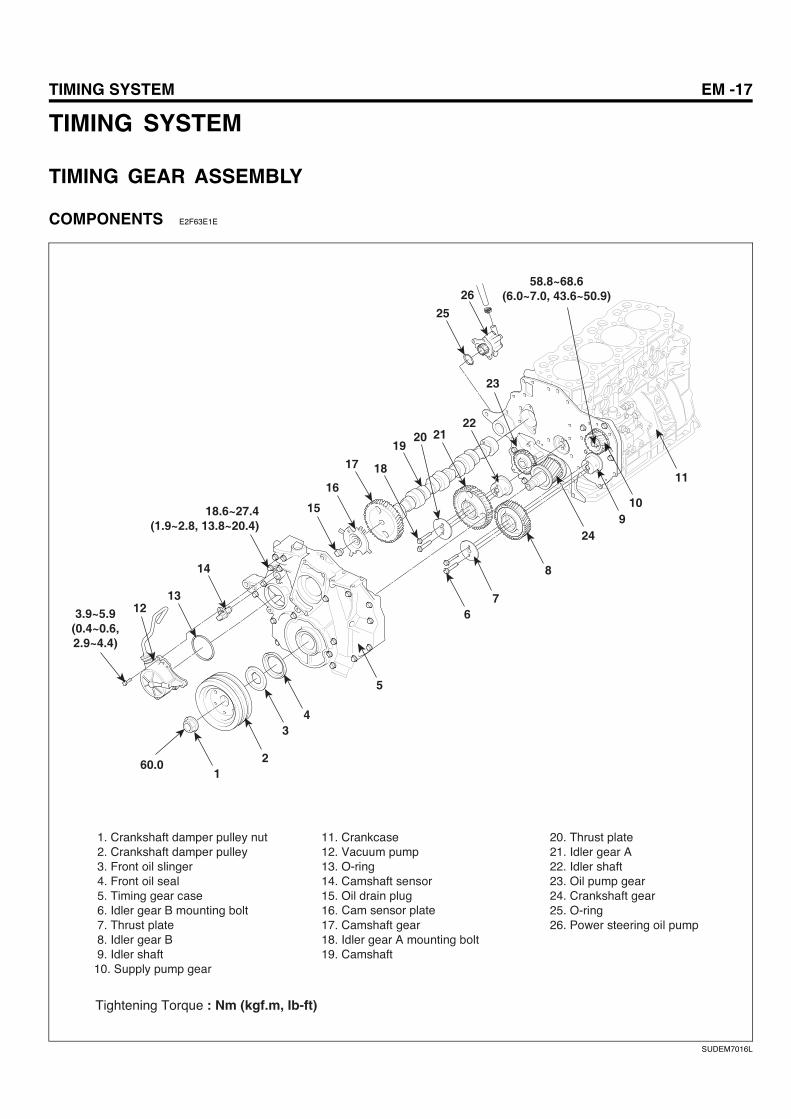
TIMING SYSTEM EM -17
TIMING SYSTEM
TIMING GEAR ASSEMBLY
COMPONENTS E2F63E1E
20. Thrust plate21. Idler gear A22. Idler shaft23. Oil pump gear24. Crankshaft gear25. O-ring26. Power steering oil pump
12
34
5
67
8
910
11
1213
14
18.6~27.4(1.9~2.8, 13.8~20.4)
3.9~5.9(0.4~0.6,2.9~4.4)
60.0
15
16
17 18
1920 21
22
23
24
25
2658.8~68.6
(6.0~7.0, 43.6~50.9)
Tightening Torque : Nm (kgf.m, Ib-ft)
Cam sensor plate
SUDEM7016L
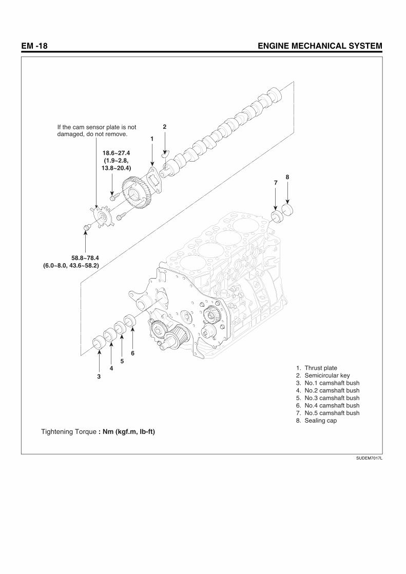
EM -18 ENGINE MECHANICAL SYSTEM
1
2
34
56
78
58.8~78.4(6.0~8.0, 43.6~58.2)
18.6~27.4(1.9~2.8,
13.8~20.4)
1. Thrust plate2. Semicircular key 3. No.1 camshaft bush4. No.2 camshaft bush5. No.3 camshaft bush6. No.4 camshaft bush7. No.5 camshaft bush8. Sealing cap
If the cam sensor plate is not damaged, do not remove.
Tightening Torque : Nm (kgf.m, Ib-ft)
SUDEM7017L
TIMING SYSTEM EM -19
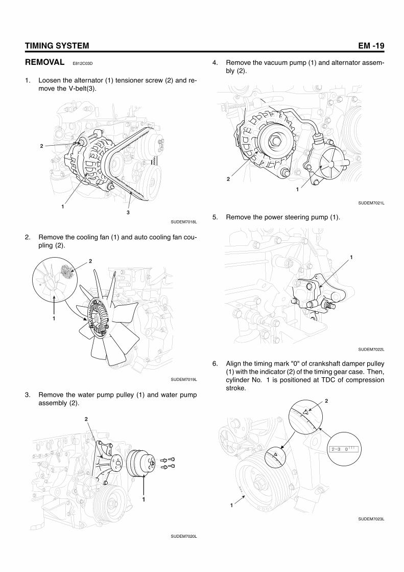
REMOVAL E812C03D
1. Loosen the alternator (1) tensioner screw (2) and re-move the V-belt(3).
13
2
SUDEM7018L
2. Remove the cooling fan (1) and auto cooling fan cou-pling (2).
1
2
SUDEM7019L
3. Remove the water pump pulley (1) and water pumpassembly (2).
2
1
SUDEM7020L
4. Remove the vacuum pump (1) and alternator assem-bly (2).
1
2
SUDEM7021L
5. Remove the power steering pump (1).
1
SUDEM7022L
6. Align the timing mark "0" of crankshaft damper pulley(1) with the indicator (2) of the timing gear case. Then,cylinder No. 1 is positioned at TDC of compressionstroke.
1
2
SUDEM7023L
EM -20 ENGINE MECHANICAL SYSTEM
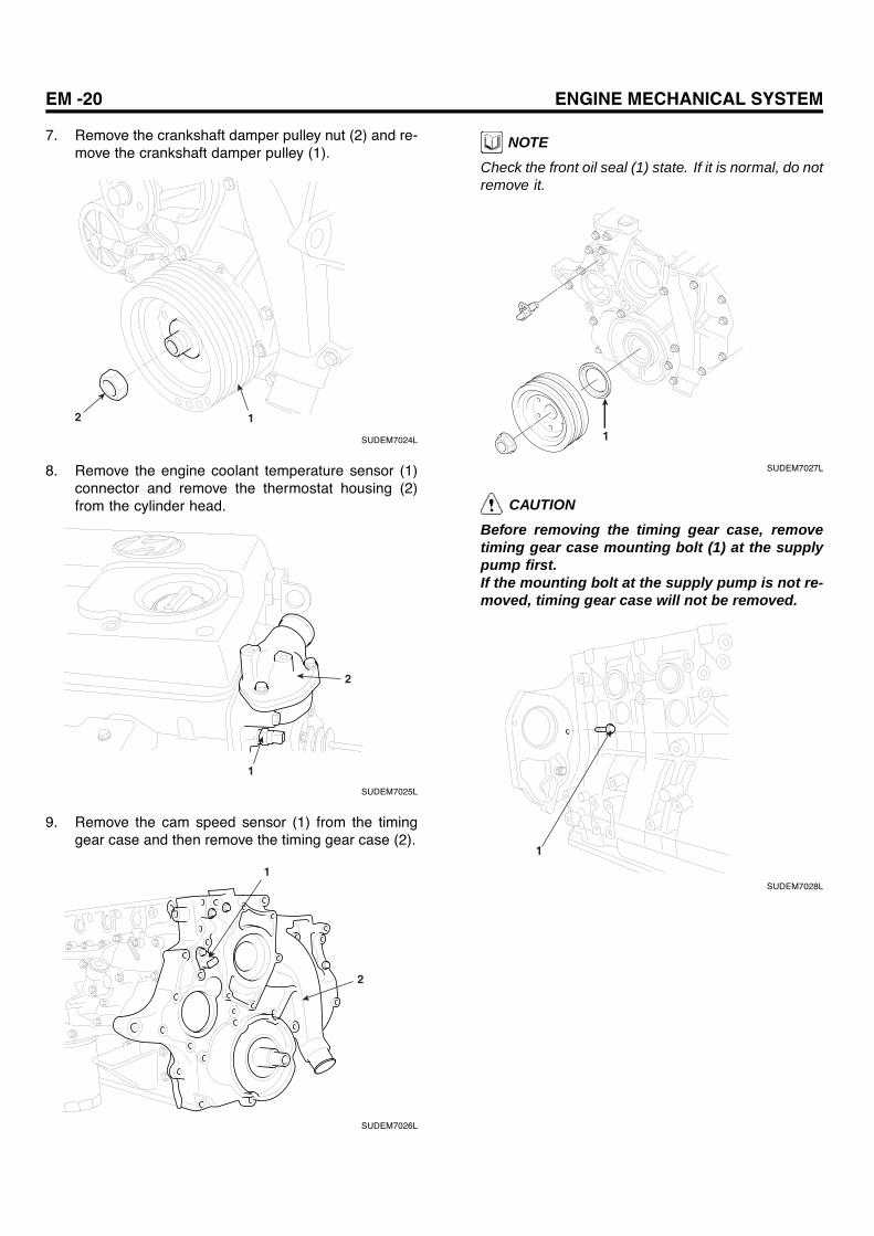
7. Remove the crankshaft damper pulley nut (2) and re-move the crankshaft damper pulley (1).
2 1
SUDEM7024L
8. Remove the engine coolant temperature sensor (1)connector and remove the thermostat housing (2)from the cylinder head.
2
1
SUDEM7025L
9. Remove the cam speed sensor (1) from the timinggear case and then remove the timing gear case (2).
1
2
SUDEM7026L
NOTECheck the front oil seal (1) state. If it is normal, do notremove it.
1
SUDEM7027L
CAUTIONBefore removing the timing gear case, removetiming gear case mounting bolt (1) at the supplypump first.If the mounting bolt at the supply pump is not re-moved, timing gear case will not be removed.
1
SUDEM7028L

TIMING SYSTEM EM -21
10. Remove the front oil seal slinger (1).
1
SUDEM7029L
11. Remove the oil pump gear (1).
1
SUDEM7030L
12. Remove the idler gear A (1).
1
SUDEM7031L
13. Remove the idler gear B (1).
1
SUDEM7032L
14. Remove the supply pump gear (1).
1
SUDEM7033L
15. Remove the camshaft assembly.1. Remove the thrust plate-mounting bolt (4)
through cam sensor plate (2) hole (3) of camshaftgear (1).
1
4
23
SUDEM7034L
EM -22 ENGINE MECHANICAL SYSTEM
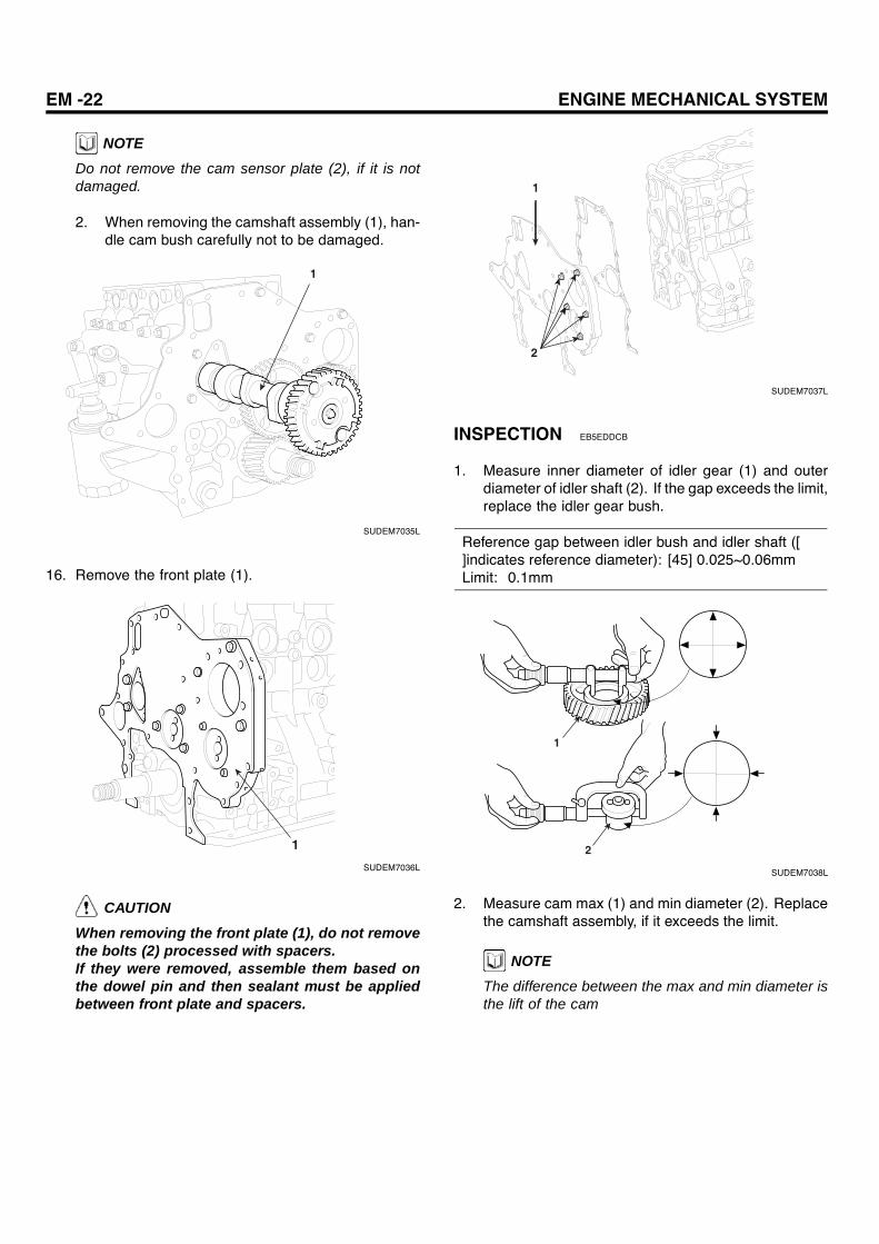
NOTEDo not remove the cam sensor plate (2), if it is notdamaged.
2. When removing the camshaft assembly (1), han-dle cam bush carefully not to be damaged.
1
SUDEM7035L
16. Remove the front plate (1).
1
SUDEM7036L
CAUTION
When removing the front plate (1), do not removethe bolts (2) processed with spacers.If they were removed, assemble them based onthe dowel pin and then sealant must be appliedbetween front plate and spacers.
1
2
SUDEM7037L
INSPECTION EB5EDDCB
1. Measure inner diameter of idler gear (1) and outerdiameter of idler shaft (2). If the gap exceeds the limit,replace the idler gear bush.
Reference gap between idler bush and idler shaft ([]indicates reference diameter): [45] 0.025~0.06mmLimit: 0.1mm
1
2
SUDEM7038L
2. Measure cam max (1) and min diameter (2). Replacethe camshaft assembly, if it exceeds the limit.
NOTE
The difference between the max and min diameter isthe lift of the cam
TIMING SYSTEM EM -23
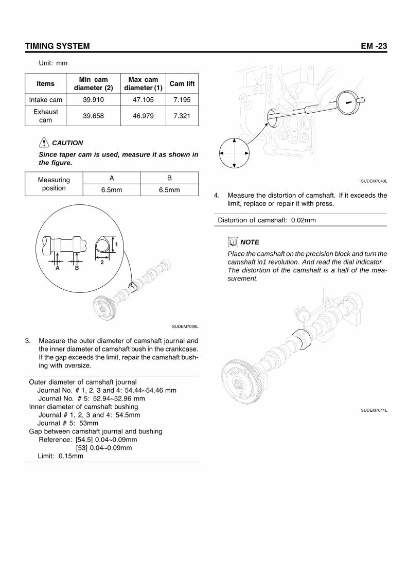
Unit: mm
Items Min camdiameter (2)
Max camdiameter (1) Cam lift
Intake cam 39.910 47.105 7.195
Exhaustcam
39.658 46.979 7.321
CAUTION
Since taper cam is used, measure it as shown inthe figure.
A BMeasuringposition 6.5mm 6.5mm
A B2
1
SUDEM7039L
3. Measure the outer diameter of camshaft journal andthe inner diameter of camshaft bush in the crankcase.If the gap exceeds the limit, repair the camshaft bush-ing with oversize.
Outer diameter of camshaft journalJournal No. # 1, 2, 3 and 4: 54.44~54.46 mmJournal No. # 5: 52.94~52.96 mm
Inner diameter of camshaft bushingJournal # 1, 2, 3 and 4: 54.5mmJournal # 5: 53mm
Gap between camshaft journal and bushingReference: [54.5] 0.04~0.09mm
[53] 0.04~0.09mmLimit: 0.15mm
SUDEM7040L
4. Measure the distortion of camshaft. If it exceeds thelimit, replace or repair it with press.
Distortion of camshaft: 0.02mm
NOTE
Place the camshaft on the precision block and turn thecamshaft in1 revolution. And read the dial indicator.The distortion of the camshaft is a half of the mea-surement.
SUDEM7041L
EM -24 ENGINE MECHANICAL SYSTEM
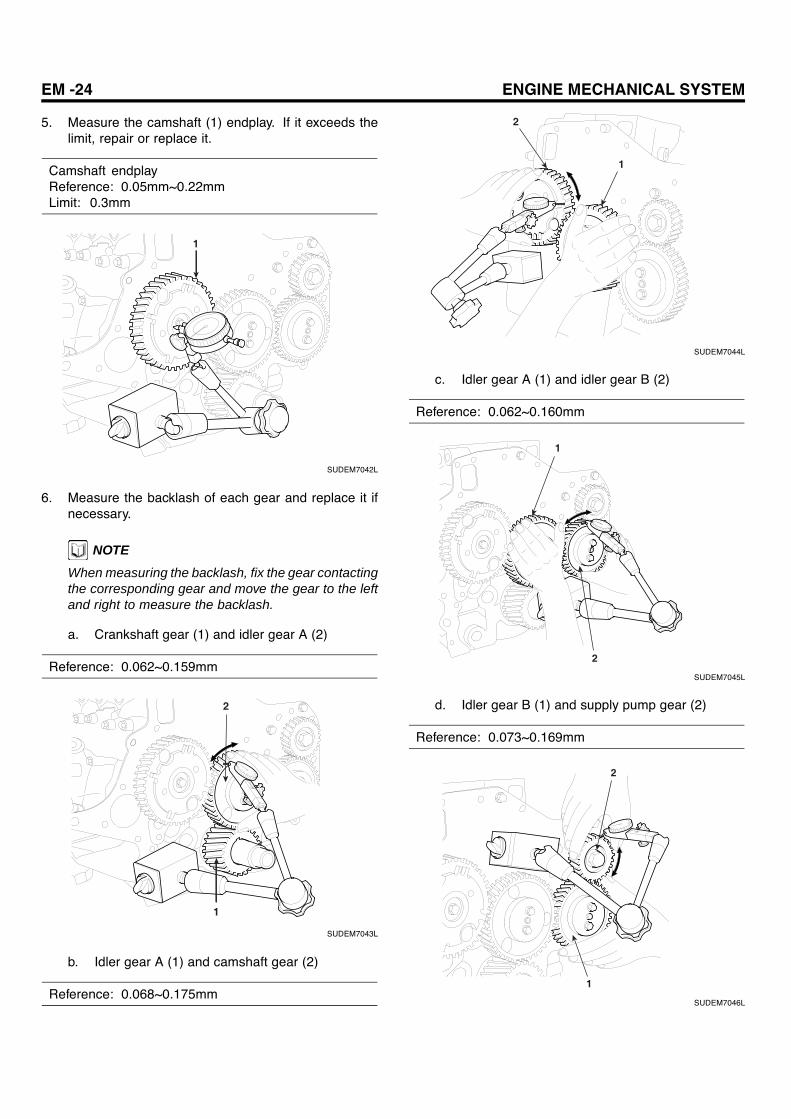
5. Measure the camshaft (1) endplay. If it exceeds thelimit, repair or replace it.
Camshaft endplayReference: 0.05mm~0.22mmLimit: 0.3mm
1
SUDEM7042L
6. Measure the backlash of each gear and replace it ifnecessary.
NOTEWhen measuring the backlash, fix the gear contactingthe corresponding gear and move the gear to the leftand right to measure the backlash.
a. Crankshaft gear (1) and idler gear A (2)
Reference: 0.062~0.159mm
1
2
SUDEM7043L
b. Idler gear A (1) and camshaft gear (2)
Reference: 0.068~0.175mm
2
1
SUDEM7044L
c. Idler gear A (1) and idler gear B (2)
Reference: 0.062~0.160mm
1
2
SUDEM7045L
d. Idler gear B (1) and supply pump gear (2)
Reference: 0.073~0.169mm
1
2
SUDEM7046L

TIMING SYSTEM EM -25
e. Oil pump gear (1) and crankshaft gear (2)
Reference: 0.049~0.169mm
2
1
SUDEM7047L
REPLACEMENT EF56BCEF
1. Replacement of idler gear bushReplace idler gear bush using the special tool (09246-41000).
CAUTION
a. When assembling the bush, align the bush oilhole with gear oil hole.
b. Check to see whether the clearance betweenbush and idler gear shaft satisfies the refer-ence.
09246-41000
09246-41000
Removal
Idler gear
Idler gear bush
Assembly
Idler gear
Idler gear oil hole
SUDEM7048L
2. Replacement of camshaft busha. Remove the sealing cap from the crankcase
camshaft hole.b. Remove the camshaft bush using the special tool
(09212-41200).
09212-41200
Camshaft bush
SUDEM7049L
c. Install the camshaft bush (1).
NOTEWhen assembling camshaft bush, distinguish thebush by the number marked outside, which tellsthe installing position. If the marked numbers areillegible, measure the inner diameter and width of thebush.
Unit: mm
Bush No.(From thefront ofengine)
Carvedmark
Outerdiame-
ter
Inner di-ameter Width
No.1 1 58.519 54.5 33
No.2 2 58.269 54.5 22
No.3 3 58.019 54.5 22
No.4 4 57.769 54.5 22
No.5 5 57.019 53.0 22
1
SUDEM7050L
EM -26 ENGINE MECHANICAL SYSTEM
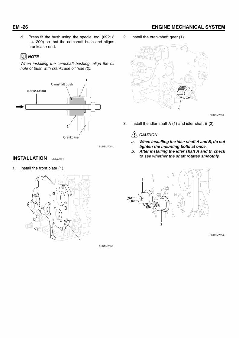
d. Press fit the bush using the special tool (09212- 41200) so that the camshaft bush end alignscrankcase end.
NOTEWhen installing the camshaft bushing, align the oilhole of bush with crankcase oil hole (2).
1
2
09212-41200
Camshaft bush
Crankcase
SUDEM7051L
INSTALLATION EEFAD1F1
1. Install the front plate (1).
1
SUDEM7052L
2. Install the crankshaft gear (1).
1
SUDEM7053L
3. Install the idler shaft A (1) and idler shaft B (2).
CAUTION
a. When installing the idler shaft A and B, do nottighten the mounting bolts at once.
b. After installing the idler shaft A and B, checkto see whether the shaft rotates smoothly.
1
2
SUDEM7054L
TIMING SYSTEM EM -27
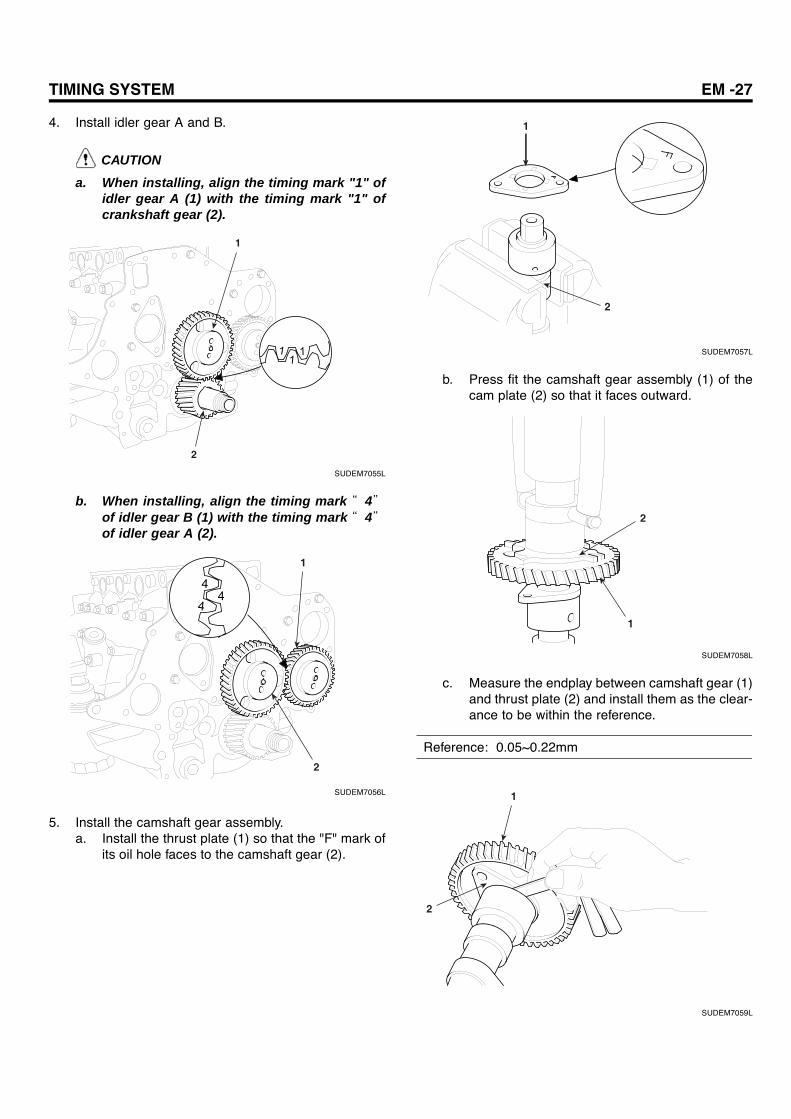
4. Install idler gear A and B.
CAUTIONa. When installing, align the timing mark "1" of
idler gear A (1) with the timing mark "1" ofcrankshaft gear (2).
1
2
SUDEM7055L
b. When installing, align the timing mark “ 4”of idler gear B (1) with the timing mark “ 4”of idler gear A (2).
1
2
SUDEM7056L
5. Install the camshaft gear assembly.a. Install the thrust plate (1) so that the "F" mark of
its oil hole faces to the camshaft gear (2).
1
2
SUDEM7057L
b. Press fit the camshaft gear assembly (1) of thecam plate (2) so that it faces outward.
1
2
SUDEM7058L
c. Measure the endplay between camshaft gear (1)and thrust plate (2) and install them as the clear-ance to be within the reference.
Reference: 0.05~0.22mm
1
2
SUDEM7059L

EM -28 ENGINE MECHANICAL SYSTEM
d. Install the camshaft assembly (1) to thecrankcase.
1
SUDEM7060L
CAUTIONWhen installing, align the timing mark "2" ofcamshaft gear A (1) with the timing mark "2" ofidler gear A (2).
1
2
SUDEM7061L
e. Install the thrust plate (2) mounting bolt (3)through the hole of camshaft cam plate hole (1).
2
31
SUDEM7062L
6. Install the supply pump gear.
CAUTION
When installing, align the timing mark "5" of sup-ply pump (1) with the timing mark "5" of idler gearB (2).
1
2
SUDEM7063L
7. Install the oil pump gear (1).
1
SUDEM7064L
8. Install the front oil seal slinger (1).
1
SUDEM7065L

TIMING SYSTEM EM -29
9. Install the front timing gear case (1).
Tightening torque: 21.6~32.3 Nm(2.2~3.3 kgf.m, 16~24 Ib-ft)
CAUTION
a. Apply the Loctite #5699 or equivalent on theassembly surface of timing gear case (1), andthen assemble it within 3 minutes.
b. Do not start the engine within 1 hour after in-stalling the timing gear case.
1
SUDEM7066L
10. Install the power steering pump (1).
1
SUDEM7067L
11. Install the water pump pulley (1) and water pump as-sembly (2).
2
1
SUDEM7068L
12. Install the crankshaft damper pulley (1) and damperpulley mounting nut (2).
Tightening torque: 588 Nm(60 kgf.m, 436 Ib-ft)
1
2
SUDEM7069L
EM -30 ENGINE MECHANICAL SYSTEM
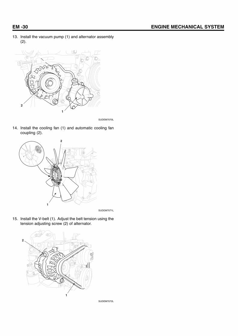
13. Install the vacuum pump (1) and alternator assembly(2).
1
2
SUDEM7070L
14. Install the cooling fan (1) and automatic cooling fancoupling (2).
1
2
SUDEM7071L
15. Install the V-belt (1). Adjust the belt tension using thetension adjusting screw (2) of alternator.
1
2
SUDEM7072L

CYLINDER HEAD ASSEMBLY EM -31
CYLINDER HEADASSEMBLY
COMPONENTS E248774A
1. Engine cover bolt 2. Engine cover 3. Cylinder head cover 4. Cylinder head cover gasket 5. Rocker and bracket assembly 6. Cylinder head bolt 7. Cylinder head assembly 8. Cylinder head gasket 9. Crank case10. Push rod11. Oil filler capTightening Torque : Nm (kgf.m, Ib-ft)
1 2
3
4 Not reusable
5
6
7
8
9
10
11
7.8~11.8(0.8~1.2, 5.8~8.7)
12.7~15.7(1.3~1.6, 9.5~11.6)
147+90(15+90 , 109+90 )
(Not reusable)
SUDEM7073L

EM -32 ENGINE MECHANICAL SYSTEM
12
3
4
5
6
78
9
10
1112
13
14
1. Valve cap2. Valve cotter3. Valve retainer4. Outer side spring5. Inner side spring6. Valve stem seal7. Push rod
8. Cylinder head9. Water director
10. Intake valve11. Exhaust valve12. Cylinder head gasket13. Tappet14. Crankcase
SUDEM7074L

CYLINDER HEAD ASSEMBLY EM -33
REMOVAL EDE5E369
1. Remove the engine cover(1) from the cylinder headcover.
1
SUDEM7280L
2. Remove the glow plug and glow plug plate (1).
1
SUDEM7076L
3. Remove the injection pipe(1) No 1, 2, 3 and 4 runningfrom the common rail assembly to the injector.
1
SUDEM7077L
4. Loosen the hexa-bolt (2) of injector nozzle bridge (1)and remove the injector (3).
1
2
3
SUDEM7078L
5. Remove the oil separator (1) and blow-by hose (2)
2
1
SUDEM7079L
6. Remove the oil level gauge (1).
1
SUDEM7080L

EM -34 ENGINE MECHANICAL SYSTEM
7. Remove the intake manifold assembly (1).
1
2
SUDEM7081L
NOTEDo not remove the actuator (2) of the intake manifoldif its operation is normal.
8. Remove the thermostat housing (1).
1
SUDEM7082L
9. Remove the turbocharger heater protector cover (1)and exhaust manifold heater protector cover (2).
1
2
SUDEM7083L
10. Remove the turbocharger assembly (1) from the cylin-der head.
1
SUDEM7084L
11. Loosen the exhaust manifold mounting nut (1) andthen remove exhaust manifold (2).
1
2
SUDEM7085L
12. Remove the cylinder head cover (1).
1
SUDEM7086L
CYLINDER HEAD ASSEMBLY EM -35
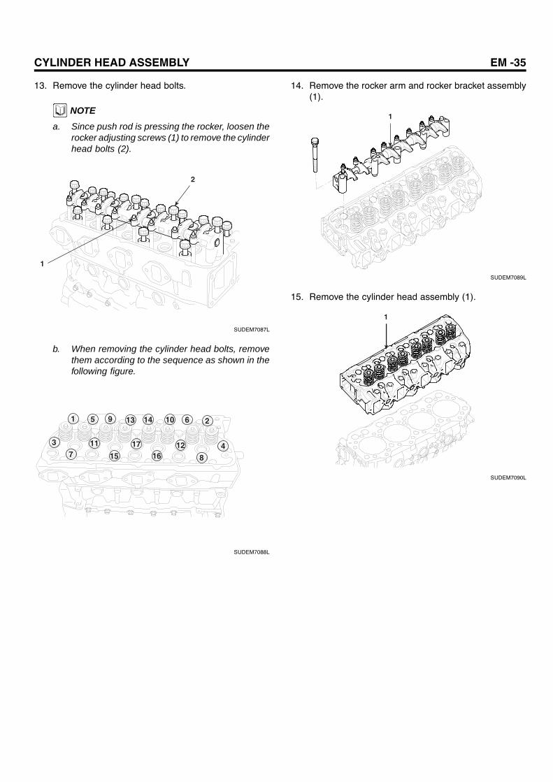
13. Remove the cylinder head bolts.
NOTE
a. Since push rod is pressing the rocker, loosen therocker adjusting screws (1) to remove the cylinderhead bolts (2).
2
1
SUDEM7087L
b. When removing the cylinder head bolts, removethem according to the sequence as shown in thefollowing figure.
8
26
41216
17
15
117
3
1 5 9 13 14 10
SUDEM7088L
14. Remove the rocker arm and rocker bracket assembly(1).
1
SUDEM7089L
15. Remove the cylinder head assembly (1).
1
SUDEM7090L

EM -36 ENGINE MECHANICAL SYSTEM
16. Remove the cylinder head gasket (1).
CAUTIONWhen removing the cylinder head gasket, becareful not to damage the cylinder head andcrankcase.
1
SUDEM7091L
17. Remove the valve tappet (1).
1
SUDEM7092L
DISASSEMBLY ECC7ED4F
ROCKER AND ROCKER SHAFT BRACKETASSEMBLY
1. Remove the set bolt from the front rocker shaftbracket.
2. Remove the front and rear rocker shaft bracket.
3. Remove the rocker assembly.
4. Remove the rocker shaft spring from the rocker shaft.
5. Remove the rocker shaft bracket No.2, 3 and 4 andthen, remove the rocker shaft.
RockerRocker bush
Set bolt
Rocker shaft
Rocker shaft spring
Rocker assembly
Front rocker shaft bracket
Rear rocker shaft bracket
SUDEM7093L
VALVE AND CYLINDER HEAD ASSEMBLY
1. Remove the valve cotter (2) with pushing thevalve spring (1) evenly using the special tool(09222-83300).
2
09222-83300
1
SUDEM7094L

CYLINDER HEAD ASSEMBLY EM -37
2. Remove the retainer (1), valve spring (2), valve stemseal (3) and intake and exhaust valve from the cylinderhead.
CAUTIONValve stem seal should be replaced with new one.
1
2
4
3
SUDEM7095L
3. Remove the water director (1) from the cylinder head.
NOTEIf water director is corroded, remove it. If not, leave it.
1
SUDEM7096L
4. Remove the cylinder gasket (1).
CAUTIONWhen removing the cylinder head gasket, checkthe cylinder head and crankcase for any damage.
1
SUDEM7097L
INSPECTION E5264C2D
1. Check to see whether valve cap (1) and retainer (2)have any irregular wear.
2. Check the intake and exhaust valve (3) for any stuck,crack or damage.
12
3
SUDEM7098L

EM -38 ENGINE MECHANICAL SYSTEM
3. Check the valve tappet (1) for any damage or wear.
1
SUDEM7099L
4. Measure the rocker inner diameter and rocker shaftouter diameter. Replace the bush of rocker, if the gapexceeds the limit.
Items Standard Limit
Inner diameter ofrocker bush
18.980~18.993mm ―
Outer diameter ofrocker shaft
19.05~19.09mm ―
Gap 0.06~0.11mm 0.2mm
SUDEM7100L
5. Inspect the out of squareness (A), free length (B), loadinstalled (C) of valve spring, replace it if any of themexceeds the limit.
Items Standard Limit
Free length 66.1mm 63mm
Loadinstalled
27.9±1.4kg 23.7kg
Outer sideValvespring
Out ofsquareness
1.5mm 2.1mm
Free length 60mm 57mm
Loadinstalled
12.1±0.6kg 10.3kg
Inner sideValvespring
Out ofsquareness
1.5mm 2.1mm
A
B
C
SUDEM7101L
6. Measure the outer diameter of tappet (1) and innerdiameter of crankcase tappet hole (2). Replace thetappet if the gap exceeds the limit.
Reference: 0.045~0.096mmLimit: 0.2mm
1
SUDEM7102L

CYLINDER HEAD ASSEMBLY EM -39
2
SUDEM7103L
7. Measure the run-out of push rod (1). Replace it if itexceeds the limit.
Limit of pushrod run-out: 0.4mm
1
SUDEM7104L
8. Measure the deformation of cylinder head bottomface. If the measurement exceeds the limit, repair itwith surface grinder or replace it.
Flatness of cylinder headReference: 0.05mmLimit: 0.2mm
NOTE
Deformation of cylinder head bottom is measured atthe position as shown in the following figure.
SUDEM7105L
9. Measure the outer diameter of valve stem. If the mea-surement is below the limit, replace the valve stem.
Outer diameter of valve stem― Intake valve
Reference : 8.96~8.97mmLimit : 8.85mm
― Exhaust valveReference : 8.93~8.94mmLimit : 8.85mm
SUDEM7106L
EM -40 ENGINE MECHANICAL SYSTEM
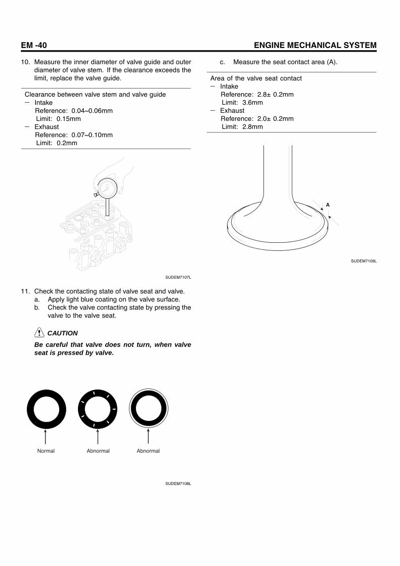
10. Measure the inner diameter of valve guide and outerdiameter of valve stem. If the clearance exceeds thelimit, replace the valve guide.
Clearance between valve stem and valve guide― Intake
Reference: 0.04~0.06mmLimit: 0.15mm
― ExhaustReference: 0.07~0.10mmLimit: 0.2mm
SUDEM7107L
11. Check the contacting state of valve seat and valve.a. Apply light blue coating on the valve surface.b. Check the valve contacting state by pressing the
valve to the valve seat.
CAUTION
Be careful that valve does not turn, when valveseat is pressed by valve.
Normal Abnormal Abnormal
SUDEM7108L
c. Measure the seat contact area (A).
Area of the valve seat contact― Intake
Reference: 2.8± 0.2mmLimit: 3.6mm
― ExhaustReference: 2.0± 0.2mmLimit: 2.8mm
A
SUDEM7109L

CYLINDER HEAD ASSEMBLY EM -41
REPLACEMENT E03FAF94
REPLACEMENT OF ROCKER BUSH
1. Remove the bush from rocker using the special tool(09222-45000).
2. Press fit the bush into rocker using the special tool(09222-45000).
NOTE
When pressing fit bush into rocker, let the chamberside of the rocker be inserted first.
CAUTIONWhen pressing fit, align the bush oil hole withrocker oil hole.
09222-45000
At removing At installing
Rocker chamber
RockerRocker bush
SUDEM7110L
REPALCEMENT OF VALVE GUIDE
Remove the valve guide using the special tool(09221-41100). Install the valve guide using the specialtool (09221-41150, 09221-41100).
09221-4110009221-41150
18mm
At removing At installing
Valve guide
Valve guide
SUDEM7111L
VALVE SEAT REPAIR
1. Repair the valve face using valve refacer (1).
CAUTIONValve seat angle is 45 .
1
SUDEM7112L
2. To repair the valve seat, use the valve seat cutter orvalve seat grinder (1). After grinding, insert the #400or equivalent sand paper between cutter and valveseat and grind lightly.
CAUTIONRepair the valve seat width and valve sinkage tosatisfy the specified limit.
1
SUDEM7113L

EM -42 ENGINE MECHANICAL SYSTEM
3. Install the valve seat using the caulking tool body (1)and locking ring (2).
CAUTIONPress the valve seat (3) with the chamferred sideof the locking ring. And then, caulk it to the cylin-der head as the ring faces the other side.
2
3
1
Installing Caulking
SUDEM7114L
4. Grind the seat width (A) and valve sinkage (B) to bewithin the standard.Valve and valve seat should touch evenly all over thesurface.
Valve seat width (A)Reference: 2.6~3.0mm (Intake)
1.8~2.2mm (Exhaust)Limit: 3.6mm (Intake)
2.8mm (Exhaust)Valve sinkage (B)
Reference: 1.5mmLimit: 1.2mm
A
B
SUDEM7115L
5. Apply the compound evenly over the valve seat sur-face (1).
CAUTION
a. Valve stem (2) should be free from anycompound. Use the medium mesh (meshbetween 120 and 150) compound at firstand finish the grinding with the fine meshcompound (above 200 mesh)
b. Mix the compound with some engine oil toapply evenly.
2
1
SUDEM7116L
6. Place the valve on the valve seat using the valve lap-per (1). Tap the valve with turning the valve slightly.Clean the compound with diesel or equivalent. Applythe engine oil and check whether the contact surfaceis securely positioned.
1
SUDEM7117L
CYLINDER HEAD ASSEMBLY EM -43
REASSEMBLY EBF48CA7
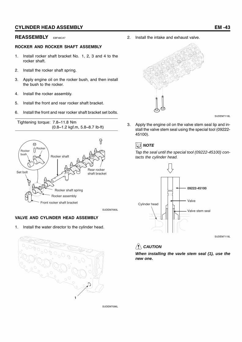
ROCKER AND ROCKER SHAFT ASSEMBLY
1. Install rocker shaft bracket No. 1, 2, 3 and 4 to therocker shaft.
2. Install the rocker shaft spring.
3. Apply engine oil on the rocker bush, and then installthe bush to the rocker.
4. Install the rocker assembly.
5. Install the front and rear rocker shaft bracket.
6. Install the front and rear rocker shaft bracket set bolts.
Tightening torque: 7.8~11.8 Nm(0.8~1.2 kgf.m, 5.8~8.7 Ib-ft)
RockerRocker bush
Set bolt
Rocker shaft
Rocker shaft spring
Rocker assembly
Front rocker shaft bracket
Rear rocker shaft bracket
SUDEM7093L
VALVE AND CYLINDER HEAD ASSEMBLY
1. Install the water director to the cylinder head.
1
SUDEM7096L
2. Install the intake and exhaust valve.
SUDEM7118L
3. Apply the engine oil on the valve stem seal lip and in-stall the valve stem seal using the special tool (09222-45100).
NOTETap the seal until the special tool (09222-45100) con-tacts the cylinder head.
09222-45100
Cylinder headValve
Valve stem seal
SUDEM7119L
CAUTIONWhen installing the vavle stem seal (1), use thenew one.

EM -44 ENGINE MECHANICAL SYSTEM
1
SUDEM7120L
4. Install the retainer, valve spring and valve cotter usingthe special tool (09222-83300).
09222-83300
SUDEM7121L
INSTALLATION EDA3BF2F
1. Assembly is performed in the reverse order of disas-sembly.
2. Installation of cylinder head gasket.
CAUTION
When installing the cylinder head gasket (1),cylinder head installing surface should be freefrom any impurities or foreign materials such asoil.a. Assemble the cylinder head so that "UP"
mark of the cylinder head gasket faces to thecylinder head.
1
SUDEM7097L
b. Selection and assembly of cylinder head gas-ket.Select the cylinder head gasket according tothe piston protrusion amount.
Average pistonprotrusion
Gasketsize
Gasketthickness
0.466~0.526 A 1.35±0.03
0.526~0.588 B 1.40±0.03
0.588~0.648 C 1.45±0.03
Unit : mm
Measuring gauge of piston
protrusion
SUDEM7122L
NOTEIf the max protrusion of the piston is 0.05mm morethan average protrusion, then use the grade up(A→B) gasket.

CYLINDER HEAD ASSEMBLY EM -45
A B C
SUDEM7123L
3. Checking and adjusting of valve clearance
NOTE
Check and adjust the valve clearance while the engineis cold.
1) Crank the engine with the cranking handle andalign the needle to "0" position of crankshaftdamper pulley (side marked with No. 1 through4). Or align it to the "0" position of crankshaftdamper pulley (side marked No. 2 to 3). (This isat the TDC of comopression stroke of cylinderNo. 1).
1
SUDEM7124L
2) At the TDC of compression stroke of cylinder No.1, check and adjust the clearance of the valvewith "O" mark at the following table. And then,turn the crankshaft in one turn to check and ad-just the valve clearance of remaining valves with"X"mark.
Cylin-derNo.
1 2 3 4
ValveIn-take
Ex-haust
In-take
Ex-haust
In-take
Ex-haust
In-take
Ex-haust
TDCof
No.1○ ○ ○ ○
TDCof
No.4× × × ×
3) Measure the clearance between rocker and valvecap using the thickness gauge.a. If the valve clearance exceeds the reference
value, loosen the lock nut (2) and adjust theclearance with thickness gauge by turningthe adjusting screws.
b. After the valve clearance adjustment, fix theadjusting screw using the screw drive (3) andfasten the lock nut securely.
NOTE
Make sure to check whether the valve clearance sat-isfies the reference after valve clearance adjustment.
2
3
1
SUDEM7125L

EM -46 ENGINE MECHANICAL SYSTEM
CRANKCASE
FLYWHEEL
COMPONENTS E60B5C72
12
3
4
5
7
6
7
8
1. Front plate2. Gasket3. Crankcase4. Rear plate5. Rear oil seal6. Pilot bearing7. Flywheel8. Flywheel mounting bolt
39.2+40(4+40 , 29.1+40 )
Tightening Torque : Nm (kgf.m, Ib-ft)
SUDEM7126L
CRANKCASE EM -47
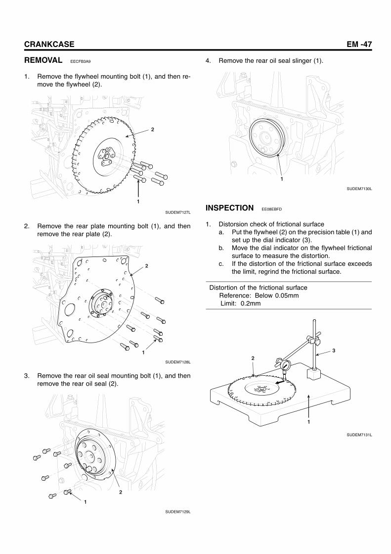
REMOVAL EECFB3A9
1. Remove the flywheel mounting bolt (1), and then re-move the flywheel (2).
2
1
SUDEM7127L
2. Remove the rear plate mounting bolt (1), and thenremove the rear plate (2).
2
1
SUDEM7128L
3. Remove the rear oil seal mounting bolt (1), and thenremove the rear oil seal (2).
2
1
SUDEM7129L
4. Remove the rear oil seal slinger (1).
1
SUDEM7130L
INSPECTION EE08EBFD
1. Distorsion check of frictional surfacea. Put the flywheel (2) on the precision table (1) and
set up the dial indicator (3).b. Move the dial indicator on the flywheel frictional
surface to measure the distortion.c. If the distortion of the frictional surface exceeds
the limit, regrind the frictional surface.
Distortion of the frictional surfaceReference: Below 0.05mmLimit: 0.2mm
23
1
SUDEM7131L

EM -48 ENGINE MECHANICAL SYSTEM
2. Repair of the frictional surfaceRepair the frictional surface with the surface grinder.
CAUTIONa. After repairing the frictional surface, check
whether the frictional surface is parallel withsurface A within 0.1mm.
b. Check the frictional surface (size B) whetherits height is within the limit.
Height to the frictional surface (B)Reference: 24.5mmLimit: 23.5mm
B
A
SUDEM7132L
3. Replacement of flywheel ring geara. When removing the ring gear (1), heat the ring
gear evenly using acetylene torch or equivalenttools and then remove the ring gear by tappingthe circumference with rod or hammer.
b. When installing, heat the ring gear with pistonheater for 3 minutes (about 100 C). And then,insert the ring gear so that the un-chamfered gearfaces to flywheel.
1
The chamfer was machined.
SUDEM7279L
INSTALLATION E561D9B1
1. Install the rear oil seal slinger using the special tool(09211-41000).
09211-41000
SUDEM7133L
09211-41000
19.7mm
Dowel pin
CrankshaftRear oil seal slinger
SUDEM7134L
CRANKCASE EM -49
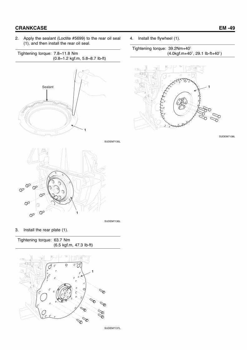
2. Apply the sealant (Loctite #5699) to the rear oil seal(1), and then install the rear oil seal.
Tightening torque: 7.8~11.8 Nm(0.8~1.2 kgf.m, 5.8~8.7 Ib-ft)
1
Sealant
SUDEM7135L
1
SUDEM7136L
3. Install the rear plate (1).
Tightening torque: 63.7 Nm(6.5 kgf.m, 47.3 Ib-ft)
1
SUDEM7137L
4. Install the flywheel (1).
Tightening torque: 39.2Nm+40(4.0kgf.m+40 , 29.1 Ib-ft+40 )
1
SUDEM7138L
EM -50 ENGINE MECHANICAL SYSTEM
CYLINDER BLOCK ASSEMBLY
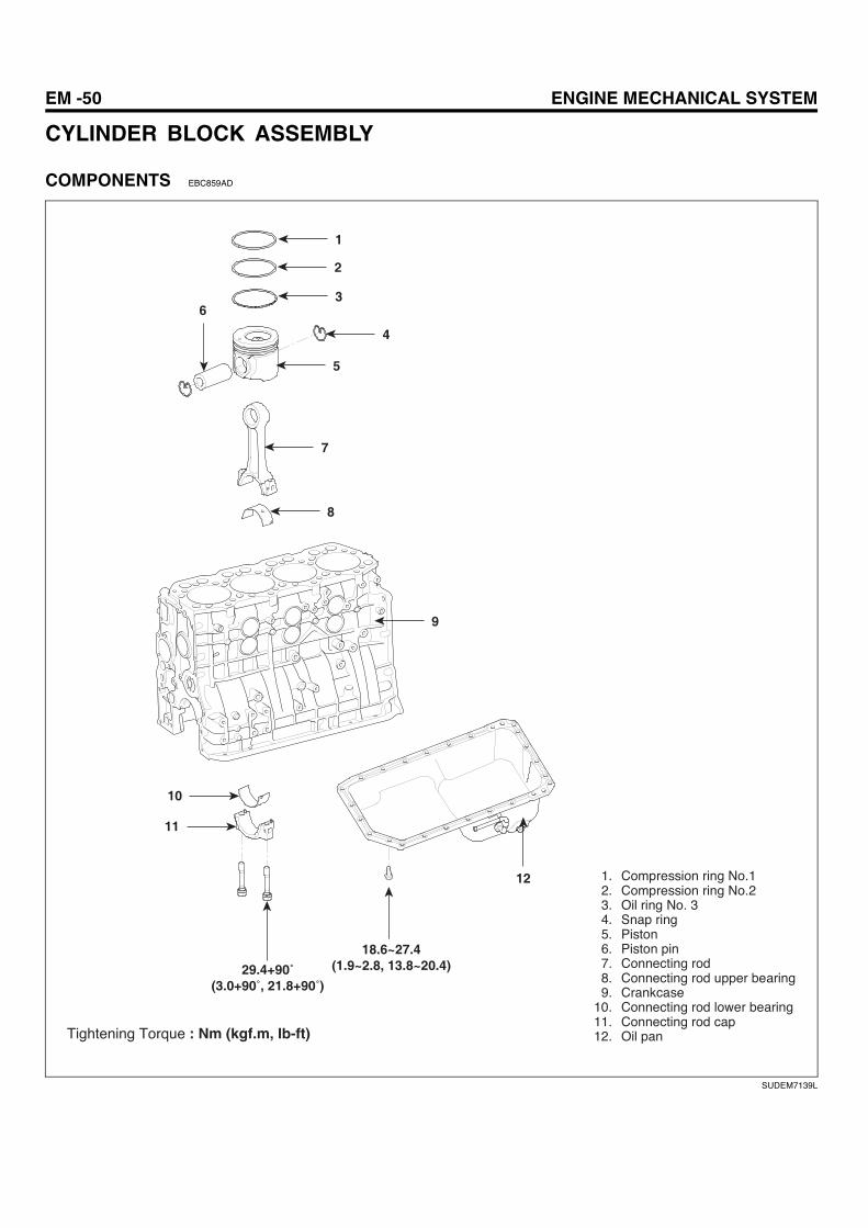
COMPONENTS EBC859AD
1
2
3
4
5
7
8
9
12
18.6~27.4(1.9~2.8, 13.8~20.4)
10
11
6
1. Compression ring No.12. Compression ring No.23. Oil ring No. 34. Snap ring5. Piston6. Piston pin7. Connecting rod8. Connecting rod upper bearing9. Crankcase
10. Connecting rod lower bearing11. Connecting rod cap12. Oil panTightening Torque : Nm (kgf.m, Ib-ft)
29.4+90(3.0+90 , 21.8+90 )
SUDEM7139L
CRANKCASE EM -51
1
2
29.4 (3.0, 21.8)
3
4
5
6
7
12
588 (60.0, 436)
1110
9 8
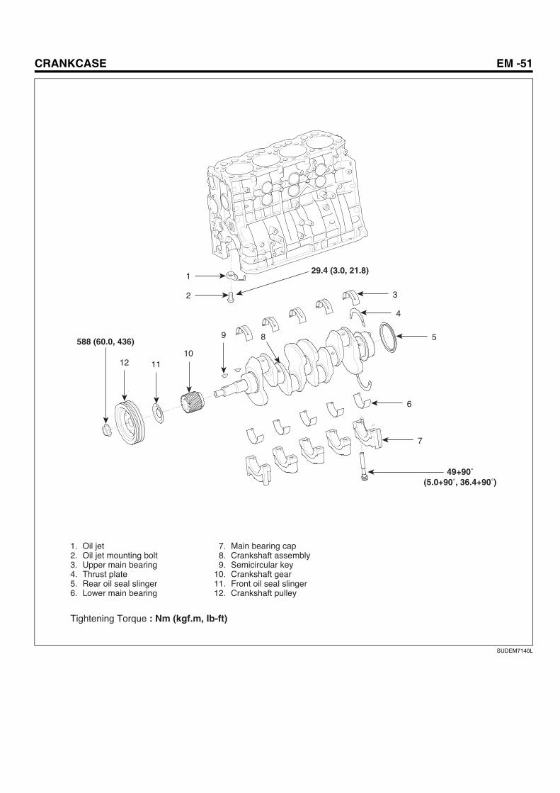
1. Oil jet2. Oil jet mounting bolt3. Upper main bearing4. Thrust plate5. Rear oil seal slinger6. Lower main bearing
7. Main bearing cap8. Crankshaft assembly9. Semicircular key
10. Crankshaft gear11. Front oil seal slinger12. Crankshaft pulley
Tightening Torque : Nm (kgf.m, Ib-ft)
49+90(5.0+90 , 36.4+90 )
SUDEM7140L

EM -52 ENGINE MECHANICAL SYSTEM
REMOVAL EE4DAE0F
1. Remove the engine and transaxle.
2. Remove the flywheel and rear plate.
3. Remove the intake and exhaust manifold.
4. Remove e the cylinder head assembly.
5. Remove the supply pump (1) and common rail assem-bly (2).
1
2
SUDEM7281L
6. Remove the V-belt (1) and remove the alternator as-sembly (2).
2
1
SUDEM7142L
7. Align the timing mark (2~3 side) of crankshaft damperpulley to the compression TDC of cylinder No. 1.
NOTEAs for the removal of cooling fan pulley, crankshaftdamper pulley and timing gear case, refer to the re-moval procedure of timing system.
SUDEM7143L
8. Remove oil cooler assembly.
1
SUDEM7144L
9. Remove timing gear train [(oil pump gear (6),camshaft assembly (2), idler gear A (3), idler supplypump gear (5)), and then remove front plate.
5
4
3
2
6 1
SUDEM7145L
CRANKCASE EM -53
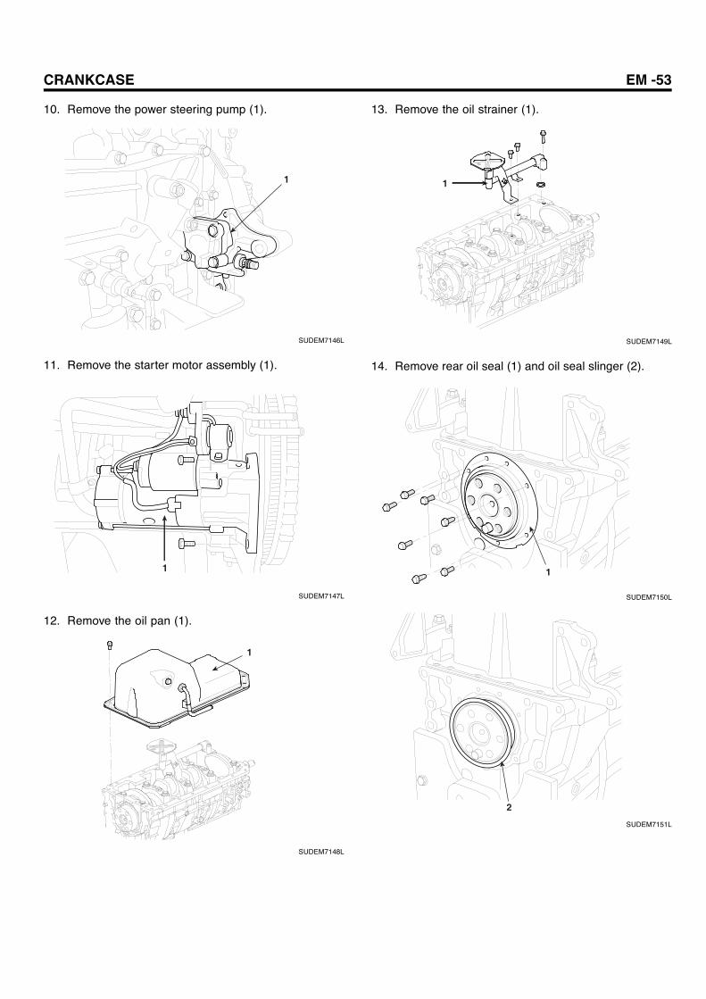
10. Remove the power steering pump (1).
1
SUDEM7146L
11. Remove the starter motor assembly (1).
1
SUDEM7147L
12. Remove the oil pan (1).
1
SUDEM7148L
13. Remove the oil strainer (1).
1
SUDEM7149L
14. Remove rear oil seal (1) and oil seal slinger (2).
1
SUDEM7150L
2
SUDEM7151L

EM -54 ENGINE MECHANICAL SYSTEM
15. Remove the connecting rod bearing cap (1).
NOTEMake marks at the connecting rod and cap to be re-assembled correctly.
1
SUDEM7152L
16. Remove the piston and connecting rod assembly (1)from cylinder block.
1
SUDEM7153L
17. Remove the front, rear and main bearing caps.a. Remove the front bearing cap and rear end bear-
ing cap. Remove the thrust plate (2) from therear-bearing cap (1).
b. Remove the main bearing cap (1) and bearing(3).
1
2
3
SUDEM7154L
18. Remove the crankshaft (1) from the cylinder block.
CAUTION
Handle the crankshaft carefully so that the journalis not damaged.
1
SUDEM7155L
19. Remove the oil jet (1) from the cylinder block.
1
SUDEM7156L

CRANKCASE EM -55
DISASSEMBLY E190BEAB
PISTON AND CONNECTING ROD ASSEMBLY
1. Remove the piston ring using the special tool (09222-83200).
09222-83200
SUDEM7157L
2. Remove the piston pin snap ring (2) using the snapring pliers (1).
1
2
SUDEM7158L
3. Remove the piston pin (1) from the piston.
1
SUDEM7159L
4. Remove the connecting rod (1) from the piston.
1
SUDEM7160L
INSPECTION EBE61DCA
CYLINDER BLOCK
NOTE
a. Before repairing, clean each part to remove dust,oil, carbon and fur.
b. Before cleaning the cylinder block, check waterleakage or damages.
c. Remove the adhesives at each oil hole using airbrush and check whether any hole is clogged.
1. In addition to the visual check about scratch, rust andcorrosion, inspect the slight scratches with precipi-tant. Repair or replace it if needed.
2. Measure the twist of cylinder block using straight edge(1) and thickness gauge (2). Measure them by placingthe straight edge as shown in the following figure.
NOTEWhen measuring, cylinder upper block should be freefrom foreign materials such as gasket piece.
CAUTION
When grinding the cylinder block, grind it as thepiston protrusion does not exceed the reference.

EM -56 ENGINE MECHANICAL SYSTEM
Flatness figure of cylinder blockReference : Below 0.07mmLimit : 0.2mm
1
2
SUDEM7161L
3. Check the cylinder wall to see if it is cracked or dam-aged. If it is abnormal, repair (oversize) or replace thecylinder sleeve.
4. Measure the cylinder sleeve ID using the cylindergauge. If it is excessively worn, repair it with oversizeand replace the piston and piston ring.
Clearance between piston and cylinder sleeve :0.080~0.130mm
CAUTION
1. When replacing piston, piston ring should bereplaced together.
2. Even if only one cylinder needs boring, allcylinder walls should be grinded with over-size at the same time.
3. Measure the most seriously worn cylinderwall and select the oversize based on themeasurement.
4. Available oversizes are +0.25, +0.50, +0.75and +1.00.
5. Piston and connection rod should be re-placed with the new one which has identicalweight and grade with the old one.
a. Measure the inner diameter of cylinder sleeve us-ing the cylinder gauge (1).
Inner diameter of cylinder sleeve: 104.00~104.03mm
1
SUDEM7162L
b. Measure the outer diameter of piston skirt at theposition, which is 85mm down from the upper pis-ton.
Outer diameter of piston: 103.91~103.92mm
SUDEM7163L
CRANKCASE EM -57
PISTON
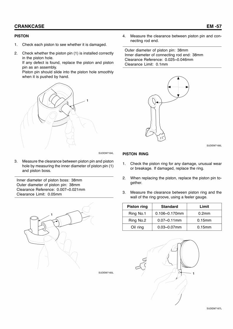
1. Check each piston to see whether it is damaged.
2. Check whether the piston pin (1) is installed correctlyin the piston hole.If any defect is found, replace the piston and pistonpin as an assembly.Piston pin should slide into the piston hole smoothlywhen it is pushed by hand.
1
SUDEM7164L
3. Measure the clearance between piston pin and pistonhole by measuring the inner diameter of piston pin (1)and piston boss.
Inner diameter of piston boss: 38mmOuter diameter of piston pin: 38mmClearance Reference: 0.007~0.021mmClearance Limit: 0.05mm
1
SUDEM7165L
4. Measure the clearance between piston pin and con-necting rod end.
Outer diameter of piston pin: 38mmInner diameter of connecting rod end: 38mmClearance Reference: 0.025~0.046mmClearance Limit: 0.1mm
SUDEM7166L
PISTON RING
1. Check the piston ring for any damage, unusual wearor breakage. If damaged, replace the ring.
2. When replacing the piston, replace the piston pin to-gether.
3. Measure the clearance between piston ring and thewall of the ring groove, using a feeler gauge.
Piston ring Standard Limit
Ring No.1 0.106~0.170mm 0.2mm
Ring No.2 0.07~0.11mm 0.15mm
Oil ring 0.03~0.07mm 0.15mm
1
SUDEM7167L

EM -58 ENGINE MECHANICAL SYSTEM
4. After installing the piston ring to the cylinder bore,push the piston ring to the vertical direction with thepiston.
Piston ring end gapRing No.1: 0.25~0.40mmRing No.2: 0.50~0.65mmOil ring: 0.20~0.40mm
SUDEM7168L
CRANKSHAFT
1. Measure the endplay of crankshaft.
Crankshaft endplayReference :0.10~0.26mmLimit: 0.4mm
a. If the endplay exceeds the limit, replace the thrustplate with the oversize.
b. Oversizes of the thrust plate are +0.15, +0.30,and +0.45.
SUDEM7169L
2. Measure the oil gap of crankshaft main bearing.a. Remove the main bearing cap.b. Measure the oil gap of main bearing.
1) Remove the oil or other foreign materials frommain journal and main bearing surface.
2) Place the plastic gauge along with the shaft di-rection of the journal.
CRANKCASE EM -59
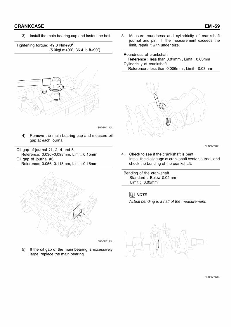
3) Install the main bearing cap and fasten the bolt.
Tightening torque: 49.0 Nm+90(5.0kgf.m+90 , 36.4 Ib-ft+90 )
SUDEM7170L
4) Remove the main bearing cap and measure oilgap at each journal.
Oil gap of journal #1, 2, 4 and 5Reference: 0.036~0.098mm, Limit: 0.15mm
Oil gap of journal #3Reference: 0.056~0.118mm, Limit: 0.15mm
SUDEM7171L
5) If the oil gap of the main bearing is excessivelylarge, replace the main bearing.
3. Measure roundness and cylindricity of crankshaftjournal and pin. If the measurement exceeds thelimit, repair it with under size.
Roundness of crankshaftReference : less than 0.01mm , Limit : 0.03mm
Cylindricity of crankshaftReference : less than 0.006mm , Limit : 0.03mm
SUDEM7172L
4. Check to see if the crankshaft is bent.Install the dial gauge of crankshaft center journal, andcheck the bending of the crankshaft.
Bending of the crankshaftStandard : Below 0.02mmLimit : 0.05mm
NOTE
Actual bending is a half of the measurement.
SUDEM7173L

EM -60 ENGINE MECHANICAL SYSTEM
CONNECTING ROD BEARING
1. Before removing the connecting rod cap, measure theconnecting rod endplay. If the gap exceeds the refer-ence, replace the connecting rod.
Connecting rod endplayReference: 0.15~0.45mmLimit: 0.6mm
SUDEM7174L
2. Measure the oil gap of the connecting rod bearing.
1) Remove the connecting rod cap.
2) Measure the oil gap of the connecting rod bear-ing.a. Remove the oil or foreign materials from pin
journal and connecting rod bearing surface.b. Place the plastic gauge on the shaft of pin
journal along with its direction.c. Install the connecting rod bearing cap and
fasten the bolt.
Tightening torque: 29.4 Nm+90(3.0kgf.m+90 , 21.8 Ib-ft+90 )
SUDEM7175L
d. Remove the connecting rod bearing cap andmeasure the oil gap at each pin journal.
Connecting rod oil gapReference: 0.040~0.099mmLimit: 0.2mm
SUDEM7176L
e. If the oil gap is excessively large, replace theconnecting rod bearing.
3. Length of the connecting rod bearing.Length of the Connecting rod bearing (1) is measuredat the free state. If the measurement is below the limit,replace the upper and lower bearing.
Length of the connecting rod bearingLimit: above 69.5mm
CAUTION
Bearing should not be artificially expanded toreuse.
1
SUDEM7177L
CRANKCASE EM -61
REASSEMBLY E49D5D90
PISTON AND CONNECTING ROD ASSEMBLY
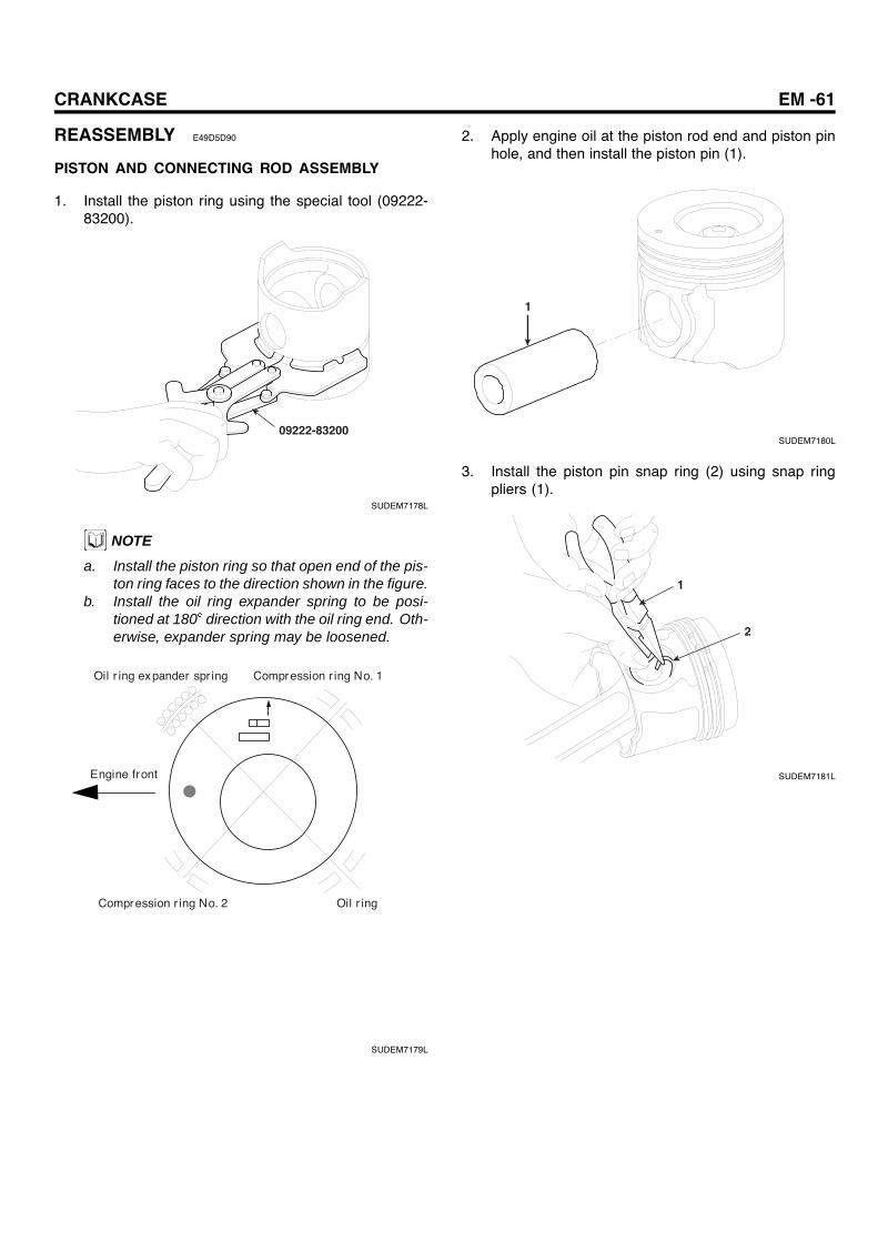
1. Install the piston ring using the special tool (09222-83200).
09222-83200
SUDEM7178L
NOTE
a. Install the piston ring so that open end of the pis-ton ring faces to the direction shown in the figure.
b. Install the oil ring expander spring to be posi-tioned at 180 direction with the oil ring end. Oth-erwise, expander spring may be loosened.
Oil r ing expander spr ing
Compression r ing No. 1
Engine front
Compression r ing No. 2
Oil r ing
SUDEM7179L
2. Apply engine oil at the piston rod end and piston pinhole, and then install the piston pin (1).
1
SUDEM7180L
3. Install the piston pin snap ring (2) using snap ringpliers (1).
1
2
SUDEM7181L

EM -62 ENGINE MECHANICAL SYSTEM
INSTALLATION EE5ABFA8
1. Install oil jet (1) to the cylinder block.
1
SUDEM7182L
2. Install thrust plate (1) and upper main bearing (2) tothe crankcase.
CAUTIONa. Install the thrust plate with the oil grooveless
side toward the crankcase.b. Align the lug groove of crankcase with the lug
of main bearing.c. Since there is oil hole at upper bearing, take
care not to be interchanged with lower bear-ing.
d. Apply engine oil on the all over the slidingsurface.
2
1
SUDEM7183L
3. Install the crankshaft (1) to the cylinder block.
CAUTION
Handle crankshaft carefully not to be damaged.
1
SUDEM7184L
4. Install the front, rear and main bearing caps.a. Insert the lower main bearing (1) into bearing cap
(2).
NOTE
Check to see whether the main bearing lug matchesmain bearing cap lug groove.
b. Install thrust plate (3) to the rear-bearing cap.
2
1
3
SUDEM7185L
CRANKCASE EM -63
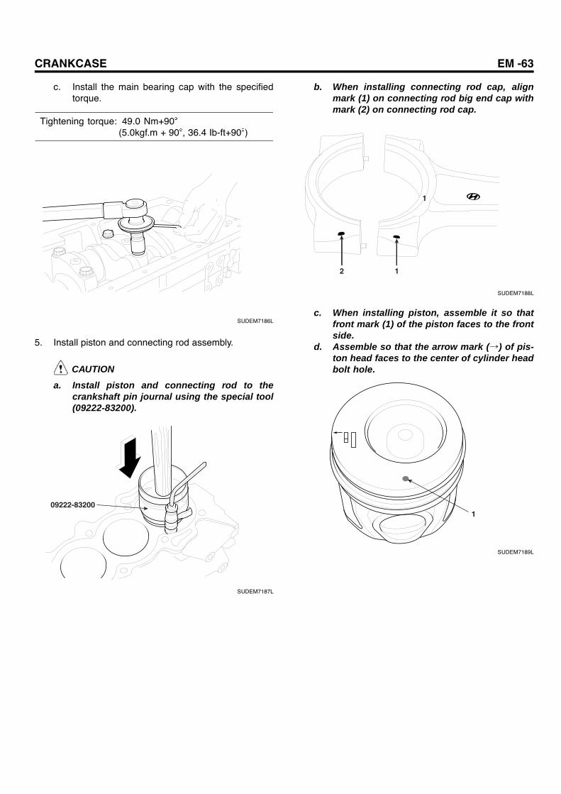
c. Install the main bearing cap with the specifiedtorque.
Tightening torque: 49.0 Nm+90(5.0kgf.m + 90 , 36.4 Ib-ft+90 )
SUDEM7186L
5. Install piston and connecting rod assembly.
CAUTION
a. Install piston and connecting rod to thecrankshaft pin journal using the special tool(09222-83200).
09222-83200
SUDEM7187L
b. When installing connecting rod cap, alignmark (1) on connecting rod big end cap withmark (2) on connecting rod cap.
1
2 1
SUDEM7188L
c. When installing piston, assemble it so thatfront mark (1) of the piston faces to the frontside.
d. Assemble so that the arrow mark (→) of pis-ton head faces to the center of cylinder headbolt hole.
1
SUDEM7189L

EM -64 ENGINE MECHANICAL SYSTEM
e. Tighten the connecting rod cap with specifiedtorque.
Tightening torque: 29.4 Nm+90(3.0kgf.m + 90 , 21.8 Ib-ft+90 )
SUDEM7190L
6. Install rear oil seal slinger using the special tool(09211-41000).
09211-41000
SUDEM7191L
7. Apply the sealant (Loctite #5699) to the rear oil seal,and then install the rear oil seal (1).
1
SUDEM7192L
8. Install the oil strainer (1).
1
SUDEM7193L
CRANKCASE EM -65
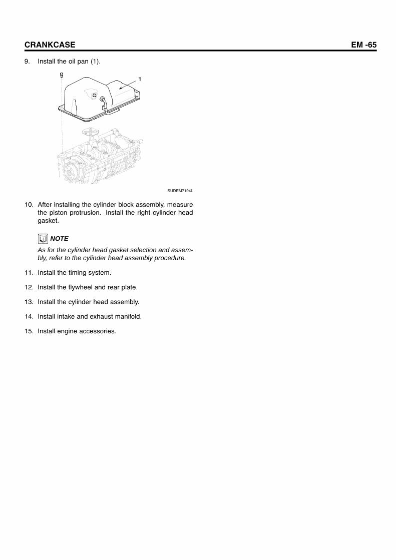
9. Install the oil pan (1).
1
SUDEM7194L
10. After installing the cylinder block assembly, measurethe piston protrusion. Install the right cylinder headgasket.
NOTE
As for the cylinder head gasket selection and assem-bly, refer to the cylinder head assembly procedure.
11. Install the timing system.
12. Install the flywheel and rear plate.
13. Install the cylinder head assembly.
14. Install intake and exhaust manifold.
15. Install engine accessories.
EM -66 ENGINE MECHANICAL SYSTEM
INTAKE AND EXHAUSTSYSTEM
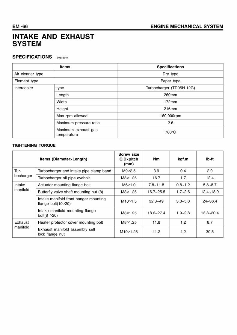
SPECIFICATIONS E08C8904
Items Specifications
Air cleaner type Dry type
Element type Paper type
type Turbocharger (TD05H-12G)
Length 260mm
Width 172mm
Height 216mm
Max rpm allowed 160,000rpm
Maximum pressure ratio 2.6
Intercooler
Maximum exhaust gastemperature 760 C
TIGHTENING TORQUE
Items (Diameter×Length)Screw sizeO.D×pitch
(mm)Nm kgf.m Ib-ft
Turbocharger and intake pipe clamp band M9×2.5 3.9 0.4 2.9Tur-bocharger Turbocharger oil pipe eyebolt M8×1.25 16.7 1.7 12.4
Actuator mounting flange bolt M6×1.0 7.8~11.8 0.8~1.2 5.8~8.7
Butterfly valve shaft mounting nut (8) M8×1.25 16.7~25.5 1.7~2.6 12.4~18.9
Intake manifold front hanger mountingflange bolt(10×20)
M10×1.5 32.3~49 3.3~5.0 24~36.4
Intakemanifold
Intake manifold mounting flangebolt(8 ×20)
M8×1.25 18.6~27.4 1.9~2.8 13.8~20.4
Heater protector cover mounting bolt M8×1.25 11.8 1.2 8.7Exhaustmanifold Exhaust manifold assembly self
lock flange nutM10×1.25 41.2 4.2 30.5

INTAKE AND EXHAUST SYSTEM EM -67
TROUBLESHOOTING EBA6A66F
Output drop
Intake system
Exhaust system
Is air cleaner clogged?
Does air leak at the connection of intake system?
Replace the element
Repair
Repair
* Is muffler or exhaust pipe deformed?
* Is carbon accumulated?Repair or replace
Repair or replace
Does gas leak at exhaust system?
Is exhaust brake opened?
Yes
Yes
Yes
Yes
Yes
Yes
Yes
No
Turbocharger (TD05H-12G)
If the turbocharger is defective, replace it in the assembly unit.
Any leakage at the connection of compressor cover and intake pipe?
Tighten the clamp
Are compressor inside, compressor cover and compressor wheel polluted?
Cleaning
Does turbine wheel rotate smoothly if turned by hands?
Clean the carbon depo-sit and turbocharger.
No
No
No
No
No
SUDEM7195L

EM -68 ENGINE MECHANICAL SYSTEM
Intake system
Exhaust system
Repair or replace
Repair or replace
No
No
Yes
No
No
Yes
Turbocharger
Yes
Yes
Yes
Yes
Unusual noise and vibration
Are fixing bolts and nuts of intake system fastened securely?
Are fixing bolts and nuts of exhaust system fastened securely
Is exhaust pipe or muffler damaged?
Tighten
Are bearing and rotating parts OK?
Do rotating parts rotate smoothly? Isn't turbine wheel shaft bent?
Are there any foreign materialsin turbocharger?
Check the intake and exh-aust piper carefully for the chip of compressor or turb-ine wheel
Defective bearing Compressor wheel or tur-
bine wheel damage due to the foreign materials inside.
Inspect the following. Deterioration of engine oil Oil filter element clogging Foreign materials in oil
supply pipe. Bearing damage due to
repeated sudden departures and stops.
SUDEM7196L
INTAKE AND EXHAUST SYSTEM EM -69
TURBOCHARGER
COMPONENTS E2B39DEE
10
9
11 40.2 (4.1, 29.8)
11.8 (1.2, 8.7)7
6
54
3
2
1
41.2 (4.2, 30.5)
8
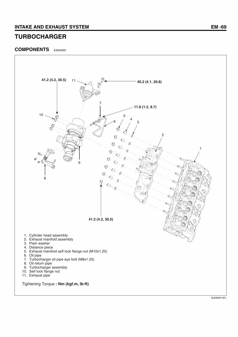
1. Cylinder head assembly2. Exhaust manifold assembly3. Plain washer4. Distance piece5. Exhaust manifold self lock flange nut (M10x1.25)6. Oil pipe7. Turbocharger oil pipe eye bolt (M8x1.25)8. Oil return pipe9. Turbocharger assembly
10. Self lock flange nut11. Exhaust pipe
Tightening Torque : Nm (kgf.m, Ib-ft)
41.2 (4.2, 30.5)
SUDEM7197L

EM -70 ENGINE MECHANICAL SYSTEM
3
5
4
6
7
2
1
3.9~4.9(0.4~0.5, 2.9~3.6)
1. Actuator2. Compressor cover3. O-ring4. Cartridge assembly5. Snap ring6. Coupling7. Turbine housing
Tightening Torque : Nm (kgf.m, Ib-ft)
SUDEM7198L

INTAKE AND EXHAUST SYSTEM EM -71
REMOVAL E90F3479
1. Remove the turbocharger heater protector cover (1).
1
SUDEM7199L
2. Remove the turbocharger assembly (1).
1
SUDEM7200L
3. Make an aligning mark on the coupling (1), turbinehousing (2), compressor cover (3), and cartridge as-sembly (4).
1
2
3
4
SUDEM7201L
4. Remove the turbine housing(1).
CAUTION
a. Lightly tap the housing circumference withrubber hammer so that turbine housing is notdamaged.
b. Since turbine wheel blade is easily bent, ex-ercise care when removing the housing.
1
SUDEM7202L
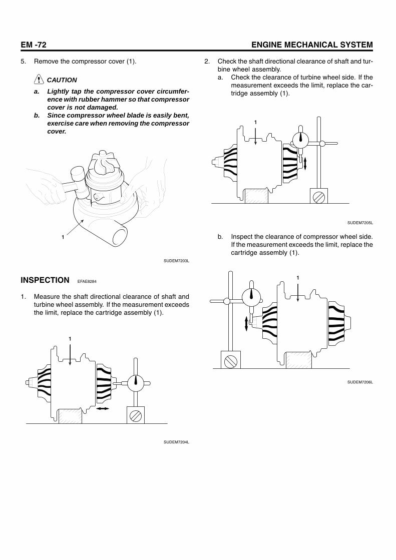
EM -72 ENGINE MECHANICAL SYSTEM
5. Remove the compressor cover (1).
CAUTION
a. Lightly tap the compressor cover circumfer-ence with rubber hammer so that compressorcover is not damaged.
b. Since compressor wheel blade is easily bent,exercise care when removing the compressorcover.
1
SUDEM7203L
INSPECTION EFAE8284
1. Measure the shaft directional clearance of shaft andturbine wheel assembly. If the measurement exceedsthe limit, replace the cartridge assembly (1).
1
SUDEM7204L
2. Check the shaft directional clearance of shaft and tur-bine wheel assembly.a. Check the clearance of turbine wheel side. If the
measurement exceeds the limit, replace the car-tridge assembly (1).
1
SUDEM7205L
b. Inspect the clearance of compressor wheel side.If the measurement exceeds the limit, replace thecartridge assembly (1).
1
SUDEM7206L

INTAKE AND EXHAUST SYSTEM EM -73
3. After assembling the turbocharger assembly (1), turneach wheel (2) to see if it rotates smoothly.
2
1
SUDEM7207L
4. When assembling turbocharger assembly (1), fill withthe engine oil through the oil hole (2) so that each partoperates smoothly.
2
1
SUDEM7208L
INSTALLATION E50867FF
1. When assembling the snap ring (1) to compressorcover (2), assemble it so that the snap ring taper side(3) faces up.
CAUTION
When installing the snap ring, install it to the com-pressor cover by holding the snap with one hand.
21
3
SUDEM7209L
2. Install the turbocharger assembly (1).
Tightening torque: 41.2 Nm(4.2kgf.m, 30.5 Ib-ft)
1
SUDEM7210L

EM -74 ENGINE MECHANICAL SYSTEM
3. Install the turbocharger heater protector cover (1).
Tightening torque: 11.8 Nm(1.2kgf.m, 8.7 Ib-ft)
1
SUDEM7211L
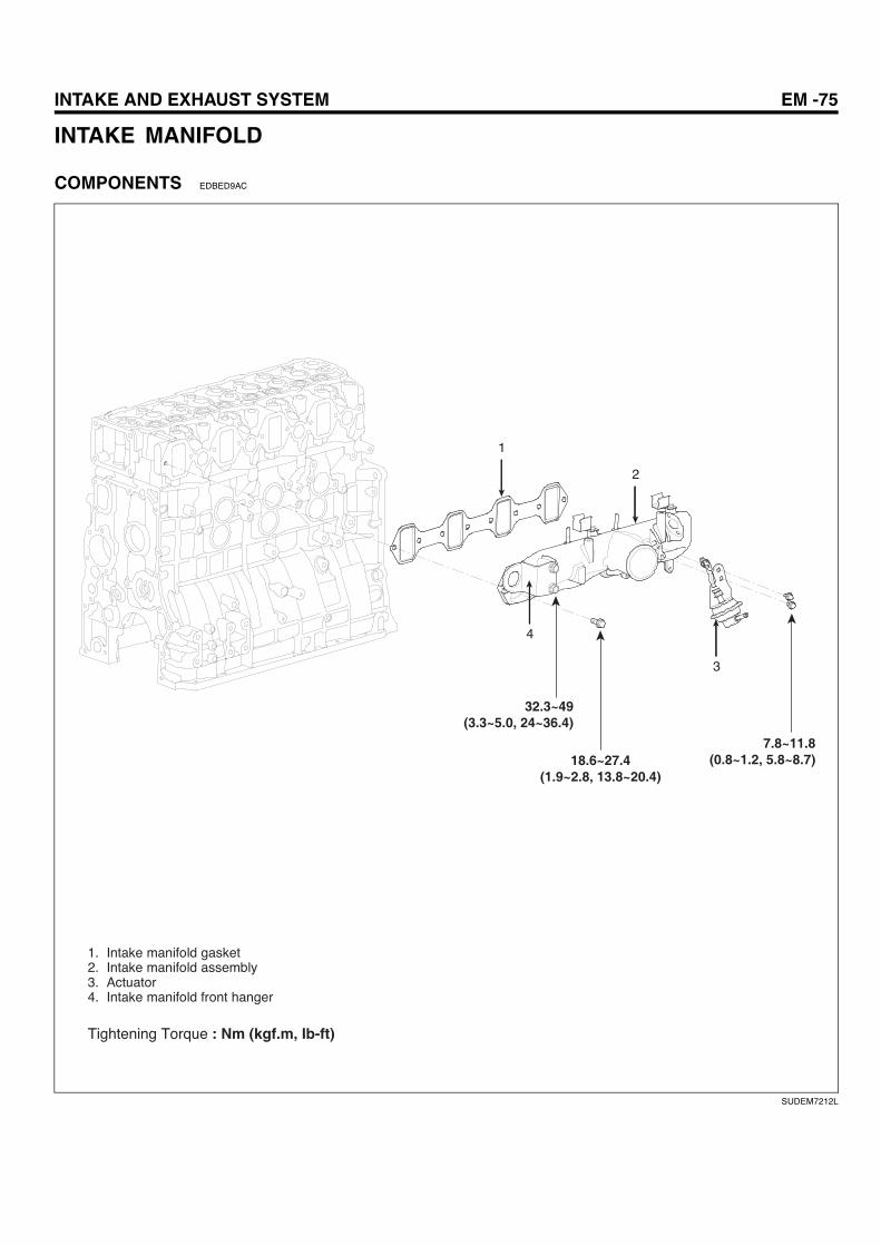
INTAKE AND EXHAUST SYSTEM EM -75
INTAKE MANIFOLD
COMPONENTS EDBED9AC
1
2
3
4
32.3~49(3.3~5.0, 24~36.4)
18.6~27.4(1.9~2.8, 13.8~20.4)
7.8~11.8(0.8~1.2, 5.8~8.7)
1. Intake manifold gasket2. Intake manifold assembly3. Actuator4. Intake manifold front hanger
Tightening Torque : Nm (kgf.m, Ib-ft)
SUDEM7212L

EM -76 ENGINE MECHANICAL SYSTEM
REMOVAL EEA818FD
1. Remove the injection pipe (1) No. 1,2,3 and 4 fromcommon rail assembly to the injector.
1
SUDEM7213L
2. Remove the Intake manifold assembly (1).
1
SUDEM7214L
INSPECTION EEC01B88
Inspection and adjustment of the clearance between but-terfly valve and Intake manifold
1. Secure the butterfly valve to the close state with500mmHg or more negative pressure applied to theactuator (the condition that double nuts are coherentto the bracket).
2. Adjust the clearance by moving the adjusting hole (A)of actuator bracket and tighten it with the bolt.
Clearance between butterfly valve andIntake manifold (B):4.0~4.5mm
B
A
Double nut
Actuator
SUDEM7215L
3. When the internal air pressure of 3kg/cm² is appliedto the actuator, it should maintain the airtight of 0.1ccor less for 5 seconds.
4. Butterfly valve should have the durability of 400,000cycles at the ambient temperature of 80 C.

INTAKE AND EXHAUST SYSTEM EM -77
INSTALLATION EE8BA5EE
1. Install the intake manifold (1).
Tightening torque: 18.6~27.4 Nm(1.9~2.8kgf.m, 13.8~20.4 Ib-ft)
1
1.9~2.8
0.8~1.2
SUDEM7216L
1
2
1.5mm
0.5kgf•m
SUDEM7217L
NOTE
When installing the butterfly valve (1), fasten the but-terfly valve shaft mounting nut (2) so that the identi-fication mark (▽) faces to the direction shown in theillustration.
Tightening torque: 16.7~25.5 Nm(1.7~2.6kgf.m, 12.4~18.9 Ib-ft)
2. Install the injection pipe (1) No.1, 2,3 and 4.
Tightening torque: 39.2~49 Nm(4.0~5.0kgf.m, 29.1~36.4 Ib-ft)
1
SUDEM7218L

EM -78 ENGINE MECHANICAL SYSTEM
EXHAUST MANIFOLD
COMPONENTS E6A9EE49
65
4
3
21
41.2 (4.2, 30.5)
1. Cylinder head assembly2. Exhaust manifold gasket3. Exhaust manifold assembly4. Plain washer5. Distance piece6. Exhaust manifold self lock flange nut (M10x1.25)
Tightening Torque : Nm (kgf.m, Ib-ft)
SUDEM7219L
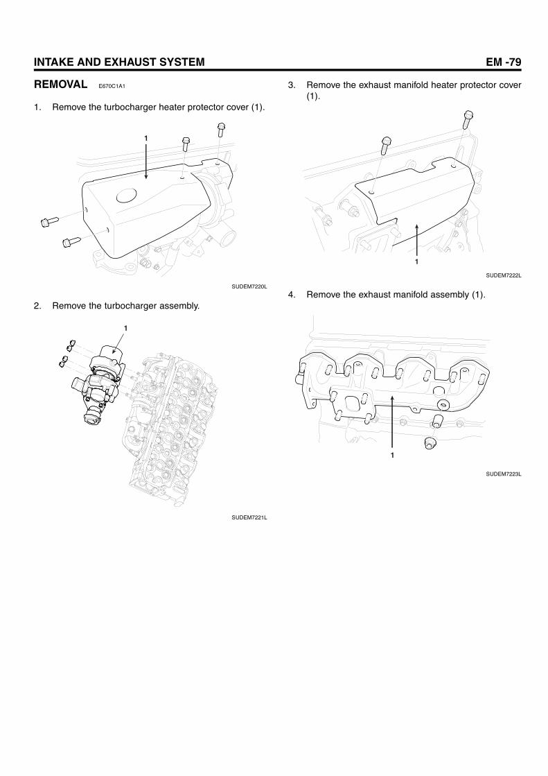
INTAKE AND EXHAUST SYSTEM EM -79
REMOVAL E670C1A1
1. Remove the turbocharger heater protector cover (1).
1
SUDEM7220L
2. Remove the turbocharger assembly.
1
SUDEM7221L
3. Remove the exhaust manifold heater protector cover(1).
1
SUDEM7222L
4. Remove the exhaust manifold assembly (1).
1
SUDEM7223L

EM -80 ENGINE MECHANICAL SYSTEM
INSTALLATION EFDF4E9E
1. Install the exhaust manifold assembly (1).
Tightening torque: 41.2Nm(4.2kgf.m, 30.5 Ib-ft)
1
SUDEM7223L
2. Install the exhaust manifold heater protector cover (1).
Tightening torque: 11.8Nm(1.2kgf.m, 8.7 Ib-ft)
1
SUDEM7222L
3. Install the turbocharger assembly.
Tightening torque: 41.2Nm(4.2kgf.m, 30.5 Ib-ft)
1
SUDEM7221L
4. Install the turbocharger heater protector cover (1).
Tightening torque: 11.8Nm(1.2kgf.m, 8.7 Ib-ft)
1
SUDEM7220L
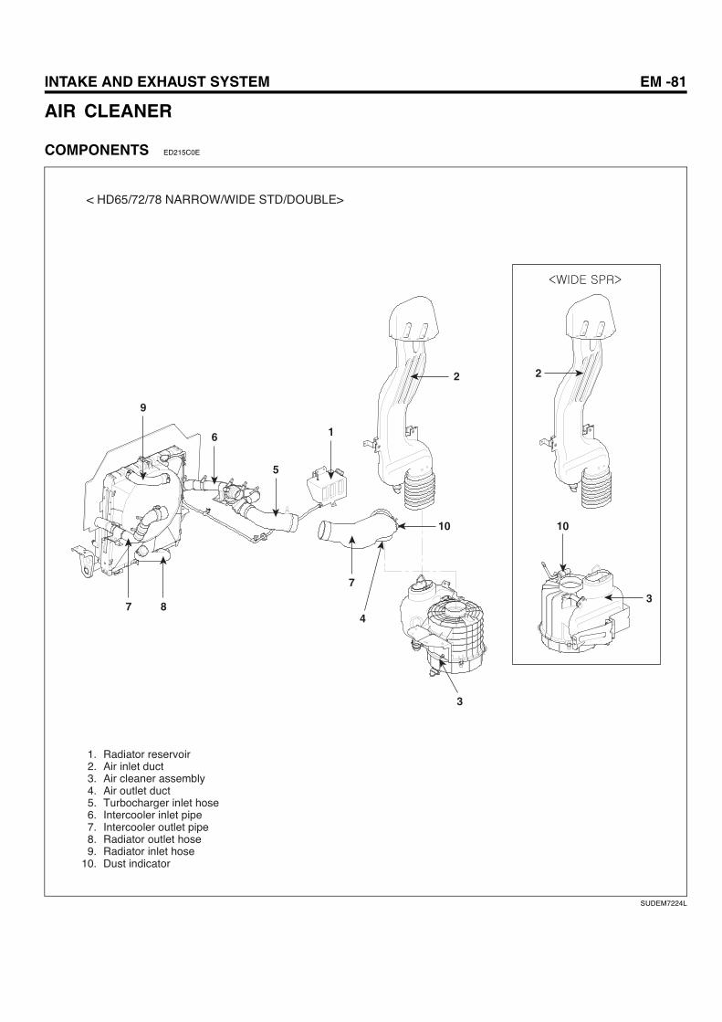
INTAKE AND EXHAUST SYSTEM EM -81
AIR CLEANER
COMPONENTS ED215C0E
< HD65/72/78 NARROW/WIDE STD/DOUBLE>
10
7
4
22
3
3
10
6
7 8
5
1
9
1. Radiator reservoir2. Air inlet duct3. Air cleaner assembly4. Air outlet duct5. Turbocharger inlet hose6. Intercooler inlet pipe7. Intercooler outlet pipe8. Radiator outlet hose9. Radiator inlet hose
10. Dust indicator
SUDEM7224L

EM -82 ENGINE MECHANICAL SYSTEM
7
10
9
6
5
8
6
4
3
2
1
County
1. Inlet duct2. Clamp3. Air cleaner assembly4. Air outlet pipe5. Dust indicator6. Intercooler in/out pipe7. Radiator reservoir8. Radiator upper hose9. Exhaust manifold assembly
10. Turbocharger assembly
SUDEM7225L

INTAKE AND EXHAUST SYSTEM EM -83
HD65/72/78
7
6
8.8~13.7(0.9~1.4, 6.5~10.2)
8.8~13.7(0.9~1.4, 6.5~10.2)
8
4
2
1
5
3
1. Exhaust pipe2. Muffler assembly3. Tail pipe4. Suspend assembly5. Bracket6. Exhaust brake unit7. Turbocharger assembly8. Battery carrier
Tightening Torque : Nm (kgf.m, Ib-ft)
SUDEM7226L

EM -84 ENGINE MECHANICAL SYSTEM
County
3
4
65
2
1
1. Exhaust pipe2. Exhaust brake unit3. Muffler assembly4. Tail pipe5. Turbocharger assembly6. Exhaust manifold assembly
SUDEM7227L
INTAKE AND EXHAUST SYSTEM EM -85
INSPECTION EB12EA6F
AIR CLEANER
1. When dust indicator turns red, which tells the filterreplacement interval, replace the element.
CAUTIONReplace the element at least once per 2 years.Do not reuse it after cleaning.
2. Replacement of air cleaner filter.a. Loosen the clamp of the air cleaner assembly.b. Remove the lower cap of air cleaner assembly.c. Loosen butterfly nut of element.d. Remove the element.e. Clean the inside of air cleaner thoroughly.f. Replace the air cleaner element with new one.
CAUTION
When replacing the element, exercise caution thatair-cleaner should not contain any dust or foreignmaterial.
g. Tighten the butterfly nut of element.h. Check to see if the packing at the air-cleaner as-
sembly is correctly installed. If correctly installed,install the lower cap.
i. Fix the lower cap by tightening the clamp.j. Press the dust indicator reset button so that the
red color disappears.
CAUTIONGenuine parts of the air-cleaner must be used. Ifthe vehicle is driven with the air-cleaner removed,it may be the cause of early engine damage.
EXHAUST MUFFLER
1. Check the exhaust system for any unusual noise.
2. Check the exhaust muffler for connection and corro-sion.
3. Check the exhaust muffler gasket for any damage.

EM -86 ENGINE MECHANICAL SYSTEM
LUBRICATION SYSTEM
DESCRIPTION E3DF9F3D
FLOW CHART OF LUBRICATION SYSTEM
Engine is lubricated by a gear-type oil pump that forcesengine oil through the oil cooler and oil filter into the enginefor lubrication of various engine parts.
Main oil gallery
Bypass valve
Oil filterOil pressure switch
Idler gear bush
Crankshaft main bearing
Camshaft bush
Oil cooler OrificeTiming gear
Connecting rod bearing
Rocker bush
Regulator valve
Oil pump
Relief valve
Connecting bush Push rod
Turbo charger
tappet vacuum pump
oil jet
piston
oil strainer
oil pan
SUDEM7228L
OIL PUMP
The oil pump, of a gear type, is driven by the crankshaftrotation engaged with oil pump gear. And the relief valveis installed to the oil pump so that it prevents the excessivepressure by bypassing the engine oil to oil pan when theoil pressure exceeds the specification.
A
BC
Relief valve
Drive gear Oil pump gear
Oil pump cover
Driven gear
Oil pump case
A: from oil strainerB: to oil coolerC: to oil pan
SUDEM7229L
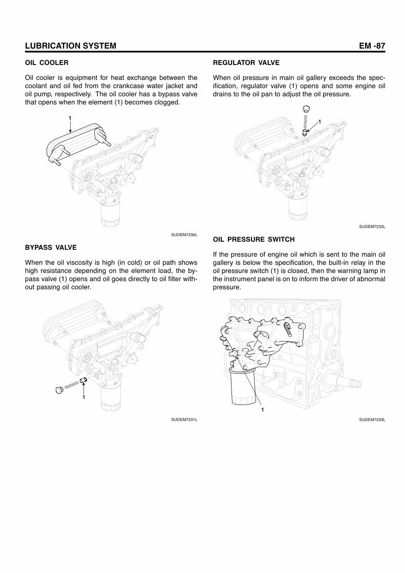
LUBRICATION SYSTEM EM -87
OIL COOLER
Oil cooler is equipment for heat exchange between thecoolant and oil fed from the crankcase water jacket andoil pump, respectively. The oil cooler has a bypass valvethat opens when the element (1) becomes clogged.
1
SUDEM7230L
BYPASS VALVE
When the oil viscosity is high (in cold) or oil path showshigh resistance depending on the element load, the by-pass valve (1) opens and oil goes directly to oil filter with-out passing oil cooler.
1
SUDEM7231L
REGULATOR VALVE
When oil pressure in main oil gallery exceeds the spec-ification, regulator valve (1) opens and some engine oildrains to the oil pan to adjust the oil pressure.
1
SUDEM7232L
OIL PRESSURE SWITCH
If the pressure of engine oil which is sent to the main oilgallery is below the specification, the built-in relay in theoil pressure switch (1) is closed, then the warning lamp inthe instrument panel is on to inform the driver of abnormalpressure.
1
SUDEM7233L
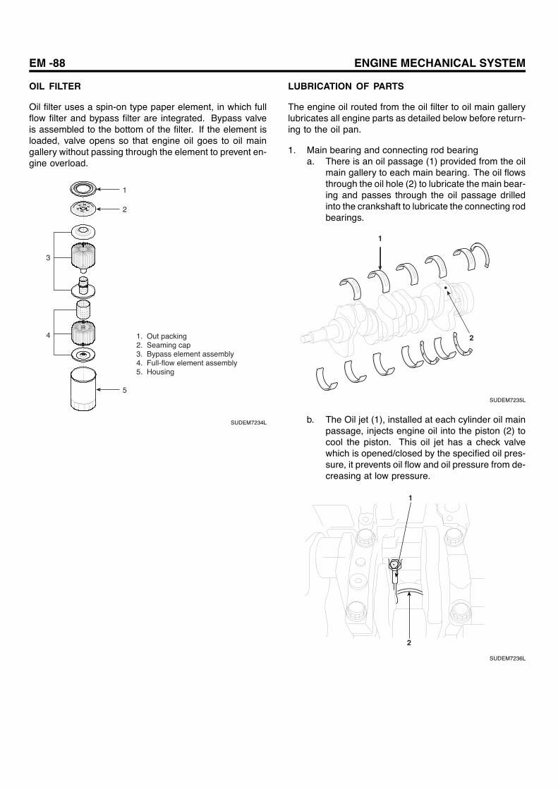
EM -88 ENGINE MECHANICAL SYSTEM
OIL FILTER
Oil filter uses a spin-on type paper element, in which fullflow filter and bypass filter are integrated. Bypass valveis assembled to the bottom of the filter. If the element isloaded, valve opens so that engine oil goes to oil maingallery without passing through the element to prevent en-gine overload.
1. Out packing2. Seaming cap3. Bypass element assembly4. Full-flow element assembly5. Housing
1
2
3
4
5
SUDEM7234L
LUBRICATION OF PARTS
The engine oil routed from the oil filter to oil main gallerylubricates all engine parts as detailed below before return-ing to the oil pan.
1. Main bearing and connecting rod bearinga. There is an oil passage (1) provided from the oil
main gallery to each main bearing. The oil flowsthrough the oil hole (2) to lubricate the main bear-ing and passes through the oil passage drilledinto the crankshaft to lubricate the connecting rodbearings.
1
2
SUDEM7235L
b. The Oil jet (1), installed at each cylinder oil mainpassage, injects engine oil into the piston (2) tocool the piston. This oil jet has a check valvewhich is opened/closed by the specified oil pres-sure, it prevents oil flow and oil pressure from de-creasing at low pressure.
1
2
SUDEM7236L
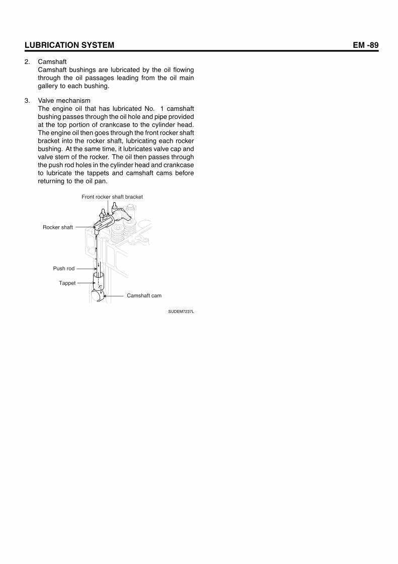
LUBRICATION SYSTEM EM -89
2. CamshaftCamshaft bushings are lubricated by the oil flowingthrough the oil passages leading from the oil maingallery to each bushing.
3. Valve mechanismThe engine oil that has lubricated No. 1 camshaftbushing passes through the oil hole and pipe providedat the top portion of crankcase to the cylinder head.The engine oil then goes through the front rocker shaftbracket into the rocker shaft, lubricating each rockerbushing. At the same time, it lubricates valve cap andvalve stem of the rocker. The oil then passes throughthe push rod holes in the cylinder head and crankcaseto lubricate the tappets and camshaft cams beforereturning to the oil pan.
Front rocker shaft bracket
Rocker shaft
Push rod
Tappet
Camshaft cam
SUDEM7237L

EM -90 ENGINE MECHANICAL SYSTEM
SPECIFICATION EADD3E2D
OIL COOLER
Item Specification
Bypass valve open 3.5~4.5kg/cm²(361~419kpa)
Regulator oil pump valve open 5~7kg/cm²(490~686kpa)
OIL PUMP
Item Specification
Module 2.0
Pressure angle 20
N0. of gear teeth 36
distortion angle 19.5
Head gear
Backlash (mm) 0.049~0.151
Pump rotation (rpm) 550~3100
Oil Temperature ( C) -25~130
Oil in use SAE 10W~30W
Injection pressure MPa (kgf/cm²) 0.4(4)
Injection amount (ℓ /min) 25
Relief valve operating pressure MPa (kgf/cm²) 1.1±0.1 (11±1)
OIL FILTER
Item Specification
Filtration capacity Full-flow : above 1700cm³By-pass : above 2400cm³
Pressure loss Below 0.5kgf/cm²
Bypass opening pressure MPa (kgf/cm²) 98±20 (1.0±0.2)
Bypass pressure loss MPa (kgf/cm²) 157±20 (1.6±0.2)
LUBRICANT
Item Types Oil grade Oil viscosity (temperatureapplied) Oil capacity
Engine oil API classification gradeCF—4 or moreSAE 10W-30
Grade CF-4or more
1) 0~40 C : SAE 302) above -10 C: SAE 20W-403) above -15 C: SAE 15W-404) -20~40 C : SAE 10W-305) below 10 C: SAE 15W-30
Oil pan : 8ℓTotal capacity : 9ℓ
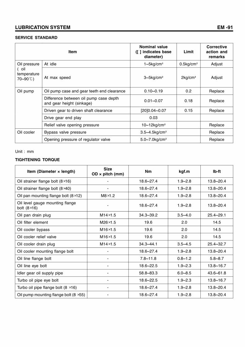
LUBRICATION SYSTEM EM -91
SERVICE STANDARD
ItemNominal value
([ ] indicates basediameter)
LimitCorrectiveaction andremarks
At idle 1~5kg/cm² 0.5kg/cm² AdjustOil pressure( oiltemperature70~90℃) At max speed 3~5kg/cm² 2kg/cm² Adjust
Oil pump case and gear teeth end clearance 0.10~0.19 0.2 Replace
Difference between oil pump case depthand gear height (sinkage)
0.01~0.07 0.18 Replace
Driven gear to driven shaft clearance [20]0.04~0.07 0.15 Replace
Drive gear end play 0.03
Oil pump
Relief valve opening pressure 10~12kg/cm² Replace
Bypass valve pressure 3.5~4.5kg/cm² ReplaceOil cooler
Opening pressure of regulator valve 5.0~7.0kg/cm² Replace
Unit : mm
TIGHTENING TORQUE
Item (Diameter × length) SizeOD × pitch (mm) Nm kgf.m Ib-ft
Oil strainer flange bolt (8×16) - 18.6~27.4 1.9~2.8 13.8~20.4
Oil strainer flange bolt (8×40) - 18.6~27.4 1.9~2.8 13.8~20.4
Oil pan mounting flange bolt (8×12) M8×1.2 18.6~27.4 1.9~2.8 13.8~20.4
Oil level gauge mounting flangebolt (8×16)
- 18.6~27.4 1.9~2.8 13.8~20.4
Oil pan drain plug M14×1.5 34.3~39.2 3.5~4.0 25.4~29.1
Oil filter element M26×1.5 19.6 2.0 14.5
Oil cooler bypass M16×1.5 19.6 2.0 14.5
Oil cooler relief valve M16×1.5 19.6 2.0 14.5
Oil cooler drain plug M14×1.5 34.3~44.1 3.5~4.5 25.4~32.7
Oil cooler mounting flange bolt - 18.6~27.4 1.9~2.8 13.8~20.4
Oil line flange bolt - 7.8~11.8 0.8~1.2 5.8~8.7
Oil line eye bolt - 18.6~22.5 1.9~2.3 13.8~16.7
Idler gear oil supply pipe - 58.8~83.3 6.0~8.5 43.6~61.8
Turbo oil pipe eye bolt - 18.6~22.5 1.9~2.3 13.8~16.7
Turbo oil pipe flange bolt (8 ×16) - 18.6~27.4 1.9~2.8 13.8~20.4
Oil pump mounting flange bolt (8×55) - 18.6~27.4 1.9~2.8 13.8~20.4
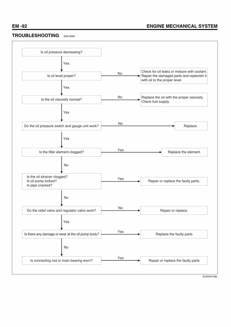
EM -92 ENGINE MECHANICAL SYSTEM
TROUBLESHOOTING EBA1856F
Is oil pressure decreasing?
Is oil level proper?
Is the oil viscosity normal?
Do the oil pressure switch and gauge unit work?
Is the filter element clogged?
Is the oil strainer clogged?Is oil pump locked?Is pipe cracked?
Do the relief valve and regulator valve work?
Is there any damage or wear at the oil pump body?
Is connecting rod or main bearing worn? Repair or replace the faulty parts
Replace the faulty parts
Repair or replace.
Repair or replace the faulty parts.
Replace the element.
Replace.
Replace the oil with the proper viscosity.Check fuel supply.
Check for oil leaks or mixture with coolant. Repair the damaged parts and replenish it with oil to the proper level.
No
No
No
No
No
No
No
Yes
Yes
Yes
Yes
Yes
Yes
Yes
Yes
Yes
SUDEM7238L

LUBRICATION SYSTEM EM -93
No
No
No
No
Yes
Yes
Yes
Excessive oil consumption
Check the following items for a leakage Oil filter Oil cooler Oil pan Oil pipe Oil cover
Repair the leaking parts.
Repair or replace the faulty parts.
Is oil leaking from the oil seals of front and rear crankshaft?
Is any damage in cooling system?Repair the damage of oil cooler and water jacket etc.
Check the abrasion of the engine bearing which causes a leakage of oil.
Repair or replace.
SUDEM7239L
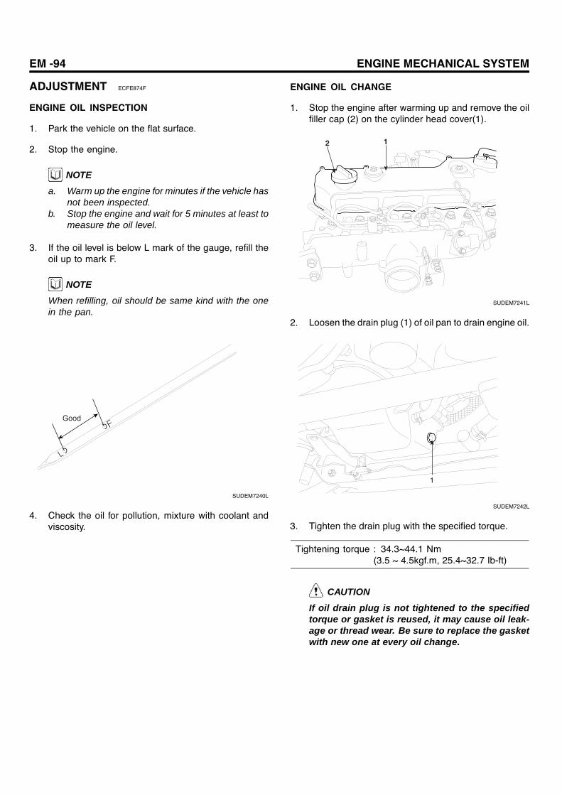
EM -94 ENGINE MECHANICAL SYSTEM
ADJUSTMENT ECFE874F
ENGINE OIL INSPECTION
1. Park the vehicle on the flat surface.
2. Stop the engine.
NOTEa. Warm up the engine for minutes if the vehicle has
not been inspected.b. Stop the engine and wait for 5 minutes at least to
measure the oil level.
3. If the oil level is below L mark of the gauge, refill theoil up to mark F.
NOTEWhen refilling, oil should be same kind with the onein the pan.
Good
SUDEM7240L
4. Check the oil for pollution, mixture with coolant andviscosity.
ENGINE OIL CHANGE
1. Stop the engine after warming up and remove the oilfiller cap (2) on the cylinder head cover(1).
2 1
SUDEM7241L
2. Loosen the drain plug (1) of oil pan to drain engine oil.
1
SUDEM7242L
3. Tighten the drain plug with the specified torque.
Tightening torque : 34.3~44.1 Nm(3.5 ~ 4.5kgf.m, 25.4~32.7 Ib-ft)
CAUTION
If oil drain plug is not tightened to the specifiedtorque or gasket is reused, it may cause oil leak-age or thread wear. Be sure to replace the gasketwith new one at every oil change.
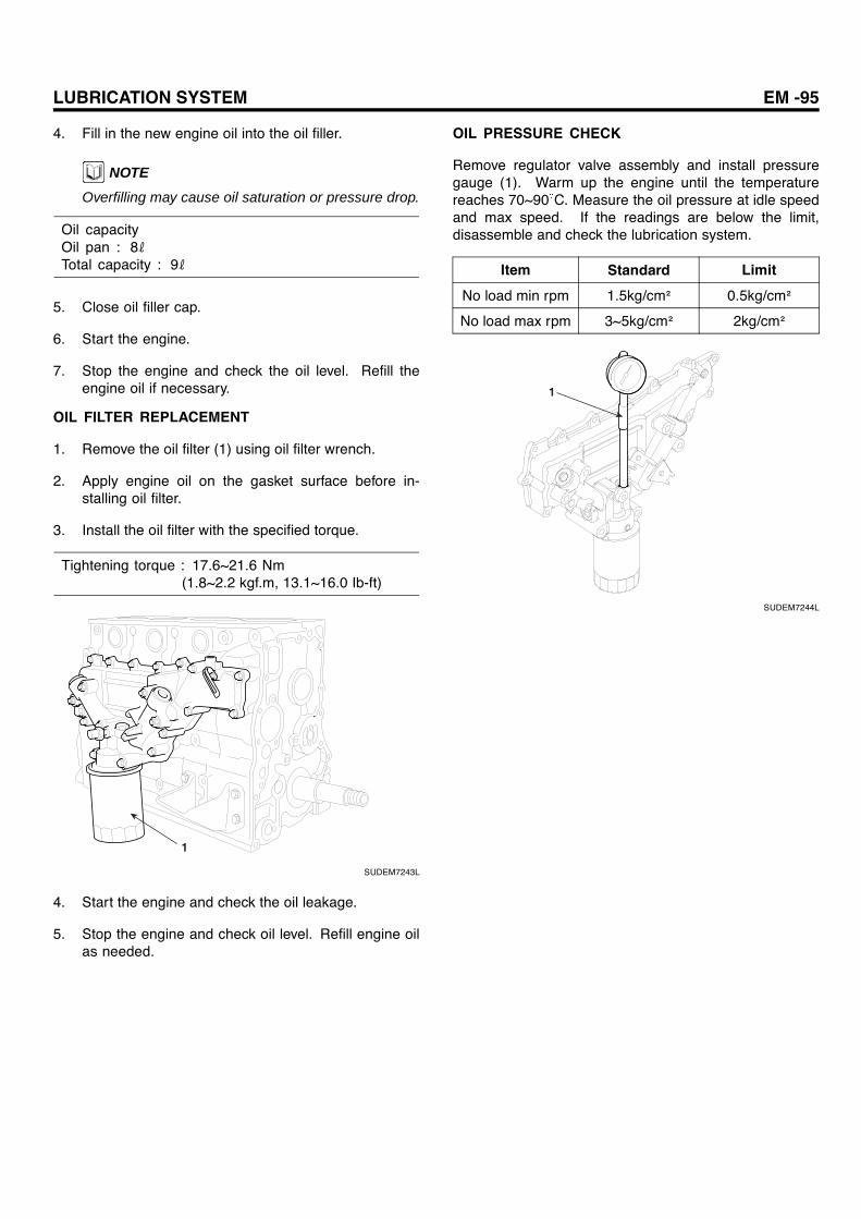
LUBRICATION SYSTEM EM -95
4. Fill in the new engine oil into the oil filler.
NOTEOverfilling may cause oil saturation or pressure drop.
Oil capacityOil pan : 8ℓTotal capacity : 9ℓ
5. Close oil filler cap.
6. Start the engine.
7. Stop the engine and check the oil level. Refill theengine oil if necessary.
OIL FILTER REPLACEMENT
1. Remove the oil filter (1) using oil filter wrench.
2. Apply engine oil on the gasket surface before in-stalling oil filter.
3. Install the oil filter with the specified torque.
Tightening torque : 17.6~21.6 Nm(1.8~2.2 kgf.m, 13.1~16.0 Ib-ft)
1
SUDEM7243L
4. Start the engine and check the oil leakage.
5. Stop the engine and check oil level. Refill engine oilas needed.
OIL PRESSURE CHECK
Remove regulator valve assembly and install pressuregauge (1). Warm up the engine until the temperaturereaches 70~90 C. Measure the oil pressure at idle speedand max speed. If the readings are below the limit,disassemble and check the lubrication system.
Item Standard Limit
No load min rpm 1.5kg/cm² 0.5kg/cm²
No load max rpm 3~5kg/cm² 2kg/cm²
1
SUDEM7244L

EM -96 ENGINE MECHANICAL SYSTEM
OIL PUMP
COMPONENTS E68A3564
1
2
6
3
18.6~27.4(1.9 ~ 2.8, 13.8~20.4)
34.3~39.2(3.5 ~ 4.0, 25.4~29.1)
18.6~27.4(1.9 ~ 2.8, 13.8~20.4)
18.6~27.4(1.9 ~ 2.8, 13.8~20.4)
4
5
4.1
1. Crankcase2. Oil strainer3. O-ring4. Oil pan drain plug5. Oil pan6. Stiffener
Tightening Torque : Nm (kgf.m, Ib-ft)
SUDEM7245L
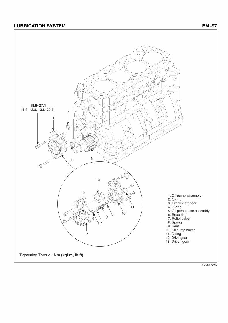
LUBRICATION SYSTEM EM -97
2
1
18.6~27.4(1.9 ~ 2.8, 13.8~20.4)
13
5
6 78
9 10
11
12
4 3
1. Oil pump assembly2. O-ring3. Crankshaft gear4. O-ring5. Oil pump case assembly6. Snap ring7. Relief valve8. Spring9. Seat
10. Oil pump cover11. O-ring12. Drive gear13. Driven gear
Tightening Torque : Nm (kgf.m, Ib-ft)
SUDEM7246L
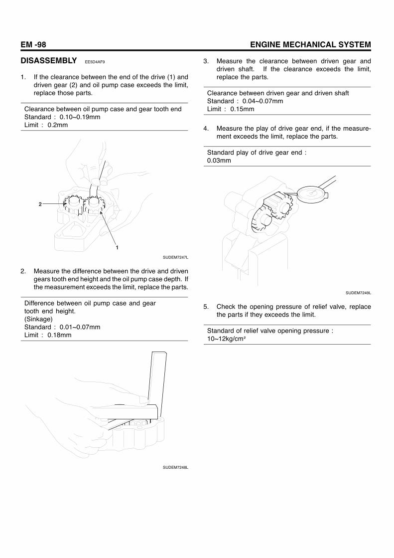
EM -98 ENGINE MECHANICAL SYSTEM
DISASSEMBLY EE5D4AF9
1. If the clearance between the end of the drive (1) anddriven gear (2) and oil pump case exceeds the limit,replace those parts.
Clearance between oil pump case and gear tooth endStandard : 0.10~0.19mmLimit : 0.2mm
2
1
SUDEM7247L
2. Measure the difference between the drive and drivengears tooth end height and the oil pump case depth. Ifthe measurement exceeds the limit, replace the parts.
Difference between oil pump case and geartooth end height.(Sinkage)Standard : 0.01~0.07mmLimit : 0.18mm
SUDEM7248L
3. Measure the clearance between driven gear anddriven shaft. If the clearance exceeds the limit,replace the parts.
Clearance between driven gear and driven shaftStandard : 0.04~0.07mmLimit : 0.15mm
4. Measure the play of drive gear end, if the measure-ment exceeds the limit, replace the parts.
Standard play of drive gear end :0.03mm
SUDEM7249L
5. Check the opening pressure of relief valve, replacethe parts if they exceeds the limit.
Standard of relief valve opening pressure :10~12kg/cm²

LUBRICATION SYSTEM EM -99
OIL COOLER
COMPONENTS E221CA2C
1. Oil cooler element 2. Oil cooler body assembly 3. Plug 4. Spring 5. Bypass valve 6. Plug 7. Spring 8. Regulator valve 9. Out packing10. Seaming cap assembly11. Bypass element assembly12. Full flow assembly13. Housing
1
19.6 (2.0, 14.5)
19.6 (2.0, 14.5)
19.6 (2.0, 14.5)
11.8 (1.2, 8.7)
34.3~39.2(3.5 ~ 4.0, 25.4~29.1)
6
78
9
10
11
12
13
2
34
5
Tightening Torque : Nm (kgf.m, Ib-ft)
SUDEM7250L
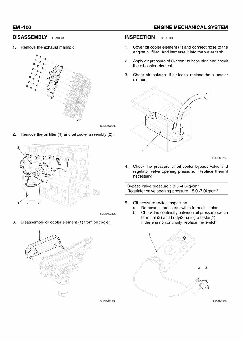
EM -100 ENGINE MECHANICAL SYSTEM
DISASSEMBLY EEA50548
1. Remove the exhaust manifold.
SUDEM7251L
2. Remove the oil filter (1) and oil cooler assembly (2).
2
1
SUDEM7252L
3. Disassemble oil cooler element (1) from oil cooler.
1
SUDEM7253L
INSPECTION EC9C5BDC
1. Cover oil cooler element (1) and connect hose to theengine oil filler. And immerse it into the water tank.
2. Apply air pressure of 3kg/cm² to hose side and checkthe oil cooler element.
3. Check air leakage. If air leaks, replace the oil coolerelement.
1
SUDEM7254L
4. Check the pressure of oil cooler bypass valve andregulator valve opening pressure. Replace them ifnecessary.
Bypass valve pressure : 3.5~4.5kg/cm²Regulator valve opening pressure : 5.0~7.0kg/cm²
5. Oil pressure switch inspectiona. Remove oil pressure switch from oil cooler.b. Check the continuity between oil pressure switch
terminal (2) and body(3) using a tester(1).If there is no continuity, replace the switch.
1
2 3
SUDEM7255L

LUBRICATION SYSTEM EM -101
c. Insert the slim rod (1) into oil hole of oil pressureswitch and check the continuity.If there is continuity, replace the parts because itis faulty.
1
SUDEM7256L
CLEANING
1. Check the oil path and bypass valve of the oil coolerelement for carbon deposits and sludge formation. Ifcontaminated, wash it in cleaning oil.
2. If much scale is evident on the element and cover,clean it.
REASSEMBLY EC45CF49
Assembly is made in the reverse order of disassembly.When installing oil cooler, align oil cooler with the oil pumpinstallation surface.
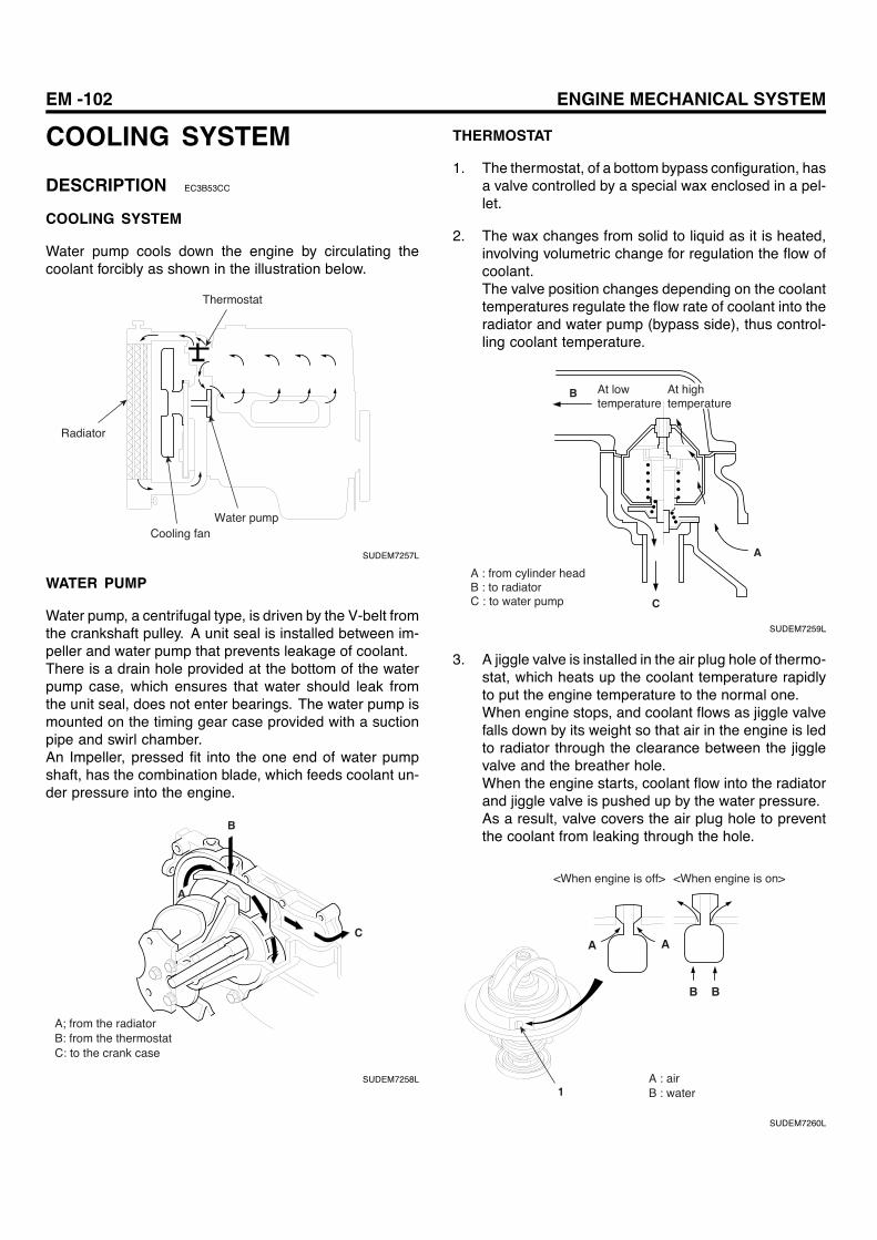
EM -102 ENGINE MECHANICAL SYSTEM
COOLING SYSTEM
DESCRIPTION EC3B53CC
COOLING SYSTEM
Water pump cools down the engine by circulating thecoolant forcibly as shown in the illustration below.
Thermostat
Radiator
Cooling fanWater pump
SUDEM7257L
WATER PUMP
Water pump, a centrifugal type, is driven by the V-belt fromthe crankshaft pulley. A unit seal is installed between im-peller and water pump that prevents leakage of coolant.There is a drain hole provided at the bottom of the waterpump case, which ensures that water should leak fromthe unit seal, does not enter bearings. The water pump ismounted on the timing gear case provided with a suctionpipe and swirl chamber.An Impeller, pressed fit into the one end of water pumpshaft, has the combination blade, which feeds coolant un-der pressure into the engine.
C
A
B
A; from the radiatorB: from the thermostatC: to the crank case
SUDEM7258L
THERMOSTAT
1. The thermostat, of a bottom bypass configuration, hasa valve controlled by a special wax enclosed in a pel-let.
2. The wax changes from solid to liquid as it is heated,involving volumetric change for regulation the flow ofcoolant.The valve position changes depending on the coolanttemperatures regulate the flow rate of coolant into theradiator and water pump (bypass side), thus control-ling coolant temperature.
C
A
B At high temperature
A : from cylinder headB : to radiatorC : to water pump
At low temperature
SUDEM7259L
3. A jiggle valve is installed in the air plug hole of thermo-stat, which heats up the coolant temperature rapidlyto put the engine temperature to the normal one.When engine stops, and coolant flows as jiggle valvefalls down by its weight so that air in the engine is ledto radiator through the clearance between the jigglevalve and the breather hole.When the engine starts, coolant flow into the radiatorand jiggle valve is pushed up by the water pressure.As a result, valve covers the air plug hole to preventthe coolant from leaking through the hole.
1
A A
B B
<When engine is off> <When engine is on>
A : airB : water
SUDEM7260L

COOLING SYSTEM EM -103
RADIATOR
The radiator, which consists of tube-and-corrugated-fintype core, not only cools the engine coolant but alsoseparates vapor from liquid water and regulates pressurein the cooling system.
Radiator cap
Radiator
SUDEM7261L
RADIATOR CAP
Radiator cap regulates the pressure in the cooling system.When the pressure exceeds the predetermined level, thepressure valve compresses the pressure spring to releasethe excessive pressure to the air.As the coolant temperature drops and forms a vacuumin the radiator, the vent valve opens to admit air into theradiator, thus preventing the radiator from being deformedby the vacuum.
When pressure forms
When vacuum forms
A
B
A : to the reservoir tankB : from the reservoir tank
SUDEM7262L
AUTO COLLING FAN
Autocool fan coupling is the device to control the fan speedaccording to the engine coolant temperature. The bimetaldetects the air temperature running through the radiatorand varies the fluid coupling flows to control the fan speed.
1. When the air temperature in the radiator is high,bimetal is deformed and opens the reservoir valve.
2. Since the fluid (silicon oil) keeps flowing, viscositybetween the coupling case and rotor increases, andthe fan mounted to the case has the similar speed ofshaft. Viscosity varies with the fluid amount (siliconoil).
3. When the air temperature falls, the bimetal is operatedto close the valve and the fluid returns to the reservoir.It results in a quick speed decrease by sliding betweenthe coupling case and rotor.
Working areaSilicon oil storage area
Rotor
Bimetal
Coupling shaft
Coupling case
SUDEM7263L
OPERATION OF AUTOCOOL FAN COUPLING
<At high temperature> Pump protrusion
Pump hole
Fluid (silicon oil)
Valve
Separator plate
Pump chamber
<At low temperature>Pump protrusion
Pump hole
Pump chamber
SUDEM7264L
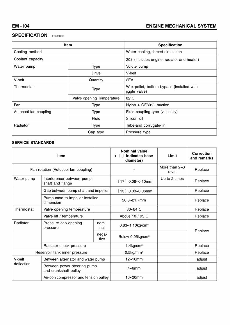
EM -104 ENGINE MECHANICAL SYSTEM
SPECIFICATION EC630CCE
Item Specification
Cooling method Water cooling, forced circulation
Coolant capacity 20ℓ (includes engine, radiator and heater)
Type Volute pumpWater pump
Drive V-belt
V-belt Quantity 2EA
TypeWax-pellet, bottom bypass (installed withjiggle valve)
Thermostat
Valve opening Temperature 82 C
Fan Type Nylon + GF30%, suction
Type Fluid coupling type (viscosity)Autocool fan coupling
Fluid Silicon oil
Type Tube-and corrugate-finRadiator
Cap type Pressure type
SERVICE STANDARDS
ItemNominal value
(〔 〕indicates basediameter)
Limit Correctionand remarks
Fan rotation (Autocool fan coupling) - More than 2~3revs.
Replace
Interference between pumpshaft and flange 〔17〕0.08~0.10mm
Up to 2 timesReplace
Gap between pump shaft and impeller 〔13〕0.03~0.06mm Replace
Water pump
Pump case to impeller installeddimension
20.8~21.7mm Replace
Valve opening temperature 80~84 C ReplaceThermostat
Valve lift / temperature Above 10 / 95 C Replace
nomi-nal
0.83~1.10kg/cm²Pressure cap openingpressure
nega-tive Below 0.05kg/cm²
Replace
Radiator
Radiator check pressure 1.4kg/cm² Replace
Reservoir tank inner pressure 0.5kg/mm² Replace
Between alternator and water pump 12~16mm adjust
Between power steering pumpand crankshaft pulley
4~6mm adjust
V-beltdeflection
Air-con compressor and tension pulley 16~20mm adjust
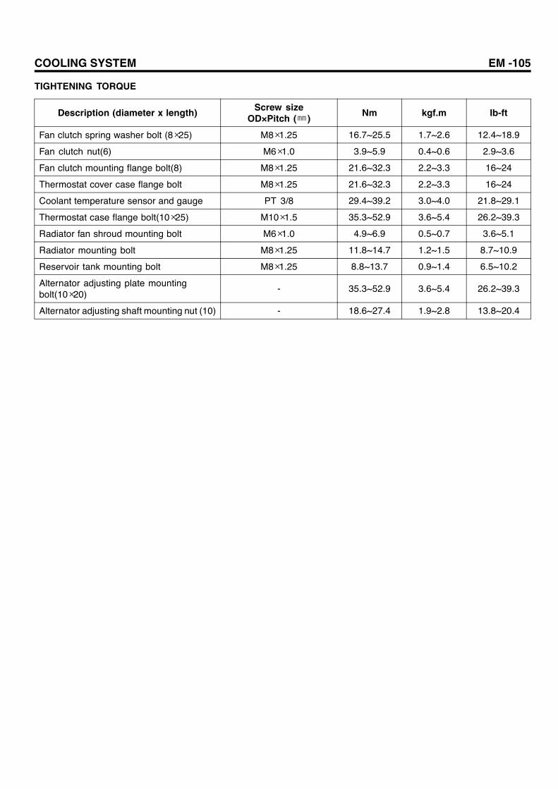
COOLING SYSTEM EM -105
TIGHTENING TORQUE
Description (diameter x length) Screw sizeOD×Pitch (㎜) Nm kgf.m Ib-ft
Fan clutch spring washer bolt (8×25) M8×1.25 16.7~25.5 1.7~2.6 12.4~18.9
Fan clutch nut(6) M6×1.0 3.9~5.9 0.4~0.6 2.9~3.6
Fan clutch mounting flange bolt(8) M8×1.25 21.6~32.3 2.2~3.3 16~24
Thermostat cover case flange bolt M8×1.25 21.6~32.3 2.2~3.3 16~24
Coolant temperature sensor and gauge PT 3/8 29.4~39.2 3.0~4.0 21.8~29.1
Thermostat case flange bolt(10×25) M10×1.5 35.3~52.9 3.6~5.4 26.2~39.3
Radiator fan shroud mounting bolt M6×1.0 4.9~6.9 0.5~0.7 3.6~5.1
Radiator mounting bolt M8×1.25 11.8~14.7 1.2~1.5 8.7~10.9
Reservoir tank mounting bolt M8×1.25 8.8~13.7 0.9~1.4 6.5~10.2
Alternator adjusting plate mountingbolt(10×20)
- 35.3~52.9 3.6~5.4 26.2~39.3
Alternator adjusting shaft mounting nut (10) - 18.6~27.4 1.9~2.8 13.8~20.4

EM -106 ENGINE MECHANICAL SYSTEM
TROUBLE SHOOTING E37CE1A7
Overheat
Is the tension of V-belt normal?
Is coolant level proper?
Is there any clogged radiator fan?
Is coolant polluted or rusted?
Is thermostat operating?
Does water pump work properly?
Is there any leak in the auto cooling fan coupling?
Check the all possible causes of overheating.
Adjust the tension of the belt and after checking the belt, replace it if necessary.
Add the coolant, and if there is a leak, check the cooling system.
Clean the radiator core and adjust the deformation of core if necessary.
Clean the cooling system
Replace the thermostat
Replace the water pump
Replace the fan coupling
Yes
Yes
Yes
No
No
Yes
Yes
No
No
No
Yes
Yes
No
No
Yes
SUDEM7265L

COOLING SYSTEM EM -107
There is heavy loss of coolant.
Is the radiator hose leaking?
Is the radiator core leaking?
Is the water pump leaking?
Is the radiator pressure pump leaking?
Replace the O-ring
Replace the pressure valve.
Is the oil cooler leaking?
Check the possible leaking spots of the engine.
Does the hose clamp tighten properly?
Any gas in the coolant leaked from cylinder head gasket?
Defective or damaged O-ring?
Are bolts tightened properly?
Repair or replace the radiator.
Replace the hose.
Tighten the clamp.
Cracked or damaged hose?
Tighten the bolts.
Is the pressure range correct in the pressure valve?
Is gasket in good condition?
No
No
No
No
No
Yes
Yes
No
Yes
Yes
Yes
No
Yes
Yes
Yes
No
No
YesReplace.
Replace the cylinder head gasket.
SUDEM7266L

EM -108 ENGINE MECHANICAL SYSTEM
WATER PUMP
COMPONENTS E27DE054
21.6~32.3(2.2~3.3, 16~24)
2
3
4
5
21.6~32.3 (2.2~3.3, 16~24)35.3~52.9 (3.6~5.4, 26.2~39.3)
6
7
8
9
16.7~25.5(1.7~2.6, 12.4~18.9)
3.9~5.9(0.4~0.6, 2.9~4.4)
1
1. Cooling fan 2. Autocool fan coupling 3. Coupling plate 4. Water pump pulley 5. V-belt 6. Water pump assembly
7. O-ring 8. Crankshaft damper pulley9. Thermostat housing
Tightening Torque : Nm (kgf.m, Ib-ft)
SUDEM7267L

COOLING SYSTEM EM -109
REMOVAL E9DD1BEE
1. Remove the coolant drain plug and drain the coolant.
2. Loosen the alternator (1) tension adjusting screw (2)and remove V-belt (3).
2
3
1
SUDEM7268L
3. Remove the cooling fan (1) and autocool fan coupling(2).
2
1
SUDEM7269L
4. Remove water pump pulley(1) and water pump as-sembly(2).
1
2
SUDEM7270L
5. Disassemble the coolant temperature sensor connec-tor and remove the thermostat housing(1) from thecylinder head.a. Remove the thermostat cover.b. Remove the thermostat.c. Disassemble the bypass pipe from the thermo-
stat case.d. Remove the coolant temperature sensor.
1
SUDEM7271L

EM -110 ENGINE MECHANICAL SYSTEM
INSPECTION EE28BF77
WATER PUMP
1. Inspect the crack, damage, and wear of the parts, andreplace the water pump, if necessary.
2. Inspect the bearing to see any damage, unusualnoise, and poor revolution, and replace it, if neces-sary.
3. Check the leakage of the seal unit and replace thewater pump, if necessary.
THERMOSTAT
1. Heat the water to see if the thermostat valve operatesproperly.
2. Measure the temperature when the valve starts open-ing and is fully open.
Item Specification
Valve opening temperature 80~84 C
Valve lift / temperature more than 10 / 95 C
SUDEM7272L
V-BELT TENSION CHECK
Adjust the belt tension to obtain the specified belt deflec-tion when the center of each belt is pressed hard with aforce of 10 kgf.
Deflection between the alternator(1) and waterpump(2) : 12~16mm
CAUTIONa. Since a slack belt may cause overheating or
undercharge, adjust the tension to the speci-fication.
b. An excessively tight belt may result in possi-ble damages of the belt or bearing.
c. All of two V-belts should be replaced as acomplete set.
1
2
SUDEM7273L
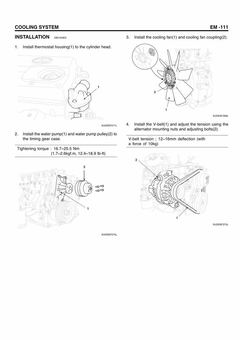
COOLING SYSTEM EM -111
INSTALLATION EBC443E9
1. Install thermostat housing(1) to the cylinder head.
1
SUDEM7271L
2. Install the water pump(1) and water pump pulley(2) tothe timing gear case.
Tightening torque : 16.7~25.5 Nm(1.7~2.6kgf.m, 12.4~18.9 Ib-ft)
2
1
SUDEM7274L
3. Install the cooling fan(1) and cooling fan coupling(2).
2
1
SUDEM7269L
4. Install the V-belt(1) and adjust the tension using thealternator mounting nuts and adjusting bolts(2).
V-belt tension ; 12~16mm deflection (witha force of 10kg)
2
1
SUDEM7275L

EM -112 ENGINE MECHANICAL SYSTEM
RADIATOR
COMPONENTS EFAA2107
4
5
4.9~6.9(0.5~0.7, 3.6~5.1)
3
2
1
7
11.8~14.7 (1.2~1.5, 8.7~10.9)
11.8~14.7 (1.2~1.5, 8.7~10.9)
6
8
1. Rod 2. Plate 3. Intercooler 4. Radiator cap 5. Radiator hose upper 6. Radiator hose lower 7. Radiator 8. Shroud
Tightening Torque : Nm (kgf.m, Ib-ft)
SUDEM7276L
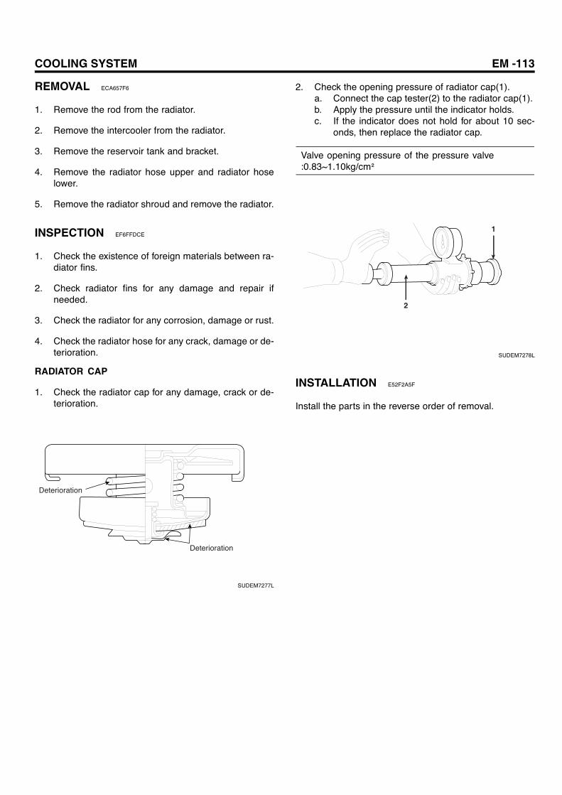
COOLING SYSTEM EM -113
REMOVAL ECA657F6
1. Remove the rod from the radiator.
2. Remove the intercooler from the radiator.
3. Remove the reservoir tank and bracket.
4. Remove the radiator hose upper and radiator hoselower.
5. Remove the radiator shroud and remove the radiator.
INSPECTION EF6FFDCE
1. Check the existence of foreign materials between ra-diator fins.
2. Check radiator fins for any damage and repair ifneeded.
3. Check the radiator for any corrosion, damage or rust.
4. Check the radiator hose for any crack, damage or de-terioration.
RADIATOR CAP
1. Check the radiator cap for any damage, crack or de-terioration.
Deterioration
Deterioration
SUDEM7277L
2. Check the opening pressure of radiator cap(1).a. Connect the cap tester(2) to the radiator cap(1).b. Apply the pressure until the indicator holds.c. If the indicator does not hold for about 10 sec-
onds, then replace the radiator cap.
Valve opening pressure of the pressure valve:0.83~1.10kg/cm²
1
2
SUDEM7278L
INSTALLATION E52F2A5F
Install the parts in the reverse order of removal.