© Copyright 3Dlabs, 1999 - Page 1 - PROPRIETARY & CONFIDENTIAL Challenges & Opportunities for 3D...
34
© Copyright 3Dlabs, 1999 - Page 1 - PROPRIETARY CONFIDENTIAL Challenges & Challenges & Opportunities for 3D Opportunities for 3D Graphics on the PC Graphics on the PC Neil Trevett, VP Marketing 3Dlabs President, Web3D Consortium www.3dlabs.com
-
Upload
doreen-baker -
Category
Documents
-
view
215 -
download
0
Transcript of © Copyright 3Dlabs, 1999 - Page 1 - PROPRIETARY & CONFIDENTIAL Challenges & Opportunities for 3D...

© Copyright 3Dlabs, 1999 - Page 1 - PROPRIETARY & CONFIDENTIAL
Challenges & Opportunities Challenges & Opportunities for 3D Graphics on the PCfor 3D Graphics on the PC
Neil Trevett, VP Marketing 3DlabsPresident, Web3D Consortium
www.3dlabs.com

© Copyright 3Dlabs, 1999 - Page 2
TopicsTopicsGraphics Challenges on the PC PlatformGraphics Challenges on the PC Platform• What is going to be the killer 3D application?
- No-one cares about 3D other than workstations applications and gamers- What is going to change that - on the PC and on the Web?
• Geometry processing performance- How to push to the next level of performance i.e. >40M polygons/sec- CPUs are not fast enough - we need geometry acceleration ...- … but high-end volumes are too small to warrant specialized chip development
• PC system bandwidth - passing data to the graphics engine- Front side bus bandwidth is a fundamental barrier to polygon performance today- What are the possible hardware and software solutions?
• Graphics memory architecture- On-board texture management is an unbounded problem and a difficult software problem- UMA memory is cheap - but lacks high performance- Has the time come for memory management in graphics chips?

© Copyright 3Dlabs, 1999 - Page 3
3Dlabs3DlabsIndustrial-strength boards for design professionalsIndustrial-strength boards for design professionals• The pioneer in bringing professional-class 3D to the PC
- The first 3D chip on the PC: the GLINT 300SX in 1994- First integrated 3D setup chip: the GLINT Delta in 1996- First integrated geometry and lighting chip: the GLINT Gamma in 1997
• Have been shipping professional 3D for over 15 years- Licensed IRIS GL from SGI before OpenGL existed- The first licensee of OpenGL for the PC- Members of the OpenGL ARB
• Oxygen boards for Windows NT-based workstations- Shipping new generation Oxygen VX1 and Oxygen GVX1- Announced new high-end Oxygen GVX210 here at the show
• Permedia boards for creative professionals- Shipping Permedia3 Create!

© Copyright 3Dlabs, 1999 - Page 4
3D APIsD3D/OpenGL
Effective 3D Graphics
Performance
Effective 3D Graphics
Performance
Memory128MB+
3D Chips200M+ texels/sec+
CPUs500MHz Pentium III+
BusesAGP 4X
Displays1600x1200+
Everyone could be using 3DEveryone could be using 3D3D on the PC is good enough for many applications3D on the PC is good enough for many applications• PC Infrastructure has rapidly improved over the last 3 years
- PC is a hardware/software platform capable of excellent 3D performance
• Intense competition among graphics hardware vendors- Introduction of features ahead of software
• Need for differentiation between PC vendors- Most PCs today have good full-featured 3D accelerators

© Copyright 3Dlabs, 1999 - Page 5
CAD/AuthoringWorkstation Professionals
Games Enthusiasts
Mainstream
Low complexityHigh frame ratesFill-rate boundN
umbe
r of S
eats
Usi
ng 3
D
High complexityLow frame rates
Geometry bound
Lack of widespread mainstream 3D
applications today
The 3D ChasmThe 3D ChasmNo killer applicationNo killer application• Only drivers for 3D demand are games and workstation applications
- “Normal People” have no need for 3D
© Copyright 3Dlabs, 1999 - Page 6
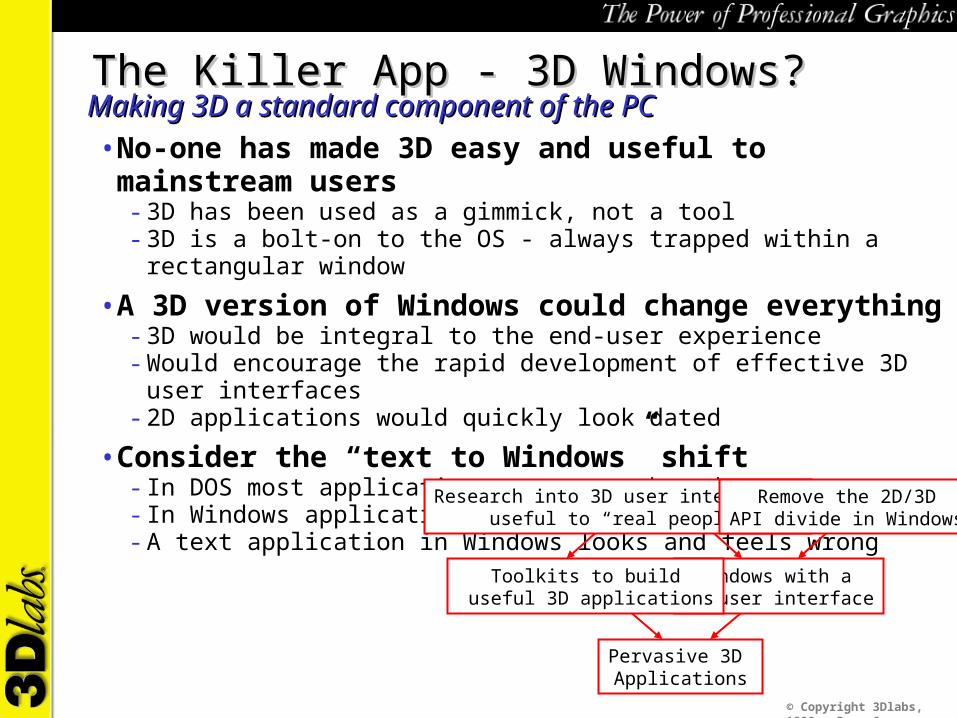
The Killer App - 3D Windows?The Killer App - 3D Windows?Making 3D a standard component of the PCMaking 3D a standard component of the PC• No-one has made 3D easy and useful to mainstream users
- 3D has been used as a gimmick, not a tool- 3D is a bolt-on to the OS - always trapped within a rectangular window
• A 3D version of Windows could change everything- 3D would be integral to the end-user experience- Would encourage the rapid development of effective 3D user interfaces- 2D applications would quickly look dated
• Consider the “text to Windows” shift- In DOS most applications were text-based- In Windows applications use the Window/2D paradigm- A text application in Windows looks and feels wrong
Pervasive 3D Applications
Windows with a 3D user interface
Toolkits to build useful 3D applications
Research into 3D user interfaces useful to “real people”
Remove the 2D/3DAPI divide in Windows
© Copyright 3Dlabs, 1999 - Page 7
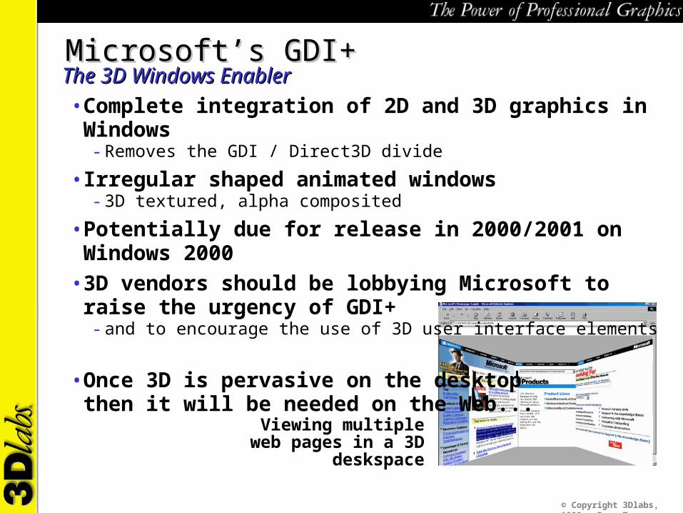
Viewing multiple web pages in a 3D deskspace
Microsoft’s GDI+Microsoft’s GDI+The 3D Windows EnablerThe 3D Windows Enabler• Complete integration of 2D and 3D graphics in Windows
- Removes the GDI / Direct3D divide
• Irregular shaped animated windows- 3D textured, alpha composited
• Potentially due for release in 2000/2001 on Windows 2000• 3D vendors should be lobbying Microsoft to raise the urgency of GDI+
- and to encourage the use of 3D user interface elements
• Once 3D is pervasive on the desktopthen it will be needed on the Web...
© Copyright 3Dlabs, 1999 - Page 8
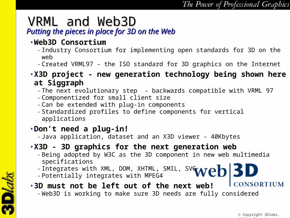
VRML and Web3DVRML and Web3DPutting the pieces in place for 3D on the WebPutting the pieces in place for 3D on the Web• Web3D Consortium
- Industry Consortium for implementing open standards for 3D on the web - Created VRML97 - the ISO standard for 3D graphics on the Internet
• X3D project - new generation technology being shown here at Siggraph- The next evolutionary step - backwards compatible with VRML 97- Componentized for small client size- Can be extended with plug-in components- Standardized profiles to define components for vertical applications
• Don’t need a plug-in!- Java application, dataset and an X3D viewer - 40Kbytes
• X3D - 3D graphics for the next generation web- Being adopted by W3C as the 3D component in new web multimedia specifications- Integrates with XML, DOM, XHTML, SMIL, SVG- Potentially integrates with MPEG4
• 3D must not be left out of the next web!- Web3D is working to make sure 3D needs are fully considered
© Copyright 3Dlabs, 1999 - Page 9
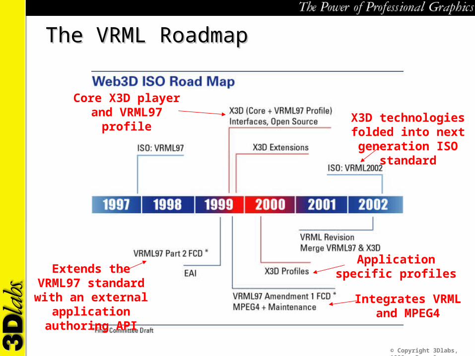
The VRML RoadmapThe VRML Roadmap
Extends the VRML97 standard with an external application authoring API
Integrates VRML and MPEG4
Core X3D player and VRML97 profile
Application specific profiles
X3D technologies folded into next generation ISO
standard

© Copyright 3Dlabs, 1999 - Page 10
How 3D Will Become PervasiveHow 3D Will Become Pervasive
Pervasive 3D Applications
Research into 3D user interfaces useful to “real people”
Windows with a 3D user interface
Remove the 2D/3DAPI divide in Windows
Toolkits to build useful 3D applications
Pervasive 3D on the Web
VRML97ISO Standard
X3D Evolutionary Web Standards
Experience with VRML97 applications
This is happening today - www.web3d.org.
© Copyright 3Dlabs, 1999 - Page 11
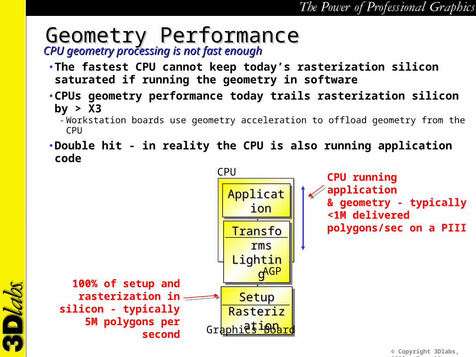
TransformsTransformsLightingLighting
TransformsTransformsLightingLighting
SetupSetupRasterizationRasterization
SetupSetupRasterizationRasterization
100% of setup and rasterization in silicon - typically 5M polygons
per second
ApplicationApplicationApplicationApplicationCPU running application& geometry - typically <1M delivered polygons/sec on a PIII
Geometry PerformanceGeometry PerformanceCPU geometry processing is not fast enoughCPU geometry processing is not fast enough• The fastest CPU cannot keep today’s rasterization silicon saturated if
running the geometry in software• CPUs geometry performance today trails rasterization silicon by > X3
- Workstation boards use geometry acceleration to offload geometry from the CPU
• Double hit - in reality the CPU is also running application code
AGP
Graphics Board
CPU
© Copyright 3Dlabs, 1999 - Page 12
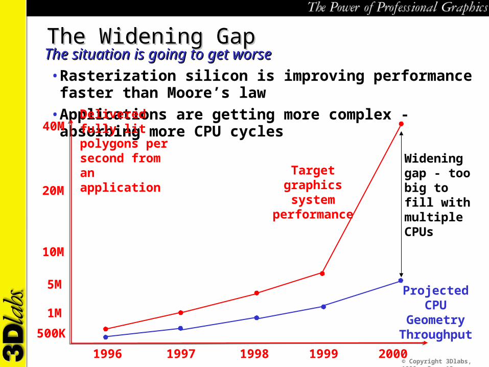
The Widening GapThe Widening GapThe situation is going to get worseThe situation is going to get worse• Rasterization silicon is improving performance faster than Moore’s law• Applications are getting more complex - absorbing more CPU cycles
19971996 1998 1999
500K
1M
5M
40M
2000
Delivered fully lit polygons per second from an application Target graphics
system performance
10M
20M
Projected CPU Geometry
Throughput
Widening gap - too big to fill with multiple CPUs

© Copyright 3Dlabs, 1999 - Page 13
3Dlabs scaleable Jetstream
architecture
Today’s hardware
GLINT500TX
19971996
Oxygen GMX
GLINT DMX 1000
1998 1999
500K
1M
3M
5M
40M
2000
Fully lit polygons per second
1 billion texture-mapped pixels per second, 40 million
polygons per second
3Dlabs Jetstream3Dlabs JetstreamFlagship performance - outpacing Moore’s LawFlagship performance - outpacing Moore’s Law
Oxygen GVX210
10M
Needs significant hardware geometry hardware
© Copyright 3Dlabs, 1999 - Page 14
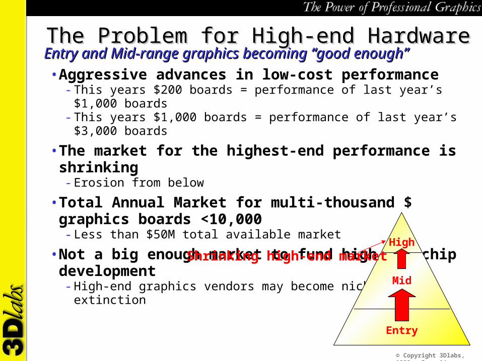
The Problem for High-end HardwareThe Problem for High-end HardwareEntry and Mid-range graphics becoming “good enough”Entry and Mid-range graphics becoming “good enough”• Aggressive advances in low-cost performance
- This years $200 boards = performance of last year’s $1,000 boards- This years $1,000 boards = performance of last year’s $3,000 boards
• The market for the highest-end performance is shrinking- Erosion from below
• Total Annual Market for multi-thousand $ graphics boards <10,000- Less than $50M total available market
• Not a big enough market to fund high-end chip development- High-end graphics vendors may become niched into extinction
HighShrinking high-end market
Mid
Entry
© Copyright 3Dlabs, 1999 - Page 15
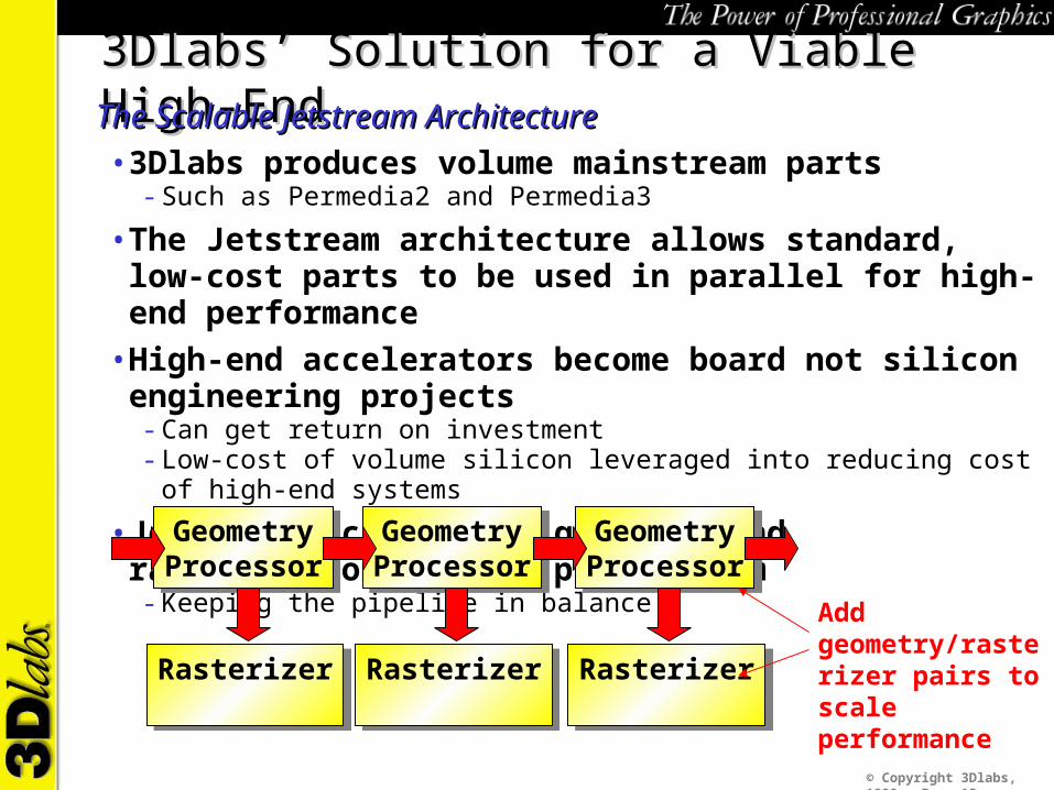
3Dlabs’ Solution for a Viable High-End3Dlabs’ Solution for a Viable High-EndThe Scalable Jetstream ArchitectureThe Scalable Jetstream Architecture• 3Dlabs produces volume mainstream parts
- Such as Permedia2 and Permedia3
• The Jetstream architecture allows standard, low-cost parts to be used in parallel for high-end performance
• High-end accelerators become board not silicon engineering projects- Can get return on investment- Low-cost of volume silicon leveraged into reducing cost of high-end systems
• Jetstream scales both geometry and rasterization through parallelism- Keeping the pipeline in balance
GeometryProcessorGeometryProcessor
RasterizerRasterizer
GeometryProcessorGeometryProcessor
RasterizerRasterizer
GeometryProcessorGeometryProcessor
RasterizerRasterizer
Add geometry/rasterizer pairs to scale performance

© Copyright 3Dlabs, 1999 - Page 16
AGP4XAGP4X
AGP4XGamma
G3
GammaG3
44M vertices/secneeds 1.2GB/sat 7 words/vertex
44 Million/sec input (vertex array)Full OpenGL 1.2 geometry and lighting pipeline
Clipping, transforms, lighting
2 independent AGP 4X busses
GLINT Gamma G3GLINT Gamma G3Geometry processor planned for 2000Geometry processor planned for 2000• 44 Million vertex/sec geometry processor
- Saturates AGP 4X with vertex data
• Full OpenGL 1.2 geometry and lighting- Up to 16 light sources on chip
• Full AGP 4X to dual AGP 4X bridge- With broadcast capability to both busses- The key to geometry and rasterization scalability

© Copyright 3Dlabs, 1999 - Page 17
Rasterizer #2 ( )Rasterizer #1
Rasterizer #2Only a fraction of polygons are processed by both Rasterizers
Rasterizer #1 ( )
Both ( )
GLINT R4 Stripe InterleavingGLINT R4 Stripe InterleavingEfficient use of multiple rasterizersEfficient use of multiple rasterizers• Rasterizers process interleaved Stripes on the screen
- 4,8,16 scan lines
• Multiplies peak fill-rate through parallel pixel processing- Striping gives better texture cache coherency than scanline interleaving
• Increases polygon throughput through distributed geometry processing- Each processor lights and sets up only the polygons that touch its stripes
© Copyright 3Dlabs, 1999 - Page 18
GammaG3
GammaG3
GLINTR4
GLINTR4
64Mbytes64Mbytes
Use RAMDAC
of one chip
GammaG3
GammaG3
GLINTR4
GLINTR4
64Mbytes64Mbytes
GammaG3
GammaG3
GLINTR4
GLINTR4
64Mbytes64Mbytes
GammaG3
GammaG3
GLINTR4
GLINTR4
64Mbytes64Mbytes
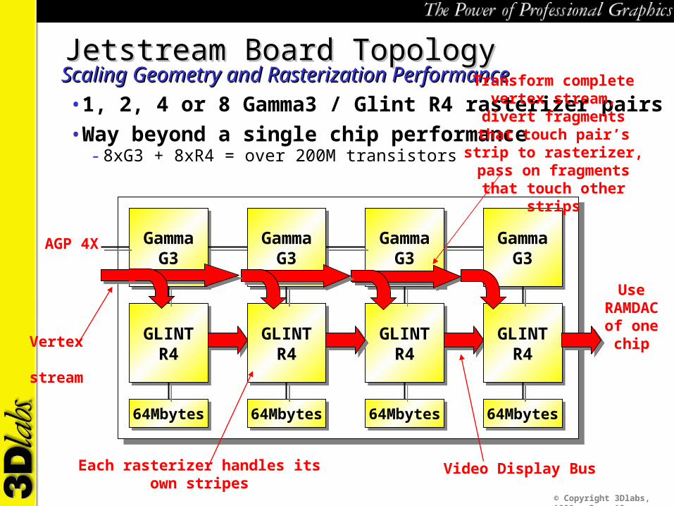
Video Display BusEach rasterizer handles its own stripes
Jetstream Board TopologyJetstream Board TopologyScaling Geometry and Rasterization PerformanceScaling Geometry and Rasterization Performance• 1, 2, 4 or 8 Gamma3 / Glint R4 rasterizer pairs• Way beyond a single chip performance
- 8xG3 + 8xR4 = over 200M transistors
AGP 4X
Transform complete vertex stream, divert fragments that
touch pair’s strip to rasterizer, pass on fragments that touch
other strips
Vertex stream

© Copyright 3Dlabs, 1999 - Page 19
Vertex Transmission BandwidthVertex Transmission BandwidthA fundamental bottleneck on the PCA fundamental bottleneck on the PC• A complex 3D vertex can take up to 30 bytes to define
- Position, normal, texture coordinates, alpha value etc. etc…- This is assuming the best case of long tri-strips - so only one vertex per polygon
• So where is the real bandwidth bottleneck?- Need to consider how vertex data is formed
Graphics
CPU
Memory
North Bridge
FSB
Memory
AGP4X
133MHz frontside bus = 1GB/s
Dual Direct Rambus channels = 3.2Gbyte/sec
AGP 4X = 1GB/s

© Copyright 3Dlabs, 1999 - Page 20
The Journey of a VertexThe Journey of a VertexA complex path through the systemA complex path through the system• Every vertex hits memory three times
- CPU reads application data- CPU writes vertex data to DMA buffer- Graphics chip reads vertex data from DMA buffer
Graphics
CPU
Memory
North Bridge
CPU reads application data
CPU writes vertex data to DMA buffer
Graphics board DMAs vertex data
© Copyright 3Dlabs, 1999 - Page 21
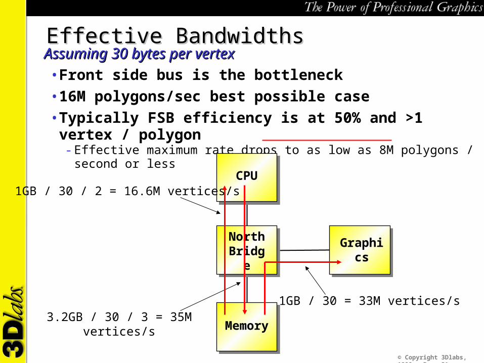
Effective BandwidthsEffective BandwidthsAssuming 30 bytes per vertexAssuming 30 bytes per vertex• Front side bus is the bottleneck• 16M polygons/sec best possible case• Typically FSB efficiency is at 50% and >1 vertex / polygon
- Effective maximum rate drops to as low as 8M polygons / second or less
Graphics
CPU
Memory
North Bridge
1GB / 30 / 2 = 16.6M vertices/s
3.2GB / 30 / 3 = 35M vertices/s
1GB / 30 = 33M vertices/s

© Copyright 3Dlabs, 1999 - Page 22
What is the solution?What is the solution?A combination of hardware and softwareA combination of hardware and software• Faster front-side bus!
- Please
• Display lists - graphics board reads stored vertices from memory- BUT 95% of real applications use immediate mode
• Smart applications should do everything reduce the amount of vertex data to be processed by the graphics pipeline
- High-level bounding box and occlusion culling- Level of detail management- High level Fahrenheit APIs provide this kind of functionality
• Vertex Compression- Pack normals and colors into minimum accuracy fields- Entropy encoding of vertex stream

© Copyright 3Dlabs, 1999 - Page 23
Long Term SolutionLong Term SolutionMore Geometry Intelligence in the Graphics PipelineMore Geometry Intelligence in the Graphics Pipeline• A new unit in the Geometry Pipeline
- Sophisticated geometry pre-processing unit- Handles higher-level vertex/geometry processing
• Needs programmability/flexibility- Complex algorithms- Subject to change - unlike the standard geometry/lighting pipeline
• Generated vertices feed standard, cost-effective hardwired geometry- Dont put standard transform, lighting calculation onto expensive programmable processors
CPUCPUIntelligentGeometry
Preprocessor
IntelligentGeometry
Preprocessor
Standard hardwired
geometry and lighting pipe
Standard hardwired
geometry and lighting pipe
Compact high-order geometry descriptions reduces CPU and
bandwidth loadsGraphics Subsystem
High-bandwidth Vertex stream generated and absorbed locally
© Copyright 3Dlabs, 1999 - Page 24
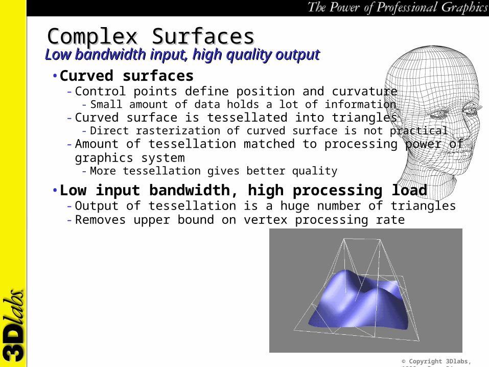
Complex SurfacesComplex SurfacesLow bandwidth input, high quality outputLow bandwidth input, high quality output• Curved surfaces
- Control points define position and curvature- Small amount of data holds a lot of information
- Curved surface is tessellated into triangles- Direct rasterization of curved surface is not practical
- Amount of tessellation matched to processing power of graphics system- More tessellation gives better quality
• Low input bandwidth, high processing load- Output of tessellation is a huge number of triangles- Removes upper bound on vertex processing rate

© Copyright 3Dlabs, 1999 - Page 25
Displacement MapsDisplacement MapsComplex surface geometryComplex surface geometry• Displacement mapping
- Tessellate surface and offset vertices according to displacement map- Displacement map looks like a texture map with each pixel holding displacement value
• Very compact representation of a lot of surface detail- Arbitrary complexity
• Next step beyond bump-mapping- Bump-mapping gives the impression of surface geometry but its just an illusion- The silhouette of the object is unchanged- Displacement maps genuinely change the objects shape
• Non-trivial implementation- Sampling and filtering the displacement map to create a surface with no gaps is tricky

© Copyright 3Dlabs, 1999 - Page 26
Surface SubdivisionSurface SubdivisionRefining input geometryRefining input geometry• The graphics pipe creates more polygons from input geometry
- Works with polygonal models or curved surfaces
• More polygons creates higher quality - with no host CPU load- Smoother surfaces, better vertex lighting precision
• Amount of output geometry can be dynamically adjusted- To match the capacity of the graphics pipe- Easy to maintain constant frame rates

© Copyright 3Dlabs, 1999 - Page 27
Vertex BlendingVertex BlendingAutomatic keyframe animation in the graphics pipeAutomatic keyframe animation in the graphics pipe• The graphics pipeline takes two vertices and blends their positions to
create an interpolated geometry• The application can create “key-frames” and then instruct the graphics
pipeline to interpolate between them• Allows the CPU to generate only one frame in N
- The graphics pipe maintains its maximum output frame rate
• No CPU or FSB load for interpolated frames- Application creates keyframes as display lists which can be DMA’d directly from memory
Graphics
Memory
North Bridge
Two key frames DMA’s from system memory

© Copyright 3Dlabs, 1999 - Page 28
Graphics Geometry IntelligenceGraphics Geometry IntelligenceHow quickly can it happen?How quickly can it happen?• Advanced geometry techniques can increase quality & reduce CPU load• But, a lot of infrastructure is needed before they will be widely used
- API support- Authoring tool support- Developer education
• The normal hardware/content chicken and egg problem- Graphics hardware has implemented other features ahead of the content- It will probably happen again

© Copyright 3Dlabs, 1999 - Page 29
The Graphics Memory DilemmaThe Graphics Memory Dilemma
19961995
OxygenGMX
GLINTDMX
1997 1998
Ever more textures, difficult to manageEver more textures, difficult to manage• Applications demanding more texture memory
- Detailed textures, multiple textures, cube maps, 3D textures
• As texture usage increases - so does the texturemanagement problem
GLINT300SX
GLINT500TX
1999
16M
96M
128M
On-board G
raphics Mem
ory
32M
64M
256M
288M
On-boardmemory
VirtualTextures
OxygenGVX1
© Copyright 3Dlabs, 1999 - Page 30
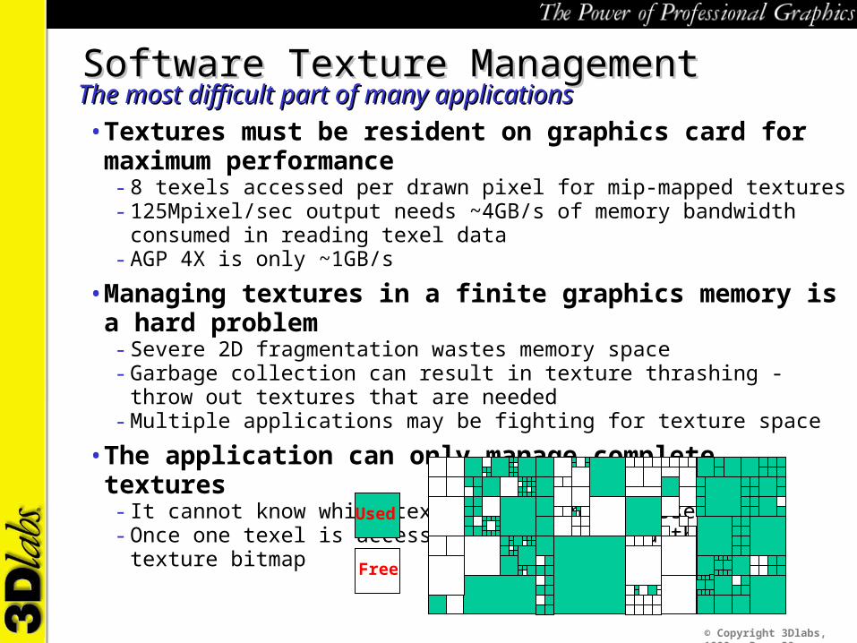
Software Texture ManagementSoftware Texture ManagementThe most difficult part of many applicationsThe most difficult part of many applications• Textures must be resident on graphics card for maximum performance
- 8 texels accessed per drawn pixel for mip-mapped textures- 125Mpixel/sec output needs ~4GB/s of memory bandwidth consumed in reading texel data- AGP 4X is only ~1GB/s
• Managing textures in a finite graphics memory is a hard problem- Severe 2D fragmentation wastes memory space- Garbage collection can result in texture thrashing - throw out textures that are needed- Multiple applications may be fighting for texture space
• The application can only manage complete textures- It cannot know which texels are being accessed- Once one texel is accessed - must download the whole texture bitmap
Free
Used
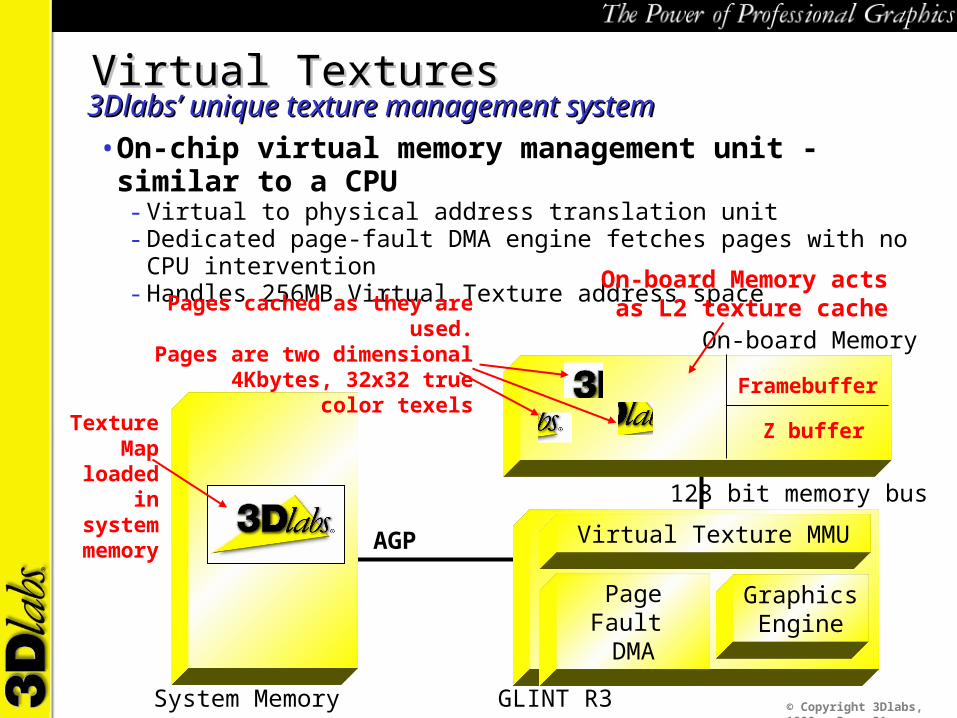
© Copyright 3Dlabs, 1999 - Page 31System Memory
GraphicsEngine
Page Fault DMA
On-board Memory
AGP
GLINT R3
Virtual Texture MMU
128 bit memory bus
Virtual TexturesVirtual Textures3Dlabs’ unique texture management system3Dlabs’ unique texture management system• On-chip virtual memory management unit - similar to a CPU
- Virtual to physical address translation unit- Dedicated page-fault DMA engine fetches pages with no CPU intervention- Handles 256MB Virtual Texture address space
Texture Map
loaded in system
memory
Pages cached as they are used.Pages are two dimensional
4Kbytes, 32x32 true color texels
Framebuffer
Z buffer
On-board Memory acts as L2 texture cache
© Copyright 3Dlabs, 1999 - Page 32
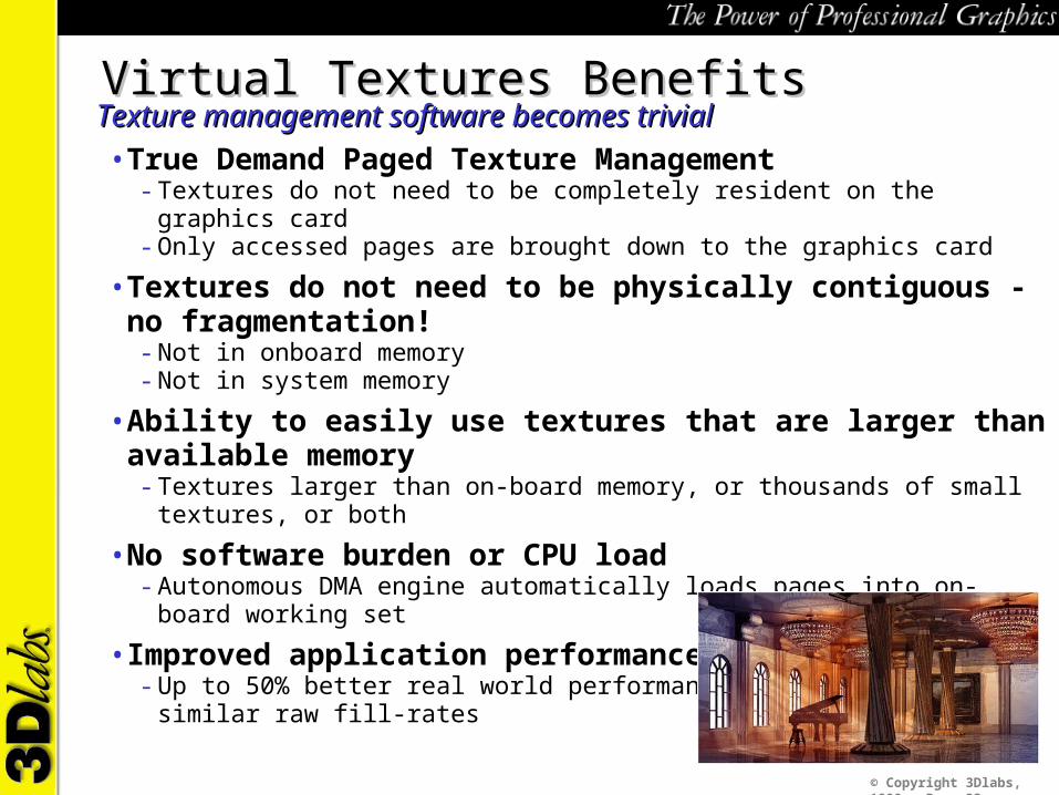
Virtual Textures BenefitsVirtual Textures BenefitsTexture management software becomes trivialTexture management software becomes trivial• True Demand Paged Texture Management
- Textures do not need to be completely resident on the graphics card- Only accessed pages are brought down to the graphics card
• Textures do not need to be physically contiguous - no fragmentation!- Not in onboard memory- Not in system memory
• Ability to easily use textures that are larger than available memory- Textures larger than on-board memory, or thousands of small textures, or both
• No software burden or CPU load- Autonomous DMA engine automatically loads pages into on-board working set
• Improved application performance- Up to 50% better real world performance over hardware with similar raw fill-rates

© Copyright 3Dlabs, 1999 - Page 33
Virtual Texturing versus UMAVirtual Texturing versus UMAPros and ConsPros and Cons• UMA can enable very low cost systems
- But adding graphics bandwidth load into main system memory can be a heavy burden
• Bandwidth load of graphics sub-system approaching 8 GB/s- Vertex stream - 1GB/s- Texture read - 4 GB/s- Framebuffer/Z buffer - 2 GB/s- Screen refresh - 1 GB/s (1920x1080x32x85Hz)
• A graphics card - the cost effective way of adding 8GB/s bandwidth?- Main system memory is the most expensive place to add more bandwidth- Absorbs framebuffer/z buffer and screen refresh bandwidth- Virtual texturing further reduces system loading
© Copyright 3Dlabs, 1999 - Page 34
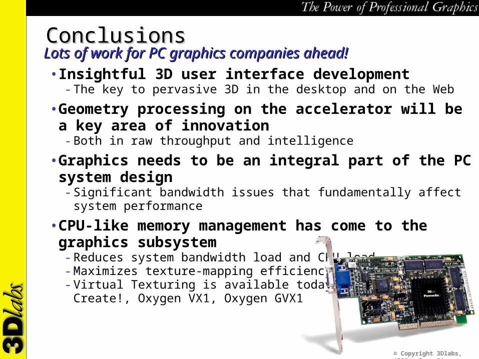
ConclusionsConclusionsLots of work for PC graphics companies ahead!Lots of work for PC graphics companies ahead!• Insightful 3D user interface development
- The key to pervasive 3D in the desktop and on the Web
• Geometry processing on the accelerator will be a key area of innovation- Both in raw throughput and intelligence
• Graphics needs to be an integral part of the PC system design- Significant bandwidth issues that fundamentally affect system performance
• CPU-like memory management has come to the graphics subsystem- Reduces system bandwidth load and CPU load- Maximizes texture-mapping efficiency and performance- Virtual Texturing is available today in the Permedia3 Create!, Oxygen VX1, Oxygen GVX1