>> CAM/CCM/CDM SHUT-OFF VALVES - ohl-gutermuth.de · >> CAM/CCM/CDM SHUT-OFF VALVES ESPECIALLY...
9
SHUT-OFF AND MODULATING SERVICE - SAFE AND ECONOMIC >>CAM/CCM/CDM SHUT-OFF VALVES ESPECIALLY DESIGNED FOR THE USE IN TAIL GAS-UNITS DN 100 - DN 2000 / 4“ - 80“ PN 2,5 - PN 40 ANSI Class 150 - 300 ANSI CLASS VI, TIGHT SHUT OFF METAL SEATED + HIGH TEMP SERVICE +
Transcript of >> CAM/CCM/CDM SHUT-OFF VALVES - ohl-gutermuth.de · >> CAM/CCM/CDM SHUT-OFF VALVES ESPECIALLY...
SHUT-OFF AND MODULATING SERVICE - SAFE AND ECONOMIC
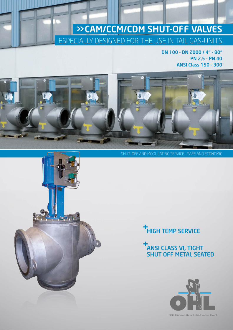
>> CAM/CCM/CDM SHUT-OFF VALVES ESPECIALLY DESIGNED FOR THE USE IN TAIL GAS-UNITS
DN 100 - DN 2000 / 4“ - 80“PN 2,5 - PN 40
ANSI Class 150 - 300
ANSI CLASS VI, TIGHT SHUT OFF METAL SEATED
+
HIGH TEMP SERVICE+
SHUT-OFF AND MODULATING SERVICE - SAFE AND ECONOMICPAGE 2
CAM/CCM/CDM JUST A FEW WORDS ABOUT OHL … …JUST A FEW WORDS ABOUT OHL
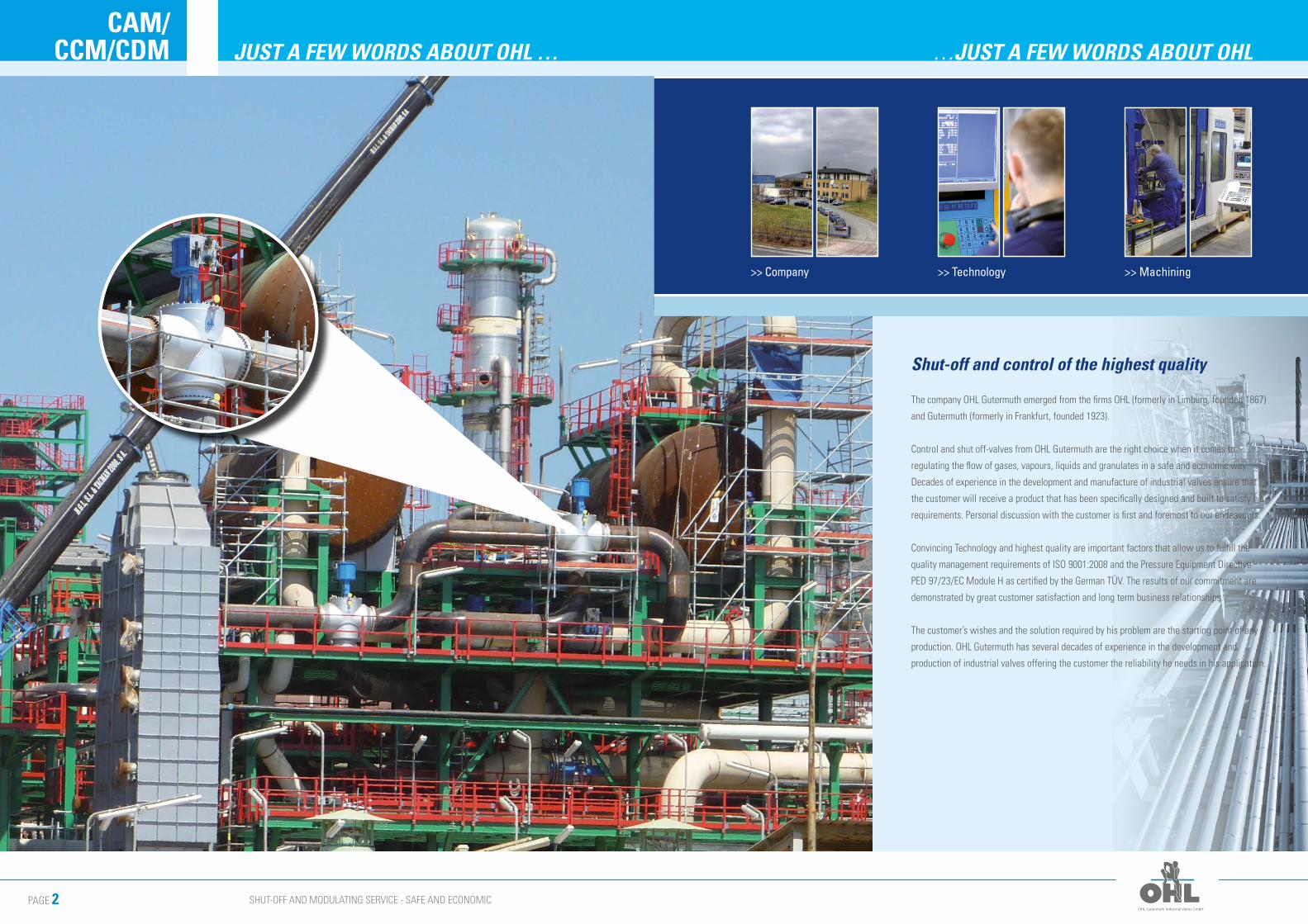
Shut-off and control of the highest quality
The company OHL Gutermuth emerged from the firms OHL (formerly in Limburg, founded 1867)
and Gutermuth (formerly in Frankfurt, founded 1923).
Control and shut off-valves from OHL Gutermuth are the right choice when it comes to
regulating the flow of gases, vapours, liquids and granulates in a safe and economic way.
Decades of experience in the development and manufacture of industrial valves ensure that
the customer will receive a product that has been specifically designed and built to satisfy his
requirements. Personal discussion with the customer is first and foremost to our endeavours.
Convincing Technology and highest quality are important factors that allow us to fulfill the
quality management requirements of ISO 9001:2008 and the Pressure Equipment Directive
PED 97/23/EC Module H as certified by the German TÜV. The results of our commitment are
demonstrated by great customer satisfaction and long term business relationships.
The customer’s wishes and the solution required by his problem are the starting point of any
production. OHL Gutermuth has several decades of experience in the development and
production of industrial valves offering the customer the reliability he needs in his application.
>> Machining>> Technology>> Company
SHUT-OFF AND MODULATING SERVICE - SAFE AND ECONOMICPAGE 4
CAM/CCM/CDM DEVELOPMENT… …APPLICATION
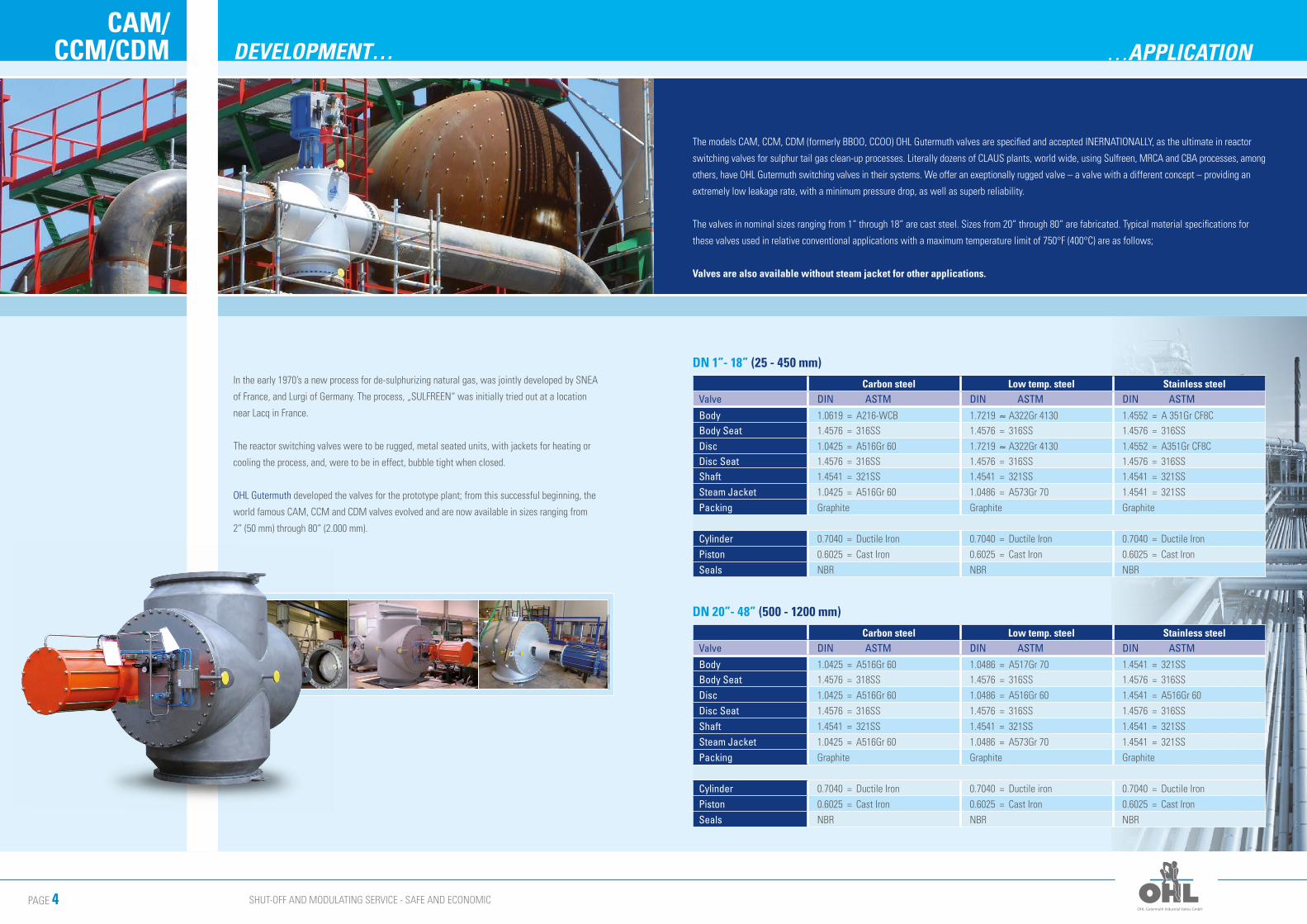
The models CAM, CCM, CDM (formerly BBOO, CCOO) OHL Gutermuth valves are specified and accepted INERNATIONALLY, as the ultimate in reactor
switching valves for sulphur tail gas clean-up processes. Literally dozens of CLAUS plants, world wide, using Sulfreen, MRCA and CBA processes, among
others, have OHL Gutermuth switching valves in their systems. We offer an exeptionally rugged valve – a valve with a different concept – providing an
extremely low leakage rate, with a minimum pressure drop, as well as superb reliability.
The valves in nominal sizes ranging from 1“ through 18“ are cast steel. Sizes from 20“ through 80“ are fabricated. Typical material specifications for
these valves used in relative conventional applications with a maximum temperature limit of 750°F (400°C) are as follows;
Valves are also available without steam jacket for other applications.
DN 1”- 18” (25 - 450 mm)
Carbon steel Low temp. steel Stainless steelValve DIN ASTM DIN ASTM DIN ASTM
Body 1.0619 = A216-WCB 1.7219 ≈ A322Gr 4130 1.4552 = A 351Gr CF8CBody Seat 1.4576 = 316SS 1.4576 = 316SS 1.4576 = 316SS
Disc 1.0425 = A516Gr 60 1.7219 ≈ A322Gr 4130 1.4552 = A351Gr CF8CDisc Seat 1.4576 = 316SS 1.4576 = 316SS 1.4576 = 316SSShaft 1.4541 = 321SS 1.4541 = 321SS 1.4541 = 321SS
Steam Jacket 1.0425 = A516Gr 60 1.0486 = A573Gr 70 1.4541 = 321SS
Packing Graphite Graphite Graphite
Cylinder 0.7040 = Ductile Iron 0.7040 = Ductile Iron 0.7040 = Ductile Iron
Piston 0.6025 = Cast Iron 0.6025 = Cast Iron 0.6025 = Cast Iron
Seals NBR NBR NBR
DN 20”- 48” (500 - 1200 mm)
Carbon steel Low temp. steel Stainless steelValve DIN ASTM DIN ASTM DIN ASTM
Body 1.0425 = A516Gr 60 1.0486 = A517Gr 70 1.4541 = 321SSBody Seat 1.4576 = 318SS 1.4576 = 316SS 1.4576 = 316SS
Disc 1.0425 = A516Gr 60 1.0486 = A516Gr 60 1.4541 = A516Gr 60
Disc Seat 1.4576 = 316SS 1.4576 = 316SS 1.4576 = 316SS
Shaft 1.4541 = 321SS 1.4541 = 321SS 1.4541 = 321SS
Steam Jacket 1.0425 = A516Gr 60 1.0486 = A573Gr 70 1.4541 = 321SS
Packing Graphite Graphite Graphite
Cylinder 0.7040 = Ductile Iron 0.7040 = Ductile iron 0.7040 = Ductile Iron
Piston 0.6025 = Cast Iron 0.6025 = Cast Iron 0.6025 = Cast Iron
Seals NBR NBR NBR
In the early 1970’s a new process for de-sulphurizing natural gas, was jointly developed by SNEA
of France, and Lurgi of Germany. The process, „SULFREEN“ was initially tried out at a location
near Lacq in France.
The reactor switching valves were to be rugged, metal seated units, with jackets for heating or
cooling the process, and, were to be in effect, bubble tight when closed.
OHL Gutermuth developed the valves for the prototype plant; from this successful beginning, the
world famous CAM, CCM and CDM valves evolved and are now available in sizes ranging from
2“ (50 mm) through 80“ (2.000 mm).
SHUT-OFF AND MODULATING SERVICE - SAFE AND ECONOMICPAGE 6
CAM/CCM/CDM TYPE CAM ANGLE BODY CONSTRUCTION... …OPERATING SPECIFICATIONS
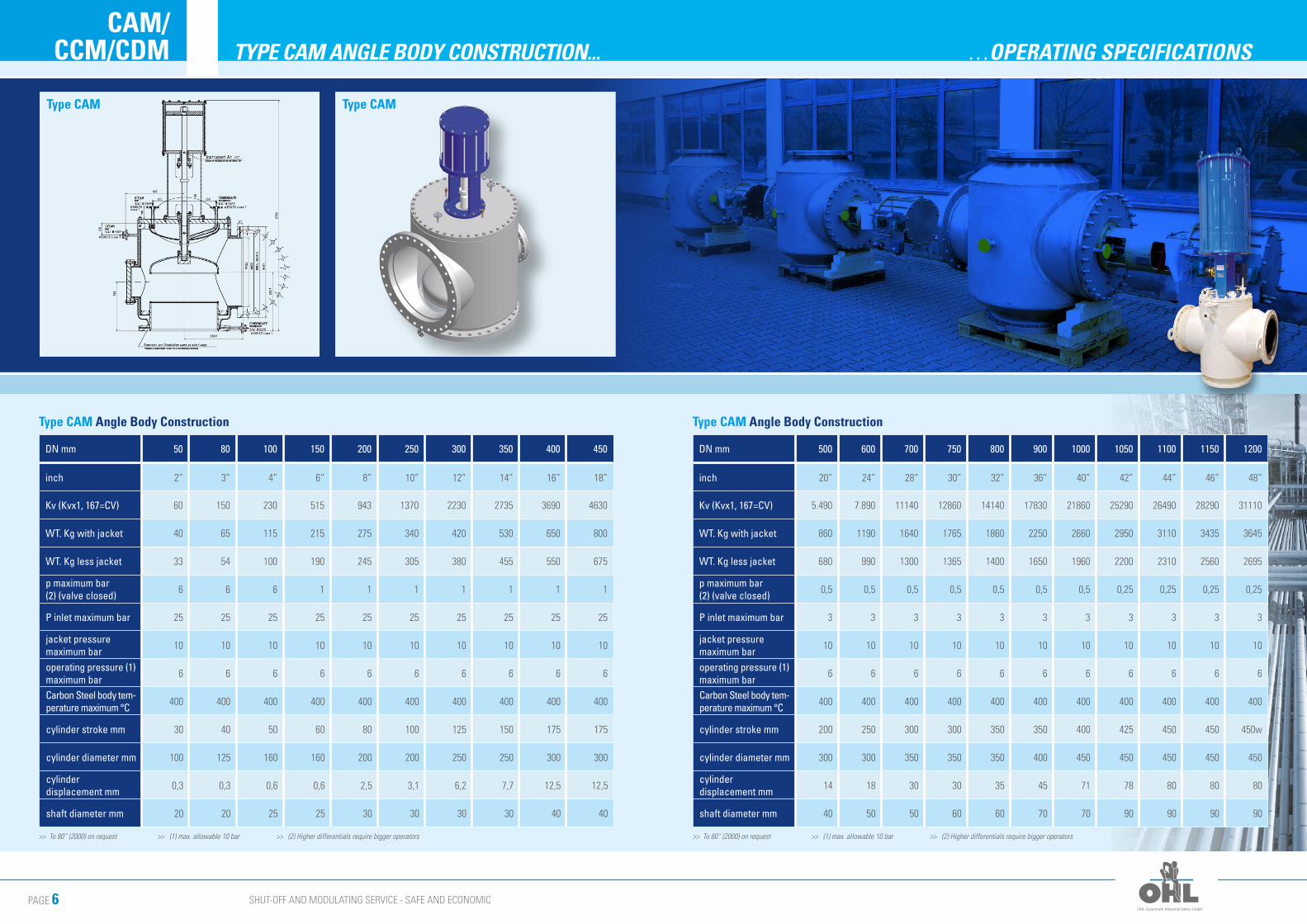
>> To 80“ (2000) on request >> (1) max. allowable 10 bar >> (2) Higher differentials require bigger operators
Type CAM Angle Body Construction
DN mm 50 80 100 150 200 250 300 350 400 450
inch 2“ 3“ 4“ 6“ 8“ 10“ 12“ 14“ 16“ 18“
Kv (Kvx1, 167=CV) 60 150 230 515 943 1370 2230 2735 3690 4630
WT. Kg with jacket 40 65 115 215 275 340 420 530 650 800
WT. Kg less jacket 33 54 100 190 245 305 380 455 550 675
p maximum bar (2) (valve closed) 6 6 6 1 1 1 1 1 1 1
P inlet maximum bar 25 25 25 25 25 25 25 25 25 25
jacket pressure maximum bar 10 10 10 10 10 10 10 10 10 10
operating pressure (1) maximum bar
6 6 6 6 6 6 6 6 6 6
Carbon Steel body tem-perature maximum °C 400 400 400 400 400 400 400 400 400 400
cylinder stroke mm 30 40 50 60 80 100 125 150 175 175
cylinder diameter mm 100 125 160 160 200 200 250 250 300 300
cylinder displacement mm 0,3 0,3 0,6 0,6 2,5 3,1 6,2 7,7 12,5 12,5
shaft diameter mm 20 20 25 25 30 30 30 30 40 40
Type CAM Angle Body Construction
DN mm 500 600 700 750 800 900 1000 1050 1100 1150 1200
inch 20“ 24“ 28“ 30“ 32“ 36“ 40“ 42“ 44“ 46“ 48“
Kv (Kvx1, 167=CV) 5.490 7.890 11140 12860 14140 17830 21860 25290 26490 28290 31110
WT. Kg with jacket 860 1190 1640 1765 1860 2250 2660 2950 3110 3435 3645
WT. Kg less jacket 680 990 1300 1365 1400 1650 1960 2200 2310 2560 2695
p maximum bar (2) (valve closed) 0,5 0,5 0,5 0,5 0,5 0,5 0,5 0,25 0,25 0,25 0,25
P inlet maximum bar 3 3 3 3 3 3 3 3 3 3 3
jacket pressure maximum bar 10 10 10 10 10 10 10 10 10 10 10
operating pressure (1) maximum bar
6 6 6 6 6 6 6 6 6 6 6
Carbon Steel body tem-perature maximum °C 400 400 400 400 400 400 400 400 400 400 400
cylinder stroke mm 200 250 300 300 350 350 400 425 450 450 450w
cylinder diameter mm 300 300 350 350 350 400 450 450 450 450 450
cylinder displacement mm 14 18 30 30 35 45 71 78 80 80 80
shaft diameter mm 40 50 50 60 60 70 70 90 90 90 90
>> To 80“ (2000) on request >> (1) max. allowable 10 bar >> (2) Higher differentials require bigger operators
Type CAM Type CAM
SHUT-OFF AND MODULATING SERVICE - SAFE AND ECONOMICPAGE 8
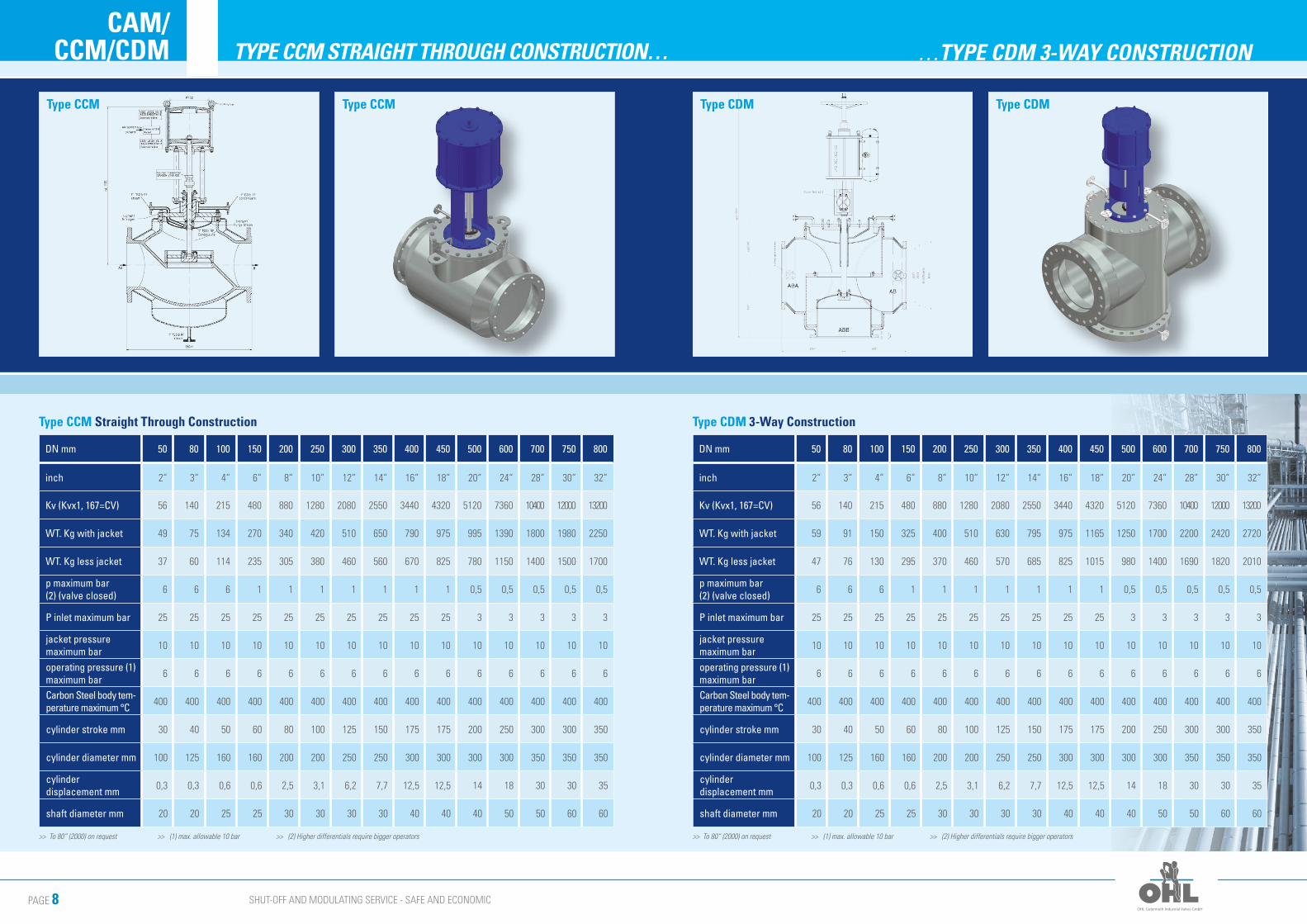
CAM/CCM/CDM TYPE CCM STRAIGHT THROUGH CONSTRUCTION… …TYPE CDM 3-WAY CONSTRUCTION
Type CCM Straight Through Construction
DN mm 50 80 100 150 200 250 300 350 400 450 500 600 700 750 800
inch 2“ 3“ 4“ 6“ 8“ 10“ 12“ 14“ 16“ 18“ 20“ 24“ 28“ 30“ 32“
Kv (Kvx1, 167=CV) 56 140 215 480 880 1280 2080 2550 3440 4320 5120 7360 10400 12000 13200
WT. Kg with jacket 49 75 134 270 340 420 510 650 790 975 995 1390 1800 1980 2250
WT. Kg less jacket 37 60 114 235 305 380 460 560 670 825 780 1150 1400 1500 1700
p maximum bar (2) (valve closed) 6 6 6 1 1 1 1 1 1 1 0,5 0,5 0,5 0,5 0,5
P inlet maximum bar 25 25 25 25 25 25 25 25 25 25 3 3 3 3 3
jacket pressure maximum bar 10 10 10 10 10 10 10 10 10 10 10 10 10 10 10
operating pressure (1) maximum bar
6 6 6 6 6 6 6 6 6 6 6 6 6 6 6
Carbon Steel body tem-perature maximum °C 400 400 400 400 400 400 400 400 400 400 400 400 400 400 400
cylinder stroke mm 30 40 50 60 80 100 125 150 175 175 200 250 300 300 350
cylinder diameter mm 100 125 160 160 200 200 250 250 300 300 300 300 350 350 350
cylinder displacement mm 0,3 0,3 0,6 0,6 2,5 3,1 6,2 7,7 12,5 12,5 14 18 30 30 35
shaft diameter mm 20 20 25 25 30 30 30 30 40 40 40 50 50 60 60
>> To 80“ (2000) on request >> (1) max. allowable 10 bar >> (2) Higher differentials require bigger operators
Type CDM 3-Way Construction
DN mm 50 80 100 150 200 250 300 350 400 450 500 600 700 750 800
inch 2“ 3“ 4“ 6“ 8“ 10“ 12“ 14“ 16“ 18“ 20“ 24“ 28“ 30“ 32“
Kv (Kvx1, 167=CV) 56 140 215 480 880 1280 2080 2550 3440 4320 5120 7360 10400 12000 13200
WT. Kg with jacket 59 91 150 325 400 510 630 795 975 1165 1250 1700 2200 2420 2720
WT. Kg less jacket 47 76 130 295 370 460 570 685 825 1015 980 1400 1690 1820 2010
p maximum bar (2) (valve closed) 6 6 6 1 1 1 1 1 1 1 0,5 0,5 0,5 0,5 0,5
P inlet maximum bar 25 25 25 25 25 25 25 25 25 25 3 3 3 3 3
jacket pressure maximum bar 10 10 10 10 10 10 10 10 10 10 10 10 10 10 10
operating pressure (1) maximum bar
6 6 6 6 6 6 6 6 6 6 6 6 6 6 6
Carbon Steel body tem-perature maximum °C 400 400 400 400 400 400 400 400 400 400 400 400 400 400 400
cylinder stroke mm 30 40 50 60 80 100 125 150 175 175 200 250 300 300 350
cylinder diameter mm 100 125 160 160 200 200 250 250 300 300 300 300 350 350 350
cylinder displacement mm 0,3 0,3 0,6 0,6 2,5 3,1 6,2 7,7 12,5 12,5 14 18 30 30 35
shaft diameter mm 20 20 25 25 30 30 30 30 40 40 40 50 50 60 60
>> To 80“ (2000) on request >> (1) max. allowable 10 bar >> (2) Higher differentials require bigger operators
Type CCM Type CCM Type CDM Type CDM
SHUT-OFF AND MODULATING SERVICE - SAFE AND ECONOMICPAGE 10
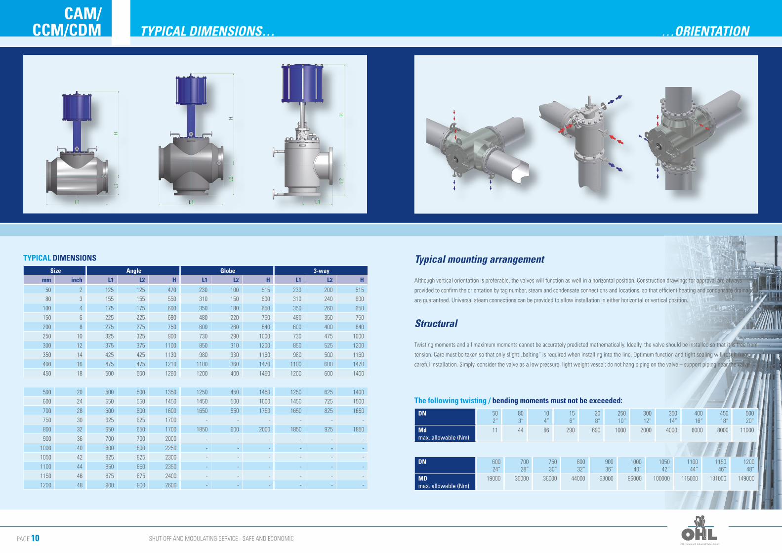
CAM/CCM/CDM …ORIENTATIONTYPICAL DIMENSIONS…
Typical mounting arrangement
Although vertical orientation is preferable, the valves will function as well in a horizontal position. Construction drawings for approval are always
provided to confirm the orientation by tag number, steam and condensate connections and locations, so that efficient heating and condensate drainage
are guaranteed. Universal steam connections can be provided to allow installation in either horizontal or vertical position.
Structural
Twisting moments and all maximum moments cannot be accurately predicted mathematically. Ideally, the valve should be installed so that it is free from
tension. Care must be taken so that only slight „bolting“ is required when installing into the line. Optimum function and tight sealing will result from
careful installation. Simply, consider the valve as a low pressure, light weight vessel; do not hang piping on the valve – support piping near the valve.
The following twisting / bending moments must not be exceeded:
DN 502“
803“
104“
156“
208“
25010“
30012“
35014“
40016“
45018“
50020“
Md max. allowable (Nm)
11 44 86 290 690 1000 2000 4000 6000 8000 11000
DN 60024“
70028“
75030“
80032“
90036“
100040“
105042“
110044“
115046“
120048“
MD max. allowable (Nm)
19000 30000 36000 44000 63000 86000 100000 115000 131000 149000
TYPICAL DIMENSIONS
Size Angle Globe 3-waymm inch L1 L2 H L1 L2 H L1 L2 H
50 2 125 125 470 230 100 515 230 200 515 80 3 155 155 550 310 150 600 310 240 600
100 4 175 175 600 350 180 650 350 260 650
150 6 225 225 690 480 220 750 480 350 750
200 8 275 275 750 600 260 840 600 400 840
250 10 325 325 900 730 290 1000 730 475 1000
300 12 375 375 1100 850 310 1200 850 525 1200
350 14 425 425 1130 980 330 1160 980 500 1160
400 16 475 475 1210 1100 360 1470 1100 600 1470
450 18 500 500 1260 1200 400 1450 1200 600 1400
500 20 500 500 1350 1250 450 1450 1250 625 1400
600 24 550 550 1450 1450 500 1600 1450 725 1500
700 28 600 600 1600 1650 550 1750 1650 825 1650
750 30 625 625 1700 - - - - - -
800 32 650 650 1700 1850 600 2000 1850 925 1850
900 36 700 700 2000 - - - - - -
1000 40 800 800 2250 - - - - - -
1050 42 825 825 2300 - - - - - -
1100 44 850 850 2350 - - - - - -
1150 46 875 875 2400 - - - - - -
1200 48 900 900 2600 - - - - - -
SHUT-OFF AND MODULATING SERVICE - SAFE AND ECONOMICPAGE 12
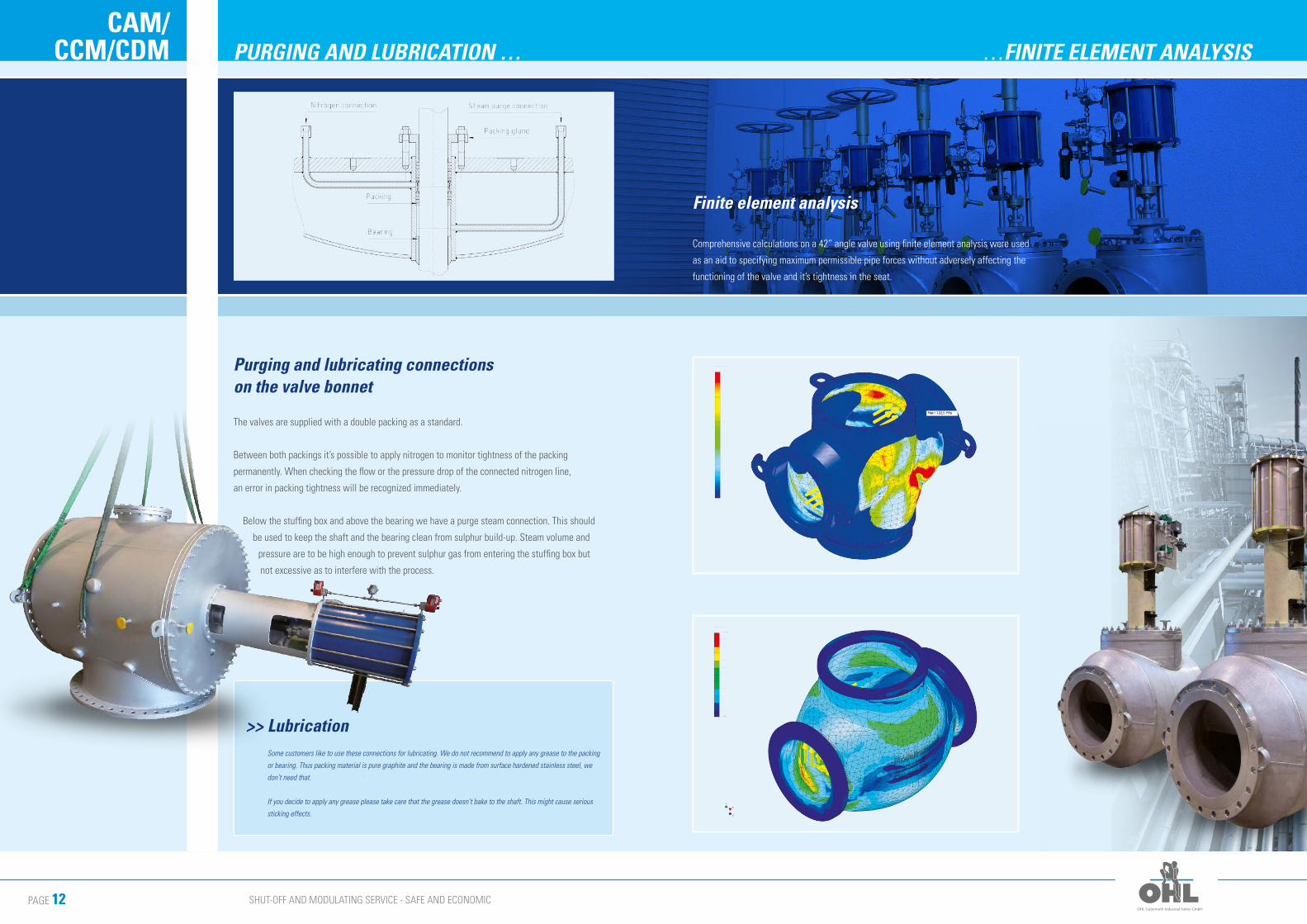
CAM/CCM/CDM …FINITE ELEMENT ANALYSISPURGING AND LUBRICATION …
>> Lubrication
Some customers like to use these connections for lubricating. We do not recommend to apply any grease to the packing
or bearing. Thus packing material is pure graphite and the bearing is made from surface hardened stainless steel, we
don’t need that.
If you decide to apply any grease please take care that the grease doesn’t bake to the shaft. This might cause serious
sticking effects.
Finite element analysis
Comprehensive calculations on a 42“ angle valve using finite element analysis were used
as an aid to specifying maximum permissible pipe forces without adversely affecting the
functioning of the valve and it’s tightness in the seat.
Purging and lubricating connections on the valve bonnet
The valves are supplied with a double packing as a standard.
Between both packings it’s possible to apply nitrogen to monitor tightness of the packing
permanently. When checking the flow or the pressure drop of the connected nitrogen line,
an error in packing tightness will be recognized immediately.
Below the stuffing box and above the bearing we have a purge steam connection. This should
be used to keep the shaft and the bearing clean from sulphur build-up. Steam volume and
pressure are to be high enough to prevent sulphur gas from entering the stuffing box but
not excessive as to interfere with the process.
SHUT-OFF AND MODULATING SERVICE - SAFE AND ECONOMICPAGE 14
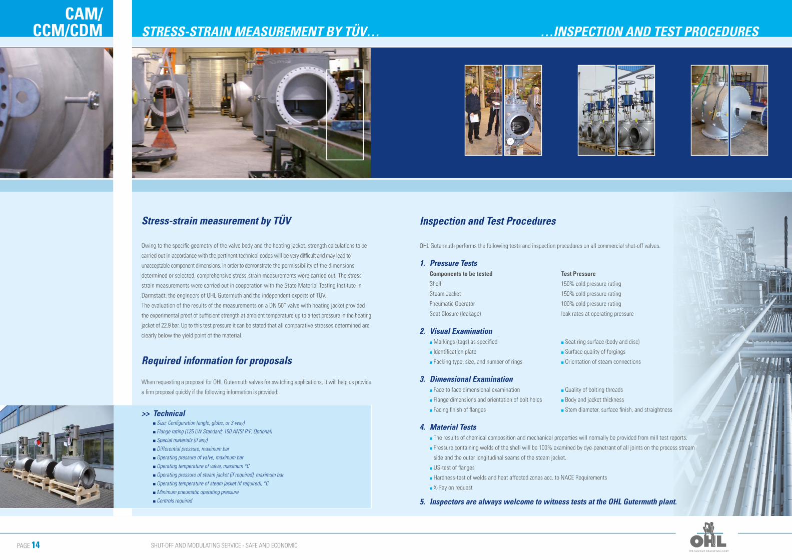
CAM/CCM/CDM …INSPECTION AND TEST PROCEDURESSTRESS-STRAIN MEASUREMENT BY TÜV…
>> Technical n Size; Configuration (angle, globe, or 3-way)
n Flange rating (125 LW Standard; 150 ANSI R:F: Optional)
n Special materials (if any)
n Differential pressure, maximum bar
n Operating pressure of valve, maximum bar
n Operating temperature of valve, maximum °C
n Operating pressure of steam jacket (if required), maximum bar
n Operating temperature of steam jacket (if required), °C
n Minimum pneumatic operating pressure
n Controls required
Stress-strain measurement by TÜV
Owing to the specific geometry of the valve body and the heating jacket, strength calculations to be
carried out in accordance with the pertinent technical codes will be very difficult and may lead to
unacceptable component dimensions. In order to demonstrate the permissibility of the dimensions
determined or selected, comprehensive stress-strain measurements were carried out. The stress-
strain measurements were carried out in cooperation with the State Material Testing Institute in
Darmstadt, the engineers of OHL Gutermuth and the independent experts of TÜV.
The evaluation of the results of the measurements on a DN 50“ valve with heating jacket provided
the experimental proof of sufficient strength at ambient temperature up to a test pressure in the heating
jacket of 22.9 bar. Up to this test pressure it can be stated that all comparative stresses determined are
clearly below the yield point of the material.
Required information for proposals
When requesting a proposal for OHL Gutermuth valves for switching applications, it will help us provide
a firm proposal quickly if the following information is provided:
1. Pressure Tests Components to be tested Test Pressure
Shell 150% cold pressure rating
Steam Jacket 150% cold pressure rating
Pneumatic Operator 100% cold pressure rating
Seat Closure (leakage) leak rates at operating pressure
2. Visual Examination n Markings (tags) as specified n Seat ring surface (body and disc)
n Identification plate n Surface quality of forgings
n Packing type, size, and number of rings n Orientation of steam connections
3. Dimensional Examination n Face to face dimensional examination n Quality of bolting threads
n Flange dimensions and orientation of bolt holes n Body and jacket thickness
n Facing finish of flanges n Stem diameter, surface finish, and straightness
4. Material Tests n The results of chemical composition and mechanical properties will normally be provided from mill test reports.
n Pressure containing welds of the shell will be 100% examined by dye-penetrant of all joints on the process stream
side and the outer longitudinal seams of the steam jacket.
n US-test of flanges
n Hardness-test of welds and heat affected zones acc. to NACE Requirements
n X-Ray on request
5. Inspectors are always welcome to witness tests at the OHL Gutermuth plant.
Inspection and Test Procedures
OHL Gutermuth performs the following tests and inspection procedures on all commercial shut-off valves.

YOUR VALVE SPECIALIST
OHL Gutermuth Industrial Valves GmbH
Helmershäuser Straße 9 + 12
63674 Altenstadt
Phone +49 (0) 60 47. 80 06 - 0
Fax +49 (0) 60 47. 80 06 - 29/36
www.ohl-gutermuth.de
ООО "OHL Gutermuth"121471, Moscow
Petra Alekseeva str.
12 build. 2, office 308.
Phone +7 495 79-79-241
web
site
:
com
pany
vi
deo:
Product Overview
KX Safeflex
KK Butterfly Valve shut-off and modulating service
GG/EE Butterfly Valve modulating service
DKK/DAK Butterfly Valve modulating service
ELL/ELS Centric Butterfly Valve
CAM/CBM Shut off valve
CCM/CDM Shut off valve
CHM Mixing Valve