㦠»Ú cÝþ CÚH ¶ ¤ 6ñÜuç µ ¨rÊU9ëT ê¿þ[c7Ðà ³ÊÚp*ÕòòK5Ì g£:#2 y · Via...
56
EC 6-708 EC 6-708 Digital controller for refrigerating power plant management Operating instructions File ec6708_eng_v1.01.pdf IMPORTANT: The use of this new instrument is easy; but for safety reasons, it is important read these instructions carefully before the installation or before the use and follow all additional informations. It is very important keep these instructions with the in- strument for future consultations. ENGLISH
Transcript of 㦠»Ú cÝþ CÚH ¶ ¤ 6ñÜuç µ ¨rÊU9ëT ê¿þ[c7Ðà ³ÊÚp*ÕòòK5Ì g£:#2 y · Via...

EC 6-708EC 6-708Digital controller for refrigeratingpower plant managementOperating instructions
File ec6708_eng_v1.01.pdf
IMPORTANT:
The use of this new instrument is easy; but for safety
reasons, it is important read these instructions carefully
before the installation or before the use and follow all
additional informations.
It is very important keep these instructions with the in-
strument for future consultations.
ENGLISH

Every Control S.r.l.
Via Mezzaterra 6, 32036 Sedico Belluno ITALY • Phone 0039-0437-852468 (a.r.) • Fax 0039-0437-83648 • [email protected] • www.everycontrol.it
2
INDEX
Summary
SUMMARY
Index page 2
Summary page 2
General informations page 3
What is the use page 3
Getting started page 4
Installation page 4
Electrical connection page 4
Instrument description page 5
Terminal blocks page 5
Keys page 5
LED page 6
Displays page 6
Before the use page 8
Settings to execute before the use page 8
Functioning page 9
Preliminary informations page 9
Suction pressure regulation page 9
Compressors protection page 10
Users total working hours counter cleaning page 11
Manual power steps loading/unloading page 11
Condensing quantity regulation page 12
Analog output page 13
Digital inputs page 13
Lower pressure alarm page 14
Upper pressure alarm page 15
Upper condensing quantity alarm page 15
Notes page 17
Summarizing flowchart page 18
Working setpoint page 24
Working setpoint setting (working suction pressure) page 24
Working setpoint page 24
Configurator Menu page 25
Configuration parameters setting page 25
Configurator Menu configuration parameters page 26
Operator Menu page 29
Configuration parameters setting page 29
Operator Menu configuration parameters page 29
User Menu page 32
Configuration parameters setting page 32
User Menu configuration parameters page 32
Configuration parameters and default values
summarizing table page 40
Configurator Menu configuration parameters page 40
Operator Menu configuration parameters page 40
User Menu configuration parameters page 42
Signals and alarms page 45
Signals page 45
Alarms page 46
Dimensional data and installation page 50
Overall dimensions page 50
Installation page 50
Electrical connection page 51
Connections to derive page 51
Technical data page 52
Technical data page 52
How to order page 52
Conversion factors page 53
Temperature page 53
Pressure page 53
Builder data page 54
Builder data page 54
Notes page 55
Notes page 55
Every Control S.r.l.
Via Mezzaterra 6, 32036 Sedico Belluno ITALY • Phone 0039-0437-852468 (a.r.) • Fax 0039-0437-83648 • [email protected] • www.everycontrol.it
3
GENERAL INFORMATIONS
What is the use
WHAT IS THE USE
EC 6-708 is a digital controller studied for refrigerating power plant
management up to eight compressors/condenser fans which basic
characteristics are the setting of the user to associate to every relay
output (condenser fans, compressor or choking valve), to subject the
compressors activation to the compressors powers and to the com-
pressors total working hours, to read and to control the suction probe
and the condensing quantity (pressure/temperature); besides, the in-
strument is provided with twelve digital inputs configurable to interact
on the relay outputs activity and with one analog output associated to
the condenser fans.
In factory the instrument gets preset to accept at the measure inputs 2
wires 4-20 mA pressure transducers/PTC probes (these last for the
condensing probe only).
EC 6-708 is available in the 160 x 90 mm (6.29 x 3.54 in., 9 DIN
modules) case and it is studied for DIN standard rail installation.
Every Control S.r.l.
Via Mezzaterra 6, 32036 Sedico Belluno ITALY • Phone 0039-0437-852468 (a.r.) • Fax 0039-0437-83648 • [email protected] • www.everycontrol.it
4
GETTING STARTED
Installation - Electrical connection
INSTALLATION
EC 6-708 was studied for DIN EN 50022 standard rail installation ac-
cording with DIN 43880 norms (see the chapter Dimensional data and
installation on the page 50).
Additional informations
• verify if the using conditions (ambient temperature, humidity,
etc.) are within the limits indicated by the builder (see the
chapter Technical data on the page 52)
• install the instrument in a location with a suitable ventilation, to
avoid the internal overheating of the instrument
• do not install the instrument near surfaces that can to obstruct
the air-grating (carpets, covers, etc.), heating sources (radia-
tors, hot air ducts, etc.), locations subject to direct sunlight,
rain, humidity, excessive dust, mechanical vibrations or bumps,
devices with strong magnetos (microwave ovens, big speak-
ers, etc.)
• according with the safety norms, the protection against possi-
ble contacts with electrical parts and parts protected with func-
tional insulation only must be ensured through a correct instal-
lation procedure of the instrument; all parts that ensure the
protection must be fixed so that they can not be removed if not
with a tool.
ELECTRICAL CONNECTION
EC 6-708 is provided with seven screw terminal blocks for cables up to
2,5 mm² (0.38 in.²) located on the instrument frontal panel (see the
chapter Electrical connection on the page 51).
Additional informations
• if the instrument is brought from a cold to a warm location, the
humidity may condense inside the instrument; wait about an
hour before supply the instrument
• verify if the operating power supply voltage, electrical fre-
quency and power of the instrument correspond to the local
power supply (see the chapter Technical data on the page 52)
• do not supply more instruments with the same transformer
• if the instrument is installed on a vehicle, its power supply must
be derived directly from the battery of the vehicle
• give the instrument a protection able to limit the current ab-
sorbed in case of failure
• the instrument remains connected to the local power supply as
long as the terminals 115 and 118 are derived to the local
power supply, even if the instrument is apparently turned off
• give the relay outputs a protection able to protect them against
short circuit and overload
• do not try to repair the instrument; for the repairs apply to
highly qualified staff
• if you have any questions or problems concerning the instru-
ment please consult Every Control (see the chapter Builder
data on the page 54).
Every Control S.r.l.
Via Mezzaterra 6, 32036 Sedico Belluno ITALY • Phone 0039-0437-852468 (a.r.) • Fax 0039-0437-83648 • [email protected] • www.everycontrol.it
5
INSTRUMENT DESCRIPTION
Terminal blocks - Keys
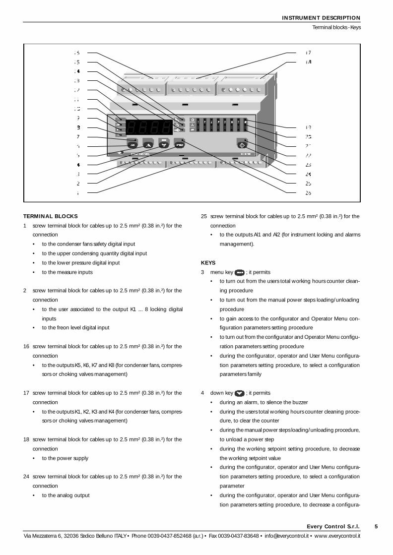
TERMINAL BLOCKS
1 screw terminal block for cables up to 2.5 mm² (0.38 in.²) for the
connection
• to the condenser fans safety digital input
• to the upper condensing quantity digital input
• to the lower pressure digital input
• to the measure inputs
2 screw terminal block for cables up to 2.5 mm² (0.38 in.²) for the
connection
• to the user associated to the output K1 ... 8 locking digital
inputs
• to the freon level digital input
16 screw terminal block for cables up to 2.5 mm² (0.38 in.²) for the
connection
• to the outputs K5, K6, K7 and K8 (for condenser fans, compres-
sors or choking valves management)
17 screw terminal block for cables up to 2.5 mm² (0.38 in.²) for the
connection
• to the outputs K1, K2, K3 and K4 (for condenser fans, compres-
sors or choking valves management)
18 screw terminal block for cables up to 2.5 mm² (0.38 in.²) for the
connection
• to the power supply
24 screw terminal block for cables up to 2.5 mm² (0.38 in.²) for the
connection
• to the analog output
25 screw terminal block for cables up to 2.5 mm² (0.38 in.²) for the
connection
• to the outputs Al1 and Al2 (for instrument locking and alarms
management).
KEYS
3 menu key ; it permits
• to turn out from the users total working hours counter clean-
ing procedure
• to turn out from the manual power steps loading/unloading
procedure
• to gain access to the configurator and Operator Menu con-
figuration parameters setting procedure
• to turn out from the configurator and Operator Menu configu-
ration parameters setting procedure
• during the configurator, operator and User Menu configura-
tion parameters setting procedure, to select a configuration
parameters family
4 down key ; it permits
• during an alarm, to silence the buzzer
• during the users total working hours counter cleaning proce-
dure, to clear the counter
• during the manual power steps loading/unloading procedure,
to unload a power step
• during the working setpoint setting procedure, to decrease
the working setpoint value
• during the configurator, operator and User Menu configura-
tion parameters setting procedure, to select a configuration
parameter
• during the configurator, operator and User Menu configura-
tion parameters setting procedure, to decrease a configura-
Every Control S.r.l.
Via Mezzaterra 6, 32036 Sedico Belluno ITALY • Phone 0039-0437-852468 (a.r.) • Fax 0039-0437-83648 • [email protected] • www.everycontrol.it
6
INSTRUMENT DESCRIPTION
Keys - LED - Displays
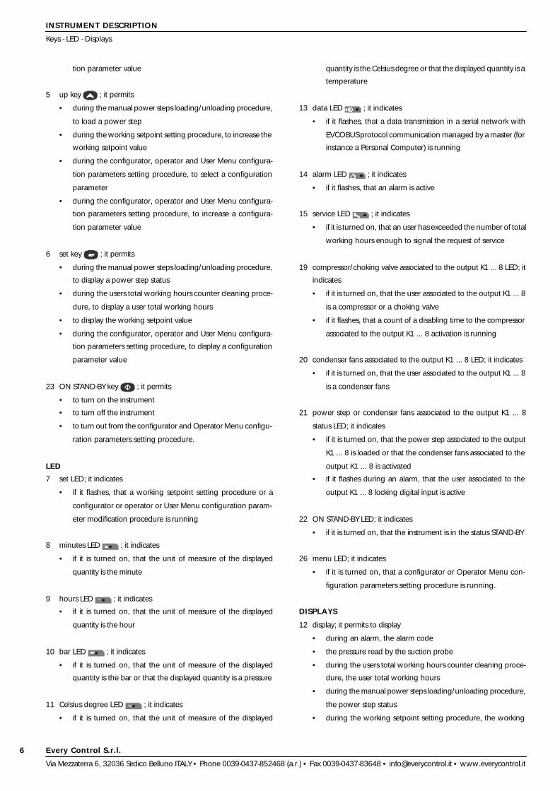
tion parameter value
5 up key ; it permits
• during the manual power steps loading/unloading procedure,
to load a power step
• during the working setpoint setting procedure, to increase the
working setpoint value
• during the configurator, operator and User Menu configura-
tion parameters setting procedure, to select a configuration
parameter
• during the configurator, operator and User Menu configura-
tion parameters setting procedure, to increase a configura-
tion parameter value
6 set key ; it permits
• during the manual power steps loading/unloading procedure,
to display a power step status
• during the users total working hours counter cleaning proce-
dure, to display a user total working hours
• to display the working setpoint value
• during the configurator, operator and User Menu configura-
tion parameters setting procedure, to display a configuration
parameter value
23 ON STAND-BY key ; it permits
• to turn on the instrument
• to turn off the instrument
• to turn out from the configurator and Operator Menu configu-
ration parameters setting procedure.
LED
7 set LED; it indicates
• if it flashes, that a working setpoint setting procedure or a
configurator or operator or User Menu configuration param-
eter modification procedure is running
8 minutes LED ; it indicates
• if it is turned on, that the unit of measure of the displayed
quantity is the minute
9 hours LED ; it indicates
• if it is turned on, that the unit of measure of the displayed
quantity is the hour
10 bar LED ; it indicates
• if it is turned on, that the unit of measure of the displayed
quantity is the bar or that the displayed quantity is a pressure
11 Celsius degree LED ; it indicates
• if it is turned on, that the unit of measure of the displayed
quantity is the Celsius degree or that the displayed quantity is a
temperature
13 data LED ; it indicates
• if it flashes, that a data transmission in a serial network with
EVCOBUS protocol communication managed by a master (for
instance a Personal Computer) is running
14 alarm LED ; it indicates
• if it flashes, that an alarm is active
15 service LED ; it indicates
• if it is turned on, that an user has exceeded the number of total
working hours enough to signal the request of service
19 compressor/choking valve associated to the output K1 ... 8 LED; it
indicates
• if it is turned on, that the user associated to the output K1 ... 8
is a compressor or a choking valve
• if it flashes, that a count of a disabling time to the compressor
associated to the output K1 ... 8 activation is running
20 condenser fans associated to the output K1 ... 8 LED; it indicates
• if it is turned on, that the user associated to the output K1 ... 8
is a condenser fans
21 power step or condenser fans associated to the output K1 ... 8
status LED; it indicates
• if it is turned on, that the power step associated to the output
K1 ... 8 is loaded or that the condenser fans associated to the
output K1 ... 8 is activated
• if it flashes during an alarm, that the user associated to the
output K1 ... 8 locking digital input is active
22 ON STAND-BY LED; it indicates
• if it is turned on, that the instrument is in the status STAND-BY
26 menu LED; it indicates
• if it is turned on, that a configurator or Operator Menu con-
figuration parameters setting procedure is running.
DISPLAYS
12 display; it permits to display
• during an alarm, the alarm code
• the pressure read by the suction probe
• during the users total working hours counter cleaning proce-
dure, the user total working hours
• during the manual power steps loading/unloading procedure,
the power step status
• during the working setpoint setting procedure, the working

Every Control S.r.l.
Via Mezzaterra 6, 32036 Sedico Belluno ITALY • Phone 0039-0437-852468 (a.r.) • Fax 0039-0437-83648 • [email protected] • www.everycontrol.it
7
INSTRUMENT DESCRIPTION
Displays
setpoint value
• during the configurator, operator and User Menu configura-
tion parameters setting procedure a configuration parameter
label
• during the configurator, operator and User Menu configura-
tion parameters setting procedure a configuration parameter
value.

Every Control S.r.l.
Via Mezzaterra 6, 32036 Sedico Belluno ITALY • Phone 0039-0437-852468 (a.r.) • Fax 0039-0437-83648 • [email protected] • www.everycontrol.it
8
BEFORE THE USE
Settings to execute before the use
SETTINGS TO EXECUTE BEFORE THE USE
To adjust the instrument to the power plant characteristics, it is impor-
tant to execute some settings before the use:
a) after supplied the instrument verify if the instrument is in the
status STAND-BY (during the status STAND-BY the display and
the LED are turned off, except the ON STAND-BY LED)
b) if the instrument is in the status ON keep pushed for two
seconds at least the ON STAND-BY key (passed two seconds
the instrument moves to the status STAND-BY)
c) set the working setpoint value (the working setpoint estab-
lishes the suction pressure associated to the compressors; see
the chapter Working setpoint on the page 24)
d) set the parameters tyP1 ... 8 value (the parameters tyP1 ... 8
establish the users to associate to the outputs K1 ... 8)
e) set the parameters Po 1 ... 8 value (the parameters Po 1 ... 8
establish a proportion among the compressors powers)
the parameters tyP1 ... 8 and Po 1 ... 8 belong to the Configurator
Menu; see the chapter Configurator Menu on the page 25
f) set the parameters /A6 and /A7 value (the parameters /A6 and
/A7 establish the lower and the upper end of scale for 4-20 mA
input of the suction transducer)
g) set the parameter /5P value (the parameter /5P establishes
where to display the decimal point)
h) set the parameter /bE value (the parameter /bE establishes
the kind of condensing probe that the instrument must recog-
nize)
i) if the condensing probe is a 2 wires 4-20 mA pressure trans-
ducer set the parameters /b6 and /b7 value (the parameters
/b6 and /b7 establish the lower and the upper end of scale for
4-20 mA input of the condensing transducer)
j) if the condensing probe is a PTC probe set the parameter / t
value (the parameter / t establishes the unit of measure with
which the temperature gets displayed)
k) set the parameter r 0 value (the parameter r 0 establishes the
“neutral zone” value of the suction pressure regulator)
l) if a compressor at least is choked set the parameter r C value
(the parameter r C establishes the kind of choking valve that
the instrument must manage)
m) set the parameter F 0 value (the parameter F 0 establishes the
proportional band width of the condenser fans regulator)
n) set the parameter F 1 value (the parameter F 1 establishes the
condensing quantity value to which the instrument activates
the condenser fans)
o) set the parameter F A value (the parameter F A establishes the
condenser fans functioning)
the parameters /A6, /A7, /5P, /bE, /b6, /b7, / t, r 0, r C, F 0, F 1 and
F A belong to the User Menu; see the chapter User Menu on the page
32.

Every Control S.r.l.
Via Mezzaterra 6, 32036 Sedico Belluno ITALY • Phone 0039-0437-852468 (a.r.) • Fax 0039-0437-83648 • [email protected] • www.everycontrol.it
9
FUNCTIONING
Preliminary informations - Suction pressure regulation
PRELIMINARY INFORMATIONS
After derived the connections (see the chapter Electrical connection on
the page 51), the instrument reproposes the last setting stored.
Keeping pushed for two seconds at least the ON STAND-BY key the
instrument turning on (status ON) or turning off (status STAND-BY),
except during the setting procedures.
During the status STAND-BY the display and the LED are turned off,
except the ON STAND-BY LED, all relay outputs are forced to the status
OFF, except the output Al1 and the analog output signal is 4 mA or 0 V.
During the status ON, in the course of the normal functioning the
instrument displays the pressure read by the suction probe.
If an alarm should be active the instrument displays the alarm code
flashing, for instance “EFAn”, the buzzer utters an intermittent beep,
the alarm LED flashes and the output Al1 gets activated (see the para-
graph Alarms on the page 46); pressure on the down key during an
alarm permits to silence the buzzer but does not modify the outputs Al1
and Al1 status.
SUCTION PRESSURE REGULATION
Suction pressure regulation happens through the compressors.
The instrument activates the compressors (it loads power steps) with
sequence when the pressure read by the suction probe rises above the
working setpoint of the “neutral zone” value and it deactivates them (it
unloads power steps) in sequence when the pressure read by the
suction probe falls below the working setpoint of the “neutral zone”
value.
The parameter r A establishes the kind of regulating action that the
instrument must manage: it is function of the pressure read by the
suction probe (in this case when the pressure read by the suction probe
is above/below the working setpoint of the “neutral zone” value the
instrument loads/unloads power steps) ...
or function of the pressure read by the suction probe and of the direc-
tion of the pressure read by the suction probe (the same action saw in
the previous case but when the pressure read by the suction probe is
above/below the working setpoint of the “neutral zone” value and it is
going towards the “neutral zone” the instrument does not load/unload
power steps).
The instrument automatically computes which compressor to activate

Every Control S.r.l.
Via Mezzaterra 6, 32036 Sedico Belluno ITALY • Phone 0039-0437-852468 (a.r.) • Fax 0039-0437-83648 • [email protected] • www.everycontrol.it
10
... or NO choking valve (in this case the instrument loads a power step
activating the compressor and it loads another power step activating
the choking valve).
Speaking of choked compressors
• the parameter r C establishes the kind of choking valve that
the instrument must manage
the parameter r C belongs to the User Menu; see the chapter User
Menu on the page 32.
COMPRESSORS PROTECTION
Some parameters permit to set the instrument to protect the compres-
sors against overloads due to several starts repeated in a short time
FUNCTIONING
Suction pressure regulation - Compressors protection
or deactivate according with the protections, the powers and the
working hours of the compressors.
Speaking of suction pressure regulation
• the parameter Hr 1 ... 8 permits to display the total working
hours of the user associated to the output K1 ... 8
• the parameter tyP1 ... 8 establishes the user to associate to the
output K1 ... 8
• the parameter Po 1 ... 8 establishes a proportion among the
compressors powers
the parameters Hr 1 ... 8, tyP1 ... 8 and Po 1 ... 8 belong to the
Configurator Menu; see the chapter Configurator Menu on the page
25
• the parameter r 0 establishes the “neutral zone” value
• the parameter r 4 establishes the percentage of “neutral zone”
value to apply below the working setpoint
• the parameter r 8 establishes the minimum time interval that
pass from the moment in which the instrument loads a power
step to the moment in which the instrument loads the follow-
ing power step
• the parameter r 9 establishes the minimum time interval that
pass from the moment in which the instrument unloads a power
step to the moment in which the instrument unloads the fol-
lowing power step
• the parameter r A establishes the kind of regulating action that
the instrument must manage
• the parameters C 0, C 1 and C 2 permit to set the instrument
to protect the compressors against overloads due to several
starts repeated in a short time (see the paragraph Compres-
sors protection on the page 10)
• the parameter C 6 establishes the number of power steps
loaded during a suction probe failure alarm (see the para-
graph Alarms on the page 46)
• the parameter C 7 establishes the number of running working
hours of a power step enough to request the power step
unloading
• the parameter C H establishes the number of total working
hours of a power step enough to signal the request of service
(see the paragraph Alarms on the page 46)
the parameters r 0, r 4, r 8, r 9, r A, C 0, C 1, C 2, C 6, C 7 and C H
belong to the User Menu; see the chapter User Menu on the page 32.
If the compressor is choked the respective choking valve will be associ-
ated to the following relay output (for instance if the compressor to
choke is associated to the output K1, the respective choking valve must
be associated to the output K2).
The parameter r C establishes the kind of choking valve that the instru-
ment must manage: NC choking valve (in this case the instrument
loads a power step activating at the same time the compressor and the
respective choking valve and it loads another power step deactivating
the choking valve) ...

Every Control S.r.l.
Via Mezzaterra 6, 32036 Sedico Belluno ITALY • Phone 0039-0437-852468 (a.r.) • Fax 0039-0437-83648 • [email protected] • www.everycontrol.it
11
FUNCTIONING
Compressors protection - Users total working hours counter cleaning - Manual power steps loading/unloading
Speaking of compressors protection
• the parameter C 0 establishes the time that disables the com-
pressor activation from the moment in which the instrument
gets supplied
• the parameter C 1 establishes the time that disables the com-
pressor activation from the moment of the previous compres-
sor activation
• the parameter C 2 establishes the time that disables the com-
pressor activation from the moment of the previous compres-
sor deactivation
the parameters C 0, C 1 and C 2 belong to the User Menu; see the
chapter User Menu on the page 32.
USERS TOTAL WORKING HOURS COUNTER CLEANING
To gain access to the users total working hours counter cleaning pro-
cedure:
a) gain access to the second level of the configurator or Opera-
tor Menu (see the chapter Configurator Menu on the page 25
or the chapter Operator Menu on the page 29)
b) push and release over and over the up or the down key as
long as the instrument displays the label of the desired user (for
instance to clear the counter of the total working hours of the
user associated to the output K2 select the label Hr 2)
c) push and release the set key (to the release of the set key the
instrument displays the actual value, for instance 7 and the set
LED flashes to indicate that a configuration parameter modifi-
cation procedure is running; passed four seconds without op-
erated with the keys the instrument automatically turns out
from the configuration parameter modification procedure).
To clear the counter:
d) keep pushed for four seconds at least the down key (passed
four seconds the instrument displays 0)
e) after the modification push and release the set key (to the
release of the set key the instrument displays the label Hr 2
again).
To turn out from the users total working hours counter cleaning proce-
dure:
f) repeat the passage n or n’ of the chapter Configurator Menu
on the page 25.
MANUAL POWER STEPS LOADING/UNLOADING
To gain access to the manual power steps loading/unloading proce-
dure:
a) gain access to the second level of the Operator Menu (see the
chapter Operator Menu on the page 29)
b) push and release over and over the up or the down key as
long as the instrument displays the label of the desired power
step (for instance to load/unload the power step associated to
the output K2 select the label St 2)
c) push and release the set key (to the release of the set key the
instrument displays the actual status, for instance OFF and the
set LED flashes to indicate that a configuration parameter
modification procedure is running; passed four seconds with-
out operated with the keys the instrument automatically turns
out from the configuration parameter modification procedure).

Every Control S.r.l.
Via Mezzaterra 6, 32036 Sedico Belluno ITALY • Phone 0039-0437-852468 (a.r.) • Fax 0039-0437-83648 • [email protected] • www.everycontrol.it
12
FUNCTIONING
Manual power steps loading/unloading - Condensing quantity regulation
To load/unload manually the power step:
d) if the actual status of the power step is OFF keep pushed for
four seconds at least the up key (passed four seconds the
instrument displays On, the new status of the power step) ...
d’) ... if the actual status of the power step is ON keep pushed for
four seconds at least the down key (passed four seconds the
instrument displays OFF, the new status of the power step)
e) after the modification push and release the set key (to the
release of the set key the instrument displays the label St 2
again).
To turn out from the manual power steps loading/unloading proce-
dure:
f) repeat the passage n or n’ of the chapter Configurator Menu
on the page 25.
Additional informations
• the manual unloading of the power step of a choked compres-
sor gives the unloading of the power step of the respective
choking valve.
CONDENSING QUANTITY REGULATION
Condensing quantity regulation happens through the condenser fans.
The parameter F A establishes the condenser fans functioning: it is
function of the quantity read by the condensing probe (in this case the
instrument automatically divides the proportional band in equal frac-
tions according with the number of relay outputs associated to the
condenser fans, for instance 4, it activates the condenser fans with
sequence every time the quantity read by the condensing probe rises
above the condenser fans activation setpoint of a fraction of propor-
tional band and it deactivates them with sequence when the quantity
read by the condensing probe falls below the value to which the
activation happened of a fraction of proportional band) ...
... or function of the power steps loading/unloading (in this case a
power step loading/unloading gives the automatic activation/deacti-
vation of a condenser fans).
The parameter F d establishes the method used by the instrument to
compute which condenser fans to activate or deactivate: with fixed
sequence (in this case if the users associated to the outputs K5, K6, K7
and K8 are condenser fans, the instrument activates them beginning
from that associated to the output K5 and it deactivates them with the
reversal method) or balancing the total working hours (in this case the
instrument activates the condenser fans with sequence beginning from
that with the lower number of total working hours and it deactivates
them with the reversal method).
Speaking of condensing quantity regulation
• the parameter Hr 1 ... 8 permits to display the total working

Every Control S.r.l.
Via Mezzaterra 6, 32036 Sedico Belluno ITALY • Phone 0039-0437-852468 (a.r.) • Fax 0039-0437-83648 • [email protected] • www.everycontrol.it
13
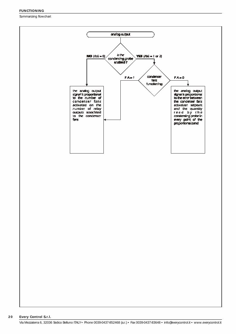
analog output signal is proportional to the number of condenser fans
activated on the number of relay outputs associated to the condenser
fans, for instance 4).
Speaking of analog output
• the parameter outF permits to display the percentage of the
analog output signal
the parameter outF belongs to the Operator Menu; see the chapter
Operator Menu on the page 29
• the parameter F 0 establishes the proportional band width
• the parameter F 1 establishes the condensing quantity value
to which the instrument activates the condenser fans
• the parameter F A establishes the condenser fans functioning
the parameters F 0, F 1 and F A belong to the use Menu; see the
chapter User Menu on the page 32.
DIGITAL INPUTS
The instrument is provided with twelve digital inputs configurable to
interact on the relay outputs activity.
Activating the user associated to the output K1 ... 8 locking digital input
the instrument activates the user associated to the output K1 ... 8
locking digital input alarm (see the paragraph Alarms on the page 46).
Activating the freon level digital input the instrument activates the freon
level digital input alarm (see the paragraph Alarms on the page 46).
Activating the condenser fans safety digital input the instrument acti-
vates the condenser fans safety digital input alarm (see the paragraph
Alarms on the page 46).
Activating the upper condensing quantity digital input the instrument
activates the upper condensing quantity digital input alarm (see the
paragraph Alarms on the page 46) and it increases an upper condens-
ing quantity alarms counter as long as the number of upper condens-
ing quantity alarms enough to give the instrument locking gets reached
(the increasing of the upper condensing quantity alarms counter gets
given also by the upper condensing quantity alarm activation; see the
paragraph Upper condensing quantity alarm on the page 15); to
unlock the instrument turn off and turn on again the instrument.
FUNCTIONING
Condensing quantity regulation - Analog output - Digital inputs
hours of the user associated to the output K1 ... 8
• the parameter tyP1 ... 8 establishes the user to associate to the
output K1 ... 8
the parameters Hr 1 ... 8 and tyP1 ... 8 belong to the Configurator
Menu; see the chapter Configurator Menu on the page 25
• the parameter Pb F permits to display the quantity read by the
condensing probe
the parameter Pb F belongs to the Operator Menu; see the chapter
Operator Menu on the page 29
• the parameter / t establishes the unit of measure with which
the temperature gets displayed
• the parameter /bE establishes the kind of condensing probe
that the instrument must recognize
• the parameter F 0 establishes the proportional band width
• the parameter F 1 establishes the condensing quantity value
to which the instrument activates the condenser fans
• the parameter F A establishes the condenser fans functioning
• the parameter F d establishes the method used by the instru-
ment to compute which condenser fans activate/deactivate
• the parameter F H establishes the number the total working
hours of a condenser fans enough to signal the request of
service (see the paragraph Alarms on the page 46)
the parameters / t, /bE, F 0, F 1, F A, F d and F H belong to the User
Menu; see the chapter User Menu on the page 32.
ANALOG OUTPUT
The 4-20 mA or 0-10 V analog output is associated to the condenser
fans.
The parameter F A establishes the condenser fans functioning and
then the analog output functioning: it is function of the quantity read by
the condensing probe (in this case the analog output signal is propor-
tional to the error between the condenser fans activation setpoint and
the quantity read by the condensing probe in every point of the pro-
portional band) ...
... or function of the power steps loading/unloading (in this case the
Every Control S.r.l.
Via Mezzaterra 6, 32036 Sedico Belluno ITALY • Phone 0039-0437-852468 (a.r.) • Fax 0039-0437-83648 • [email protected] • www.everycontrol.it
14
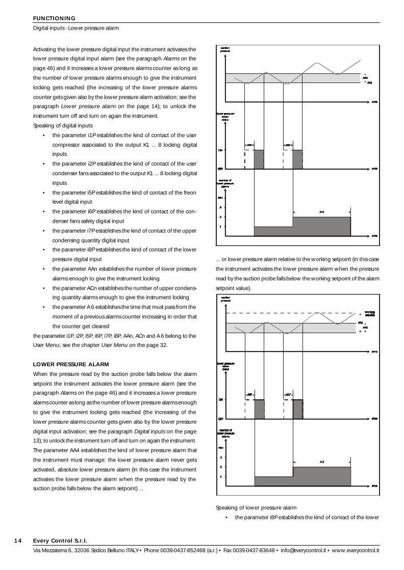
Activating the lower pressure digital input the instrument activates the
lower pressure digital input alarm (see the paragraph Alarms on the
page 46) and it increases a lower pressure alarms counter as long as
the number of lower pressure alarms enough to give the instrument
locking gets reached (the increasing of the lower pressure alarms
counter gets given also by the lower pressure alarm activation; see the
paragraph Lower pressure alarm on the page 14); to unlock the
instrument turn off and turn on again the instrument.
Speaking of digital inputs
• the parameter i1P establishes the kind of contact of the user
compressor associated to the output K1 ... 8 locking digital
inputs
• the parameter i2P establishes the kind of contact of the user
condenser fans associated to the output K1 ... 8 locking digital
inputs
• the parameter i5P establishes the kind of contact of the freon
level digital input
• the parameter i6P establishes the kind of contact of the con-
denser fans safety digital input
• the parameter i7P establishes the kind of contact of the upper
condensing quantity digital input
• the parameter i8P establishes the kind of contact of the lower
pressure digital input
• the parameter AAn establishes the number of lower pressure
alarms enough to give the instrument locking
• the parameter ACn establishes the number of upper condens-
ing quantity alarms enough to give the instrument locking
• the parameter A 6 establishes the time that must pass from the
moment of a previous alarms counter increasing in order that
the counter get cleared
the parameter i1P, i2P, i5P, i6P, i7P, i8P, AAn, ACn and A 6 belong to the
User Menu; see the chapter User Menu on the page 32.
LOWER PRESSURE ALARM
When the pressure read by the suction probe falls below the alarm
setpoint the instrument activates the lower pressure alarm (see the
paragraph Alarms on the page 46) and it increases a lower pressure
alarms counter as long as the number of lower pressure alarms enough
to give the instrument locking gets reached (the increasing of the
lower pressure alarms counter gets given also by the lower pressure
digital input activation; see the paragraph Digital inputs on the page
13); to unlock the instrument turn off and turn on again the instrument.
The parameter AA4 establishes the kind of lower pressure alarm that
the instrument must manage: the lower pressure alarm never gets
activated, absolute lower pressure alarm (in this case the instrument
activates the lower pressure alarm when the pressure read by the
suction probe falls below the alarm setpoint) ...
... or lower pressure alarm relative to the working setpoint (in this case
the instrument activates the lower pressure alarm when the pressure
read by the suction probe falls below the working setpoint of the alarm
setpoint value).
Speaking of lower pressure alarm
• the parameter i8P establishes the kind of contact of the lower
FUNCTIONING
Digital inputs - Lower pressure alarm

Every Control S.r.l.
Via Mezzaterra 6, 32036 Sedico Belluno ITALY • Phone 0039-0437-852468 (a.r.) • Fax 0039-0437-83648 • [email protected] • www.everycontrol.it
15
pressure digital input
• the parameter AA0 establishes the hysteresis (differential) rela-
tive to the alarm setpoint
• the parameter AA1 establishes the alarm setpoint value
• the parameter AA4 establishes the kind of lower pressure alarm
that the instrument must manage
• the parameter AA7 establishes the time that disables a lower
pressure alarm activation from the moment in which the lower
pressure alarm happens
• the parameter AAn establishes the number of lower pressure
alarms enough to give the instrument locking
• the parameter A 6 establishes the time that must pass from the
moment of a previous alarms counter increasing in order that
the counter get cleared
the parameters i8P, AA0, AA1, AA4, AA7, AAn and A 6 belong to the
User Menu; see the chapter User Menu on the page 32.
UPPER PRESSURE ALARM
When the pressure read by the suction probe rises above the alarm
setpoint the instrument activates the upper pressure alarm (see the
paragraph Alarms on the page 46) and it increases an upper pressure
alarms counter as long as the number of upper pressure alarms enough
to give the instrument locking gets reached; to unlock the instrument
turn off and turn on again the instrument.
The parameter Ab4 establishes the kind of upper pressure alarm that
the instrument must manage: the upper pressure alarm never gets
activated, absolute upper pressure alarm (in this case the instrument
activates the upper pressure alarm when the pressure read by the
suction probe rises above the alarm setpoint) ...
FUNCTIONING
Lower pressure alarm - Upper pressure alarm - Upper condensing quantity alarm
... or upper pressure alarm relative to the working setpoint (in this case
the instrument activates the upper pressure alarm when the pressure
read by the suction probe rises above the working setpoint of the
alarm setpoint value).
Speaking of upper pressure alarms
• the parameter Ab0 establishes the hysteresis (differential) rela-
tive to the alarm setpoint
• the parameter Ab1 establishes the alarm setpoint value
• the parameter Ab4 establishes the upper pressure alarm that
the instrument must manage
• the parameter Ab7 establishes the time that disables an upper
pressure alarm activation from the moment in which the up-
per pressure alarm happens
• the parameter Abn establishes the number of upper pressure
alarms enough to give the instrument locking
• the parameter A 3 establishes the time that disables an upper
pressure alarm activation from the moment of the instrument
start
• the parameter A 6 establishes the time that must pass from the
moment of a previous alarms counter increasing in order that
the counter get cleared
the parameters Ab0, Ab1, Ab4, Ab7, Abn, A 3 and A 6 belong to the
User Menu; see the chapter User Menu on the page 32.
UPPER CONDENSING QUANTITY ALARM
When the quantity read by the condensing probe rises above the
alarm setpoint the instrument activates the upper condensing quantity
alarm (see the paragraph Alarms on the page 46) and it increases an
Every Control S.r.l.
Via Mezzaterra 6, 32036 Sedico Belluno ITALY • Phone 0039-0437-852468 (a.r.) • Fax 0039-0437-83648 • [email protected] • www.everycontrol.it
16
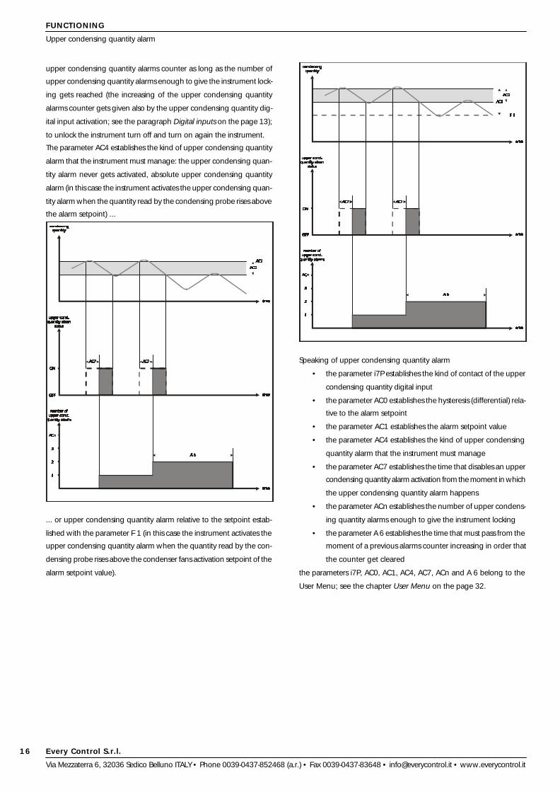
upper condensing quantity alarms counter as long as the number of
upper condensing quantity alarms enough to give the instrument lock-
ing gets reached (the increasing of the upper condensing quantity
alarms counter gets given also by the upper condensing quantity dig-
ital input activation; see the paragraph Digital inputs on the page 13);
to unlock the instrument turn off and turn on again the instrument.
The parameter AC4 establishes the kind of upper condensing quantity
alarm that the instrument must manage: the upper condensing quan-
tity alarm never gets activated, absolute upper condensing quantity
alarm (in this case the instrument activates the upper condensing quan-
tity alarm when the quantity read by the condensing probe rises above
the alarm setpoint) ...
... or upper condensing quantity alarm relative to the setpoint estab-
lished with the parameter F 1 (in this case the instrument activates the
upper condensing quantity alarm when the quantity read by the con-
densing probe rises above the condenser fans activation setpoint of the
alarm setpoint value).
Speaking of upper condensing quantity alarm
• the parameter i7P establishes the kind of contact of the upper
condensing quantity digital input
• the parameter AC0 establishes the hysteresis (differential) rela-
tive to the alarm setpoint
• the parameter AC1 establishes the alarm setpoint value
• the parameter AC4 establishes the kind of upper condensing
quantity alarm that the instrument must manage
• the parameter AC7 establishes the time that disables an upper
condensing quantity alarm activation from the moment in which
the upper condensing quantity alarm happens
• the parameter ACn establishes the number of upper condens-
ing quantity alarms enough to give the instrument locking
• the parameter A 6 establishes the time that must pass from the
moment of a previous alarms counter increasing in order that
the counter get cleared
the parameters i7P, AC0, AC1, AC4, AC7, ACn and A 6 belong to the
User Menu; see the chapter User Menu on the page 32.
FUNCTIONING
Upper condensing quantity alarm

Every Control S.r.l.
Via Mezzaterra 6, 32036 Sedico Belluno ITALY • Phone 0039-0437-852468 (a.r.) • Fax 0039-0437-83648 • [email protected] • www.everycontrol.it
17
FUNCTIONING
Notes

Every Control S.r.l.
Via Mezzaterra 6, 32036 Sedico Belluno ITALY • Phone 0039-0437-852468 (a.r.) • Fax 0039-0437-83648 • [email protected] • www.everycontrol.it
18
FUNCTIONING
Summarizing flowchart

Every Control S.r.l.
Via Mezzaterra 6, 32036 Sedico Belluno ITALY • Phone 0039-0437-852468 (a.r.) • Fax 0039-0437-83648 • [email protected] • www.everycontrol.it
19
FUNCTIONING
Summarizing flowchart
Every Control S.r.l.
Via Mezzaterra 6, 32036 Sedico Belluno ITALY • Phone 0039-0437-852468 (a.r.) • Fax 0039-0437-83648 • [email protected] • www.everycontrol.it
20
FUNCTIONING
Summarizing flowchart

Every Control S.r.l.
Via Mezzaterra 6, 32036 Sedico Belluno ITALY • Phone 0039-0437-852468 (a.r.) • Fax 0039-0437-83648 • [email protected] • www.everycontrol.it
21
FUNCTIONING
Summarizing flowchart

Every Control S.r.l.
Via Mezzaterra 6, 32036 Sedico Belluno ITALY • Phone 0039-0437-852468 (a.r.) • Fax 0039-0437-83648 • [email protected] • www.everycontrol.it
22
FUNCTIONING
Summarizing flowchart

Every Control S.r.l.
Via Mezzaterra 6, 32036 Sedico Belluno ITALY • Phone 0039-0437-852468 (a.r.) • Fax 0039-0437-83648 • [email protected] • www.everycontrol.it
23
FUNCTIONING
Summarizing flowchart
Every Control S.r.l.
Via Mezzaterra 6, 32036 Sedico Belluno ITALY • Phone 0039-0437-852468 (a.r.) • Fax 0039-0437-83648 • [email protected] • www.everycontrol.it
24
WORKING SETPOINT
Working setpoint setting (working suction pressure) - Working setpoint
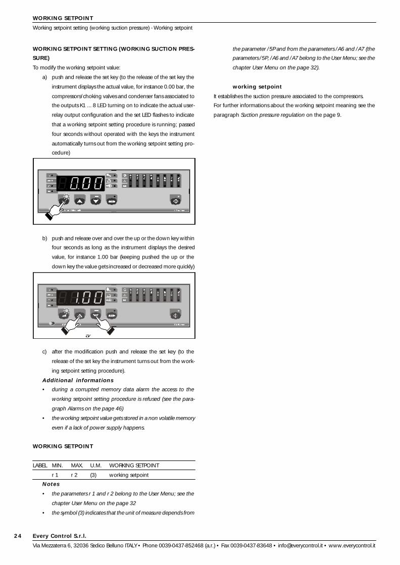
WORKING SETPOINT SETTING (WORKING SUCTION PRES-
SURE)
To modify the working setpoint value:
a) push and release the set key (to the release of the set key the
instrument displays the actual value, for instance 0.00 bar, the
compressors/choking valves and condenser fans associated to
the outputs K1 ... 8 LED turning on to indicate the actual user-
relay output configuration and the set LED flashes to indicate
that a working setpoint setting procedure is running; passed
four seconds without operated with the keys the instrument
automatically turns out from the working setpoint setting pro-
cedure)
b) push and release over and over the up or the down key within
four seconds as long as the instrument displays the desired
value, for instance 1.00 bar (keeping pushed the up or the
down key the value gets increased or decreased more quickly)
c) after the modification push and release the set key (to the
release of the set key the instrument turns out from the work-
ing setpoint setting procedure).
Additional informations
• during a corrupted memory data alarm the access to the
working setpoint setting procedure is refused (see the para-
graph Alarms on the page 46)
• the working setpoint value gets stored in a non volatile memory
even if a lack of power supply happens.
WORKING SETPOINT
LABEL MIN. MAX. U.M. WORKING SETPOINT
r 1 r 2 (3) working setpoint
Notes
• the parameters r 1 and r 2 belong to the User Menu; see the
chapter User Menu on the page 32
• the symbol (3) indicates that the unit of measure depends from
the parameter /5P and from the parameters /A6 and /A7 (the
parameters /5P, /A6 and /A7 belong to the User Menu; see the
chapter User Menu on the page 32).
working setpoint
It establishes the suction pressure associated to the compressors.
For further informations about the working setpoint meaning see the
paragraph Suction pressure regulation on the page 9.

Every Control S.r.l.
Via Mezzaterra 6, 32036 Sedico Belluno ITALY • Phone 0039-0437-852468 (a.r.) • Fax 0039-0437-83648 • [email protected] • www.everycontrol.it
25
e) after the display push and release the set key (to the release of
the set key the instrument displays the label Hr 7 again.
To gain access to the second level:
f) from the passage b keep pushed at the same time for four
seconds at least the up and the down keys (passed four sec-
onds the instrument displays the label ConF)
g) push and release the set key (to the release of the set key the
instrument displays the actual label value, for instance 0 and
the set LED flashes to indicate that a configuration parameter
modification procedure is running; passed four seconds with-
out operated with the keys the instrument automatically turns
out from a configuration parameter modification procedure)
h) push and release over and over the up or the down key within
four seconds as long as the instrument displays 113 (keeping
pushed the up or the down key the value gets increased or
decreased more quickly)
i) after the modification push and release the set key (to the
release of the set key the instrument displays Hr 1, the label of
CONFIGURATOR MENU
Configuration parameters setting
CONFIGURATION PARAMETERS SETTING
Configurator Menu configuration parameters are arranged on two
levels, to protect the most tricky settings against undesirable violations
and they are arranged in families that can be recognized through the
initial letter of the label.
To gain access to the first level:
a) verify if the instrument is in the status STAND-BY (repeat the
passages a and b of the chapter Before the use on the page 8)
b) keep pushed for two seconds at least the menu key (passed
two seconds the instrument displays the label Hr 1, the menu
LED turning on and the compressors/choking valves and con-
denser fans associated to the outputs K1 ... 8 LED turning on to
indicate the actual user-relay output configuration).
To select a parameter of the first level:
c) push and release over and over the up or the down key as
long as the instrument displays the label of the desired param-
eter, for instance Hr 7.
To display the parameter value:
d) push and release the set key (to the release of the set key the
instrument displays the actual value, for instance 26, the set
LED and the hours LED turning on to indicate respectively that
the value can not be modified and that the unit of measure of
the displayed quantity is the hour; passed four seconds without
operated with the keys the instrument automatically turns out
from a configuration parameter display procedure)
Every Control S.r.l.
Via Mezzaterra 6, 32036 Sedico Belluno ITALY • Phone 0039-0437-852468 (a.r.) • Fax 0039-0437-83648 • [email protected] • www.everycontrol.it
26
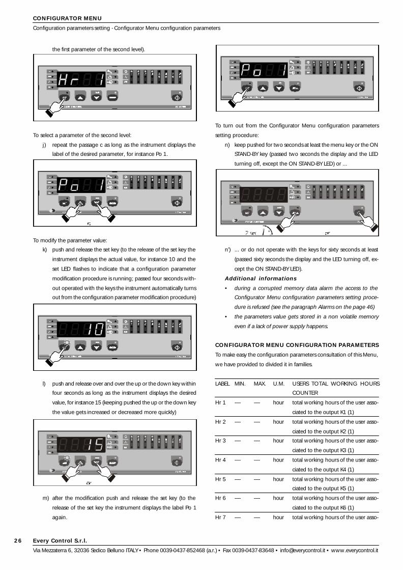
the first parameter of the second level).
To select a parameter of the second level:
j) repeat the passage c as long as the instrument displays the
label of the desired parameter, for instance Po 1.
To modify the parameter value:
k) push and release the set key (to the release of the set key the
instrument displays the actual value, for instance 10 and the
set LED flashes to indicate that a configuration parameter
modification procedure is running; passed four seconds with-
out operated with the keys the instrument automatically turns
out from the configuration parameter modification procedure)
l) push and release over and over the up or the down key within
four seconds as long as the instrument displays the desired
value, for instance 15 (keeping pushed the up or the down key
the value gets increased or decreased more quickly)
m) after the modification push and release the set key (to the
release of the set key the instrument displays the label Po 1
again.
To turn out from the Configurator Menu configuration parameters
setting procedure:
n) keep pushed for two seconds at least the menu key or the ON
STAND-BY key (passed two seconds the display and the LED
turning off, except the ON STAND-BY LED) or ...
n’) ... or do not operate with the keys for sixty seconds at least
(passed sixty seconds the display and the LED turning off, ex-
cept the ON STAND-BY LED).
Additional informations
• during a corrupted memory data alarm the access to the
Configurator Menu configuration parameters setting proce-
dure is refused (see the paragraph Alarms on the page 46)
• the parameters value gets stored in a non volatile memory
even if a lack of power supply happens.
CONFIGURATOR MENU CONFIGURATION PARAMETERS
To make easy the configuration parameters consultation of this Menu,
we have provided to divided it in families.
LABEL MIN. MAX. U.M. USERS TOTAL WORKING HOURS
COUNTER
Hr 1 ---- ---- hour total working hours of the user asso-
ciated to the output K1 (1)
Hr 2 ---- ---- hour total working hours of the user asso-
ciated to the output K2 (1)
Hr 3 ---- ---- hour total working hours of the user asso-
ciated to the output K3 (1)
Hr 4 ---- ---- hour total working hours of the user asso-
ciated to the output K4 (1)
Hr 5 ---- ---- hour total working hours of the user asso-
ciated to the output K5 (1)
Hr 6 ---- ---- hour total working hours of the user asso-
ciated to the output K6 (1)
Hr 7 ---- ---- hour total working hours of the user asso-
CONFIGURATOR MENU
Configuration parameters setting - Configurator Menu configuration parameters

Every Control S.r.l.
Via Mezzaterra 6, 32036 Sedico Belluno ITALY • Phone 0039-0437-852468 (a.r.) • Fax 0039-0437-83648 • [email protected] • www.everycontrol.it
27
ciated to the output K7 (1)
Hr 8 ---- ---- hour total working hours of the user asso-
ciated to the output K8 (1)
Notes
• the symbol (1) indicates that the parameter is available both to
the first and to the second level
• to clear the users total working hours counter see the para-
graph Users total working hours counter cleaning on the page
11.
Hr 1 total working hours of the user associated to the
output K1
It permits to display the total working hours of the user associated to the
output K1.
Hr 2 total working hours of the user associated to the
output K2
It has the same significance of the parameter Hr 1.
Hr 3 total working hours of the user associated to the
output K3
It has the same significance of the parameter Hr 1.
Hr 4 total working hours of the user associated to the
output K4
It has the same significance of the parameter Hr 1.
Hr 5 total working hours of the user associated to the
output K5
It has the same significance of the parameter Hr 1.
Hr 6 total working hours of the user associated to the
output K6
It has the same significance of the parameter Hr 1.
Hr 7 total working hours of the user associated to the
output K7
It has the same significance of the parameter Hr 1.
Hr 8 total working hours of the user associated to the
output K8
It has the same significance of the parameter Hr 1.
LABEL MIN. MAX. U.M. OPERATOR MENU PASSWORD
OPEr -999 9999 ---- Operator Menu password (2)
Notes
• the symbol (2) indicates that the parameter is available to the
first level only.
OPEr Operator Menu password
It is the password who permits to gain access to the second level of the
Operator Menu.
LABEL MIN. MAX. U.M. USER-RELAY OUTPUT CONFIGURA-
TION
tyP1 undF CHo ---- user to associate to the output K1
tyP2 undF CHo ---- user to associate to the output K2
CONFIGURATOR MENU
Configurator Menu configuration parameters
tyP3 undF CHo ---- user to associate to the output K3
tyP4 undF CHo ---- user to associate to the output K4
tyP5 undF CHo ---- user to associate to the output K5
tyP6 undF CHo ---- user to associate to the output K6
tyP7 undF CHo ---- user to associate to the output K7
tyP8 undF CHo ---- user to associate to the output K8
tyP1 user to associate to the output K1
It establishes the user to associate to the output K1, as indicated:
undF = no user associated
FAn = condenser fans
CP = compressor
Cho = choking valve.
tyP2 user to associate to the output K2
It has the same significance of the parameter tyP1.
tyP3 user to associate to the output K3
It has the same significance of the parameter tyP1.
tyP4 user to associate to the output K4
It has the same significance of the parameter tyP1.
tyP5 user to associate to the output K5
It has the same significance of the parameter tyP1.
tyP6 user to associate to the output K6
It has the same significance of the parameter tyP1.
tyP7 user to associate to the output K7
It has the same significance of the parameter tyP1.
tyP8 user to associate to the output K8
It has the same significance of the parameter tyP1.
LABEL MIN. MAX. U.M. COMPRESSORS POWER MANAGER
Po 1 1 15 ---- power of the compressor associated
to the output K1
Po 2 1 15 ---- power of the compressor associated
to the output K2
Po 3 1 15 ---- power of the compressor associated
to the output K3
Po 4 1 15 ---- power of the compressor associated
to the output K4
Po 5 1 15 ---- power of the compressor associated
to the output K5
Po 6 1 15 ---- power of the compressor associated
to the output K6
Po 7 1 15 ---- power of the compressor associated
to the output K7
Po 8 1 15 ---- power of the compressor associated
to the output K8
Po 1 power of the compressor associated to the output
K1
It is significant exclusively if the parameter tyP1 has value CP or Cho, it
establishes a proportion among the compressors powers (for instance

Every Control S.r.l.
Via Mezzaterra 6, 32036 Sedico Belluno ITALY • Phone 0039-0437-852468 (a.r.) • Fax 0039-0437-83648 • [email protected] • www.everycontrol.it
28
CONFIGURATOR MENU
Configurator Menu configuration parameters
if the power of the compressor associated to the output K1 is 4 HP and
the power of the compressor associated to the output K2 is 1 HP, set the
parameter Po 1 to 8 and the parameter Po 2 to 2.
Po 2 power of the compressor associated to the output
K2
It has the same significance of the parameter Po 1.
Po 3 power of the compressor associated to the output
K3
It has the same significance of the parameter Po 1.
Po 4 power of the compressor associated to the output
K4
It has the same significance of the parameter Po 1.
Po 5 power of the compressor associated to the output
K5
It has the same significance of the parameter Po 1.
Po 6 power of the compressor associated to the output
K6
It has the same significance of the parameter Po 1.
Po 7 power of the compressor associated to the output
K7
It has the same significance of the parameter Po 1.
Po 8 power of the compressor associated to the output
K8
It has the same significance of the parameter Po 1.
Every Control S.r.l.
Via Mezzaterra 6, 32036 Sedico Belluno ITALY • Phone 0039-0437-852468 (a.r.) • Fax 0039-0437-83648 • [email protected] • www.everycontrol.it
29
OPERATOR MENU
Configuration parameters setting - Operator Menu configuration parameters
CONFIGURATION PARAMETERS SETTING
Operator Menu configuration parameters are arranged on two lev-
els, to protect the most tricky settings against undesirable violations and
they are arranged in families that can be recognized through the initial
letter of the label.
To gain access to the first level:
a) repeat the passage b of the chapter Configurator Menu on
the page 25.
To select a parameter of the first level:
b) repeat the passage c of the chapter Configurator Menu on
the page 25.
To display the parameter value:
c) repeat the passages d and e of the chapter Configurator
Menu on the page 25.
To gain access of the second level:
d) repeat the passage c of the chapter Configurator Menu on
the page 25 as long as the instrument displays the label OPEr
e) repeat the passage g of the chapter Configurator Menu on
the page 25.
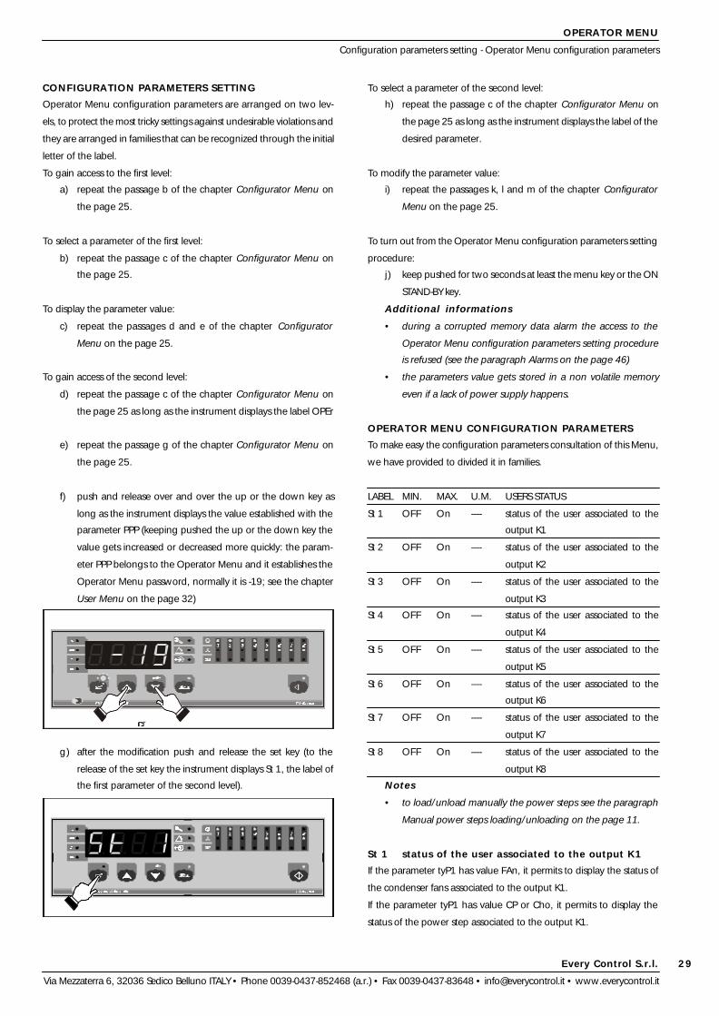
f) push and release over and over the up or the down key as
long as the instrument displays the value established with the
parameter PPP (keeping pushed the up or the down key the
value gets increased or decreased more quickly: the param-
eter PPP belongs to the Operator Menu and it establishes the
Operator Menu password, normally it is -19; see the chapter
User Menu on the page 32)
g) after the modification push and release the set key (to the
release of the set key the instrument displays St 1, the label of
the first parameter of the second level).
To select a parameter of the second level:
h) repeat the passage c of the chapter Configurator Menu on
the page 25 as long as the instrument displays the label of the
desired parameter.
To modify the parameter value:
i) repeat the passages k, l and m of the chapter Configurator
Menu on the page 25.
To turn out from the Operator Menu configuration parameters setting
procedure:
j) keep pushed for two seconds at least the menu key or the ON
STAND-BY key.
Additional informations
• during a corrupted memory data alarm the access to the
Operator Menu configuration parameters setting procedure
is refused (see the paragraph Alarms on the page 46)
• the parameters value gets stored in a non volatile memory
even if a lack of power supply happens.
OPERATOR MENU CONFIGURATION PARAMETERS
To make easy the configuration parameters consultation of this Menu,
we have provided to divided it in families.
LABEL MIN. MAX. U.M. USERS STATUS
St 1 OFF On ---- status of the user associated to the
output K1
St 2 OFF On ---- status of the user associated to the
output K2
St 3 OFF On ---- status of the user associated to the
output K3
St 4 OFF On ---- status of the user associated to the
output K4
St 5 OFF On ---- status of the user associated to the
output K5
St 6 OFF On ---- status of the user associated to the
output K6
St 7 OFF On ---- status of the user associated to the
output K7
St 8 OFF On ---- status of the user associated to the
output K8
Notes
• to load/unload manually the power steps see the paragraph
Manual power steps loading/unloading on the page 11.
St 1 status of the user associated to the output K1
If the parameter tyP1 has value FAn, it permits to display the status of
the condenser fans associated to the output K1.
If the parameter tyP1 has value CP or Cho, it permits to display the
status of the power step associated to the output K1.
Every Control S.r.l.
Via Mezzaterra 6, 32036 Sedico Belluno ITALY • Phone 0039-0437-852468 (a.r.) • Fax 0039-0437-83648 • [email protected] • www.everycontrol.it
30
OPERATOR MENU
Operator Menu configuration parameters
St 2 status of the user associated to the output K2
It has the same significance of the parameter St 1.
St 3 status of the user associated to the output K3
It has the same significance of the parameter St 1.
St 4 status of the user associated to the output K4
It has the same significance of the parameter St 1.
St 5 status of the user associated to the output K5
It has the same significance of the parameter St 1.
St 6 status of the user associated to the output K6
It has the same significance of the parameter St 1.
St 7 status of the user associated to the output K7
It has the same significance of the parameter St 1.
St 8 status of the user associated to the output K8
It has the same significance of the parameter St 1.
LABEL MIN. MAX. U.M. USERS TOTAL WORKING HOURS
COUNTER
Hr 1 ... 8 total working hours of the user asso-
ciated to the output K1 ... 8
It has the same significance of the family Hr of the Configurator Menu;
see the chapter Configurator Menu on the page 25.
LABEL MIN. MAX. U.M. OPERATOR MENU PASSWORD
OPEr -999 9999 ---- Operator Menu password
It has the same significance of the parameter OPEr of the Configurator
Menu; see the chapter Configurator Menu on the page 25.
LABEL MIN. MAX. U.M. COMPRESSORS POWER MANAGER
Po 1 ... 8 power of the compressor associated
to the output K1 ... 8
It has the same significance of the family Po of the Configurator Menu;
see the chapter Configurator Menu on the page 25.
LABEL MIN. MAX. U.M. USERS RUNNING WORKING HOURS
COUNTER
t r1 ---- ---- hour running working hours of the user
associated to the output K1
t r2 ---- ---- hour running working hours of the user
associated to the output K2
t r3 ---- ---- hour running working hours of the user
associated to the output K3
t r4 ---- ---- hour running working hours of the user
associated to the output K4
t r5 ---- ---- hour running working hours of the user
associated to the output K5
t r6 ---- ---- hour running working hours of the user
associated to the output K6
t r7 ---- ---- hour running working hours of the user
associated to the output K7
t r8 ---- ---- hour running working hours of the user
associated to the output K8
t r1 running working hours of the user associated to
the output K1
It permits to display the running working hours of the user associated to
the output K1 from the moment of the previous user activation.
t r2 running working hours of the user associated to
the output K2
It has the same significance of the parameter t r1.
t r3 running working hours of the user associated to
the output K3
It has the same significance of the parameter t r1.
t r4 running working hours of the user associated to
the output K4
It has the same significance of the parameter t r1.
t r5 running working hours of the user associated to
the output K5
It has the same significance of the parameter t r1.
t r6 running working hours of the user associated to
the output K6
It has the same significance of the parameter t r1.
t r7 running working hours of the user associated to
the output K7
It has the same significance of the parameter t r1.
t r8 running working hours of the user associated to
the output K8
It has the same significance of the parameter t r1.
LABEL MIN. MAX. U.M. ALARM CODES READING
ALAr ---- ---- ---- alarms code reading
ALAr alarm codes reading
If an alarm should be active, it permits to display the alarm code flash-
ing.
LABEL MIN. MAX. U.M. PROBES READING
Pb r ---- ---- (3) suction probe reading
Pb F ---- ---- (4) condensing probe reading (5)
Notes
• the symbol (3) indicates that the unit of measure depends from
the parameter /5P and from the parameters /A6 and /A7 (the
parameters /5P, /A6 and /A7 belong to the User Menu; see the
chapter User Menu on the page 32)
• the symbol (4) indicates that the unit of measure depends from
the parameter /bE (the parameter /bE belongs to the User
Menu; see the chapter User Menu on the page 32): if the
condensing probe is a 2 wires 4-20 mA pressure transducer
the unit of measure depends from the parameters /5P, /b6
and /b7 (the parameters /5P, /b6 and /b7 belong to the User
Menu; see the chapter User Menu on the page 32), if the
Every Control S.r.l.
Via Mezzaterra 6, 32036 Sedico Belluno ITALY • Phone 0039-0437-852468 (a.r.) • Fax 0039-0437-83648 • [email protected] • www.everycontrol.it
31
OPERATOR MENU
Operator Menu configuration parameters
condensing probe is a PTC probe the unit of measure depends
from the parameter / t (the parameter / t belongs to the User
Menu; see the chapter User Menu on the page 32)
• the symbol (5) indicates that during the status ON the param-
eter is available both to the first and to the second level.
Pb r suction probe reading
It permits to display the pressure read by the suction probe.
Pb F condensing probe reading
It permits to display the quantity read by the condensing probe.
LABEL MIN. MAX. U.M. ANALOG OUTPUT READING
outF 0 100 % analog output reading (5)
Notes
• the symbol (5) indicates that during the status ON the param-
eter is available both to the first and to the second level.
outF analog output reading
It permits to display the analog output signal percentage.
For further informations about the parameter outF meaning see the
paragraph Analog output on the page 13.
LABEL MIN. MAX. U.M. CONDENSER FANS REGULATOR
F 1 F 6 F 7 (4) condenser fans activation setpoint (5)
Notes
• the parameters F 6 and F 7 belong to the User Menu; see the
chapter User Menu on the page 32
• the symbol (4) indicates that the unit of measure depends from
the parameter /bE (the parameter /bE belongs to the User
Menu; see the chapter User Menu on the page 32): if the
condensing probe is a 2 wires 4-20 mA pressure transducer
the unit of measure depends from the parameters /5P, /b6
and /b7 (the parameters /5P, /b6 and /b7 belong to the User
Menu; see the chapter User Menu on the page 32), if the
condensing probe is a PTC probe the unit of measure depends
from the parameter / t (the parameter / t belongs to the User
Menu; see the chapter User Menu on the page 32)
• the symbol (5) indicates that during the status ON the param-
eter is available both to the first and to the second level.
F 1 condenser fans activation setpoint
It has significance exclusively if the parameter /bE has value 1 or 2 and
if the parameter F A has value 0, it establishes the condensing quantity
value to which the instrument activates the condenser fans and it is
referred to the condensing probe.
The parameter /bE and F A belong to the User Menu; see the chapter
User Menu on the page 32.
For further informations about the parameter F 1 meaning see the
paragraph Condensing quantity regulation on the page 12.

Every Control S.r.l.
Via Mezzaterra 6, 32036 Sedico Belluno ITALY • Phone 0039-0437-852468 (a.r.) • Fax 0039-0437-83648 • [email protected] • www.everycontrol.it
32
USER MENU
Configuration parameters setting - User Menu configuration parameters
CONFIGURATION PARAMETERS SETTING
User Menu configuration parameters are arranged on two levels, to
protect the most tricky settings against undesirable violations and they
are arranged in families that can be recognized through the initial
letter of the label.
To gain access to the first level:
a) keep pushed at the same time for four seconds at least the up
and the down keys (passed four seconds the instrument dis-
plays the label PA).
To select a parameter of the first level:
b) repeat the passage c of the chapter Configurator Menu on
the page 25.
To modify the parameter value:
c) repeat the passages k, l and m of the chapter Configurator
Menu on the page 25.
To gain access to the second level:
d) repeat the passage c of the chapter Configurator Menu on
the page 25 as long as the instrument displays the label PA
e) repeat the passage g of the chapter Configurator Menu on
the page 25
f) push and release over and over the up or the down key within
four seconds as long as the instrument displays -19 (keeping
pushed the up or the down key the value gets increased or
decreased more quickly)
g) after the modification push and release the set key (to the
release of the set key the instrument displays the label PA
again)
h) keep pushed at the same time for four seconds at least the up
and the down key (passed four seconds the instrument dis-
plays /A1, the label of the first parameter of the second level).
To select a parameter of the second level:
i) repeat the passage c of the chapter Configurator Menu on
the page 25 as long as the instrument displays la label of the
desired parameter.
To modify the parameter value:
j) repeat the passages k, l and m of the chapter Configurator
Menu on the page 25.
To turn out from the User Menu configuration parameters setting
procedure:
k) keep pushed at the same time for four seconds at least the up
and the down keys or do not operate with the keys for sixty
seconds at least.
Additional informations
• during a corrupted memory data alarm the access to the User
Menu configuration parameters setting procedure is refused
(see the paragraph Alarms on the page 46)
• the modification of the parameter /bE value has not immedi-
ate effect; to obtain this effect, after the modification discon-
nect and connect again the instrument to the local power
supply
• the modification of a parameter value which unit of measure is
the hour or the minute or the second has not immediate effect;
to obtain this effect it must not be executed during the course
of the value
• the parameters value gets stored in a non volatile memory
even if a lack of power supply happens.
USER MENU CONFIGURATION PARAMETERS
To make easy the configuration parameters consultation of this Menu,
Every Control S.r.l.
Via Mezzaterra 6, 32036 Sedico Belluno ITALY • Phone 0039-0437-852468 (a.r.) • Fax 0039-0437-83648 • [email protected] • www.everycontrol.it
33
USER MENU
User Menu configuration parameters
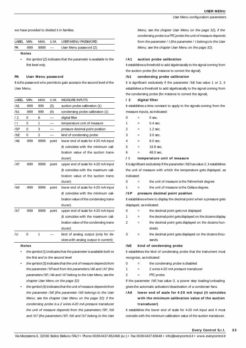
we have provided to divided it in families.
LABEL MIN. MAX. U.M. USER MENU PASSWORD
PA -999 9999 ---- User Menu password (2)
Notes
• the symbol (2) indicates that the parameter is available to the
first level only.
PA User Menu password
It is the password who permits to gain access to the second level of the
User Menu.
LABEL MIN. MAX. U.M. MEASURE INPUTS
/A1 -999 999 (3) suction probe calibration (1)
/b1 -999 999 (4) condensing probe calibration (1)
/ 2 0 6 ---- digital filter
/ t 0 1 ---- temperature unit of measure
/5P 0 3 ---- pressure decimal point position
/bE 0 2 ---- kind of condensing probe
/A6 -999 9999 point lower end of scale for 4-20 mA input
(it coincides with the minimum cali-
bration value of the suction trans-
ducer)
/A7 -999 9999 point upper end of scale for 4-20 mA input
(it coincides with the maximum cali-
bration value of the suction trans-
ducer)
/b6 -999 9999 point lower end of scale for 4-20 mA input
(it coincides with the minimum cali-
bration value of the condensing trans-
ducer)
/b7 -999 9999 point upper end of scale for 4-20 mA input
(it coincides with the maximum cali-
bration value of the condensing trans-
ducer)
/U 0 1 ---- kind of analog output (only for de-
vices with analog output in current)
Notes
• the symbol (1) indicates that the parameter is available both to
the first and to the second level
• the symbol (3) indicates that the unit of measure depends from
the parameter /5P and from the parameters /A6 and /A7 (the
parameters /5P, /A6 and /A7 belong to the User Menu; see the
chapter User Menu on the page 32)
• the symbol (4) indicates that the unit of measure depends from
the parameter /bE (the parameter /bE belongs to the User
Menu; see the chapter User Menu on the page 32): if the
condensing probe is a 2 wires 4-20 mA pressure transducer
the unit of measure depends from the parameters /5P, /b6
and /b7 (the parameters /5P, /b6 and /b7 belong to the User
Menu; see the chapter User Menu on the page 32), if the
condensing probe is a PTC probe the unit of measure depends
from the parameter / t (the parameter / t belongs to the User
Menu; see the chapter User Menu on the page 32).
/A1 suction probe calibration
It establishes a threshold to add algebraically to the signal coming from
the suction probe (for instance to correct the signal).
/b1 condensing probe calibration
It is significant exclusively if the parameter /bE has value 1 or 2, it
establishes a threshold to add algebraically to the signal coming from
the condensing probe (for instance to correct the signal).
/ 2 digital filter
It establishes a time constant to apply to the signals coming from the
measure inputs, as indicated:
0 = 0 sec.
1 = 0.4 sec.
2 = 1.2 sec.
3 = 3.0 sec.
4 = 8.0 sec.
5 = 19.8 sec.
6 = 48.0 sec.
/ t temperature unit of measure
It is significant exclusively if the parameter /bE has value 2, it establishes
the unit of measure with which the temperature gets displayed, as
indicated:
0 = the unit of measure is the Fahrenheit degree
1 = the unit of measure is the Celsius degree.
/5P pressure decimal point position
It establishes where to display the decimal point when a pressure gets
displayed, as indicated:
0 = the decimal point gets not displayed
1 = the decimal point gets displayed on the dozens display
2 = the decimal point gets displayed on the dozens hun-
dreds
3 = the decimal point gets displayed on the dozens thou-
sands.
/bE kind of condensing probe
It establishes the kind of condensing probe that the instrument must
recognize, as indicated:
0 = the condensing probe is disabled
1 = 2 wires 4-20 mA pressure transducer
2 = PTC probe.
If the parameter /bE has value 0, a power step loading/unloading
gives the automatic activation/deactivation of a condenser fans.
/A6 lower end of scale for 4-20 mA input (it coincides
with the minimum calibration value of the suction
transducer)
It establishes the lower end of scale for 4-20 mA input and it must
coincide with the minimum calibration value of the suction transducer.
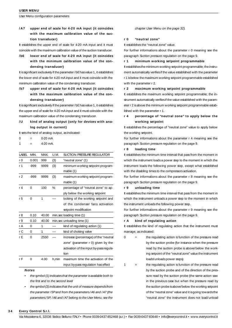
Every Control S.r.l.
Via Mezzaterra 6, 32036 Sedico Belluno ITALY • Phone 0039-0437-852468 (a.r.) • Fax 0039-0437-83648 • [email protected] • www.everycontrol.it
34
USER MENU
User Menu configuration parameters
/A7 upper end of scale for 4-20 mA input (it coincides
with the maximum calibration value of the suc-
tion transducer)
It establishes the upper end of scale for 4-20 mA input and it must
coincide with the maximum calibration value of the suction transducer.
/b6 lower end of scale for 4-20 mA input (it coincides
with the minimum calibration value of the con-
densing transducer)
It is significant exclusively if the parameter /bE has value 1, it establishes
the lower end of scale for 4-20 mA input and it must coincide with the
minimum calibration value of the condensing transducer.
/b7 upper end of scale for 4-20 mA input (it coincides
with the maximum calibration value of the con-
densing transducer)
It is significant exclusively if the parameter /bE has value 1, it establishes
the upper end of scale for 4-20 mA input and it must coincide with the
maximum calibration value of the condensing transducer.
/U kind of analog output (only for devices with ana-
log output in current)
It sets the kind of analog output, as indicated:
0 = 0-20 mA
1 = 4-20 mA.
LABEL MIN. MAX. U.M. SUCTION PRESSURE REGULATOR
r 0 0.001 999 (3) “neutral zone” (1)
r 1 -999 9999 (3) minimum working setpoint program-
mable (1)
r 2 -999 9999 (3) maximum working setpoint program-
mable (1)
r 4 0 100 % percentage of “neutral zone” to ap-
ply below the working setpoint
r 5 0 1 ---- locking of the working setpoint and
of the condenser fans activation
setpoint modification
r 8 0.10 40.00 min,sec loading time (1)
r 9 0.10 40.00 min,sec unloading time (1)
r A 0 1 ---- kind of regulating action (1)
r C 0 1 ---- kind of choking valve
r E 0 2550 ---- increase (percentage) of the “neutral
zone” (parameter r 0) given by the
activation of the input by-pass regula-
tion
r F 0 4.00 h,min maximum time the activation of the
input by-pass regulation has effect
Notes
• the symbol (1) indicates that the parameter is available both to
the first and to the second level
• the symbol (3) indicates that the unit of measure depends from
the parameter /5P and from the parameters /A6 and /A7 (the
parameters /5P, /A6 and /A7 belong to the User Menu; see the
chapter User Menu on the page 32).
r 0 “neutral zone”
It establishes the “neutral zone” value.
For further informations about the parameter r 0 meaning see the
paragraph Suction pressure regulation on the page 9.
r 1 minimum working setpoint programmable
It establishes the minimum working setpoint programmable; the instru-
ment automatically verifies if the value established with the parameter
r 1 is below the maximum working setpoint programmable established
with the parameter r 2.
r 2 maximum working setpoint programmable
It establishes the maximum working setpoint programmable; the in-
strument automatically verifies if the value established with the param-
eter r 2 is above the minimum working setpoint programmable estab-
lished with the parameter r 1.
r 4 percentage of “neutral zone” to apply below the
working setpoint
It establishes the percentage of “neutral zone” value to apply below
the working setpoint.
For further informations about the parameter r 4 meaning see the
paragraph Suction pressure regulation on the page 9.
r 8 loading time
It establishes the minimum time interval that pass from the moment in
which the instrument loads a power step to the moment in which the
instrument loads the following power step, except what established
with the disabling times to the compressors activation.
For further informations about the parameter r 8 meaning see the
paragraph Suction pressure regulation on the page 9.
r 9 unloading time
It establishes the minimum time interval that pass from the moment in
which the instrument unloads a power step to the moment in which
the instrument unloads the following power step.
For further informations about the parameter r 9 meaning see the
paragraph Suction pressure regulation on the page 9.
r A kind of regulating action
It establishes the kind of regulating action that the instrument must
manage, as indicated:
0 = the regulating action is function of the pressure read
by the suction probe (for instance when the pressure
read by the suction probe is above/below the work-
ing setpoint of the “neutral zone” value the instrument
loads/unloads power steps)
1 = the regulating action is function of the pressure read
by the suction probe and of the direction of the pres-
sure read by the suction probe (the same action saw
in the previous case but when the pressure read by
the suction probe is above/below the working setpoint
of the “neutral zone” value and it is going towards the
“neutral zone” the instrument does not load/unload

Every Control S.r.l.
Via Mezzaterra 6, 32036 Sedico Belluno ITALY • Phone 0039-0437-852468 (a.r.) • Fax 0039-0437-83648 • [email protected] • www.everycontrol.it
35
the previous activation
It establishes the time that disables the compressor activation from the
moment of the previous compressor activation.
For further informations about the parameter C 1 meaning see the
paragraph Compressors protection on the page 10.
C 2 disabling time to the compressor activation from
the previous deactivation
It establishes the time that disables the compressor activation from the
moment of the previous compressor deactivation.
For further informations about the parameter C 2 meaning see the
paragraph Compressors protection on the page 10.
C 6 number of power steps loaded during a suction
probe failure alarm
It establishes the number of power steps loaded during a suction probe
failure alarm, except what established with the parameters r 8 and r 9
and except what established with the disabling times to the compres-
sors activation (see the paragraph Alarms on the page 46).
C 7 number of running working hours of the power
step enough to request the unloading
It establishes the number of running working hours of a power step
enough to request the power step unloading (for instance, when the
conditions will permit it, the instrument will unload at first the power
step who will have the number of running working hours established
with the parameter C 7).
C H number of total working hours of the power step
enough to signal the request of service
It establishes the number of total working hours of a power step enough
to signal the request of service (see the paragraph Alarms on the page
46).
LABEL MIN. MAX. U.M. CONDENSER FANS REGULATOR
F 0 0.001 255 (4) proportional band (1)
F 1 F 6 F 7 (4) condenser fans activation setpoint (1)
F 6 -999 9999 (4) minimum condenser fans activation
setpoint programmable (1)
F 7 -999 9999 (4) maximum condenser fans activation
setpoint programmable (1)
F A 0 1 ---- condenser fans functioning
F d 0 1 ---- method used to compute which con-
denser fans activate/deactivate
F H 0 9999 hour number of total working hours of the
condenser fans enough to signal the
request of service (1)
Notes
• the symbol (1) indicates that the parameter is available both to
the first and to the second level
• the symbol (4) indicates that the unit of measure depends from
the parameter /bE (the parameter /bE belongs to the User
Menu; see the chapter User Menu on the page 32): if the
condensing probe is a 2 wires 4-20 mA pressure transducer
USER MENU
User Menu configuration parameters
power steps).
For further informations about the parameter r A meaning see the
paragraph Suction pressure regulation on the page 9.
r C kind of choking valve
It establishes the kind of choking valve that the instrument must man-
age, as indicated:
0 = NC choking valve
1 = NO choking valve.
For further informations about the parameter r C meaning see the
paragraph Suction pressure regulation on the page 9.
r E increase (percentage) of the “neutral zone”
(parameter r 0) given by the activation of the
input by-pass regulation
It sets the increase (percentage) of the “neutral zone” (parameter r 0)
when one activates the input for by-pass regulation (the instrument will
automatically increase the “neutral zone” applied over the working
setpoint; for example, set 100 % to double the value).
r F maximum time the activation of the input by-pass
regulation has effect
It sets the maximum time the activation of the input by-pass regulation
has effect; as soon as this time passes, the instrument will automatically
recover the normal operation, even is the input is activated; if the
parameter has value 0, the instrument will consider 99 min).
LABEL MIN. MAX. U.M. COMPRESSORS PROTECTION
C 0 0.00 40.00 min,sec disabling time to the compressor acti-
vation from the instrument start
C 1 0.00 40.00 min,sec disabling time to the compressor acti-
vation from the previous activation
C 2 0.00 40.00 min,sec disabling time to the compressor de-
activation from the previous activation
C 6 0 8 ---- number of power steps loaded dur-
ing a suction probe failure alarm
C 7 0 255 hour number of running working hours of
the power step enough to request
the unloading
C H 0 9999 hour number of total working hours of the
power step enough to signal the re-
quest of service (1)
Notes
• the symbol (1) indicates that the parameter is available both to
the first and to the second level.
C 0 disabling time to the compressor activation from
the instrument start
It establishes the time that disables the compressor activation from the
moment in which the instrument gets supplied.
For further informations about the parameter C 0 meaning see the
paragraph Compressors protection on the page 10.
C 1 disabling time to the compressor activation from

Every Control S.r.l.
Via Mezzaterra 6, 32036 Sedico Belluno ITALY • Phone 0039-0437-852468 (a.r.) • Fax 0039-0437-83648 • [email protected] • www.everycontrol.it
36
USER MENU
User Menu configuration parameters
the unit of measure depends from the parameters /5P, /b6
and /b7 (the parameters /5P, /b6 and /b7 belong to the User
Menu; see the chapter User Menu on the page 32), if the
condensing probe is a PTC probe the unit of measure depends
from the parameter / t (the parameter / t belongs to the User
Menu; see the chapter User Menu on the page 32).
F 0 proportional band
It is significant exclusively if the parameter /bE has value 1 or 2 and if
the parameter F A has value 0, it establishes the proportional band
width.
For further informations about the parameter F 0 meaning see the
paragraph Condensing quantity regulation on the page 12.
F 1 condenser fans activation setpoint
It has the same significance of the parameter F 1 of the Operator
Menu; see the chapter Operator Menu on the page 29.
F 6 minimum condenser fans activation setpoint pro-
grammable
It is significant exclusively if the parameter /bE has value 1 or 2 and if
the parameter F A has value 0, it establishes the minimum condenser
fans activation setpoint programmable; the instrument automatically
verifies if the value established with the parameter F 6 is below the
maximum condenser fans activation setpoint programmable estab-
lished with the parameter F 7.
F 7 maximum condenser fans activation setpoint pro-
grammable
It is significant exclusively if the parameter /bE has value 1 or 2 and if
the parameter F A has value 0, it establishes the maximum condenser
fans activation setpoint programmable; the instrument automatically
verifies if the value established with the parameter F 7 is above the
minimum condenser fans activation setpoint programmable established
with the parameter F 6.
F A condenser fans functioning
It establishes the condenser fans functioning that the instrument must
manage, as indicated:
0 = the condenser fans functioning is function of the quan-
tity read by the condensing probe (the instrument
automatically divides the proportional band established
with the parameter F 0 in equal fractions according
with the number of relay outputs associated to the
condenser fans, it activates the condenser fans with
sequence every time the quantity read by the con-
densing probe rises above the setpoint established
with the parameter F 1 of a fraction of proportional
band and it deactivates them with sequence when
the quantity read by the condensing probe falls below
the value to which the activation happened of a frac-
tion of proportional band)
1 = the condenser fans functioning is function of the power
steps loading/unloading (a power step loading/un-
loading gives the automatic activation/deactivation of
a condenser fans).
For further informations about the parameter F A meaning see the
paragraph Condensing quantity regulation on the page 12.
F d method used to compute which condenser fans
activate/deactivate
It establishes the method used by the instrument to compute which
condenser fans activate/deactivate, as indicated:
0 = the instrument activates the condenser fans with fixed
sequence and it deactivates them with the reversal
method (for instance if the users associated to the
outputs K5, K6, K7 and K8 are condenser fans, the
instrument activates them beginning from that associ-
ated to the output K5 and it deactivates them with the
reversal method)
1 = the instrument activates the condenser fans balancing
the total working hours and it deactivates them with
the reversal method (for instance the instrument acti-
vates the condenser fans with sequence beginning
from that with the lower number of total working
hours and it deactivates them with the reversal
method).
F H number of total working hours of the condenser
fans enough to signal the request of service
It establishes the number of total working hours of a condenser fans
enough to signal the request of service (see the paragraph Alarms on
the page 46).
LABEL MIN. MAX. U.M. DIGITAL INPUTS
i1P 0 1 ---- kind of contact of the user compres-
sor associated to the output K1 ... 8
locking digital inputs
i2P 0 1 ---- kind of contact of the user condenser
fans associated to the output K1 ... 8
locking digital inputs
i4P 0 1 ---- input configuration (freon level or by-
pass regulation)
i5P 0 1 ---- kind of contact of the input freon level/
by-pass regulation
i6P 0 1 ---- kind of contact of the condenser fans
safety digital input
i7P 0 1 ---- kind of contact of the upper condens-
ing quantity digital input
i8P 0 1 ---- kind of contact of the lower pressure
digital input
i1P kind of contact of the user compressor associated
to the output K1 ... 8 locking digital inputs
It is significant exclusively if the parameter tyP1 ... 8 has value CP, it
establishes the kind of contact of the user compressor associated to the

Every Control S.r.l.
Via Mezzaterra 6, 32036 Sedico Belluno ITALY • Phone 0039-0437-852468 (a.r.) • Fax 0039-0437-83648 • [email protected] • www.everycontrol.it
37
chapter User Menu on the page 32).
AA0 hysteresis (differential)
It is significant exclusively if the parameter AA4 has value 1 or 2, it
establishes the hysteresis (differential) relative to the setpoint estab-
lished with the parameter AA1.
For further informations about the parameter AA0 meaning see the
paragraph Lower pressure alarm on the page 13.
AA1 alarm setpoint
It is significant exclusively if the parameter AA4 has value 1 or 2, it
establishes the pressure below which the lower pressure alarm gets
activated according with the modality established with the parameter
AA4 and it is referred to the suction probe.
For further informations about the parameter AA1 meaning see the
paragraph Lower pressure alarm on the page 13.
AA4 kind of alarm
It establishes the kind of lower pressure alarm that the instrument must
manage, as indicated:
0 = the lower pressure alarm never gets activated
1 = absolute lower pressure alarm
2 = lower pressure alarm relative to the working setpoint.
For further informations about the parameter AA4 meaning see the
paragraph Lower pressure alarm on the page 13.
AA7 disabling time to the lower pressure alarm activa-
tion
It is significant exclusively if the parameter AA4 has value 1 or 2, it
establishes the time that disables a lower pressure alarm activation
from the moment in which the lower pressure alarm happens.
For further informations about the parameter AA7 meaning see the
paragraph Lower pressure alarm on the page 13.
AAn number of lower pressure alarms enough to give
the instrument locking
It establishes the number of lower pressure alarms enough to give the
instrument locking.
If the parameter AAn has value 0 the instrument locking never hap-
pens.
The increasing of the lower pressure alarms counter gets given also by
the lower pressure digital input activation.
For further informations about the parameter AAn meaning see the
paragraph Lower pressure alarm on the page 13.
LABEL MIN. MAX. U.M. UPPER PRESSURE ALARM
Ab0 0.001 255 (3) hysteresis (differential)
Ab1 -999 9999 (3) alarm setpoint
Ab4 0 2 --- kind of alarm
Ab7 0.00 4.15 min,sec disabling time to the upper pressure
alarm activation
Abn 0 15 ---- number of upper pressure alarms
enough to give the instrument lock-
ing
USER MENU
User Menu configuration parameters
output K1 ... 8 locking digital inputs, as indicated:
0 = NO contact
1 = NC contact.
The parameters tyP1 ... 8 belong to the Configurator Menu; see the
chapter Configurator Menu on the page 25.
For further informations about the parameter i1P meaning see the
paragraph Digital inputs on the page 13.
i2P kind of contact of the user condenser fans associ-
ated to the output K1 ... 8 locking digital inputs
It is significant exclusively if the parameter tyP1 ... 8 has value FAn, it
establishes the kind of contact of the user condenser fans associated to
the output K1 ... 8 locking digital inputs, as indicated:
0 = NO contact
1 = NC contact.
The parameters tyP1 ... 8 belong to the Configurator Menu; see the
chapter Configurator Menu on the page 25.
For further informations about the parameter i2P meaning see the
paragraph Digital inputs on the page 13.
i4P input configuration (freon level or by-pass regula-
tion)
It establishes the configuration of the input, as indicated:
0 = freon level
1 = by-pass regulation.
i5P kind of contact of the input freon level/by-pass
regulation
It establishes the kind of contact of the input, as indicated:
0 = NO contact
1 = NC contact.
i6P kind of contact of the condenser fans safety dig-
ital input
It has the same significance of the parameter i5P
i7P kind of contact of the upper condensing quantity
digital input
It has the same significance of the parameter i5P
i8P kind of contact of the lower pressure digital input
It has the same significance of the parameter i5P
LABEL MIN. MAX. U.M. LOWER PRESSURE ALARM
AA0 0.001 255 (3) hysteresis (differential)
AA1 -999 9999 (3) alarm setpoint
AA4 0 2 --- kind of alarm
AA7 0.00 4.15 min,sec disabling time to the lower pressure
alarm activation
AAn 0 15 ---- number of lower pressure alarms
enough to give the instrument lock-
ing
Notes
• the symbol (3) indicates that the unit of measure depends from
the parameter /5P and from the parameters /A6 and /A7 (the
parameters /5P, /A6 and /A7 belong to the User Menu; see the

Every Control S.r.l.
Via Mezzaterra 6, 32036 Sedico Belluno ITALY • Phone 0039-0437-852468 (a.r.) • Fax 0039-0437-83648 • [email protected] • www.everycontrol.it
38
ACn 0 15 ---- number of upper condensing quan-
tity alarms enough to give the instru-
ment locking
Notes
• the symbol (4) indicates that the unit of measure depends from
the parameter /bE (the parameter /bE belongs to the User
Menu; see the chapter User Menu on the page 32): if the
condensing probe is a 2 wires 4-20 mA pressure transducer
the unit of measure depends from the parameters /5P, /b6
and /b7 (the parameters /5P, /b6 and /b7 belong to the User
Menu; see the chapter User Menu on the page 32), if the
condensing probe is a PTC probe the unit of measure depends
from the parameter / t (the parameter / t belongs to the User
Menu; see the chapter User Menu on the page 32).
AC0 hysteresis (differential)
It is significant exclusively if the parameter /bE has value 1 or 2 and if
the parameter AC4 has value 1 or 2, it establishes the hysteresis (differ-
ential) relative to the setpoint established with the parameter AC1.
For further informations about the parameter AC0 meaning see the
paragraph Upper condensing quantity alarm on the page 15.
AC1 alarm setpoint
It is significant exclusively if the parameter /bE has value 1 or 2 and if
the parameter AC4 has value 1 or 2, it establishes the condensing
quantity value above which the upper condensing quantity alarm gets
activated according with the modality established with the parameter
AC4 and it is referred to the condensing probe.
For further informations about the parameter AC1 meaning see the
paragraph Upper condensing quantity alarm on the page 15.
AC4 kind of alarm
It is significant exclusively if the parameter /bE has value 1 or 2, it
establishes the kind of upper condensing quantity alarm that the instru-
ment must manage, as indicated:
0 = the upper condensing quantity alarm never gets acti-
vated
1 = absolute upper condensing quantity alarm
2 = upper condensing quantity alarm relative to the
setpoint established with the parameter F 1.
For further informations about the parameter AC4 meaning see the
paragraph Upper condensing quantity alarm on the page 15.
AC7 disabling time to the upper condensing quantity
alarm activation
It is significant exclusively if the parameter /bE has value 1 or 2 and if
the parameter AC4 has value 1 or 2, it establishes the time that disables
an upper condensing quantity alarm activation from the moment in
which the upper condensing quantity alarm happens.
For further informations about the parameter AC7 meaning see the
paragraph Upper condensing quantity alarm on the page 15.
ACn number of upper condensing quantity alarms
enough to give the instrument locking
USER MENU
User Menu configuration parameters
Notes
• the symbol (3) indicates that the unit of measure depends from
the parameter /5P and from the parameters /A6 and /A7 (the
parameters /5P, /A6 and /A7 belong to the User Menu; see the
chapter User Menu on the page 32).
Ab0 hysteresis (differential)
It is significant exclusively if the parameter Ab4 has value 1 or 2, it
establishes the hysteresis (differential) relative to the setpoint estab-
lished with the parameter Ab1.
For further informations about the parameter Ab0 meaning see the
paragraph Upper pressure alarm on the page 15.
Ab1 alarm setpoint
It is significant exclusively if the parameter Ab4 has value 1 or 2, it
establishes the pressure above which the upper pressure alarm gets
activated according with the modality established with the parameter
Ab4 and it is referred to the suction probe.
For further informations about the parameter Ab1 meaning see the
paragraph Upper pressure alarm on the page 15.
Ab4 kind of alarm
It establishes the kind of upper pressure alarm that the instrument must
manage, as indicated:
0 = the upper pressure alarm never gets activated
1 = absolute upper pressure alarm
2 = upper pressure alarm relative to the working setpoint.
For further informations about the parameter Ab4 meaning see the
paragraph Upper pressure alarm on the page 15.
Ab7 disabling time to the upper pressure alarm activa-
tion
It is significant exclusively if the parameter Ab4 has value 1 or 2, it
establishes the time that disables an upper pressure alarm activation
from the moment in which the upper pressure alarm happens.
For further informations about the parameter Ab7 meaning see the
paragraph Upper pressure alarm on the page 15.
Abn number of upper pressure alarms enough to give
the instrument locking
It establishes the number of upper pressure alarms enough to give the
instrument locking.
If the parameter Abn has value 0 the instrument locking never hap-
pens.
For further informations about the parameter Abn meaning see the
paragraph Upper pressure alarm on the page 15.
LABEL MIN. MAX. U.M. UPPER CONDENSING QUANTITY
ALARM
AC0 0.001 255 (4) hysteresis (differential)
AC1 -999 9999 (4) alarm setpoint
AC4 0 2 --- kind of alarm
AC7 0.00 4.15 min,sec disabling time to the upper condens-
ing quantity alarm activation
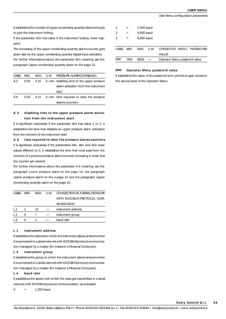
Every Control S.r.l.
Via Mezzaterra 6, 32036 Sedico Belluno ITALY • Phone 0039-0437-852468 (a.r.) • Fax 0039-0437-83648 • [email protected] • www.everycontrol.it
39
USER MENU
User Menu configuration parameters
It establishes the number of upper condensing quantity alarms enough
to give the instrument locking.
If the parameter ACn has value 0 the instrument locking never hap-
pens.
The increasing of the upper condensing quantity alarms counter gets
given also by the upper condensing quantity digital input activation.
For further informations about the parameter ACn meaning see the
paragraph Upper condensing quantity alarm on the page 15.
LABEL MIN. MAX. U.M. PRESSURE ALARMS DISABLING
A 3 0.00 4.15 h.,min disabling time to the upper pressure
alarm activation from the instrument
start
A 6 0.00 4.15 h.,min time required to clear the pressure
alarms counters
A 3 disabling time to the upper pressure alarm activa-
tion from the instrument start
It is significant exclusively if the parameter Ab4 has value 1 or 2, it
establishes the time that disables an upper pressure alarm activation
from the moment of the instrument start.
A 6 time required to clear the pressure alarms counters
It is significant exclusively if the parameters AAn, Abn and ACn have
values different to 0, it establishes the time that must pass from the
moment of a previous pressure alarms counter increasing in order that
the counter get cleared.
For further informations about the parameter A 6 meaning see the
paragraph Lower pressure alarm on the page 14, the paragraph
Upper pressure alarm on the a page 15 and the paragraph Upper
condensing quantity alarm on the page 15.
LABEL MIN. MAX. U.M. CONNECTION IN A SERIAL NETWORK
WITH EVCOBUS PROTOCOL COM-
MUNICATION
L 1 1 15 ---- instrument address
L 2 0 7 ---- instrument group
L 4 0 3 ---- baud rate
L 1 instrument address
It establishes the address to which the instrument (slave) answers when
it is connected to a serial network with EVCOBUS protocol communica-
tion managed by a master (for instance a Personal Computer).
L 2 instrument group
It establishes the group to which the instrument (slave) answers when
it is connected to a serial network with EVCOBUS protocol communica-
tion managed by a master (for instance a Personal Computer).
L 4 baud rate
It establishes the speed with which the data get transmitted in a serial
network with EVCOBUS protocol communication, as indicated:
0 = 1,200 baud
1 = 2,400 baud
2 = 4,800 baud
3 = 9,600 baud.
LABEL MIN. MAX. U.M. OPERATOR MENU PASSWORD
VALUE
PPP -999 9999 ---- Operator Menu password value
PPP Operator Menu password value
It establishes the value of the password who permits to gain access to
the second level of the Operator Menu.

Every Control S.r.l.
Via Mezzaterra 6, 32036 Sedico Belluno ITALY • Phone 0039-0437-852468 (a.r.) • Fax 0039-0437-83648 • [email protected] • www.everycontrol.it
40
CONFIGURATION PARAMETERS AND DEFAULT VALUES SUMMARIZING TABLE
Configurator Menu configuration parameters - Operator Menu configuration parameters
CONFIGURATOR MENU CONFIGURATION PARAMETERS
LABEL MIN. MAX. U.M. DEF. USERS TOTAL WORKING HOURS COUNTER
Hr 1 ---- ---- hour ---- total working hours of the user associated to the output K1 (1)
Hr 2 ---- ---- hour ---- total working hours of the user associated to the output K2 (1)
Hr 3 ---- ---- hour ---- total working hours of the user associated to the output K3 (1)
Hr 4 ---- ---- hour ---- total working hours of the user associated to the output K4 (1)
Hr 5 ---- ---- hour ---- total working hours of the user associated to the output K5 (1)
Hr 6 ---- ---- hour ---- total working hours of the user associated to the output K6 (1)
Hr 7 ---- ---- hour ---- total working hours of the user associated to the output K7 (1)
Hr 8 ---- ---- hour ---- total working hours of the user associated to the output K8 (1)
LABEL MIN. MAX. U.M. DEF. OPERATOR MENU PASSWORD
OPEr -999 9999 ---- 0 Operator Menu password (2)
LABEL MIN. MAX. U.M. DEF. USER-RELAY OUTPUT CONFIGURATION
tyP1 undF Cho ---- CP user to associate to the output K1
tyP2 undF Cho ---- CP user to associate to the output K2
tyP3 undF Cho ---- CP user to associate to the output K3
tyP4 undF Cho ---- CP user to associate to the output K4
tyP5 undF Cho ---- FAn user to associate to the output K5
tyP6 undF Cho ---- FAn user to associate to the output K6
tyP7 undF Cho ---- FAn user to associate to the output K7
tyP8 undF Cho ---- FAn user to associate to the output K8
LABEL MIN. MAX. U.M. DEF. COMPRESSORS POWER MANAGER
Po 1 1 15 ---- 10 power of the compressor associated to the output K1
Po 2 1 15 ---- 10 power of the compressor associated to the output K2
Po 3 1 15 ---- 10 power of the compressor associated to the output K3
Po 4 1 15 ---- 10 power of the compressor associated to the output K4
Po 5 1 15 ---- ---- power of the compressor associated to the output K5
Po 6 1 15 ---- ---- power of the compressor associated to the output K6
Po 7 1 15 ---- ---- power of the compressor associated to the output K7
Po 8 1 15 ---- ---- power of the compressor associated to the output K8
Notes
• the symbol (1) indicates that the parameter is available both to the first and to the second level
• the symbol (2) indicates that the parameter is available to the first level only.
OPERATOR MENU CONFIGURATION PARAMETERS
LABEL MIN. MAX. U.M. DEF. USERS STATUS
St 1 OFF On ---- ---- status of the user associated to the output K1
St 2 OFF On ---- ---- status of the user associated to the output K2
St 3 OFF On ---- ---- status of the user associated to the output K3
St 4 OFF On ---- ---- status of the user associated to the output K4
St 5 OFF On ---- ---- status of the user associated to the output K5
St 6 OFF On ---- ---- status of the user associated to the output K6
St 7 OFF On ---- ---- status of the user associated to the output K7
St 8 OFF On ---- ---- status of the user associated to the output K8
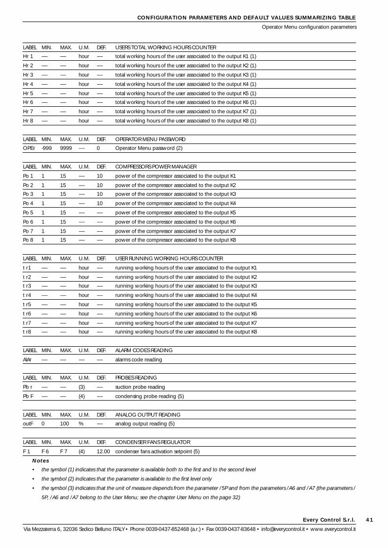
Every Control S.r.l.
Via Mezzaterra 6, 32036 Sedico Belluno ITALY • Phone 0039-0437-852468 (a.r.) • Fax 0039-0437-83648 • [email protected] • www.everycontrol.it
41
LABEL MIN. MAX. U.M. DEF. USERS TOTAL WORKING HOURS COUNTER
Hr 1 ---- ---- hour ---- total working hours of the user associated to the output K1 (1)
Hr 2 ---- ---- hour ---- total working hours of the user associated to the output K2 (1)
Hr 3 ---- ---- hour ---- total working hours of the user associated to the output K3 (1)
Hr 4 ---- ---- hour ---- total working hours of the user associated to the output K4 (1)
Hr 5 ---- ---- hour ---- total working hours of the user associated to the output K5 (1)
Hr 6 ---- ---- hour ---- total working hours of the user associated to the output K6 (1)
Hr 7 ---- ---- hour ---- total working hours of the user associated to the output K7 (1)
Hr 8 ---- ---- hour ---- total working hours of the user associated to the output K8 (1)
LABEL MIN. MAX. U.M. DEF. OPERATOR MENU PASSWORD
OPEr -999 9999 ---- 0 Operator Menu password (2)
LABEL MIN. MAX. U.M. DEF. COMPRESSORS POWER MANAGER
Po 1 1 15 ---- 10 power of the compressor associated to the output K1
Po 2 1 15 ---- 10 power of the compressor associated to the output K2
Po 3 1 15 ---- 10 power of the compressor associated to the output K3
Po 4 1 15 ---- 10 power of the compressor associated to the output K4
Po 5 1 15 ---- ---- power of the compressor associated to the output K5
Po 6 1 15 ---- ---- power of the compressor associated to the output K6
Po 7 1 15 ---- ---- power of the compressor associated to the output K7
Po 8 1 15 ---- ---- power of the compressor associated to the output K8
LABEL MIN. MAX. U.M. DEF. USER RUNNING WORKING HOURS COUNTER
t r1 ---- ---- hour ---- running working hours of the user associated to the output K1
t r2 ---- ---- hour ---- running working hours of the user associated to the output K2
t r3 ---- ---- hour ---- running working hours of the user associated to the output K3
t r4 ---- ---- hour ---- running working hours of the user associated to the output K4
t r5 ---- ---- hour ---- running working hours of the user associated to the output K5
t r6 ---- ---- hour ---- running working hours of the user associated to the output K6
t r7 ---- ---- hour ---- running working hours of the user associated to the output K7
t r8 ---- ---- hour ---- running working hours of the user associated to the output K8
LABEL MIN. MAX. U.M. DEF. ALARM CODES READING
AlAr ---- ---- ---- ---- alarms code reading
LABEL MIN. MAX. U.M. DEF. PROBES READING
Pb r ---- ---- (3) ---- suction probe reading
Pb F ---- ---- (4) ---- condensing probe reading (5)
LABEL MIN. MAX. U.M. DEF. ANALOG OUTPUT READING
outF 0 100 % ---- analog output reading (5)
LABEL MIN. MAX. U.M. DEF. CONDENSER FANS REGULATOR
F 1 F 6 F 7 (4) 12.00 condenser fans activation setpoint (5)
Notes
• the symbol (1) indicates that the parameter is available both to the first and to the second level
• the symbol (2) indicates that the parameter is available to the first level only
• the symbol (3) indicates that the unit of measure depends from the parameter /5P and from the parameters /A6 and /A7 (the parameters /
5P, /A6 and /A7 belong to the User Menu; see the chapter User Menu on the page 32)
CONFIGURATION PARAMETERS AND DEFAULT VALUES SUMMARIZING TABLE
Operator Menu configuration parameters

Every Control S.r.l.
Via Mezzaterra 6, 32036 Sedico Belluno ITALY • Phone 0039-0437-852468 (a.r.) • Fax 0039-0437-83648 • [email protected] • www.everycontrol.it
42
CONFIGURATION PARAMETERS AND DEFAULT VALUES SUMMARIZING TABLE
Operator Menu configuration parameters - User Menu configuration parameters
• the symbol (4) indicates that the unit of measure depends from the parameter /bE (the parameter /bE belongs to the User Menu; see the
chapter User Menu on the page 32): if the condensing probe is a 2 wires 4-20 mA pressure transducer the unit of measure depends from the
parameters /5P, /b6 and /b7 (the parameters /5P, /b6 and /b7 belong to the User Menu; see the chapter User Menu on the page 32), if the
condensing probe is a PTC probe the unit of measure depends from the parameter / t (the parameter / t belongs to the User Menu; see the
chapter User Menu on the page 32)
• the symbol (5) indicates that during the status ON the parameter is available both to the first and to the second level.
USER MENU CONFIGURATION PARAMETERS
LABEL MIN. MAX. U.M. DEF. USER MENU PASSWORD
PA -999 9999 ---- 0 User Menu password (2)
LABEL MIN. MAX. U.M. DEF. MEASURE INPUTS
/A1 -999 999 (3) 0.00 suction probe calibration (1)
/b1 -999 999 (4) 0.00 condensing probe calibration (1)
/ 2 0 6 ---- 1 digital filter
/ t 0 1 ---- 1 temperature unit of measure
/5P 0 3 ---- 2 pressure decimal point position
/bE 0 2 ---- 1 kind of condensing probe
/A6 -999 9999 point -0.50 lower end of scale for 4-20 mA input (it coincides with the minimum calibration value of the suction trans-
ducer)
/A7 -999 9999 point 7.00 upper end of scale for 4-20 mA input (it coincides with the maximum calibration value of the suction
transducer)
/b6 -999 9999 point 0.00 lower end of scale for 4-20 mA input (it coincides with the minimum calibration value of the condensing
transducer)
/b7 -999 9999 point 30.00 upper end of scale for 4-20 mA input (it coincides with the maximum calibration value of the condensing
transducer)
/U 0 1 ---- 0 kind of analog output (only for devices with analog output in current)
LABEL MIN. MAX. U.M. DEF. SUCTION PRESSURE REGULATOR
r 0 0.001 999 (3) 0.20 “neutral zone” (1)
r 1 -999 9999 (3) 0.00 minimum working setpoint programmable (1)
r 2 -999 9999 (3) 7.00 maximum working setpoint programmable (1)
r 4 0 100 % 100 percentage of “neutral zone” to apply below the working setpoint
r 5 0 1 ---- 0 locking of the working setpoint and of the condenser fans activation setpoint modification
r 8 0.10 40.00 min,sec 0.10 loading time (1)
r 9 0.10 40.00 min,sec 0.10 unloading time (1)
r A 0 1 ---- 1 kind of regulating action (1)
r C 0 1 ---- 0 kind of choking valve
r E 0 2550 ---- 100 increase (percentage) of the “neutral zone” (parameter r 0) given by the activation of the input by-pass
regulation
r F 0 4.00 h,min 0.10 maximum time the activation of the input by-pass regulation has effect
LABEL MIN. MAX. U.M. DEF. COMPRESSORS PROTECTION
C 0 0.00 40.00 min,sec 0.10 disabling time to the compressor activation from the instrument start
C 1 0.00 40.00 min,sec 0.00 disabling time to the compressor activation from the previous activation
C 2 0.00 40.00 min,sec 0.10 disabling time to the compressor activation from the previous deactivation
C 6 0 8 ---- 0 number of power steps loaded during a suction probe failure alarm
C 7 0 255 hour 0 number of running working hours of the power step enough to request the unloading
C H 0 9999 hour 1000 number of total working hours of the power step enough to signal the request of service (1)

Every Control S.r.l.
Via Mezzaterra 6, 32036 Sedico Belluno ITALY • Phone 0039-0437-852468 (a.r.) • Fax 0039-0437-83648 • [email protected] • www.everycontrol.it
43
CONFIGURATION PARAMETERS AND DEFAULT VALUES SUMMARIZING TABLE
User Menu configuration parameters
LABEL MIN. MAX. U.M. DEF. CONDENSER FANS REGULATOR
F 0 0.001 255 (4) 2.00 proportional band (1)
F 1 F 6 F 7 (4) 12.00 condenser fans activation setpoint (1)
F 6 -999 9999 (4) 0.00 minimum condenser fans activation setpoint programmable (1)
F 7 -999 9999 (4) 30.00 maximum condenser fans activation setpoint programmable (1)
F A 0 1 ---- 0 condenser fans functioning
F d 0 1 ---- 0 method used to compute which condenser fans activate/deactivate
F H 0 9999 hour 9999 number of total working hours of the condenser fans enough to signal the request of service (1)
LABEL MIN. MAX. U.M. DEF. DIGITAL INPUTS
i1P 0 1 ---- 0 kind of contact of the user compressor associated to the output K1 ... 8 locking digital inputs
i2P 0 1 ---- 0 kind of contact of the user condenser fans associated to the output K1 ... 8 locking digital inputs
i4P 0 1 ---- 0 input configuration (freon level or by-pass regulation)
i5P 0 1 ---- 0 kind of contact of the input freon level/by-pass regulation
i6P 0 1 ---- 0 kind of contact of the condenser fans safety digital input
i7P 0 1 ---- 0 kind of contact of the upper condensing quantity digital input
i8P 0 1 ---- 0 kind of contact of the lower pressure digital input
LABEL MIN. MAX. U.M. DEF. LOWER PRESSURE ALARM
AA0 0.001 255 (3) 0.01 hysteresis (differential)
AA1 -999 9999 (3) 0.00 alarm setpoint
AA4 0 2 ---- 0 kind of alarm
AA7 0.00 4.15 min,sec 0.00 disabling time to the lower pressure alarm activation
AAn 0 15 ---- 0 number of lower pressure alarms enough to give the instrument locking
LABEL MIN. MAX. U.M. DEF. UPPER PRESSURE ALARM
Ab0 0.001 255 (3) 0.01 hysteresis (differential)
Ab1 -999 9999 (3) 0.00 alarm setpoint
Ab4 0 2 ---- 0 kind of alarm
Ab7 0.00 4.15 min,sec 0.00 disabling time to the upper pressure alarm activation
Abn 0 15 ---- 0 number of upper pressure alarms enough to give the instrument locking
LABEL MIN. MAX. U.M. DEF. UPPER CONDENSING QUANTITY ALARM
AC0 0.001 255 (3) 0.01 hysteresis (differential)
AC1 -999 9999 (3) 0.00 alarm setpoint
AC4 0 2 ---- 0 kind of alarm
AC7 0.00 4.15 min,sec 0.00 disabling time to the upper condensing quantity alarm activation
ACn 0 15 ---- 0 number of upper condensing quantity alarms enough to give the instrument locking
LABEL MIN. MAX. U.M. DEF. PRESSURE ALARMS DISABLING
A 3 0.00 4.15 h,min 0.00 disabling time to the upper pressure alarm activation from the instrument start
A 6 0.00 4.15 h,min 0.00 time required to clear the pressure alarms counters
LABEL MIN. MAX. U.M. DEF. CONNECTION IN A SERIAL NETWORK WITH EVCOBUS PROTOCOL COMMUNICATION
L 1 1 15 ---- 1 instrument address
L 2 0 7 ---- 0 instrument group
L 4 0 3 ---- 1 baud rate
LABEL MIN. MAX. U.M. DEF. OPERATOR MENU PASSWORD VALUE

Every Control S.r.l.
Via Mezzaterra 6, 32036 Sedico Belluno ITALY • Phone 0039-0437-852468 (a.r.) • Fax 0039-0437-83648 • [email protected] • www.everycontrol.it
44
CONFIGURATION PARAMETERS AND DEFAULT VALUES SUMMARIZING TABLE
User Menu configuration parameters
PPP -999 9999 ---- -19 Operator Menu password value
Notes
• the symbol (1) indicates that the parameter is available both to the first and to the second level
• the symbol (2) indicates that the parameter is available to the first level only
• the symbol (3) indicates that the unit of measure depends from the parameter /5P and from the parameters /A6 and /A7 (the parameters /
5P, /A6 and /A7 belong to the User Menu; see the chapter User Menu on the page 32)
• the symbol (4) indicates that the unit of measure depends from the parameter /bE (the parameter /bE belongs to the User Menu; see the
chapter User Menu on the page 32): if the condensing probe is a 2 wires 4-20 mA pressure transducer the unit of measure depends from the
parameters /5P, /b6 and /b7 (the parameters /5P, /b6 and /b7 belong to the User Menu; see the chapter User Menu on the page 32), if the
condensing probe is a PTC probe the unit of measure depends from the parameter / t (the parameter / t belongs to the User Menu; see the
chapter User Menu on the page 32)
• the symbol (5) indicates that during the status ON the parameter is available both to the first and to the second level.

Every Control S.r.l.
Via Mezzaterra 6, 32036 Sedico Belluno ITALY • Phone 0039-0437-852468 (a.r.) • Fax 0039-0437-83648 • [email protected] • www.everycontrol.it
45
If the compressor/choking valve associated to the output K1 ... 8 LED is
turned on it means that the user associated to the output K1 ... 8 is a
compressor or a choking valve.
If the compressor/choking valve associated to the output K1 ... 8 LED
flashes it means that a count of a disabling time to the compressor
associated to the output K1 ... 8 activation is running; see the param-
eters C 0, C 1 and C 2 (the parameters C 0, C 1 and C 2 belong to the
User Menu; see the chapter User Menu on the page 32).
If the condenser fans associated to the output K1 ... 8 LED is turned on
it means that the user associated to the output K1 ... 8 is a condenser
fans.
If the power step or condenser fans associated to the output K1 ... 8
status LED is turned on it means that the power step associated to the
output K1 ... 8 is loaded or that the condenser fans associated to the
output K1 ... 8 is activated.
SIGNALS AND ALARMS
Signals
SIGNALS
If the minutes LED is turned on it means that the unit of measure of the
displayed quantity is the minute.
If the hours LED is turned on it means that the unit of measure of the
displayed quantity is the hour.
If the bar LED is turned on it means that the unit of measure of the
displayed quantity is the bar or that the displayed quantity is a pressure.
If the Celsius degree LED is turned on it means that the unit of measure
of the displayed quantity is the Celsius degree or that the displayed
quantity is a temperature.
If the data LED flashes it means that a data transmission in a serial
network with EVCOBUS protocol communication managed by a mas-
ter (for instance a Personal Computer) is running

Every Control S.r.l.
Via Mezzaterra 6, 32036 Sedico Belluno ITALY • Phone 0039-0437-852468 (a.r.) • Fax 0039-0437-83648 • [email protected] • www.everycontrol.it
46
If the ON STAND-BY LED is lit it means that the instrument is in the status
STAND-BY; if it flashes , the input by-pass regulation will be active.
If the menu LED is turned on it means that a configurator or Operator
Menu configuration parameters setting procedure is running.
ALARMS
If the instrument displays the indication “E2” flashing and the buzzer
utters an intermittent beep (corrupted memory data alarm) it
means that
• there is a corruption of the configuration data in the memory
(disconnect and connect again the instrument to the local power
supply: if when the power supply recovers the alarm does not
disappear the instrument must be replaced).
During this alarm the access to the setting procedures is refused, the
outputs K1 ... 8 get forced to the status OFF, the output Al1 gets
deactivated and the output Al1 gets activated.
If the instrument displays the indication “AL1r” for four seconds (or the
indication “AL1r” flashing for four seconds), the buzzer utters an inter-
mittent beep and the alarm LED flashes (instrument locking) it
SIGNALS AND ALARMS
Signals - Alarms
means that
• there was a number of lower pressure alarms enough to give
the instrument locking and, if the indication is flashing, that the
pressure read by the suction probe is below the alarm setpoint
again (turn off and turn on again the instrument, see the
parameters AA0, AA1, AA4, AAn and i8P: the parameters AA0,
AA1, AA4, AAn and i8P belong to the User Menu; see the
chapter User Menu on the page 32).
During this alarm all power steps get unloaded, the output Al1 gets
deactivated and the output Al1 gets activated.
If the instrument displays the indication “E LP” flashing for four sec-
onds, the buzzer utters an intermittent beep and the alarm LED flashes
(instrument locking) it means that
• there was a number of lower pressure digital input alarms
enough to give the instrument locking (turn off and turn on
again the instrument, see the parameters AA0, AA1, AA4, AAn
and i8P: the parameters AA0, AA1, AA4, AAn and i8P belong to
the User Menu; see the chapter User Menu on the page 32).
During this alarm all power steps get unloaded, the output Al1 gets
deactivated and the output Al1 gets activated.
If the instrument displays the indication “AL2r” for four seconds (or the
indication “AL2r” flashing for four seconds), the buzzer utters an inter-
mittent beep and the alarm LED flashes (instrument locking) it
means that
• there was a number of upper pressure alarms enough to give
the instrument locking and, if the indication is flashing, that the
pressure read by the suction probe is above the alarm setpoint
again (turn off and turn on again the instrument, see the
parameters Ab0, Ab1, Ab4 and Abn: the parameters Ab0, Ab1,
Ab4 and Abn belong to the User Menu; see the chapter User
Menu on the page 32).
During this alarm the output Al1 gets deactivated and the output Al1
gets activated.
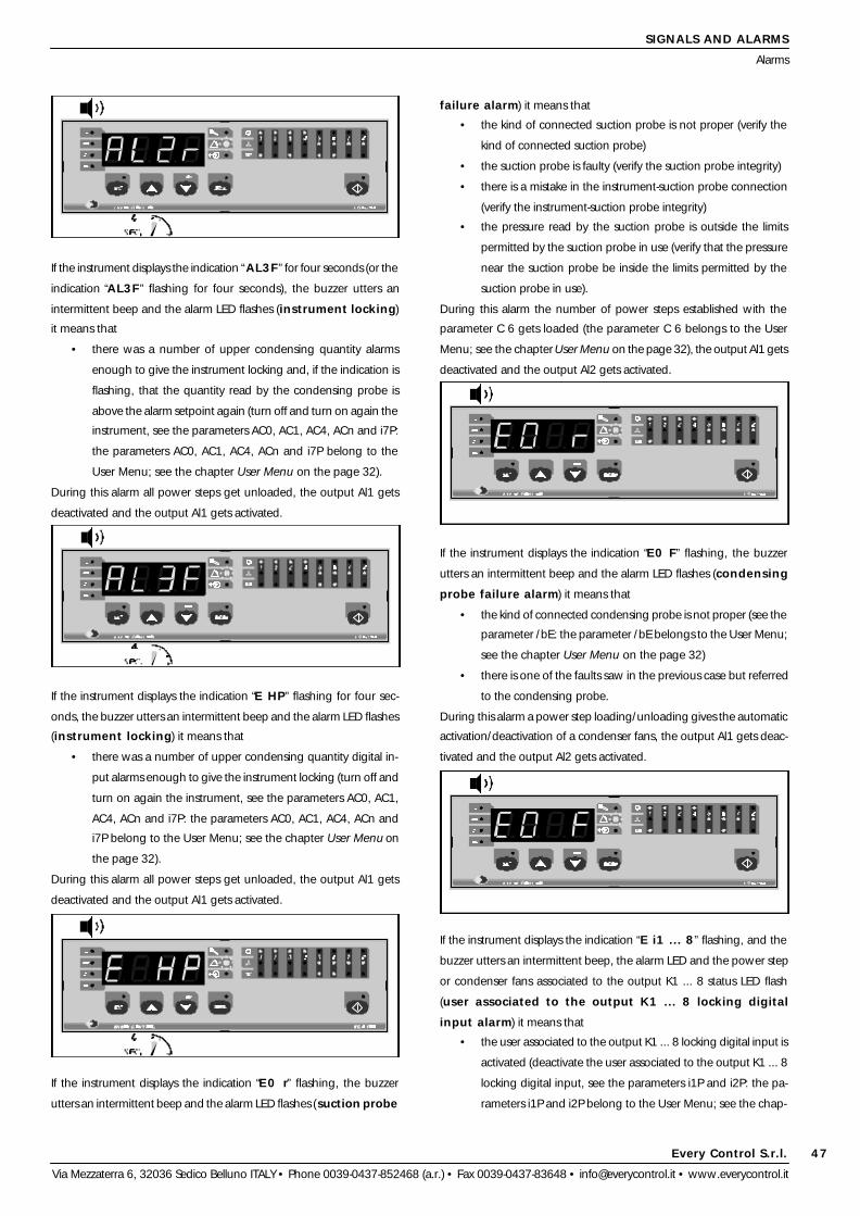
Every Control S.r.l.
Via Mezzaterra 6, 32036 Sedico Belluno ITALY • Phone 0039-0437-852468 (a.r.) • Fax 0039-0437-83648 • [email protected] • www.everycontrol.it
47
SIGNALS AND ALARMS
Alarms
If the instrument displays the indication “AL3F” for four seconds (or the
indication “AL3F” flashing for four seconds), the buzzer utters an
intermittent beep and the alarm LED flashes (instrument locking)
it means that
• there was a number of upper condensing quantity alarms
enough to give the instrument locking and, if the indication is
flashing, that the quantity read by the condensing probe is
above the alarm setpoint again (turn off and turn on again the
instrument, see the parameters AC0, AC1, AC4, ACn and i7P:
the parameters AC0, AC1, AC4, ACn and i7P belong to the
User Menu; see the chapter User Menu on the page 32).
During this alarm all power steps get unloaded, the output Al1 gets
deactivated and the output Al1 gets activated.
If the instrument displays the indication “E HP” flashing for four sec-
onds, the buzzer utters an intermittent beep and the alarm LED flashes
(instrument locking) it means that
• there was a number of upper condensing quantity digital in-
put alarms enough to give the instrument locking (turn off and
turn on again the instrument, see the parameters AC0, AC1,
AC4, ACn and i7P: the parameters AC0, AC1, AC4, ACn and
i7P belong to the User Menu; see the chapter User Menu on
the page 32).
During this alarm all power steps get unloaded, the output Al1 gets
deactivated and the output Al1 gets activated.
If the instrument displays the indication “E0 r” flashing, the buzzer
utters an intermittent beep and the alarm LED flashes (suction probe
failure alarm) it means that
• the kind of connected suction probe is not proper (verify the
kind of connected suction probe)
• the suction probe is faulty (verify the suction probe integrity)
• there is a mistake in the instrument-suction probe connection
(verify the instrument-suction probe integrity)
• the pressure read by the suction probe is outside the limits
permitted by the suction probe in use (verify that the pressure
near the suction probe be inside the limits permitted by the
suction probe in use).
During this alarm the number of power steps established with the
parameter C 6 gets loaded (the parameter C 6 belongs to the User
Menu; see the chapter User Menu on the page 32), the output Al1 gets
deactivated and the output Al2 gets activated.
If the instrument displays the indication “E0 F” flashing, the buzzer
utters an intermittent beep and the alarm LED flashes (condensing
probe failure alarm) it means that
• the kind of connected condensing probe is not proper (see the
parameter /bE: the parameter /bE belongs to the User Menu;
see the chapter User Menu on the page 32)
• there is one of the faults saw in the previous case but referred
to the condensing probe.
During this alarm a power step loading/unloading gives the automatic
activation/deactivation of a condenser fans, the output Al1 gets deac-
tivated and the output Al2 gets activated.
If the instrument displays the indication “E i1 ... 8” flashing, and the
buzzer utters an intermittent beep, the alarm LED and the power step
or condenser fans associated to the output K1 ... 8 status LED flash
(user associated to the output K1 ... 8 locking digital
input alarm) it means that
• the user associated to the output K1 ... 8 locking digital input is
activated (deactivate the user associated to the output K1 ... 8
locking digital input, see the parameters i1P and i2P: the pa-
rameters i1P and i2P belong to the User Menu; see the chap-

Every Control S.r.l.
Via Mezzaterra 6, 32036 Sedico Belluno ITALY • Phone 0039-0437-852468 (a.r.) • Fax 0039-0437-83648 • [email protected] • www.everycontrol.it
48
SIGNALS AND ALARMS
Alarms
ter User Menu on the page 32).
During this alarm the user associated to the output K1 ... 8 gets forced
to the status OFF and the output Al2 gets activated.
If the instrument displays the indication “E LE” flashing, the buzzer
utters an intermittent beep and the alarm LED flashes (freon level
digital input alarm) it means that
• the freon level digital input is active (deactivate the freon level
digital input, see the parameter i5P: the parameter i5P be-
longs to the User Menu; see the chapter User Menu on the
page 32).
During this alarm the output Al2 gets activated.
If the instrument displays the indication “EFAn” flashing, the buzzer
utters an intermittent beep and the alarm LED flashes (condenser
fans safety digital input alarm) it means that
• the condenser fans safety digital input is active (deactivate the
condenser fans safety digital input, see the parameter i6P: the
parameter i6P belongs to the User Menu; see the chapter
User Menu on the page 32).
During this alarm the output Al2 gets activated.
If the instrument displays the indication “E HP” flashing, the buzzer
utters an intermittent beep and the alarm LED flashes (upper con-
densing quantity digital input alarm) it means that
• the upper condensing quantity digital input is active (deacti-
vate the upper condensing quantity digital input, see the pa-
rameter i7P: the parameter i7P belongs to the User Menu; see
the chapter User Menu on the page 32).
During this alarm all power steps get unloaded, the output Al1 gets
deactivated and the output Al2 gets activated.
If the instrument displays the indication “E LP” flashing, the buzzer
utters an intermittent beep and the alarm LED flashes (lower pres-
sure digital input alarm) it means that
• the lower pressure digital input is activated (deactivate the
lower pressure digital input, see the parameter i8P: the pa-
rameter i8P belongs to the User Menu; see the chapter User
Menu on the page 32).
During this alarm all power steps get unloaded, the output Al1 gets
deactivated and the output Al2 gets activated.
If the instrument displays the indication “AL1r” flashing, the buzzer
utters an intermittent beep and the alarm LED flashes (lower pres-
sure alarm) it means that
• the pressure read by the suction probe is below the alarm
setpoint (see the parameters AA0, AA1 and AA4: the param-
eters AA0, AA1 and AA4 belong to the User Menu; see the
chapter User Menu on the page 32).
During this alarm all power steps get unloaded and the output Al2 gets
activated.
If the instrument displays the indication “AL2r” flashing, the buzzer
utters an intermittent beep and the alarm LED flashes (upper pres-
sure alarm) it means that
• the pressure read by the suction probe is above the alarm
setpoint (see the parameters Ab0, Ab1 and Ab4: the param-
eters Ab0, Ab1 and Ab4 belong to User Menu; see the chapter

Every Control S.r.l.
Via Mezzaterra 6, 32036 Sedico Belluno ITALY • Phone 0039-0437-852468 (a.r.) • Fax 0039-0437-83648 • [email protected] • www.everycontrol.it
49
SIGNALS AND ALARMS
Alarms
User Menu on the page 32).
During this alarm the output Al1 gets deactivated and the output Al2
gets activated.
If the instrument displays the indication “AL3F” flashing, the buzzer
utters an intermittent beep and the alarm LED flashes (upper con-
densing quantity alarm) it means that
• the quantity read by the condensing probe is above the alarm
setpoint (see the parameters AC0, AC1 and AC4: the param-
eters AC0, AC1 and AC4 belong to the User Menu; see the
chapter User Menu on the page 32).
During this alarm all power steps get unloaded and the output Al2 gets
activated.
If the instrument displays the indication “ECFG” flashing, the buzzer
utters an intermittent beep and the alarm LED flashes (user-relay
output configuration failure alarm) it means that
• a choking valve is associated to a condenser fans or to another
choking valve (see the parameters tyP1 ... 8: the parameters
tyP1 ... 8 belong to the Configurator Menu; see the chapter
Configurator Menu on the page 25).
During this alarm all power steps get unloaded, the output Al1 gets
deactivated and the output Al2 gets activated.
If the service LED is turned on (service alarm) it means that
• an user has exceeded the number of total working hours
enough to signal the request of service (see the parameters C
H and F H: the parameters C H and F H belong to the User
Menu; see the chapter User Menu on the page 32).
Inactive.
To clear the users total working hours counter see the paragraph
Users total working hours counter cleaning on the page 11.

Every Control S.r.l.
Via Mezzaterra 6, 32036 Sedico Belluno ITALY • Phone 0039-0437-852468 (a.r.) • Fax 0039-0437-83648 • [email protected] • www.everycontrol.it
50
DIMENSIONAL DATA AND INSTALLATION
Overall dimensions - Installation
OVERALL DIMENSIONS
The dimensions are expressed in millimetres and inches (half-scale drawing).
INSTALLATION
The fixing system suggested by the builder is on DIN EN 50022 standard rail according with DIN 43880 norms (half-scale drawing).

Every Control S.r.l.
Via Mezzaterra 6, 32036 Sedico Belluno ITALY • Phone 0039-0437-852468 (a.r.) • Fax 0039-0437-83648 • [email protected] • www.everycontrol.it
51
ELECTRICAL CONNECTION
Connections to derive
CONNECTIONS TO DERIVE
Instance of typical application.

Every Control S.r.l.
Via Mezzaterra 6, 32036 Sedico Belluno ITALY • Phone 0039-0437-852468 (a.r.) • Fax 0039-0437-83648 • [email protected] • www.everycontrol.it
52
TECHNICAL DATA
Technical data - How to order
TECHNICAL DATA
Case
Plastic grey (PPO), self-extinguishing.
Size
160 x 90 x 58 mm (6.29 x 3.54 x 2.28 in., 9 DIN modules).
Installation
On DIN EN 50022 standard rail installation according with DIN 43880
norms.
Type of protection
IP 40.
Connections
Screw terminal blocks with pitch 7.5 mm (0.29 in., power supply and
relay outputs for condenser fans/compressors/choking valves) for ca-
bles up to 2.5 mm² (0.38 in.²), screw terminal blocks with pitch 5.08
mm (0.2 in., inputs, relay outputs for instrument locking and alarms
management and analog output) for cables up to 2.5 mm² (0.38 in.²).
Ambient temperature
From 0 to +60 °C (+32 to +140 °F, 10 ... 90 % of not condensing relative
humidity).
Power supply
230 Vac, 50/60 Hz, 6 VA.
Insulation class
II.
Alarm buzzer
Incorporated.
Measure inputs
2 (suction and condensing probe) configurable for 2 wires 4-20 mA
pressure transducers (Ri 56 Ohm)/PTC probes (these last for the con-
densing probe only); at terminals 30 and 34 +12 V (+30 %, -20 %) are
available to supply the transducers.
Digital inputs
12 (5 V, 1 mA) of which eight user associated to the output K1 ... 8
locking configurable to interact on the outputs K1 ... 8 status and for
NO or NC contact, one freon level configurable for NO or NC contact,
one condenser fans safety configurable for NO or NC contact, one
upper condensing quantity configurable to interact on the instrument
status and for NO or NC contact and one lower pressure configurable
to interact on the instrument status and for NO or NC.
Working range
Configurable.
Setting range
All the working range.
Resolution
Configurable.
Display
4-digit display 12.5 (0.49 in.) high red LED display with automatic
decimal point and sign, relay outputs status indicators, instrument sta-
tus indicators, programming status indicators, unit of measure of the
displayed quantity indicators.
Outputs
ten relay outputs of which eight 6 (2) A @ 250 Vac relays configurable
to manage up to ½ HP @ 250 Vac compressors/condenser fans (NO
contact), one 5 (2) A @ 250 Vac relay for instrument locking manage-
ment (change-over contact), one 5 (2) A @ 250 Vac relay for alarms
management (NO contact) and one 4-20 mA or 0-10 V analog output
associated to the condenser fans (the maximum load that can be con-
nected is 200 Ohm).
HOW TO ORDER
Instrument name
EC 6-708.
Desired measure input
I for 2 wires 4-20 mA pressure transducers/PTC probes.
Desired power supply
220 230 Vac.
Suffix
S0 01 0-20 or 4-20 mA analog output,
S1 01 0-10 V analog output.

Every Control S.r.l.
Via Mezzaterra 6, 32036 Sedico Belluno ITALY • Phone 0039-0437-852468 (a.r.) • Fax 0039-0437-83648 • [email protected] • www.everycontrol.it
53
CONVERSION FACTORS
Temperature - Pressure
TEMPERATURE
TO CONVERT INTO MULTIPLY BY
Celsius Fahrenheit F = [(C x 9) / 5] + 32
Celsius Kelvin K = C + 273.15
Celsius Rankine R = [(C + 273.15) x 9] / 5
Fahrenheit Celsius C = [5 x (F - 32)] / 9
Kelvin Celsius C = K - 273.15
Rankine Celsius C = [(R x 5) / 9] - 273.15
Fahrenheit Kelvin K = [5 x (F + 459.67)] / 9
Fahrenheit Rankine R = F + 459.67
Kelvin Fahrenheit F = [(K x 9) / 5] - 459,67
Rankine Fahrenheit F = R - 459.67
Kelvin Rankine R = (K x 9) / 5
Rankine Kelvin K = (R x 5) / 9
PRESSURE
TO CONVERT INTO MULTIPLY BY
atmosphere N/m2 1.01325 x 10⁵
bar N/m2 105
cm H2O (+4 °C, +39 °F) N/m2 98.0638
dine/cm2 N/m2 0.1
Kgf/cm2 N/m2 98,066.5
lb.f/ft.2 N/m2 47.8803
lb.f/in.2 (psi) N/m2 6,894.7572
mm Hg (0 °C, +32 °F) N/m2 133.322
pascal N/m2 1
torr (0 °C, +32 °F) N/m2 133.322
Every Control S.r.l.
Via Mezzaterra 6, 32036 Sedico Belluno ITALY • Phone 0039-0437-852468 (a.r.) • Fax 0039-0437-83648 • [email protected] • www.everycontrol.it
54
BUILDER DATA
Builder data
BUILDER DATA
Every Control S.r.l.
Via Mezzaterra 6, 32036 Sedico Belluno ITALY
Phone 0039-0437-852468 (a.r.) Fax 0039-0437-83648
www.everycontrol.it
To be careful
This publication exclusively belongs to Every Control and shall not be
reproduced and distributed if not expressly authorized by the same
Every Control.
Every Control does not assume any responsibility in order to the char-
acteristics, to the technical data and to the possible mistakes related
herein or deriving from the use of the same.
Every Control can not be considered responsible for damages caused
from the inobservance of the additional informations.
Every Control reserves the right to make any modification without prior
notice and at any time without prejudice the basic functioning and
safety characteristics.
Every Control S.r.l.
Via Mezzaterra 6, 32036 Sedico Belluno ITALY • Phone 0039-0437-852468 (a.r.) • Fax 0039-0437-83648 • [email protected] • www.everycontrol.it
55
NOTES
Notes