-- - BlSimplex - Home - Fire Alarm Resources - Free Fire...
14
-- - BlSimplex 2100 Multiplex Transponder Parts List 0 1987SlmplexTlmeRecorderCo., Gardner. Mass..01441-0001 U.S.A. MUX1 -81-002 Ed 11 87
Transcript of -- - BlSimplex - Home - Fire Alarm Resources - Free Fire...

-- -
BlSimplex 2100 Multiplex Transponder
Parts List
0 1987SlmplexTlmeRecorderCo., Gardner. Mass..01441-0001 U.S.A. MUX1 -81-002 Ed 11 87

.

I Those parts with an asterisk (*) next to their part number are field service parts. The remaining parts are not field service parts.
I I I
TABLE OF CONTENTS
Page
TRANSPONDER ASSEMBLY . . . . . . . . . . . . . . . . . . . . . . . . . . . . . . . . . . . . . . . . . . . . . . . . . . . . . . . . . . . . . . . . . . . . . . . . . . . . . . . . . . . . . . . . . . . . . . . . . . . . . . . . . . . . . . . . . . . . . . . . ........ 2
MOTHERBOARD PANEL ASSEMBLY . . . . . . . . . . . . . . . . . . . . . . . . . . . . . . . . . . . . . . . . . . . . . . . . . . . . . . . . . . . . . . . . . . . . . . . . . . . . . . . . . . . . . . . . . . . . . . . . . . . . . . . . . . . . . . . . . . 4
EXPANDER BOARD ASSEMBLY . . . . . . . . . . . . . . . . . . . . . . . . . . . . . . . . . . . . . . . . . . . . . . . . . . . . . . . . . . . . . . . . . . . . . . . . . . . . . . . . . . . . . . . . . . . . . . . . . . . . . . . . . . . . . . . . . . . . . . . . .. 5
TRANSPONDER RELAY ASSEMBLY . . . . . . . . . . . . . . . . . . . . . . . . . . . . . . . . . . . . . . . . . . . . . . . . . . . . . . . . . . . . . . . . . . . . . . . . . . . . . . . . . . . . . . . . . . . . . . . . . . . . . . . . . . . . . . . . . . . 6
CONTRACTOR WIRING TERMINALS . . . . . . . . . . . . . . . . . . . . . . . . . . . . . . . . . . . . . . . . . . . . . . . . . . . . . . . . . . . . . . . . . . . . . . . . . . . . . . . . . . . . . . . . . . . . . . . . . . . . . . . . . . . . . . . . . . 6
FUSE MODULE ASSEMBLY . . . . . . . . . . . . . . . . . . . . . . . . . . . . . . . . . . . . . . . . . . . . . . . . . . . . . . . . . . . . . . . . . . . . . . . . . . . . . . . . . . . . . . . . . . . . . . . . . . . . . . . . . . . . . . . . . . . . . . . . ......... 7
TRANSPONDER WATCH TOUR STATION ASSEMBLY . . . . . . . . . . . . . . . . . . . . . . . . . . . . . . . . . . . . . . . . . . . . . . . . . . . . . . . . . . . . . . . . . . . . . . . . . . . . . . . . . . . . . 7
TRANSPONDER REMOTE RELAY STATION ASSEMBLY . . . . . . . . . . . . . . . . . . . . . . . . . . . . . . . . . . . . . . . . . . . . . . . . . . . . . . . . . . . . . . . . . . . . . . . . . . . . . . . . . 8
MANUAL RESET ASSEMBLY . . . . . . . . . . . . . . . . . . . . . . . . . . . . . . . . . . . . . . . . . . . . . . . . . . . . . . . . . . . . . . . . . . . . . . . . . . . . . . . . . . . . . . . . . . . . . . . . . . . . . . . . . . . . . . . . . . . . . . . . ....... 8
END-OF-LINE RESISTOR ASSEMBLY . . . . . . . . . . . . . . . . . . . . . . . . . . . . . . . . . . . . . . . . . . . . . . . . . . . . . . . . . . . . . . . . . . . . . . . . . . . . . . . . . . . . . . . . . . . . . . . . . . . . . . . . . . . . . . . . . 9
NUMERICAL LISTING OF FIELD SERVICE PARTS . . . . . . . . . . . . . . . . . . . . . . . . . . . . . . . . . . . . . . . . . . . . . . . . . . . . . . . . . . . . . . . . . . . . . . . . . . . . . . . . . . . . . . . . . . . 9

20-
28 f-
23’
27,
9 J
25
24 J--
23-
10
21 33 I
34 3 30 4 5 1
I / I /
- n / / I I n
.
TRANSPONDER ASSEMBLY FIGURE 1

TRANSPONDER ASSEMBLY FIGURE 1
1 2 3
4 5
6 7 8 9
10 11 12
13
14
15 16 17
18 19
Part No. Description Item Part No. Description
360-019 Connector, 4 Circuit Cap Housing 360-018 Connector, 4 Circuit Plug
‘733-146 Hahess. Power Transmission (2 Unit) *733-l 45 Harness, Power Transmission (4 & 6 Unit) ‘556-123 Assy., PC Bd Zone Interface 696-763 Channel, Mounting (2 Unit) 696-764 Channel, Mounting (4 Unit) 696-785 Channel, Mounting (6 Unit)
Contractor Wiring (See page 6) *558-471 Lightning Suppressor Board
Assy, Relay (See page 6) 412-120 Screw, 1 O-24 x 3/8 PH 203-009 Clip 521-248 Plate, Name
*208-001 Fuse, .5 Amps ‘240-023 Holder, Fuse 733-062 Harness (2 Unit) 733-071 Harness (4 & 6 Unit) 733-147 Harness, Battery (2 & 6 Unit) 733-063 Harness, Battery (4 Unit) 616-003 Bracket, End (2 & 6 Unit) 519-262 Label, Battery
“112-045 Battery, 12V l 1 12-044 Battery, 12V 616-022 Plate, Panel
l 733-070 Harness, 34” Length
20
21 22
23
24 25 26 27
28 29 30 31
32 33 34 35
l 696-820 Pin, Hinge l 696-819 Bushing 412-059 Screw, 6-32 x 318 PH 696-846 Assy, Door (2 Unit) 896-847 Assy, Door (6 Unit) 696-848 Assy, Door (4 Unit)
l 268-053 Lock, Type “B” *286-049 Lo&washer, 3/4” ID Int. l 266-012 Nut, Case Lock Mounting 412-094 Screw, lo-32 x 318 PH 268-022 Lockwasher, No. 10 Split
Expander Board Panel (See page 5) “733-066 Harness, 3” Length (from Motherboard
to Expander Bd) 156-026 Spacer, Cable Clip 156-023 Clip, Cable
Motherboard Panel 474-046 Insulator 474-142 Terminal 474-059 Insulator 733-l 41 Harness 733-065 Harness (4 & 6 Unit) 635-074 Plate, Mounting 524-249 Post 490-090 Washer, Flat 412-057 Screw, 6-32 x l/4 PH 268-056 Lockwasher. No. 6 Int.
Note: Items listed are for 2, 4 & 6 Unit Transponders unless otherwise indicated.
1
8 9
10 11 12 13 14
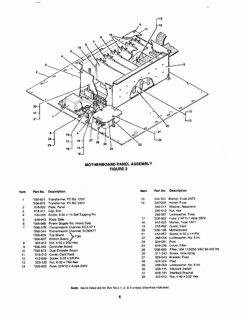
MOTHERBOARD PANEL ASSEMBLY FIGURE 2
Part No. Description
*556-921 Transformer, PC Bd, 120V ‘556-973 Transformer, PC Bd, 240V 616-022 Plate, Panel 616-011 Cap, End 430-205 Screw, 6-32 x l/4 Self Tapping PH
616-012 Plate, Side l 556-989 Power Supply Bd, Heavy Duty *556-378 Transmission Channel, DC5 KFT *556-044 Transmission Channel, DCSOKFT ‘556-829 Top Board ‘556-827 Bottom Board >
FSK
322-012 Nut, 4-40 x 3/32 Hex ‘556-042 Controller Board l 556-673 Dual Encoder Board 616-010 Cover, Card Rack 412-059 Screw, 6-32 x 3/8 PH 322-l 23 Nut, 6-32 x 7164 Hex
‘208-023 Fuse, (2AF2) 2 Amps 250V
15 16
17 18 19 20 21 22 23 24 25 26 27 28 29 30 31 32
Part No. Description
544-551 Marker, Fuse 2AF2 240-003 Holder. Fuse 240-011 Washer, Neoprene 240-010 Nut, Hex 268-007 Lockwasher, Fuse
l 208-022 Fuse, (1 AFl) 1 Amp 250V 544-925 Marker, Fuse 1 AFl 218-002 Guide, Card
l 556-106 Motherboard 412-057 Screw, 6-32 x 1 I4 PH 268-004 Lockwasher, No. 8 Int. 524-081 Post 616-206 Cover, Filter
‘206-005 Filter, 1 OA 115/250 VAC 50-400 Hz 51 i-340 Screw, Grounding 629-643 Bracket, Fuse 524-224 Post 288-003 Lockwasher, No. 6 Int. 458-l 15 Interlock Switch 616-l 91 Interlock Bracket 322-012 Nut, 4-40 x 3/32 Hex
Note: Items listed are for Box No’s 1, 2, & 3 unless otherwise indicated.
4

Item Part No. Description
1 218-002 Guide, Card 2 616-011 Cap, End 3 616-021 Plate, Panel 4 616-012 Plate, Side 5 *556-673 Dual Encoder Board 6 430-205 Screw, 6-32 x l/4 Self Tapping PH 7 616-010 Cover, Card Rack 8 412-059 Screw, 6-32 x 3/8 PH 9 322-l 23 Nut, 6-32 x 7/64 Hex
10 ‘556-l 30 Expander Board
EXPANDER BOARD ASSEMBLY FIGURE 3
Item Part No. Description
11 Slot Marker 519-157 Slot “A” Marker 519-l 58 Slot “B” Marker 519-l 59 Slot “c” Marker 519-180 Slot “D” Marker 519-161 Slot “E” Marker 519-162 Slot “F” Marker 519-163 Slot “G” Marker 519-164 Slot “H” Marker 519-165 Slot “J” Marker 519-166 Slot “K” Marker
5
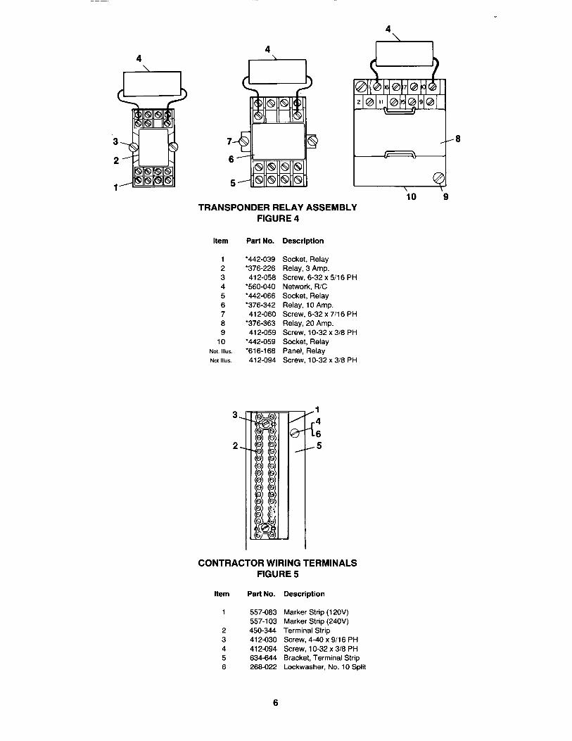
io ‘9 TRANSPONDER RELAY ASSEMBLY
FIGURE 4
Item Part No. Description
1 2 3 4 5 6 7 8 9
10 Not. lllus Not Illus.
3.
2.
*442-039 Socket, Relay l 376-226 Relay, 3 Amp. 412-058 Screw, 6-32 x 5/l 6 PH
‘560-040 Network, R/C ‘442-066 Socket, Relay l 376-342 Relay, 10 Amp. 412-060 Screw, 6-32 x 7/l 6 PH
l 376-363 Relay, 20 Amp. 412-059 Screw, lo-32 x 3/8 PH
‘442-059 Socket, Relay ‘616-l 68 Panel, Relay 412-094 Screw. lo-32 x 3/8 PH
/’ -El
4 8
-5
CONTRACTOR WIRING TERMINALS FIGURE 5
Item Part No. Description
557-083 Marker Strip (12OV) 557-l 03 Marker Strip (240V) 450-344 Terminal Strip 412-030 Screw, 4-40 x 9/l 6 PH 412-094 Screw, 1 O-32 x 3/8 PH 634-644 Bracket, Terminal Strip 268-022 Lockwasher, No. 10 Split
6

i
7 8
5-l
FUSE MODULE ASSEMBLY FIGURE 6
Item Part No. Description
1 2 3 4 5 6 7 8 9
10
544-923 Strip, Marker 450-033 Block, Terminal 412-060 Screw, 6-32 x 7/l 6 PH 240-010 Nut, Hex 288-007 Lockwasher, No. l/2 Int. 544-303 Marker, Fuse 240-003 Holder, Fuse
* 208-023 Fuse, 2 Amps 250 VAC 240-011 Washer, Neoprene 629-908 Bracket
TRANSPONDER WATCH TOUR STATION ASSEMBLY FIGURE 7
Item Part No. Description
1 616-288 Trim Plate 2 520-456 Plate, Name (Per Customer Order) 3 41 l-559 Screw, 6-32 x 318 Oval Hd 4 454-l 18 Bracket, Security Lock (Supplied with 2 Keys) 5 ‘462-081 Toggle Switch
7

Item
4 0 3
2 0
a
13,
12,
1 o- 14
TRANSPONDER REMOTE RELAY STATION ASSEMBLY FIGURE 8
Part No. Description Item Part No. Description
616-298 Trim Plate 8 l 184-011 Diode, IN 4004 412-024 Screw, 4-40 x 3/l 6 PH 9 616-297 Bracket 268-008 Lockwasher, No. 4 Ext. 10 ‘450-378 Terminal Block 322-l 12 Nut, 4-40 x 3/32 Hex. 11 412-030 Screw, 4-40 x 9/l 6 PH
l 376-356 Relay, 2 Amp 12 557-097 Marker Strip l 442-017 Socket, Relay 13 160-011 Clip, Spring 412-026 Screw, 4-40 x 5/l 6 PH 14 41 l-559 Screw, 6-32 x 3/8 Oval Hd.
1
MANUAL RESET ASSEMBLY FIGURE 9
Item Part No. Description
1 616-349 Trim Plate 2 454-l 12 Bracket, Security Lock (Supplied with 2 Keys) 3 l 462-084 Toggle Switch, 10 Amp, 250 VAC 4 41 l-559 Screw, 6-32 x 318 Oval Hd.
8

i
END-OF-LINE RESISTOR ASSEMBLY FIGURE 10
Item Part No. Description Item Part No. Description
616-312 Trim Plate 5 521-297 Label 41 l-559 Screw, 6-32 x 3/8 Oval Hd 6 412-060 Screw, 6-32 x 7/l 6 PH 410-065 Screw, 6-32 x 718 Flat Hd 7 ‘378-161 Resistor, 47K 629-099 Strip, Mounting 8 450-033 Terminal Block
NUMERICAL LISTING OF FIELD SERVICE PARTS
Part No. Description
112-044 Battery, 12V (See Figure 1) 112-045 Battery, 12V (See Figure 1) 184-011 Diode, IN 4004 (See Figure 8) 206-005 Filter, 1 OA, 115/250VAC, 50-400 Hz (See Figure 2) 208-001 Fuse, .5 Amp. (See Figure 1) 208-022 Fuse, (1AFl) 1 Amp., 250V (See Figure 2) 208-023 Fuse, 2 Amps., 250V (See Figures 2 & 6) 240-023 Holder, Fuse (See Figure 1) 266-012 Nut, Case Lock Mounting (See Figure 1) 266-049 Lock Washer, 3/4” ID Int. (See Figure 1) 266-053 Lock, Type “B” (See Figure 1) 376-226 Relay, 3 Amp. (See Figure 4) 376-342 Relay, 10 Amp. (See Figure 4) 376-356 Relay, 2 Amp. (See Figure 8) 376-363 Relay, 20 Amp. (See Figure 4) 378-l 61 Resistor, 47K (See Figure 10) 442-017 Socket, Relay (See Figure 8) 442-039 Socket, Relay (See Figure 4) 442-059 Socket, Relay (See Figure 4) 442-066 Socket, Relay (See Figure 4) 450-378 Terminal Block (See Figure 8) 462-081 Toggle Switch (See Figure 7) 462-084 Toggle Switch, 10 Amp, 250VAC (See Figure 9) 556-040 Network, R/C (See Figure 4) 558-042 Controller Board (See Figure 2) 558-044 Transmission Channel, DC50 KFT (See Figure 2) 556-l 06 Motherboard (See Figure 2) 556-l 23 PC Bd Zone Interface Assy. (See Figure 1) 556-l 30 Expander Board (See Figure 3)
(continued)
9

556378 556-471 556-673 556-827 556-829 556-921 556-973 556-989 616-l 68 696-819 696-820 733-066 733-070 733-l 45 733-l 46
NUMERICAL LISTING OF FIELD SERVICE PARTS (cont’d)
Transmission Channel, DC5 KFT (See Figure 2) Lightning Suppressor Board (See Figure 1) Dual Encoder Board (See Figures 2 & 3) Bottom Board (FSK) (See Figure 2) Top Board (FSK) (See Figure 2) Transformer PC Bd, 12OV (See Figure 2) Transformer PC Bd, 240V (See Figure 2) Power Supply Bd, Heavy Duty (See Figure 2) Panel, Relay (See Figure 4) Bushing (See Figure 1) Pin Hinge (See Figure 1) Harness, 3” Length (from Motherboard to Expander Bd) (See Figure 1) Harness, 34” Length (See Figure 1) Harness, Power Transmission (4 & 6 Unit) (See Figure 1) Harness, Power Transmission (2 Unit) (See Figure 1)
10


‘9 . .
Simplex Time Recorder Co., l Simplex Plaza l Gardner, Massachusetts 01441 U.S.A. MUX1 -81-002 1
saSimplex
‘\