(698 KB) - PIER
22
Progress In Electromagnetics Research B, Vol. 51, 367–388, 2013 FOCUSING, POWER TUNNELING AND REJECTION FROM CHIRAL AND/OR CHIRAL NIHILITY/NIHILITY METAMATERIALS LAYERS Syed T. H. Shah 1 , Faiz Ahmad 2 , Nayyar A. Shah 1 , Aqeel A. Syed 1 , and Qaisar A. Naqvi 1, * 1 Department of Electronics, Quaid-i-Azam University, Islamabad 45320, Pakistan 2 Department of Electronics, CIIT, Islamabad, Pakistan Abstract—Focusing of electromagnetic plane wave from a large paraboloidal reflector, composed of layers of chiral and/or chiral nihility metamaterials, has been studied using Maslov’s method. As a first step, the transmission and reflection of electromagnetic plane wave from two parallel layers of chiral and/or chiral nihility metamaterials are investigated using transfer matrix method. The effects of change of angle of incidence, chirality parameters and impedances of layers are noted and discussed. Special cases by taking extreme values of permittivity of second layer, while assuming value of corresponding chirality equal to zero, are also obtained for validating the methodology. These special cases are equivalent to reflection from a perfect electric conductor backed chiral layer and nihility backed chiral layer, respectively. Results of reflection from parallel layers have been utilized to study focusing from a large paraboloidal reflector. The present study, on focusing from a paraboloidal reflector, not only unifies already published work by various researchers but also provides better understanding of the problem. 1. INTRODUCTION Chiral media have been well known in the optical frequency range because of its special properties. Of these properties, optical activity and circular dichroism are of particular interest [1–6]. Chiral medium can be thought as composed of numerous randomly oriented chiral objects which can never be brought into congruence with their mirror Received 7 March 2013, Accepted 3 May 2013, Scheduled 8 May 2013 * Corresponding author: Qaisar Abbas Naqvi ([email protected]).
Transcript of (698 KB) - PIER

Progress In Electromagnetics Research B, Vol. 51, 367–388, 2013
FOCUSING, POWER TUNNELING AND REJECTIONFROM CHIRAL AND/OR CHIRAL NIHILITY/NIHILITYMETAMATERIALS LAYERS
Syed T. H. Shah1, Faiz Ahmad2, Nayyar A. Shah1,Aqeel A. Syed1, and Qaisar A. Naqvi1, *
1Department of Electronics, Quaid-i-Azam University, Islamabad45320, Pakistan2Department of Electronics, CIIT, Islamabad, Pakistan
Abstract—Focusing of electromagnetic plane wave from a largeparaboloidal reflector, composed of layers of chiral and/or chiralnihility metamaterials, has been studied using Maslov’s method.As a first step, the transmission and reflection of electromagneticplane wave from two parallel layers of chiral and/or chiral nihilitymetamaterials are investigated using transfer matrix method. Theeffects of change of angle of incidence, chirality parameters andimpedances of layers are noted and discussed. Special cases by takingextreme values of permittivity of second layer, while assuming value ofcorresponding chirality equal to zero, are also obtained for validatingthe methodology. These special cases are equivalent to reflection froma perfect electric conductor backed chiral layer and nihility backedchiral layer, respectively. Results of reflection from parallel layers havebeen utilized to study focusing from a large paraboloidal reflector.The present study, on focusing from a paraboloidal reflector, not onlyunifies already published work by various researchers but also providesbetter understanding of the problem.
1. INTRODUCTION
Chiral media have been well known in the optical frequency rangebecause of its special properties. Of these properties, optical activityand circular dichroism are of particular interest [1–6]. Chiral mediumcan be thought as composed of numerous randomly oriented chiralobjects which can never be brought into congruence with their mirror
Received 7 March 2013, Accepted 3 May 2013, Scheduled 8 May 2013* Corresponding author: Qaisar Abbas Naqvi ([email protected]).
368 Shah et al.
images by any translation or rotation [7–10]. Many objects found innature can be regarded as chiral: such as irregular tetrahedrons, sugarmolecules and wire helices. In fact the word “chirality” is derived fromthe Greek word “cheir” having meaning of hand; an object possessingabove mentioned property of incongruence with its mirror image. Inscience particular word “chirality” instead of dissymmetry was firstintroduced by Lord Kelvin, Professor of natural philosophy in theUniversity of Glasgow. Now this word is used to describe the mediamicroscopically composed of the chiral objects.
When linearly polarized wave falls on a slab of chiral medium, itsplits into two circularly polarized waves: one left circularly polarizedand the other right circularly polarized [8–10]. After passing throughthe slab the two waves combine to yield a linearly polarized wavewhose plane of polarization is rotated with respect to that of theplane of polarization of the incident wave. Effect of chirality of themedium which rotates the plane of linearly polarized wave passingthrough it is studied by Arago [1], Biot [2] and Fresnel [3]. Thisphenomenon is named as optical activity of the medium. The amountof rotation depends upon the distance traveled by the wave in the slab.This phenomenon is named as circular birefringence. The phenomenacircular dichroism alludes to the fact that different amount of fieldabsorbtion for the left and right circularly polarized waves occurs asthey pass through the chiral media. The constitutive relations forchiral metamaterial [8] are given below,
D = εE + iκH (1)B = µH − iκE (2)
The behavior of propagation and radiation of the field in chiral mediumhas been investigated by several authors [8–10].
Left-handed or double negative (DNG) materials are metamateri-als in which electric, magnetic and the wave vectors follow the so calledleft hand rule. In fact the behavior of electromagnetic waves in “lefthanded media” goes back a long way, e.g., Lamb [11], Schuster [12],Pocklington [13] and Malyuzhinets [14] contributed on this topic. Theactual study of waves in media with simultaneously negative permittiv-ity and permeability was first done by Sivukhin [15]. Veselago in detailstudied the interesting property of negative refraction in left handedmaterials [16]. In chiral medium, negative real parts of the permittiv-ity and permeability lead an isotropic chiral medium to exhibit circulardichroism that is reverse with respect to that exhibited by an identicalmedium but with positive real parts of permittivity and permeabil-ity. Left handed materials exhibit some other interesting properties,namely, backward wave and double negative parameters [17]. Negative

Progress In Electromagnetics Research B, Vol. 51, 2013 369
refraction can also be achieved by using the chiral metamaterials [18–21]. In chiral matematerials strong enough chirality produces negativerefractive index for one of the eigenwaves [22, 23].
In electromagnetics, Lakhtakia introduced the concept of nihilitymetamaterial for a material whose permittivity and permeabilityapproach to zero [24]. Constitutive relations for nihility metamaterialare,
D = 0 (3)B = 0 (4)
Lakhtakia showed that propagation is not possible in nihilitymetamaterial. Later, Tretyakov et al. [25] extended this concept ofnihility for the isotropic chiral medium. A chiral nihility metamaterialis one for which, at certain value of frequency, real parts of permittivityand permeability both are simultaneously zero. That is, ε → 0, µ → 0and κ 6= 0 at nihility frequency. Constitutive relations for chiral nihilitymetamaterials are,
D = iκH (5)B = −iκE (6)
Chiral nihility metamaterial has two wavenumbers of equal magnitudebut opposite signs. When a dielectric-chiral nihility half space isexcited by an oblique incident linearly polarized plane wave, twocircularly polarized plane waves having opposite handedness areproduced. One of them is forward wave while the other is backwardwave which gives rise to the phenomenon of negative refraction in chiralnihility metamaterial.
If a perfect electric conductor (PEC) interface placed in chiralnihility metamaterial is excited by a forward plane wave. Only onereflected wave parallel to the incident wave is produced, i.e., negativereflection happens. The reflected wave is backward wave whichcancels the incident forward wave to produce zero power propagation.Interestingly, if a chiral nihility slab backed by PEC interface is excitedby linearly polarized plane wave, effect of each eigenwave in chiralnihility after reflection from PEC interface is canceled leading to asituation as if front face of the geometry is PEC and there is no chiralslab [26]. A PEC waveguide coated with chiral nihility metamaterialconfines propagation of power within un-coated region of the guide [27].
In electromagnetics, Brewster angle is defined as angle ofincidence for which reflection power is zero. In all introductorytext books on electromagnetic theory [28, 29], reflection of verticallypolarized (parallel polarized or transverse magnetic (TM)) planewave and horizontally polarized (perpendicular polarized or transverse

370 Shah et al.
electric (TE)) plane wave from a dielectric-dielectric half spaceboundary is usually presented to explain the concept of Brewsterangle. It is mentioned that vertically polarized wave experiences zeroreflection at one incident angle whereas, reflection is non-zero forhorizontal polarization for all angles. This means that if dielectric-dielectric half space is excited by a wave, having both the vertical andhorizontal polarizations, at the Brewster angle the reflected wave willbe linearly polarized with horizontal polarization only. The angle ofincidence that allows total reflection of power from a planar dielectric-dielectric interface is known as critical angle. Critical angle exists onlyfor perpendicular polarization if the wave propagates from a denserdielectric medium to a rare dielectric.
In the same context, reflection of plane wave from an interfaceof an achiral dielectric and a chiral/chiral nihility metamaterial wasdiscussed by Qiu et al. [30]. Their study reveals that for certain valuesof constitutive parameters, the results opposite to that of conventionaldielectric-dielectric interface can also be achieved. That is, existence ofzero reflection for only parallel polarization in the dielectric-chiral caseis possible. They also showed that, for certain values it is possible tohave no Brewster angle for both polarizations and total reflection canbe achieved for a wide range of incident angles. Power correspondingto the electromagnetic waves associated with a planar interface of twochiral and/or chiral nihility metamaterials excited by a plane wavewas studied by Ahmad et al. [31]. Their results suggest interestingcharacteristics such as complete power transmission/rejeection andband pass/band reject filter of the interface.
2. GO FIELD AND MASLOV’S METHOD
Geometrical optics (GO) is a powerful tool for the study of wave motionat high frequencies [32–34]; however, it fails at the caustics. A causticis a region where area of a ray tube is zero and hence introduces amathematical singularity when ever intensity per unit area is needed tobe counted, though physically this is not the case. Physically the fieldis always finite at caustics and caustics are of practical interest in manyapplications including defense and medical sciences. Maslov proposedan alternative method to find the fields in the caustic region [35].Maslov’s method combines the simplicity of asymptotic ray theory andthe generality of the Fourier transform method. This is achieved byrepresenting the GO fields in terms of mixed coordinates consistingof wave vector coordinates and spatial coordinates. Maslov’s methodhave been applied to study the field near the caustics of the focusingsystems by many authors [36–45]. Focusing from a PEC cylindrical and

Progress In Electromagnetics Research B, Vol. 51, 2013 371
spherical reflectors using Maslov’s method was first treated by Ji andHongo [38]. Faryad and Naqvi extended this work for reflector coatedwith chiral metamaterial [44]. Illahi and Naqvi studied the focusingfrom chiral nihility coated PEC and perfect electromagnetic conductor(PEMC) cylindrical reflector [46]. In the present work, one interest isalso to unify all these cases so that these become special cases of thegeometry, under investigation.
Consider a three dimensional vector wave equation, in cartesiancoordinates r = (x, y, z), describing the field in medium havingwavenumber k0
∇2U(r) + k20U(r) = 0
Expressing the solution U(r) of wave equation in terms of wellknown Luneberg-Kline series yields Eikonal equation for phase s(r)and transport equation for amplitude. For homogeneous and losslessmedium, Eikonal equation reduces to Hamiltonian equation as
H(r,p) = (p · p− 1)/2 = 0, p = ∇s (7)where p is the wave vector. The solution of Hamiltonian equation isgiven belowx=ξ+pxt, y=η+pyt, z=ζ+pzt, px =px0 , py =py0 , pz =pz0
where (ξ, η, ζ) and (px0 , py0 , pz0) are the initial values of cartesiancoordinates (x, y, z) and wave vector coordinates (px, py, pz)respectively and t is parameter along the ray. Finite field aroundcaustic may be obtained using following expression obtained fromMaslov’s method [34, 40]
U(r) =k0
2π
∫ ∞
−∞
∫ ∞
−∞E(r0)
[D(t)D(0)
∂(px, py)∂(x, y)
]−1/2
exp(−ik0(s0 + t− x(px, py, z)px − y(px, py, z)py
+xpx + ypy))dpxdpy
where U(r) denotes the electric field strength. D(t)D(0) is the Jacobian
for transformation from ray coordinates to cartesian coordinate and s0
represents the initial phase. Above equation provides uniform solutionaround the caustic.
In this paper, transmitted and reflected powers from two parallellayers of chiral and/or chiral nihility metamaterials with changing angleof incidence and chiralities of the layers are analyzed. Limiting casesof permittivity, with value of chirality fixed to zero, are also takeninto account and their interpretation given. Focusing from a large sizeparaboloidal reflector, composed of two layers of chiral and/or chiralnihility metamaterials, is studied by utilizing the Maslov’s method togive the remedy of GO which fails at caustic.

372 Shah et al.
3. FORMULATION
Consider a geometry consisting of two infinite parallel layers of chiralmetamaterials placed in air as shown in Figure 1. Physical width of thetwo layers is taken as d1 and d2, respectively. Constitutive parametersfor the two layers are denoted by (ε1, µ1, κ1) and (ε2, µ2, κ2),respectively. Air in which layers are placed have constitutiveparameters ε0 and µ0.
Figure 1. Fields representation inside and outside the layers.
The above mentioned geometry is excited by an oblique incidentlinearly polarized electromagnetic plane wave. θi, θr and θt are theangles of incidence, reflection and transmission with respect to thewalls of layers, respectively. As chiral medium supports two circularlypolarized eigen waves having different wavenumbers so fields in eachlayer are written as linear combination of left circularly polarized(LCP) and right circularly polarized (RCP) plane waves. Both LCPand RCP waves propagate in forward as well as backward direction ineach layer. The wavenumbers of both eigen waves in a chiral media aredifferent. Refractive indices, wavenumbers and intrinsic impedance ofthe medium for first chiral layer are
n1(R,L) =√
εr1µr1 ± κ1 (8)k1(R,L) = ω (
√ε1µ1 ± κ1) (9)

Progress In Electromagnetics Research B, Vol. 51, 2013 373
η1 =√
µ1
ε1, (10)
where n1R and k1R are refractive index and wavenumber for RCP wave,respectively. Quantity εr1 = ε1/ε0 is the relative permittivity of themedium occupying first layer.
For second chiral layer, these quantities are
n2(R,L) =√
εr2µr2 ± κ2 (11)k2(R,L) = ω (
√ε2µ2 ± κ2) (12)
η2 =√
µ2
ε2. (13)
Wavenumber and intrinsic impedance of the host medium are given as,
η0 =√
µ0/ε0 (14)k0 = ω
√µ0ε0. (15)
Expressions for the incident and reflected fields and the fieldtransmitted after passing through both the layers are given in thefollowing:
Einc= [Ei‖(az sin θi + ax cos θi) + Ei⊥ay] exp[−ik0(z cos θi − x sin θi)] (16)Hinc=1/η0[−Ei⊥(az sin θi+ax cos θi)+Ei‖ay] exp[−ik0(z cos θi−x sin θi)] (17)Eref = [Er‖(−az sin θr + ax cos θr) + Er⊥ay] exp[ik0(z cos θr + x sin θr)] (18)Href =1/η0[Er⊥(−az sin θr+ax cos θr)−Er‖ay] exp[ik0(z cos θr+x sin θr)] (19)Etra= [Et‖(az sin θt + ax cos θt) + Et⊥ay] exp[−ik0(z cos θt − x sin θt)] (20)Htra=−1/η0[Et⊥(az sin θt+ax cos θt)−Et‖ay] exp[−ik0(z cos θt−x sin θt)] (21)
In the above equations, Er‖, Er⊥, Et‖, and Et⊥ are unknowncoefficients corresponding to parallel and perpendicular componentsof the respective fields.
Expressions of fields inside each chiral layer can be written as,
Ep+ = EfL[(ax cos θpL + az sin θpL) + iay]exp[−ikpL(z cos θpL − x sin θpL)]+EfR[(ax cos θpR + az sin θpR)− iay]exp[−ikpR(z cos θpR − x sin θpR)] (22)
Hp+ =−(i/ηp)EfL[(ax cos θpL + az sin θpL) + iay]× exp[−ikpL(z cos θpL − x sin θpL)]+(i/ηp)EfR[(ax cos θpR + az sin θpR)− iay]× exp[−ikpR(z cos θpR]− x sin[θpR)] (23)
Ep− = EbL[(−az sin θpL + ax cos θpL) + iay]
374 Shah et al.
exp[ikpL(z cos θpL+x sin θpL)]EbR[(−az sin θpR + ax cos θpR)− iay]exp[ikpR(z cos θpR + x sin θpR)] (24)
Hp− =−(i/ηp)EbL[(−az sin θpL + ax cos θpL) + iay]× exp[ikpL(z cos θpL + x sin θpL)]+(i/ηp)EbR[(−az sin θpR + ax cos θpR)− iay]× exp[ikpR(z cos θpR + x sin θpR)] (25)
where kpL and kpR represent the wavenumbers for LCP and RCPwaves, respectively. Value of p, either 1 or 2, describes fields for firstor the second layer, whereas, subscripts b and f are used to representforward and backward waves, respectively. In the above equations, EfL,EfR, EbL, and EbR are unknown coefficients. Tangential components offields are continuous at interfaces located at z = 0, d1, d1+d2 and theseboundary conditions are used to find the unknown coefficients. Snell’slaw is used to determine the relation among the angles of incidence,reflection and transmission by using following relations:
θr = θi
k0 sin θi = k1(R,L) sin θ1(R,L) = k2(R,L) sin θ2(R,L) = kt sin θt,
where k0 and kt denote the wavenumbers for medium before andafter the layers and are equal when these two layers are placed inair. Using transfer matrix method (TMM) discussed in [47], threematching matrices each relating the fields at an interface are obtained.Moreover, two 4 × 4 propagation matrices, linking fields between twoconsecutive interfaces are also obtained. Numerical results for powerscorresponding to parallel and perpendicular components of transmittedand reflected fields are obtained in the following. In Section 2, it isassumed that optical width of each layer is λ0/4, where λ0 is wavelength in air corresponding to the operating frequency.
4. RESULTS AND DISCUSSION
In this section, numerical results for powers corresponding to paralleland perpendicular components of the reflected and transmitted fieldsare presented and analyzed. Four different cases, summarized below,are considered for this purpose.
i. Both layers are of chiral metamaterials (c-c).ii. First layer is of chiral nihility and second is of chiral metamaterial
(cn-c).iii. First layer is of chiral whereas second is of chiral nihility
metamaterial (c-cn).

Progress In Electromagnetics Research B, Vol. 51, 2013 375
iv. Both layers are of chiral nihility metamaterials (cn-cn).
Results corresponding to above cases are shown by Figure 3 to Figure 9.In addition to the above, the limiting cases of permittivity of
second layer while keeping κ2 = 0 are also considered for the discussion.In these situations, the above four cases essentially present followingscenario.
a. First layer is of chiral metamaterial whereas permittivity of secondlayer is taken very large with chirality κ2 equal to zero making itessentially a PEC boundary (c-PEC).
b. First layer is of chiral nihility metamaterial whereas permittivityof second layer is taken very large with chirality κ2 equal to zero(cn-PEC).
c. First layer is of chiral. metamaterial whereas permittivity ofsecond layer is taken very small with chirality κ2 equal to zeromaking it essentially a nihility interface (c-n).
d. First layer is of chiral nihility metamaterial whereas permittivityof second layer is taken very small with chirality κ2 equal to zero(cn-n).
Results corresponding to above situations are depicted throughFigure 10 to Figure 13. ‖ and ⊥ signs are used to represent power forparallel and perpendicular components, respectively. For example: c-c‖and c-c⊥ represent parallel and perpendicular components of power forchiral-chiral cases, respectively.
In Figure 2, power corresponding to parallel and perpendicularcomponents of reflected fields versus angle of incidence is shown.
cn-c
c-cn
c-c
cn-cn c-c
c-cn
cn-cn
cn-c
0 20 40 60 80 inc
|| and reflected power vs angle of incidence| |
||
θ
0.0
0.2
0.4
0.6
0.8
1.0
pow
er
||
||
||
| |
| |
| |
| |
Figure 2. ehavior of thereflected power for parallel andperpendicular field components.κ1 = 0.25, κ2 = 0.75, η1 = η2 = 2.
c-c
cn-cn
cn-cncn-c
c-cn
c-c cn-c
c-cn
0 20 40 60 800.0
0.2
0.4
0.6
0.8
1.0
inc
pow
er
|| and transmitted power vs angle of incidence
||
θ
| |
||
||
||
| |
| |
| |
| |
Figure 3. Behavior of transmit-ted power for parallel and perpen-dicular field components. κ1 =0.25 κ2 = 0.75, η1 = η2 = 2.

376 Shah et al.
It is assumed that the intrinsic impedances of metamaterials fillingboth layers are same. Figure contains plots for four different cases,i.e., c-c, cn-c, c-cn, and cn-cn. Brewster angle is defined as theangle of incidence for which reflection of power, both for paralleland perpendicular components, is zero. Reflected powers for c-c caseare zero for θi < 23◦ and this gives a range of brewster angles. Inthe case of cn-cn, a range of Brewster angles exists for θi < 17.5◦.After this range, power for parallel component increases whereaspower for perpendicular component remains negligible for the entirerange of incident angles. In the case of cn-c, parallel component isnonzero everywhere and near grazing incidence almost total reflectionof power happens whereas power for perpendicular component remainsnegligible through the entire range of incident angles. It may be notedthat range of Brewster angles exist only for c-c and cn-cn cases andrange of angles yielding almost total reflection exists only for parallelcomponent of cn-c case. For c-cn case, power only for perpendicularcomponent is zero for θi < 27.5◦ and corresponding parallel componentis nonzero everywhere.
Figure 3 describes behavior of the parallel and perpendicularcomponents of transmitted powers for impedance matching of bothlayers. For c-c case, power for parallel and perpendicular componentshave same initial amplitude, i.e., 0.5. Considering cn-c case, powerof both parallel and perpendicular components of transmitted powerfollow each other and decrease gradually with incidence angle. In c-cncase, perpendicular component is dominant over parallel componentwhereas for cn-cn case, it is observed that power of parallel componentis dominant over the perpendicular component.
Figure 4 shows the behavior of reflected power for layers havingdifferent intrinsic impedances. For c-c and cn-c cases, no Brewsterangle exists and power for parallel component is dominant overcorresponding perpendicular component. For c-c case, reflected poweronly for perpendicular component is zero for θi < 34.3◦ and θi > 85◦.For cn-c case, when θi > 22◦, power for parallel component of reflectedfield starts increasing and after θi = 80◦, almost total reflection isobserved because perpendicular component has insignificant reflectedpower. Perpendicular component has very low value between θi =34.3◦ and θi = 78◦ and is zero elsewhere. Both c-cn and cn-cn caseshave same range of Brewster angles, i.e., θi ≤ 11.46◦.
Figure 5 is about transmitted power in case of impedancemismatch. For c-c case, both components of power have equalcontribution at θi = 31.5◦. For cn-c and cn-cn cases, power for parallelcomponent has higher values and follows the power for correspondingperpendicular component.

Progress In Electromagnetics Research B, Vol. 51, 2013 377
cn-c
c-c cn-cnc-cn
c-cn
c-c cn-cn
cn-c
0 20 40 60 800.0
0.2
0.4
0.6
0.8
1.0
inc
pow
er
θ
|| and reflected power vs angle of incidence| |
||
|| ||
||
| |
| |
| |
| |
Figure 4. Behavior of reflectedpower for parallel and perpendic-ular field components. κ1= κ2 =0.25, η1 = 1 and η2 = 2.
cn-cn
c-cn
cn-c
c-cn
cn-cn
cn-c
c-c c-c
0 20 40 60 80incθ
|| and transmitted power vs angle of incidence
||
0.0
0.2
0.4
0.6
0.8
1.0
pow
er
||
||
|| | |
| |
| |
| |
| |
Figure 5. Behavior of trans-mitted power for parallel andperpendicular field components.κ1=κ2 = 0.25, η1 = 1 and η2 = 2.
cn-cn
cn-c c-cn c-cn
cn-cn
c-cc-c
cn-c
0 1 2 3 4 5 1
reflected power vs chirality κ1|| and
κ
| |
||
0.0
0.2
0.4
0.6
0.8
1.0
pow
er
||
||
||
| |
| |
| |
| |
Figure 6. Behavior of reflectedpower for parallel and perpendic-ular field components. κ2 = 0.25,θi = π/4 and η1 = η2 = 2.
c-c c-c
cn-c
c-cn
cn-cn
c-cn
cn-cn
cn-c
0 1 2 3 4 50.0
0.2
0.4
0.6
0.8
1.0
1
pow
er
1transmitted power vs chirality κ
κ
|| and | |
||
||
||
||
| |
| |
| |
| |
Figure 7. Behavior of transmit-ted power for parallel and perpen-dicular field components. κ2 =0.25, θi = π/4, η1 = η2 = 2.
Figure 6 shows plots of power for impedance matching case versuschirality of the first layer. For the purpose of analysis chiralityvalues are considered between 0 and 5. For cn-c case, almost totalpower reflection in terms of parallel component occurs at very lowvalues of chirality and perpendicular component is almost zero forconsidered range of chirality. For c-cn case, zero reflection of parallelpower component is obatined at chirality value κ1 = 1.9 whereas atκ1 = 1.8, 2.2, 4 perpendicular component of reflected power is zero. Incn-cn case, oscillating behavior is observed for both components withperiodic behavior for cn-cn⊥. At κ1 = 0, 2, 4 perpendicular componentof power becomes zero and at κ1 = 1, 3, 5 parallel component of power
378 Shah et al.
is zero. At κ1 = 0, total reflection occurs. Zeros of parallel andperpendicular components of power at specific values of chirality canbe used to get or avoid particular component of polarization.
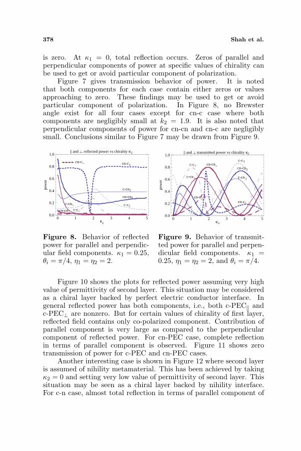
Figure 7 gives transmission behavior of power. It is notedthat both components for each case contain either zeros or valuesapproaching to zero. These findings may be used to get or avoidparticular component of polarization. In Figure 8, no Brewsterangle exist for all four cases except for cn-c case where bothcomponents are negligibly small at k2 = 1.9. It is also noted thatperpendicular components of power for cn-cn and cn-c are negligiblysmall. Conclusions similar to Figure 7 may be drawn from Figure 9.
cn-c
c-cn
cn-cn
c-c c-ccn-cn
c-cn
cn-c
0 1 2 3 4 5 2
2reflected power vs chirality κ
κ
|| and | |
||
0.0
0.2
0.4
0.6
0.8
1.0
pow
er
||
||
||
| |
| |
| | | |
Figure 8. Behavior of reflectedpower for parallel and perpendic-ular field components. κ1 = 0.25,θi = π/4, η1 = η2 = 2.
c-c cn-cn
cn-c
c-cn
c-c
cn-cn
c-cn
cn-c
0 1 2 3 4 52
2
transmitted power vs chirality κ
κ
|| and | |
||
||
||
||
0.0
0.2
0.4
0.6
0.8
1.0po
wer
| | | |
| |
| |
Figure 9. Behavior of transmit-ted power for parallel and perpen-dicular field components. κ1 =0.25, η1 = η2 = 2, and θi = π/4.
Figure 10 shows the plots for reflected power assuming very highvalue of permittivity of second layer. This situation may be consideredas a chiral layer backed by perfect electric conductor interface. Ingeneral reflected power has both components, i.e., both c-PEC‖ andc-PEC⊥ are nonzero. But for certain values of chirality of first layer,reflected field contains only co-polarized component. Contribution ofparallel component is very large as compared to the perpendicularcomponent of reflected power. For cn-PEC case, complete reflectionin terms of parallel component is observed. Figure 11 shows zerotransmission of power for c-PEC and cn-PEC cases.
Another interesting case is shown in Figure 12 where second layeris assumed of nihility metamaterial. This has been achieved by takingκ2 = 0 and setting very low value of permittivity of second layer. Thissituation may be seen as a chiral layer backed by nihility interface.For c-n case, almost total reflection in terms of parallel component of

Progress In Electromagnetics Research B, Vol. 51, 2013 379
c-PEC
c-PEC
cn-PEC
cn-PEC
0 1 2 3 4 50.0
0.2
0.4
0.6
0.8
1.0
1
pow
er
1reflected power vs chirality κ
κ
|| and
||
||
| | | |
| |
Figure 10. Behavior of reflectedpower for parallel and perpendic-ular field components. θi = π/4,η1 = 2, ε2 = 105, κ2 = 0.
0 1 2 3 4 5 1
1transmitted power vs chirality κ
κ
0.0
0.2
0.4
0.6
0.8
1.0
pow
er
|| and | |
Figure 11. Behavior of trans-mitted power for parallel and per-pendicular field components. θi =π/4, η1 = 2, ε2 = 105, κ2 = 0.
cn-n
cn-n
c-n
c-n
0 1 2 3 4 5 1
1reflected power vs chirality κ
κ
||
|| and | |
||
0.0
0.2
0.4
0.6
0.8
1.0
pow
er
| |
| |
Figure 12. Behavior of reflectedpower for parallel and perpendic-ular field components. θi = π/4,η1 = 2, ε2 = 10−5, κ2 = 0.
0 1 2 3 4 51
pow
er
1
κ
transmitted power vs chirality κ || and | |
0.0
0.2
0.4
0.6
0.8
1.0
Figure 13. Behavior of trans-mitted power for parallel and per-pendicular field components. θi =π/4, η1 = 2, ε2 = 10−5, κ2 = 0.
the reflected power is observed. For the case of cn-n, perpendicularcomponent of reflected power has also significant contribution forcertain range of chirality. It is noted that for certain range of chirality,overlap of cn-n and c-n cases happen. Figure 13 shows plots oftransmitted power for c-n and cn-n cases and no transmission of poweris obtained. It may be noted that conclusions drawn from Figure 10to Figure 13 agree with published work.
Focusing of electromagnetic waves from a paraboloidal reflectorcomposed of chiral and/or chiral nihility metamaterial using theMaslov’s method is studied in next section. PEC and nihility backedchiral/chiral nihility paraboloidal reflector are also discussed.

380 Shah et al.
5. EVALUATION OF FINITE FIELD AROUND FOCUS
Consider a bilayer paraboloidal reflector placed in air as shown inFigure 14. The equation for the surface of a paraboloidal reflectoris given by,
ζ = g(ξ, η) = f − ρ2
4f= f − ξ2 + η2
4f(26)
where (ξ, η, ζ) are the Cartesian coordinate of any point on the surfaceof paraboloidal reflector. f is the focal length of the paraboloidalreflector and ρ2 = ξ2 + η2.
The incident field traveling along z axis is expressed as,
Ei = ax exp (−ik0z) (27)
The incident plane wave makes an angle α with surface normal, wheresurface normal is given as,
an = sin α cos γax + sinα sin γay + cos αaz (28)
where α and γ are given as,
sinα =ρ√
ρ2 + 4f2, (29)
cosα =2f√
ρ2 + 4f2, (30)
tan γ =η
ξ(31)
The wave reflected from paraboloidal reflector is given below,
Er = E0 exp[ik0(x sin 2α cos γ + y sin 2α sin γ + z cos 2α)] (32)
Figure 14. Reflection from a paraboloidal reflector placed in air.

Progress In Electromagnetics Research B, Vol. 51, 2013 381
Rectangular components of field E0, at the surface of reflector, aregiven below,
Ex0 = B⊥ sin2 γ −B‖ cos2 γ cos 2α (33)Ey0 = − cos γ sin γ(B‖ cos 2α + B⊥) (34)Ez0 = B‖ sin 2α cos γ (35)
where B‖ and B⊥ are parallel and perpendicular components of GOreflected field from planar layers of chiral and/or chiral nihility layers.The field expression in polar coordinates which is valid around thefocal point is given below [40],
Er =i2k0f
π
∫ H
0
∫ 2π
0×Er0 tanα exp[−ik0(2f−r sin θ sin 2α cos(φ−γ)
−r cos θ cos 2α)]dαdγ (36)The upper limit of integration with respect to α is taken as,
H = tan−1 (D
2f)
where D is the height of the paraboloidal reflector from horizontal axis.
6. NUMERICAL RESULTS AND DISCUSSION
The field behavior around the focal region of a paraboloidal reflectorare obtained by solving the equation, obtained using Maslov’smethod. Numerical results are presented with the variation of differentparameters, i.e., chirality, relative permittivity and thickness of thelayer. Chiral nihility is introduced as limiting case of chiral mediumwhere value of relative permittivity and relative permeability of thechiral medium is assumed as 10−5, keeping nonzero chirality whereasfor nihility material, the value of chirality parameter is taken equalto zero. In all the simulations, parameters (k0, f, H) are taken as(1, 100, π/4). For all cases, permeability of each chiral layer is takenas unity. All plots deal with behavior of |U(r)| versus kz.
6.1. Chiral-chiral Paraboloidal Reflector
From Figure 15 and Figure 16, it is noted that increasing thepermittivity of each layer of the paraboloidal reflector increases thestrength of electric field around the focus. Comparison of Figures 15and 16 also shows that strength of field around focus is more dependenton the permittivity of second layer.
In Figure 17 and Figure 18, effects of variation of thickness of eachlayer of paraboloidal reflector are presented. It is noted that increase

382 Shah et al.
r1 =4 r1 =1
r1 =9
1 2
r2 =1
-20 -10 0 10 20kz
10
20
30
40
κ =κ =0.25
|U(r)|
Figure 15. Field behavioraround focus for different valuesof permittivity of first layer: d1 =d2 = λ0
4 , c-c case.
r2 =4 r2 =1
r2 =91 2
r1 =1
-20 -10 0 10 20kz
10
20
30
40
κ =κ =0.25
|U(r)|
Figure 16. Field behavioraround focus for different valuesof permittivity of second layer:d1 = d2 = λ0
4 , c-c case.
d1 0 /6d1 0 /5d1= 0 /4
r1 =1r2 =4
1 2
-20 -10 0 10 20kz
10
20
30
40
κ =κ =0.25λ
λ
λ
|U(r)|
==
Figure 17. Field behavioraround focus for different valuesof thickness of first layer: d2 = λ0
4 ,c-c case.
d2
d2 d2
-20 -10 0 10 20kz
10
20
30
40
= 0 /6= 0 /5
= 0 /4
r1 =1r2 =4
1 2κ =κ =0.25 λ
λ
λ
|U(r)|
Figure 18. Field behavioraround focus for different valuesof thickness of second layer: d1 =λ04 , c-c case.
of thickness of first or second layer also increases the strengths of fieldaround focus. It is noticed that first layer has more impact on the fieldstrength as compared to the variation of thickness of the second layer.
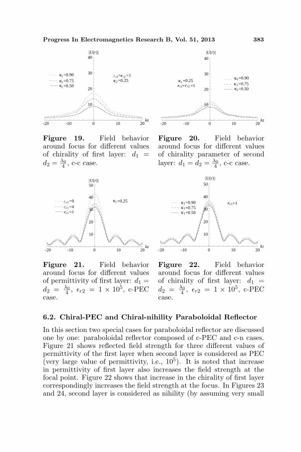
Figures 19 and 20 show the effect of change of chirality parameterof each layer while keeping all the other parameters fix. It is observedthat increase in chirality of each layer also strengthen the field aroundfocal point of the paraboloidal reflector. Change in chirality of firstlayer produces greater change in reflected field strength around thefocal point as compared to chirality variation for second layer.
Progress In Electromagnetics Research B, Vol. 51, 2013 383
1 =0.90
1 =0.50 1 =0.75
r1= r2 =1 2 =0.25
-20 -10 0 10 20kz
10
20
30
40
κ
κ
κ
κ
|U(r)|
Figure 19. Field behavioraround focus for different valuesof chirality of first layer: d1 =d2 = λ0
4 , c-c case.
-20 -10 0 10 20kz
10
20
30
40 |U(r)|
2 =0.90
2 =0.50 2 =0.75
r1= r2 =1 1 =0.25
κ
κ
κ
κ
Figure 20. Field behavioraround focus for different valuesof chirality parameter of secondlayer: d1 = d2 = λ0
4 , c-c case.
r1 =4 r1 =1
r1 =9 1 =0.25
-20 -10 0 10 20kz
10
20
30
40
50|U(r)|
κ
Figure 21. Field behavioraround focus for different valuesof permittivity of first layer: d1 =d2 = λ0
4 , εr2 = 1 × 10⁵, c-PECcase.
1 =0.50 1 =0.75 1 =0.90 =1
-20 -10 0 10 20kz
r1κ
κ
κ
|U(r)|
10
20
30
40
50
Figure 22. Field behavioraround focus for different valuesof chirality of first layer: d1 =d2 = λ0
4 , εr2 = 1 × 10⁵, c-PECcase.
6.2. Chiral-PEC and Chiral-nihility Paraboloidal Reflector
In this section two special cases for paraboloidal reflector are discussedone by one: paraboloidal reflector composed of c-PEC and c-n cases.Figure 21 shows reflected field strength for three different values ofpermittivity of the first layer when second layer is considered as PEC(very large value of permittivity, i.e., 105). It is noted that increasein permittivity of first layer also increases the field strength at thefocal point. Figure 22 shows that increase in the chirality of first layercorrespondingly increases the field strength at the focus. In Figures 23and 24, second layer is considered as nihility (by assuming very small

384 Shah et al.
-20 -10 0 10 20kz
10
20
30
40
50
r1 =4 r1 =1
r1 =91 =0.25κ
|U(r)|
Figure 23. Field behavioraround focus for different valuesof permittivity of first layer: d1 =λ04 , εr2 = 1 × 10⁻⁵, κ2 = 0, c-ncase.
-20 -10 0 10 20kz
10
20
30
40
50
1 =0.50 1 =0.75 1 =0.90 =1 r1κ
κ
κ
|U(r)|
Figure 24. Field behavioraround focus for different valuesof permittivity of first layer: d1 =λ04 , εr2 = 1 × 10⁻⁵, κ2 = 0, c-ncase.
values of permittivity and permeability, i.e., 10−5). From Figures 23and 24, it is observed that by increasing the values of permittivityand chirality, the field strength around the focal point also increasescorrespondingly.
7. CONCLUSIONS
Characteristics of reflected and transmitted powers from a structureof two parallel layers filled with chiral and/or chiral-nihilitymetamaterials are studied. Special cases of PEC and nihility backedchiral/chiral nihility layer are also discussed. It is observed that thebehavior of reflected or transmitted powers strongly depend on theangle of incidence and values of constitutive parameters describingthe metamaterials. For specific values and ranges of incident angles,total reflection of power has been observed hence structure can yieldrange of Brewster angles. Parallel or perpendicular component ofreflected/transmitted power may be selected. That is, either co-polarized or cross polarized field is produced. Similarly for some valuesof chirality, total reflection/transmission of power is also observed.This arrangement of parallel layers can also be used as a power divider.
Arrangement of two parallel layers mentioned above is utilizedto study the behavior of field around the focal region of a large sizeparaboloidal reflector. Paraboloidal reflector, composed of c-c, c-PEC and c-n layers is discussed for this purpose. PEC and nihilitybacked cases give higher values of reflected field around the focus ascompared to composed of chiral-chiral layers. Nihility material has

Progress In Electromagnetics Research B, Vol. 51, 2013 385
been introduced in the design of paraboloidal antenna for the purposeof analysis. It is noted that, it provides higher strength around focusas it is a requirement for focusing systems. Use of chiral layers providesan additional parameter, i.e., “chirality”, which helps in adjusting thefield strength around the focal point. It is concluded that increasein the relative permittivity of each layer also increases field strengtharound the focus. An increase in the thickness and chirality parameterof the layer also have the same effect, i.e., increase in values of theseparameters yields correspondingly higher focusing of the field. Itis also noted that different parameters, mentioned above, affect thestrength of the field differently. Moreover in the case of c-c paraboloidalreflector, variation of a parameter for first and second layer yieldsdifferent reflected field strength when all other parameters are keptconstant. In this case, change in permittivity of second layer producesmore variation in the reflected field strength around the focal pointas compared to the first layer, whereas for change in chirality andthickness, field strength of the reflector is more sensitive for the firstlayer. Study of focusing field strength is of great importance in defenceand other electronic systems. This study provides an investigationto design an efficient reflector coated with materials having differentmaterial properties. This whole discussion suggests to get controlover the focusing of the reflected field by bringing variations in thepermittivity, thickness or the chirality of the corresponding layer.
REFERENCES
1. Arago, D. F., “Sur une modification remarquable qu’ eprouventles rayons lumineux dans leur passage a travers certainscorps diaphanes, et sur quelques autres nouveaux phenomnnesd’optique,” Mem. Inst., Vol. 1, 93–134, 1811.
2. Biot, J. B., “Phenomenes de polarisation successive, observs dansdes fluides homogenes,” Bull. Soc. Philomath., 190–192, 1815.
3. Fresnel, A., “Memoire sur la double refraction que les rayonslumineux eprouvent en traversant les aiguilles de cristal de rochesuivant des directions paralleles a l’axe,” Oeuvres, Vol. 1, 731–751,1822.
4. Biot, J. B., “Memoire sur la polarisation circulaire et sur sesapplications a la chimie organique,” Mem. Acad. Sci., Vol. 13,39–175, 1835.
5. Lindman, K. F., “Ober eine durch ein isotropes system vonspiralformigen resonatoren erzeugte rotationspolarisation derelektromagnetischen wellen,” Ann. Phys., Vol. 63, 621–644, 1920.

386 Shah et al.
6. Lindman, K. F., “Uber die durch ein aktives raumgittererzeugte rotationspolarisation der elektromagnetischen wellen,”Ann. Phys., Vol. 69, 270–284, 1922.
7. Jaggard, D. L., A. R. Mickelson, and C. H. Papas, “Onelectromagnetic waves in chiral media,” Appl. Phys., Vol. 18, 211–216, 1979.
8. Lindell, I. V., A. H. Sihvola, S. A. Tretyakov, and A. J. Viitanen,Electromagnetic Waves in Chiral and Bi-isotropic Media, ArtechHouse, Boston, 1994.
9. Bassiri, S., C. H. Papas, and N. Engheta, “Electromagnetic wavepropagation through a dielectric-chiral interface and through achiral slab,” J. Opt. Soc. of Am. A, Vol. 5, 1450–1459, 1988.
10. Lakhtakia, A., Beltrami Fields in Chiral Media, World Scientific,Singapore, 1994.
11. Lamb, H., “On group-velocity,” Proc. London Math. Soc., Vol. 1,473–479, 1904.
12. Schuster, A., An Introduction to the Theory of Optics, EdwardArnold, London, 1904.
13. Pocklington, H. C., “Growth of a wave-group when the groupvelocity is negative,” Nature, Vol. 71, 607–608, 1905.
14. Malyuzhinets, G. D., “A note on the radiation principle,” Zh.Tekh. Fiz., Vol. 21, 940–942, 1951.
15. Sivukhin, D. V., “The energy of electromagnetic waves indispersive media,” Opt. Spektrosk., Vol. 3, 308–312, 1957.
16. Veselago, V. G., “The electrodynamics of substances withsimultaneously negative values of permittivity and permeability,”Sov. Phys. Usp., Vol. 10, 509–514, 1968.
17. Qiu, C. W., H. Y. Yao, S. Zouhdi, L. W. Li, and M. S. Leong,“On the constitutive relations of G-chiral media and the possibilityto realize negative-index media,” Microwave Opt. Technol. Lett.,Vol. 48, 2534–2538, 2006.
18. Tretyakov, S., A. Sihvola, and L. Jylh, “Backward-waveregime and negative refraction in chiral composites,” PhotonicsNanostruct. Fundam. Appl., Vol. 3, 107–115, 2005.
19. Pendry, J. B., A. J. Holden, W. J. Stewart, and I. Youngs,“Extremely low frequency plasmons in metallic mesostructures,”Phys. Rev. Lett., Vol. 76, 4773–4776, 1996.
20. Pendry, J. B., “A chiral route to negative refraction,” Science,Vol. 306, 1353–1355, 2004.
21. Qiu, C. W., H. Y. Yao, L. W. Li, S. Zouhdi, and T. S. Yeo,“Routes to left-handed materials by magnetoelectric couplings,”

Progress In Electromagnetics Research B, Vol. 51, 2013 387
Phys. Rev. B, Vol. 75, 245214, 2007.22. Zhang, S., Y. S. Park, J. Li, X. Lu, W. Zhang, and X. Zhang,
“Negative refractive index in chiral metamaterials,” Phys. Rev.Lett., Vol. 102, 023901, 2009.
23. Mackay, T. G. and A. Lakhtakia, “Simultaneous negative-and positive-phase-velocity propagation in an isotropic chiralmedium,” Microwave Opt. Technol. Lett., Vol. 49, 1245–1246,2007.
24. Lakhtakia, A., “An electromagnetic trinity from negativepermittivity and negative permeability,” Int. J. Inf. and Mil.Wav., Vol. 22, 1731–1734, 2001.
25. Tretyakov, S., I. Nefedov, A. H. Sihvola, S. Maslovki, andC. Simovski, “Waves and energy in chiral nihility,” Journal ofElectromagnetic Waves and Applications, Vol. 17, No. 5, 695–706,2003.
26. Naqvi, Q. A., “Planar slab of chiral nihility metamaterial backedby fractional dual/PEMC interface,” Progress In ElectromagneticsResearch, Vol. 85, 381–391, 2008.
27. Baqir, M. A., A. A. Syed, and Q. A. Naqvi, “Electromagnetic fieldsin a circular waveguide containing chiral nihility metamaterial,”Progress In Electromagnetics Research M, Vol. 16, 85–93, 2011.
28. Balanis, C. A., Advanced Engineering Electromagnetics, 2ndedition, John Willey and Sons, 2012.
29. Cheng, D. K., Fields and Wave Electromagnetics, Addison-Wesley, New York, 1989.
30. Qiu, C. W., N. Burokur, S. Zouhdi, and L. W. Li, “Chiral nihilityeffects on energy flow in chiral materials,” J. Opt. Soc. of Am.,Vol. 25, 55–63, 2008.
31. Ahmad, F., S. N. Ali, A. A. Syed, and Q. A. Naqvi, “Chiral and/orchiral nihility interfaces: Parametric dependence, power tunnelingand rejection,” Progress In Electromagnetics Research M, Vol. 23,167–180, 2012.
32. Felson, L. B., Hybrid Formulation of Wave Propagation andScattering, Nato Science Series E, Martinus Nijho, Dordrecht,Netherlands, 1984.
33. Dechamps, G. A., “Ray techniques in electromagnetics,” Proc.IEEE, Vol. 60, 1022–1035, 1972.
34. Chapman, C. H. and R. Drummond, “Body wave seismogramsin inhomogeneous media using Maslov asymptotic theory,” Bull.Seismol., Soc. Am., Vol. 72, 277–317, 1982.
35. Maslov, V. P., “Perturbation theory and asymptotic method,”

388 Shah et al.
Gos. Moskov. Univ., Moscow, 1965 (in Russian), Translated intoJapanese by Ouchi et al., Iwanami, Tokyo, 1976.
36. Ghaffar, A., Q. A. Naqvi, and K. Hongo, “Analysis of thefields in three dimensional Cassegrain system,” Progress InElectromagnetics Research, Vol. 72, 215–240, 2007.
37. Ji, Y. and K. Hongo, “Analysis of electromagnetic waves refractedby a spherical dielectric interface by Maslov’s method,” J. Opt.Soc. of Am. A, Vol. 8, 541–548, 1991.
38. Ji, Y. and K. Hongo, “Field in the focal region of a dielectricspherical lens by Maslov’s method,” J. Opt. Soc. of Am. A, Vol. 8,1721–1728, 1991.
39. Hongo, K., Y. Ji, and E. Nakajima, “High frequency expressionfor the field in the caustic region of a reflector using Maslov’smethod,” Radio Sci., Vol. 21, 911–919, 1986.
40. Hongo, K. and Y. Ji, “High frequency expression for the field in thecaustic region of a cylindrical reflector using Maslov’s method,”Radio Sci., Vol. 22, 357–366, 1987.
41. Hongo, K. and Y. Ji, “Study of the field around the focal regionof spherical reflector antenna by Maslovs method,” IEEE Trans.Antennas Propagat., Vol. 36, 592–598, 1988.
42. Ziolkowski, R. W. and G. A. Deschamps, “Asymptotic evaluationof high frequency field near a caustic: An introduction to Maslov’smethod,” Radio Sci., Vol. 19, 1001–1025, 1984.
43. Faryad, M. and Q. A. Naqvi, “High frequency expression for thefield in the caustic region of cylindrical reflector placed in chiralmedium,” Progress In Electromagnetics Research, Vol. 76, 153–182, 2007.
44. Faryad, M. and Q. A. Naqvi, “High frequency expression for thefield in the caustic region of a parabolic reflector coated withisotropic chiral medium,” Journal of Electromagnetic Waves andApplications, Vol. 22, No. 7, 965–986, 2008.
45. Rahim, T., M. J. Mughal, Q. A. Naqvi, and M. Faryad, “Focalregion field of a paraboloidal reflector coated with isotropic chiralmedium,” Progress In Electromagnetics Research, Vol. 94, 351–366, 2009.
46. Illahi, A. and Q. A. Naqvi, “Study of focusing of electromagneticwaves reflected by a PEMC backed chiral nihility reflectorusing Maslov’s method,” Journal of Electromagnetic Waves andApplications, Vol. 23, No. 7, 863–873, 2009.
47. Sabah, C. and S. Uckun “Mirrors with chiral slabs,” Journal ofOptoelectronics and Advanced Materials, Vol. 8, 1918–1924, 2006.