© 2007 Mercedes -Benz USA, LLC
24
77-010 Function description of roadster top, coupe roof Page 1 of 24 Repair information © 2007 Mercedes-Benz USA, LLC
Transcript of © 2007 Mercedes -Benz USA, LLC
77-010 Function description of roadster top, coupe roof
Page 1 of 24Repair information
© 2007 Mercedes-Benz USA, LLC

P77-0067-39
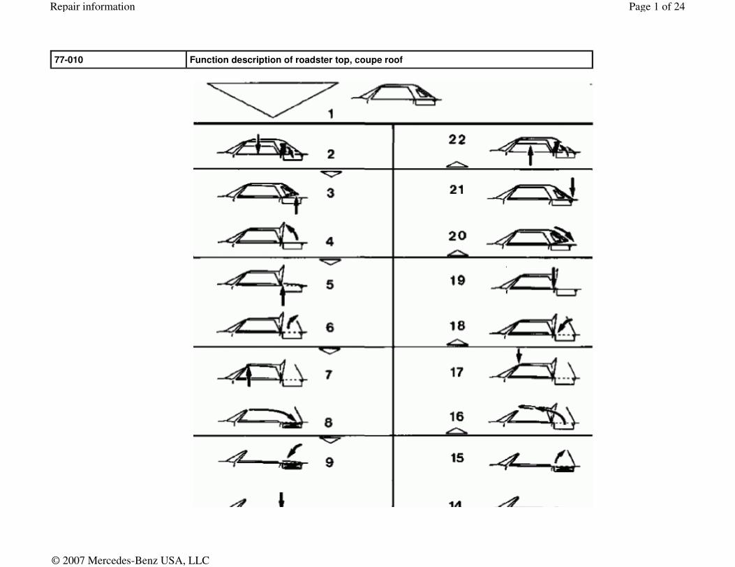
Opening top (automatic mode) Press top button! Closing top (automatic mode) Actuate top button!
1 top closed 12 top open
2 lower roll bar and side windows 13 lower roll bar and side windows
3 unlock cloth holding brace 14 unlock top compartment cover
4 push up cloth holding brace 15 open top compartment cover
5 unlock top compartment cover 16 close top
6 open top compartment cover 17 lock top
7 unlock top 18 close top compartment cover
8 open top 19 lock top compartment cover
9 close top compartment cover 20 pull down cloth holding brace
10 lock top compartment cover 21 lock cloth holding brace
11 put up roll bar and side windows 22 put up roll bar and side windows
General Roadster top, coupe roof Roadster top
The standard equipment for model 129 includes a hydraulically actuated roadster top and a coupe roof. The switch for opening and closing the top is located on the center console. The top can be opened within approx. 30 seconds and stored in the top compartment by pressing the switch toward the rear and holding in this position or removed from the top compartment and closed by pressing the switch toward the front and holding in this position (when closing it may be necessary to "help" slightly by manually guiding the front top frame into the initial catch on the front top locks). For this purpose roll down side windows and put down roll bar and return to initial position afterward. The top moves only as long as the switch is actuated. The motion can be interrupted at any desired point and then continued or reversed. During an interruption the top is locked hydraulically so that it cannot fall down. The lock is released when the ignition is switched off and the top can be moved freely. Five opening/closing operations are possible immediately one after another. More than five operations are not possible due to the thermic load on the pump and solenoid valves. Monitoring is accomplished by counting the switch-on time for the pump and solenoid valves. Prerequisites for actuating top
Page 2 of 24Repair information
© 2007 Mercedes-Benz USA, LLC
Location of electric components
- ignition switched on - vehicle standing still - battery voltage > 10 V - roll bar control unit must release top actuation - no malfunctions prohibiting top actuation stored in malfunction memory - limit switch signals from control unit recognized as logical - the maximum operating time must not be exceeded - removal of the coupe roof is possible only when the time after switching on the ignition is < 10 seconds
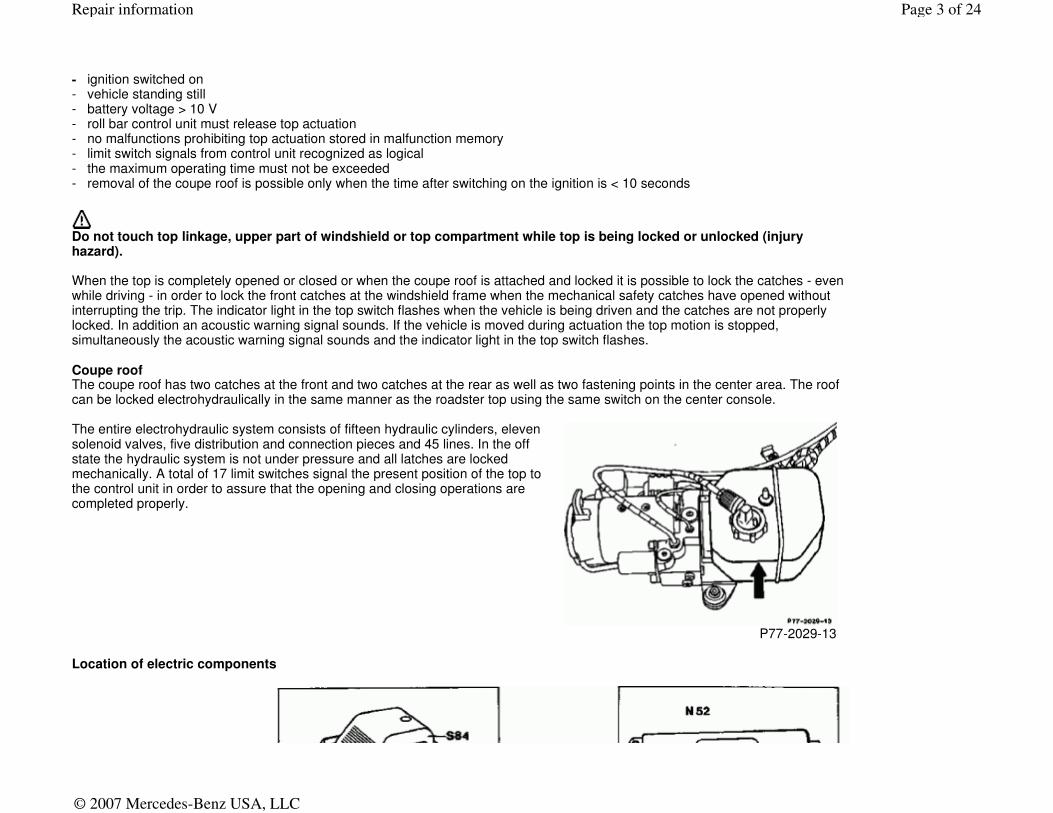
Do not touch top linkage, upper part of windshield or top compartment while top is being locked or unlocked (injury hazard). When the top is completely opened or closed or when the coupe roof is attached and locked it is possible to lock the catches - even while driving - in order to lock the front catches at the windshield frame when the mechanical safety catches have opened without interrupting the trip. The indicator light in the top switch flashes when the vehicle is being driven and the catches are not properly locked. In addition an acoustic warning signal sounds. If the vehicle is moved during actuation the top motion is stopped, simultaneously the acoustic warning signal sounds and the indicator light in the top switch flashes. Coupe roof The coupe roof has two catches at the front and two catches at the rear as well as two fastening points in the center area. The roof can be locked electrohydraulically in the same manner as the roadster top using the same switch on the center console.
The entire electrohydraulic system consists of fifteen hydraulic cylinders, eleven solenoid valves, five distribution and connection pieces and 45 lines. In the off state the hydraulic system is not under pressure and all latches are locked mechanically. A total of 17 limit switches signal the present position of the top to the control unit in order to assure that the opening and closing operations are completed properly.
P77-2029-13
Page 3 of 24Repair information
© 2007 Mercedes-Benz USA, LLC
P77-0069-59
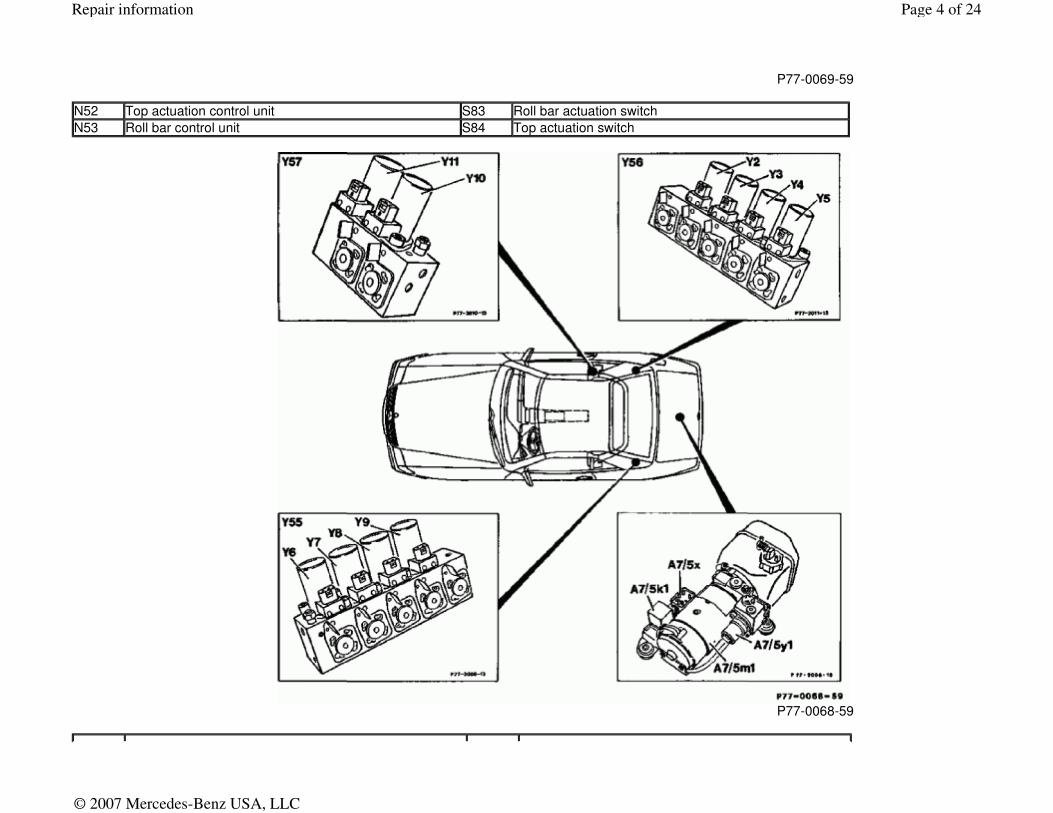
N52 Top actuation control unit S83 Roll bar actuation switch
N53 Roll bar control unit S84 Top actuation switch
P77-0068-59
Page 4 of 24Repair information
© 2007 Mercedes-Benz USA, LLC
A7/5 Hydraulic unit for top actuation (roll bar) Y55y9 Put down cloth holding brace
A7/5k1 Relay Y56 Valve block for top actuation, quadruple, right
A7/5m1 Motor Y56y2 Rear catches
A7/5x Plug connector Y56y3 Center catches
A7/5y1 Main valve Y56y4 Front catches
Y55 Valve block for top actuation, quadruple, left Y56y5 Top compartment cover
Y55y6 Open top Y57 Valve block for roll bar
Y55y7 Close top Y57y10 Rod side
Y55y8 Put up cloth holding brace Y57y11 Piston side
Page 5 of 24Repair information
© 2007 Mercedes-Benz USA, LLC
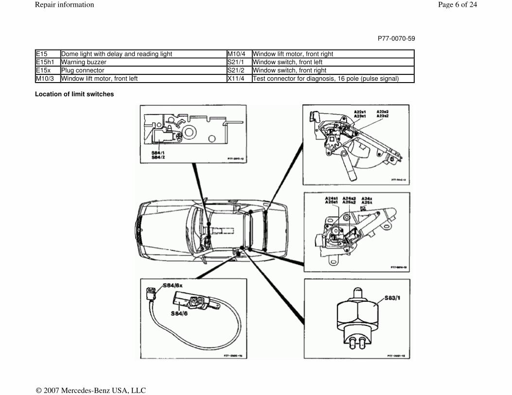
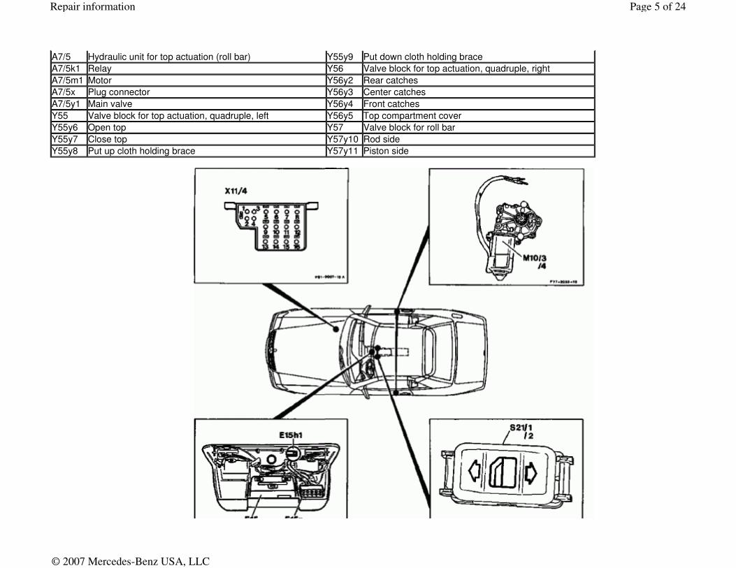
Location of limit switches
P77-0070-59
E15 Dome light with delay and reading light M10/4 Window lift motor, front right
E15h1 Warning buzzer S21/1 Window switch, front left
E15x Plug connector S21/2 Window switch, front right
M10/3 Window lift motor, front left X11/4 Test connector for diagnosis, 16 pole (pulse signal)
Page 6 of 24Repair information
© 2007 Mercedes-Benz USA, LLC
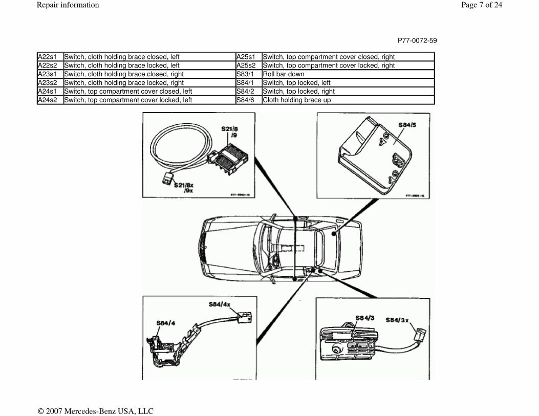
P77-0072-59
A22s1 Switch, cloth holding brace closed, left A25s1 Switch, top compartment cover closed, right
A22s2 Switch, cloth holding brace locked, left A25s2 Switch, top compartment cover locked, right
A23s1 Switch, cloth holding brace closed, right S83/1 Roll bar down
A23s2 Switch, cloth holding brace locked, right S84/1 Switch, top locked, left
A24s1 Switch, top compartment cover closed, left S84/2 Switch, top locked, right
A24s2 Switch, top compartment cover locked, left S84/6 Cloth holding brace up
Page 7 of 24Repair information
© 2007 Mercedes-Benz USA, LLC
P77-0071-59
S21/8 Limit switch, side window down, right
S21/9 Limit switch, side window down, left
S84/3 Top in top compartment
S84/4 Top up (differential operation)
S84/5 Top compartment cover open
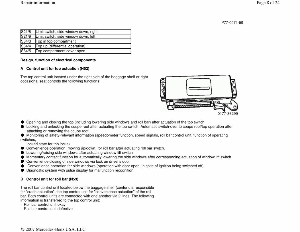
Design, function of electrical components A Control unit for top actuation (N52)
The top control unit located under the right side of the baggage shelf or right occasional seat controls the following functions:
0177-36299 ● Opening and closing the top (including lowering side windows and roll bar) after actuation of the top switch ● Locking and unlocking the coupe roof after actuating the top switch. Automatic switch-over to coupe roof/top operation after
attaching or removing the coupe roof ● Monitoring of safety-relevant information (speedometer function, speed signals, roll bar control unit, function of operating switches, locked state for top locks) ● Convenience operation (moving up/down) for roll bar after actuating roll bar switch. ● Lowering/raising side windows after actuating window lift switch ● Momentary contact function for automatically lowering the side windows after corresponding actuation of window lift switch ● Convenience closing of side windows via lock on driver's door ● Convenience operation for side windows (operation with door open, in spite of ignition being switched off). ● Diagnostic system with pulse display for malfunction recognition.
B Control unit for roll bar (N53)
The roll bar control unit located below the baggage shelf (center), is responsible for "crash actuation"; the top control unit for "convenience actuation" of the roll bar. Both control units are connected with one another via 2 lines. The following information is transferred to the top control unit: - Roll bar control unit okay - Roll bar control unit defective
Page 8 of 24Repair information
© 2007 Mercedes-Benz USA, LLC
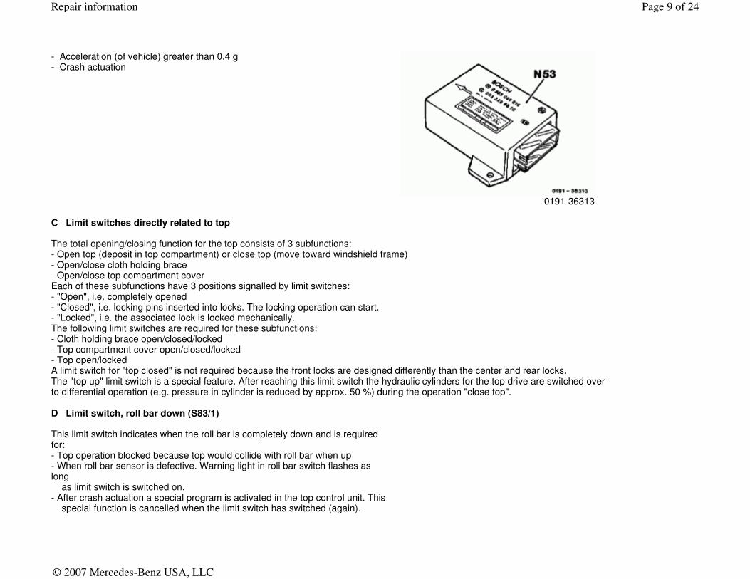
- Acceleration (of vehicle) greater than 0.4 g - Crash actuation
0191-36313
C Limit switches directly related to top The total opening/closing function for the top consists of 3 subfunctions: - Open top (deposit in top compartment) or close top (move toward windshield frame) - Open/close cloth holding brace - Open/close top compartment cover Each of these subfunctions have 3 positions signalled by limit switches: - "Open", i.e. completely opened - "Closed", i.e. locking pins inserted into locks. The locking operation can start. - "Locked", i.e. the associated lock is locked mechanically. The following limit switches are required for these subfunctions: - Cloth holding brace open/closed/locked - Top compartment cover open/closed/locked - Top open/locked A limit switch for "top closed" is not required because the front locks are designed differently than the center and rear locks. The "top up" limit switch is a special feature. After reaching this limit switch the hydraulic cylinders for the top drive are switched over to differential operation (e.g. pressure in cylinder is reduced by approx. 50 %) during the operation "close top". D Limit switch, roll bar down (S83/1)
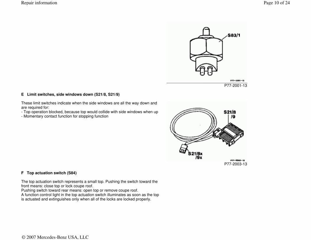
This limit switch indicates when the roll bar is completely down and is required for: - Top operation blocked because top would collide with roll bar when up - When roll bar sensor is defective. Warning light in roll bar switch flashes as long as limit switch is switched on. - After crash actuation a special program is activated in the top control unit. This special function is cancelled when the limit switch has switched (again).
Page 9 of 24Repair information
© 2007 Mercedes-Benz USA, LLC
P77-2001-13
E Limit switches, side windows down (S21/8, S21/9)
These limit switches indicate when the side windows are all the way down and are required for: - Top operation blocked, because top would collide with side windows when up - Momentary contact function for stopping function
P77-2003-13
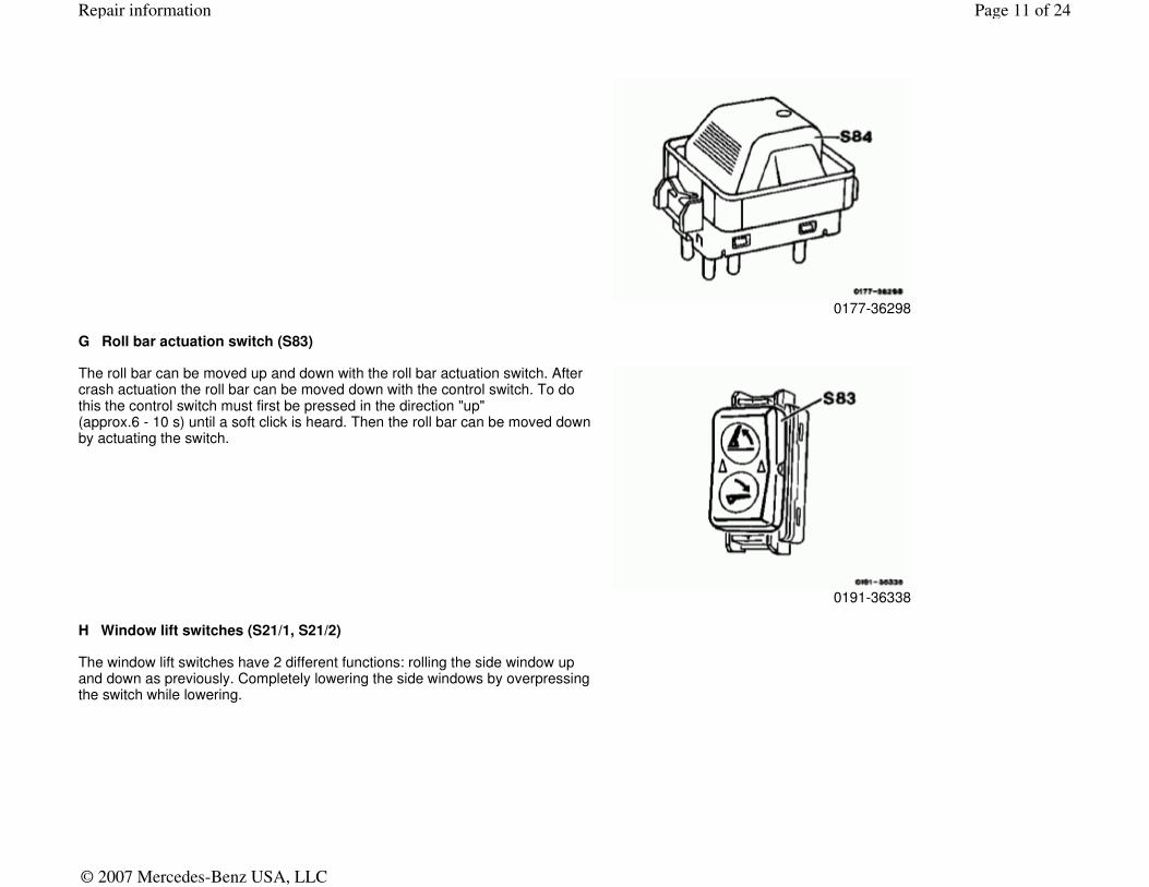
F Top actuation switch (S84)
The top actuation switch represents a small top. Pushing the switch toward the front means: close top or lock coupe roof. Pushing switch toward rear means: open top or remove coupe roof. A function control light in the top actuation switch illuminates as soon as the top is actuated and extinguishes only when all of the locks are locked properly.
Page 10 of 24Repair information
© 2007 Mercedes-Benz USA, LLC
0177-36298
G Roll bar actuation switch (S83)
The roll bar can be moved up and down with the roll bar actuation switch. After crash actuation the roll bar can be moved down with the control switch. To do this the control switch must first be pressed in the direction "up" (approx.6 - 10 s) until a soft click is heard. Then the roll bar can be moved down by actuating the switch.
0191-36338
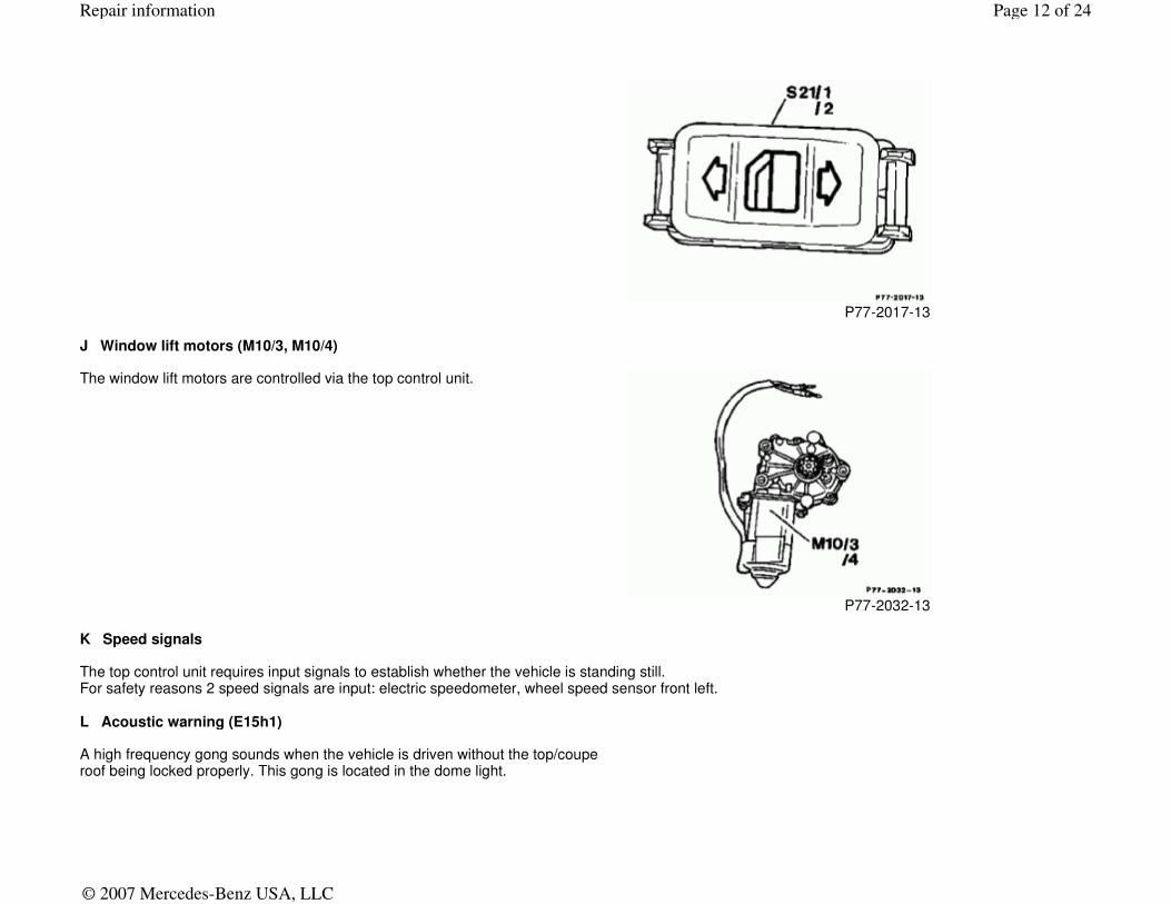
H Window lift switches (S21/1, S21/2)
The window lift switches have 2 different functions: rolling the side window up and down as previously. Completely lowering the side windows by overpressing the switch while lowering.
Page 11 of 24Repair information
© 2007 Mercedes-Benz USA, LLC
P77-2017-13
J Window lift motors (M10/3, M10/4)
The window lift motors are controlled via the top control unit.
P77-2032-13
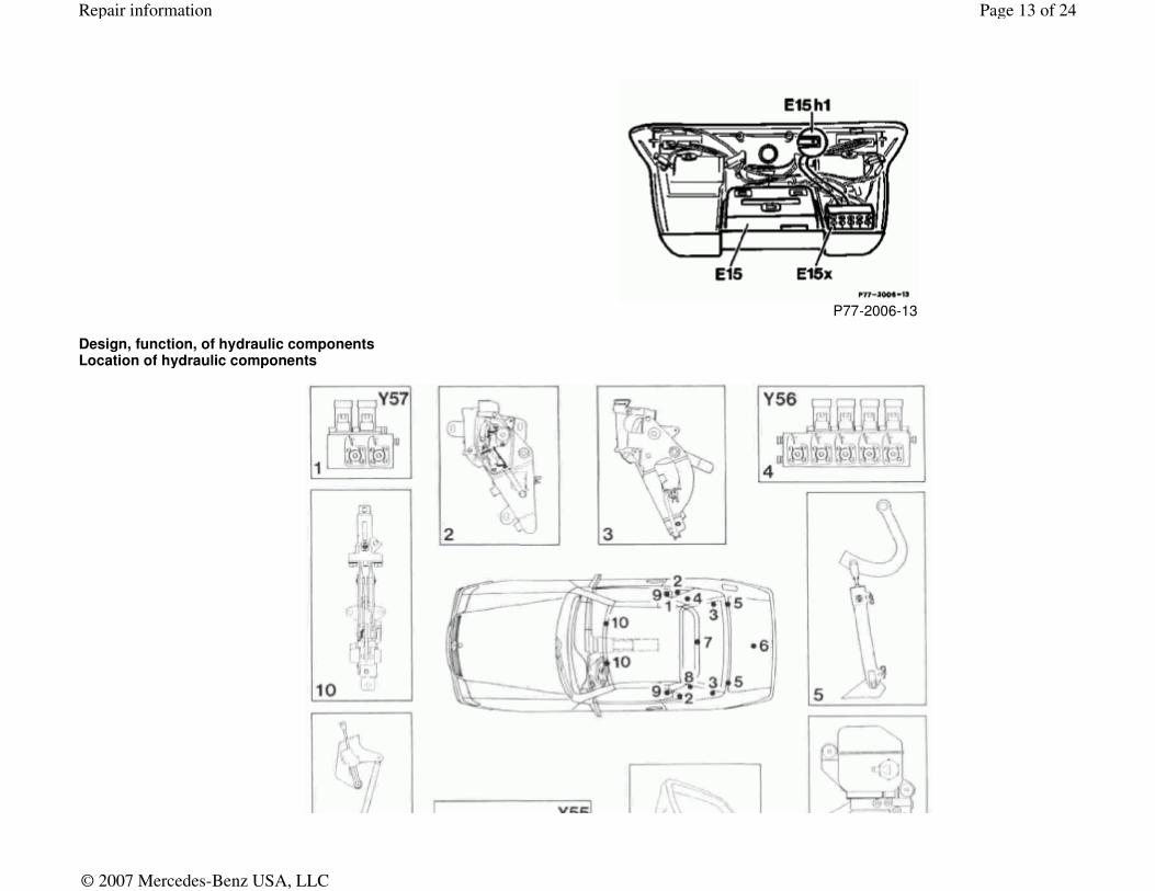
K Speed signals The top control unit requires input signals to establish whether the vehicle is standing still. For safety reasons 2 speed signals are input: electric speedometer, wheel speed sensor front left. L Acoustic warning (E15h1)
A high frequency gong sounds when the vehicle is driven without the top/coupe roof being locked properly. This gong is located in the dome light.
Page 12 of 24Repair information
© 2007 Mercedes-Benz USA, LLC
P77-2006-13
Design, function, of hydraulic components Location of hydraulic components
Page 13 of 24Repair information
© 2007 Mercedes-Benz USA, LLC
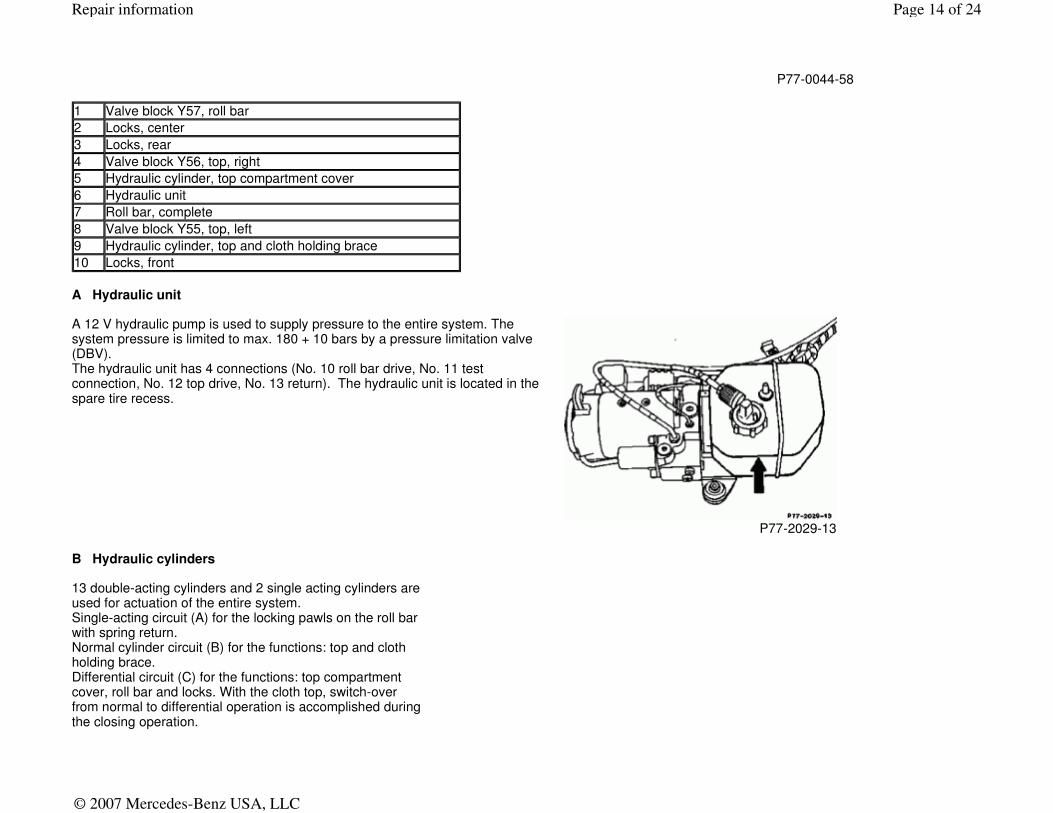
A Hydraulic unit
P77-0044-58
1 Valve block Y57, roll bar
2 Locks, center
3 Locks, rear
4 Valve block Y56, top, right
5 Hydraulic cylinder, top compartment cover
6 Hydraulic unit
7 Roll bar, complete
8 Valve block Y55, top, left
9 Hydraulic cylinder, top and cloth holding brace
10 Locks, front
A 12 V hydraulic pump is used to supply pressure to the entire system. The system pressure is limited to max. 180 + 10 bars by a pressure limitation valve (DBV). The hydraulic unit has 4 connections (No. 10 roll bar drive, No. 11 test connection, No. 12 top drive, No. 13 return). The hydraulic unit is located in the spare tire recess.
P77-2029-13
B Hydraulic cylinders
13 double-acting cylinders and 2 single acting cylinders are used for actuation of the entire system. Single-acting circuit (A) for the locking pawls on the roll bar with spring return. Normal cylinder circuit (B) for the functions: top and cloth holding brace. Differential circuit (C) for the functions: top compartment cover, roll bar and locks. With the cloth top, switch-over from normal to differential operation is accomplished during the closing operation.
Page 14 of 24Repair information
© 2007 Mercedes-Benz USA, LLC
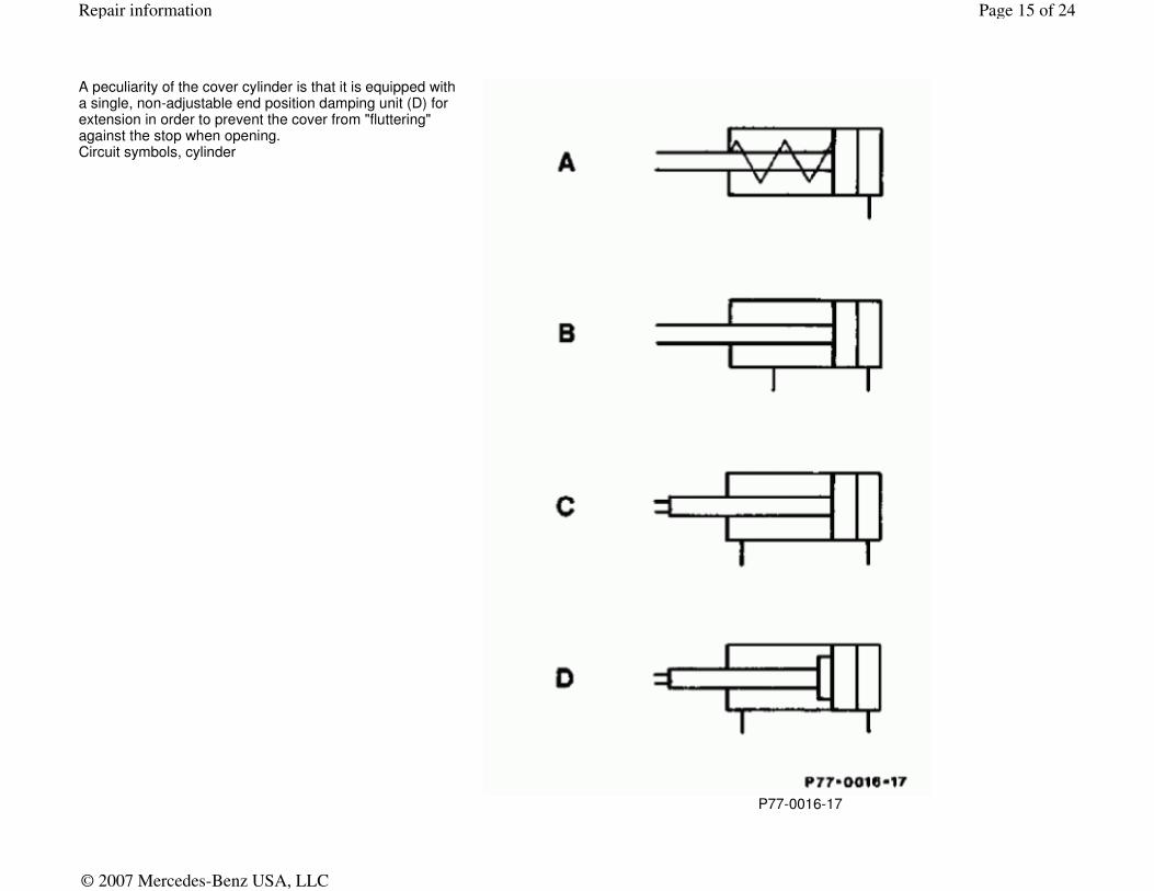
A peculiarity of the cover cylinder is that it is equipped with a single, non-adjustable end position damping unit (D) for extension in order to prevent the cover from "fluttering" against the stop when opening. Circuit symbols, cylinder
P77-0016-17
Page 15 of 24Repair information
© 2007 Mercedes-Benz USA, LLC
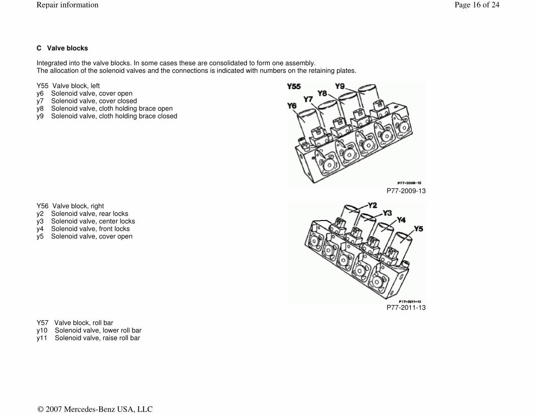
C Valve blocks Integrated into the valve blocks. In some cases these are consolidated to form one assembly. The allocation of the solenoid valves and the connections is indicated with numbers on the retaining plates.
Y55 Valve block, left y6 Solenoid valve, cover open y7 Solenoid valve, cover closed y8 Solenoid valve, cloth holding brace open y9 Solenoid valve, cloth holding brace closed
P77-2009-13
Y56 Valve block, right y2 Solenoid valve, rear locks y3 Solenoid valve, center locks y4 Solenoid valve, front locks y5 Solenoid valve, cover open
P77-2011-13
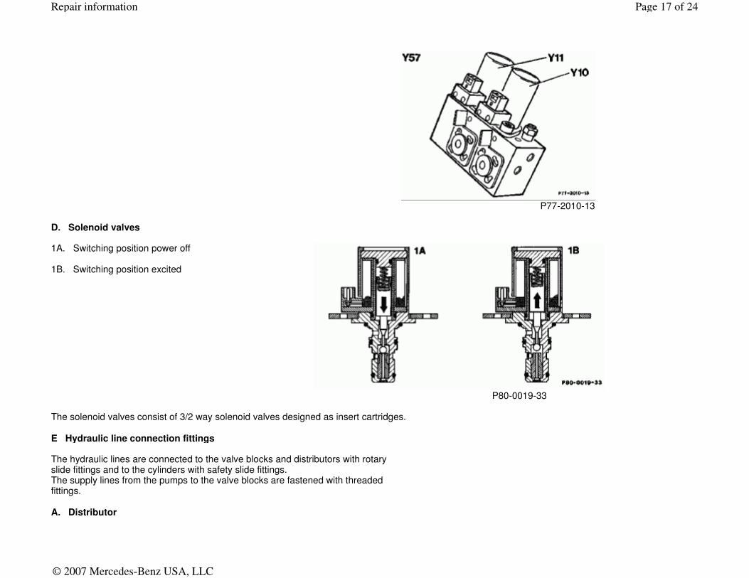
Y57 Valve block, roll bar y10 Solenoid valve, lower roll bar y11 Solenoid valve, raise roll bar
Page 16 of 24Repair information
© 2007 Mercedes-Benz USA, LLC
P77-2010-13
D. Solenoid valves
1A. Switching position power off 1B. Switching position excited
P80-0019-33
The solenoid valves consist of 3/2 way solenoid valves designed as insert cartridges. E Hydraulic line connection fittings
The hydraulic lines are connected to the valve blocks and distributors with rotary slide fittings and to the cylinders with safety slide fittings. The supply lines from the pumps to the valve blocks are fastened with threaded fittings. A. Distributor
Page 17 of 24Repair information
© 2007 Mercedes-Benz USA, LLC
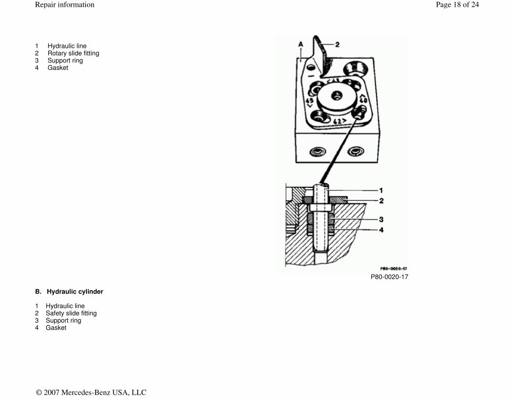
1 Hydraulic line 2 Rotary slide fitting 3 Support ring 4 Gasket
P80-0020-17
B. Hydraulic cylinder 1 Hydraulic line 2 Safety slide fitting 3 Support ring 4 Gasket
Page 18 of 24Repair information
© 2007 Mercedes-Benz USA, LLC
P80-0021-17
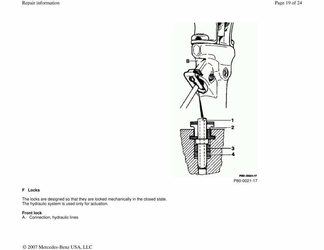
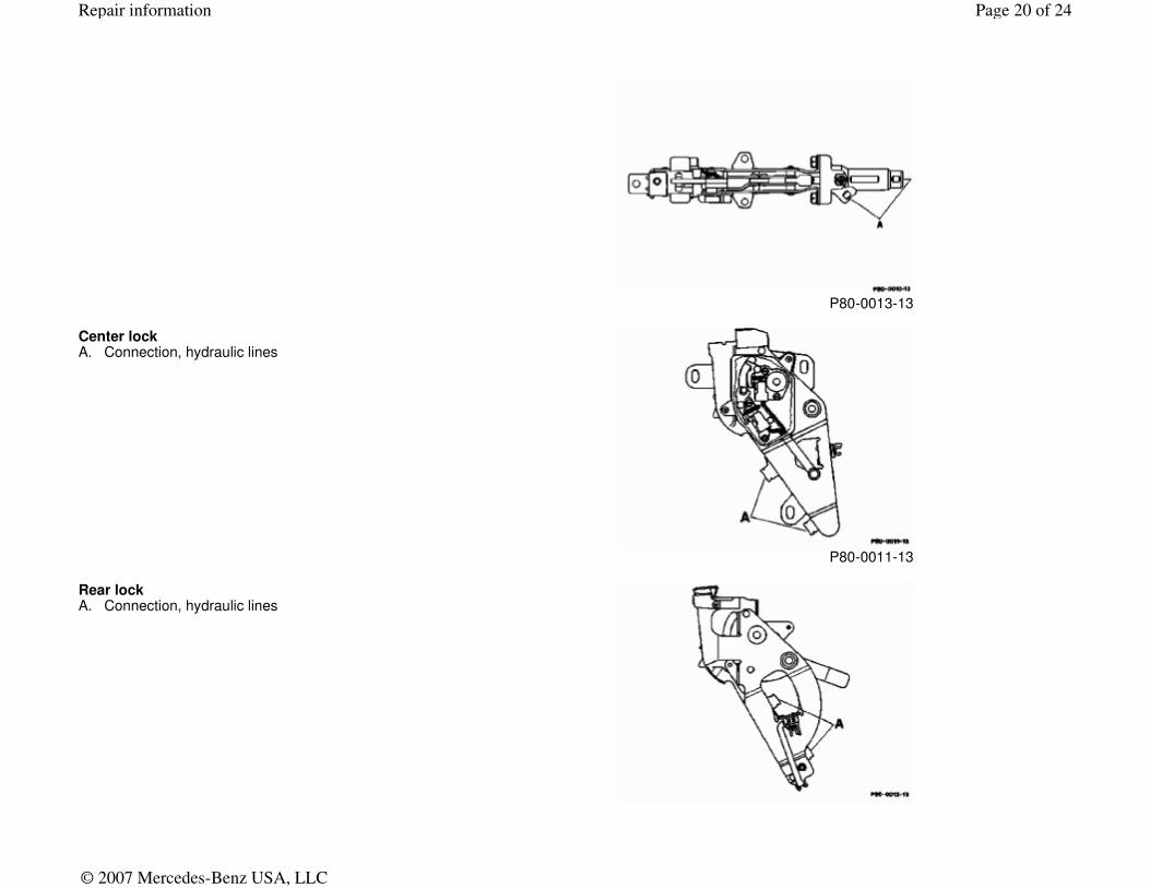
F Locks
The locks are designed so that they are locked mechanically in the closed state. The hydraulic system is used only for actuation. Front lock A. Connection, hydraulic lines
Page 19 of 24Repair information
© 2007 Mercedes-Benz USA, LLC
P80-0013-13
Center lock A. Connection, hydraulic lines
P80-0011-13
Rear lock A. Connection, hydraulic lines
Page 20 of 24Repair information
© 2007 Mercedes-Benz USA, LLC
P80-0012-13
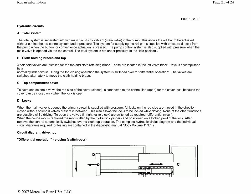
Hydraulic circuits A Total system The total system is separated into two main circuits by valve 1 (main valve) in the pump. This allows the roll bar to be actuated without putting the top control system under pressure. The system for supplying the roll bar is supplied with pressure directly from the pump when the button for convenience actuation is pressed. The pump control system is also supplied with pressure when the main valve is opened via the top control. The total system is not under pressure in the "idle position". B Cloth holding braces and top 4 solenoid valves are installed for the top and cloth retaining brace. These are located in the left valve block. Drive is accomplished by a normal cylinder circuit. During the top closing operation the system is switched over to "differential operation". The valves are switched alternately to move the cloth holding brace. C Top compartment cover To save one solenoid valve the rod side of the cover (closed) is connected to the control line (open) for the cover lock, because the cover can be closed only when the lock is open. D Locks When the main valve is opened the primary circuit is supplied with pressure. All locks on the rod side are moved in the direction closed without solenoid valves present in between. This also allows the locks to be locked while driving. None of the other functions are possible while driving. To open the valves (in right valve block) are switched as required (differential circuit). When the coupe roof is removed the roof is lifted by the hydraulic cylinders and positioned on a locked pawl of the lock. After removal the control automatically switches over to cloth top operation. The complete hydraulic circiut diagram and the individual circuit diagrams required for testing are contained in the diagnostic manual "Body Volume 1" 9.1.2. Circuit diagram, drive, top "Differential operation" - closing (switch-over)
Page 21 of 24Repair information
© 2007 Mercedes-Benz USA, LLC

Circuit diagram, drive, cloth holding brace "Stop function"
P77-0047-59
A. Solenoid valve No. 6 (excited)
B. Solenoid valve No. 7 (excited)
C. Hydraulic cylinder
D. Top frame
E. Valve block Y55
P. Pressure supply pump
R. Return
Page 22 of 24Repair information
© 2007 Mercedes-Benz USA, LLC
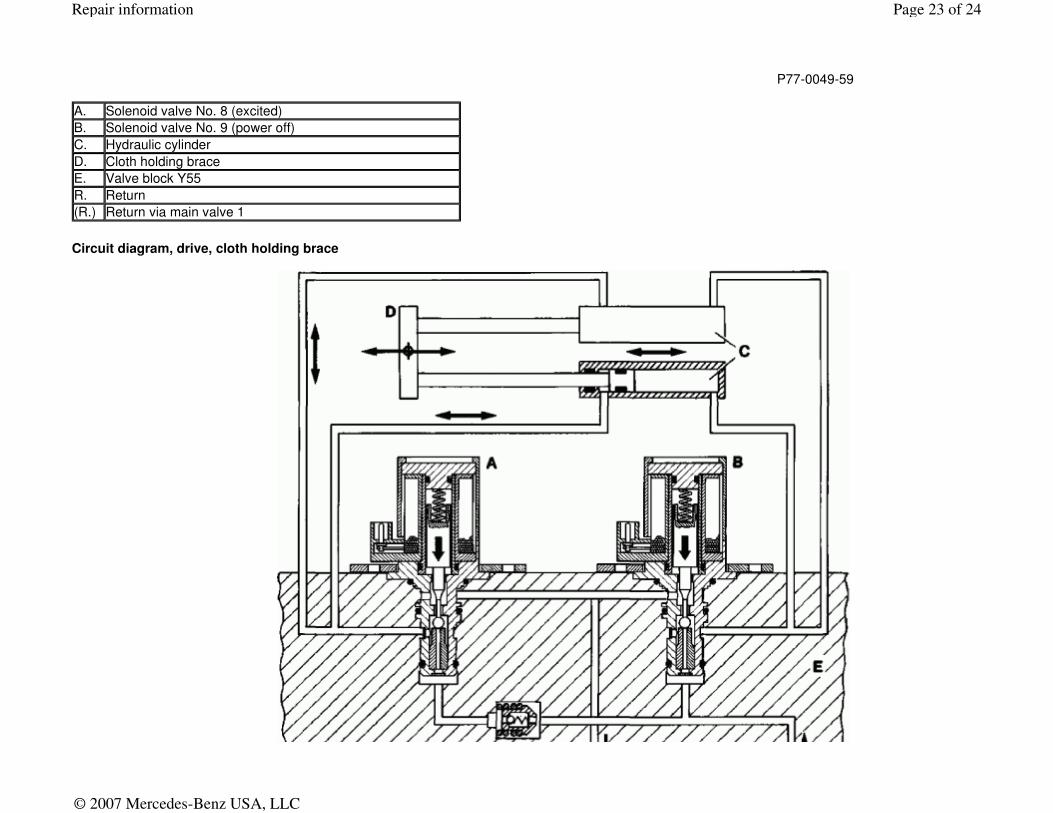
Circuit diagram, drive, cloth holding brace
P77-0049-59
A. Solenoid valve No. 8 (excited)
B. Solenoid valve No. 9 (power off)
C. Hydraulic cylinder
D. Cloth holding brace
E. Valve block Y55
R. Return
(R.) Return via main valve 1
Page 23 of 24Repair information
© 2007 Mercedes-Benz USA, LLC
P77-0048-59
A. Solenoid valve No. 8 (power off)
B. Solenoid valve No. 9 (power off)
C. Hydraulic cylinder
D. Cloth holding brace
E. Valve block Y55
P. Pressure supply pump
R. Return
Page 24 of 24Repair information
© 2007 Mercedes-Benz USA, LLC