© 2005 by Prentice Hall 1 Chapter 5: Logical Database Design and the Relational Model Modern...
58
© 2005 by Prentice Hall © 2005 by Prentice Hall 1 Chapter 5: Chapter 5: Logical Database Logical Database Design and the Design and the Relational Model Relational Model Modern Database Management Modern Database Management 7 7 th th Edition Edition Jeffrey A. Hoffer, Mary B. Prescott, Jeffrey A. Hoffer, Mary B. Prescott, Fred R. McFadden Fred R. McFadden
-
date post
19-Dec-2015 -
Category
Documents
-
view
218 -
download
0
Transcript of © 2005 by Prentice Hall 1 Chapter 5: Logical Database Design and the Relational Model Modern...

© 2005 by Prentice Hall© 2005 by Prentice Hall 11
Chapter 5:Chapter 5:Logical Database Design Logical Database Design and the Relational Modeland the Relational Model
Modern Database Modern Database ManagementManagement
77thth Edition EditionJeffrey A. Hoffer, Mary B. Prescott, Jeffrey A. Hoffer, Mary B. Prescott,
Fred R. McFaddenFred R. McFadden

22Chapter 5 © 2005 by Prentice Hall© 2005 by Prentice Hall
ObjectivesObjectives Definition of termsDefinition of terms List five properties of relationsList five properties of relations State two properties of candidate keysState two properties of candidate keys Define first, second, and third normal formDefine first, second, and third normal form Describe problems from merging relationsDescribe problems from merging relations Transform E-R and EER diagrams to Transform E-R and EER diagrams to
relationsrelations Create tables with entity and relational Create tables with entity and relational
integrity constraintsintegrity constraints Use normalization to convert anomalous Use normalization to convert anomalous
tables to well-structured relationstables to well-structured relations

33Chapter 5 © 2005 by Prentice Hall© 2005 by Prentice Hall
Maintenance
Purpose – information requirements structureDeliverable – detailed design specifications
Database activity – logical database design
Project Identification and Selection
Project Initiation and Planning
Analysis
Physical Design
Implementation
Maintenance
Logical DesignLogical Design
The Physical Design Stage of SDLC The Physical Design Stage of SDLC
(Figures 2-4, 2-5 revisited)(Figures 2-4, 2-5 revisited)

44Chapter 5 © 2005 by Prentice Hall© 2005 by Prentice Hall
RelationRelation Definition: A relation is a named, two-dimensional table Definition: A relation is a named, two-dimensional table
of data of data Table consists of rows (records), and columns (attribute Table consists of rows (records), and columns (attribute
or field)or field) Requirements for a table to qualify as a relation:Requirements for a table to qualify as a relation:
It must have a unique name.It must have a unique name. Every attribute value must be atomic (not multivalued, not Every attribute value must be atomic (not multivalued, not
composite)composite) Every row must be unique (can’t have two rows with exactly the Every row must be unique (can’t have two rows with exactly the
same values for all their fields)same values for all their fields) Attributes (columns) in tables must have unique namesAttributes (columns) in tables must have unique names The order of the columns must be irrelevantThe order of the columns must be irrelevant The order of the rows must be irrelevantThe order of the rows must be irrelevant
NOTE: all NOTE: all relationsrelations are in are in 11stst Normal form Normal form

55Chapter 5 © 2005 by Prentice Hall© 2005 by Prentice Hall
Correspondence with E-R Correspondence with E-R ModelModel
Relations (tables) correspond with entity types Relations (tables) correspond with entity types and with many-to-many relationship typesand with many-to-many relationship types
Rows correspond with entity instances and Rows correspond with entity instances and with many-to-many relationship instanceswith many-to-many relationship instances
Columns correspond with attributesColumns correspond with attributes
NOTE: The word NOTE: The word relationrelation (in relational (in relational database) is NOT the same as the word database) is NOT the same as the word relationshiprelationship (in E-R model) (in E-R model)

66Chapter 5 © 2005 by Prentice Hall© 2005 by Prentice Hall
Key FieldsKey Fields
Keys are special fields that serve two main Keys are special fields that serve two main purposes:purposes: Primary keysPrimary keys are are uniqueunique identifiers of the relation in identifiers of the relation in
question. Examples include employee numbers, social question. Examples include employee numbers, social security numbers, etc. security numbers, etc. This is how we can guarantee This is how we can guarantee that all rows are uniquethat all rows are unique
Foreign keysForeign keys are identifiers that enable a are identifiers that enable a dependentdependent relation (on the many side of a relationship) to refer to relation (on the many side of a relationship) to refer to its its parentparent relation (on the one side of the relationship) relation (on the one side of the relationship)
Keys can be Keys can be simplesimple (a single field) or (a single field) or compositecomposite (more than one field)(more than one field)
Keys usually are used as indexes to speed up the Keys usually are used as indexes to speed up the response to user queries (More on this in Ch. 6)response to user queries (More on this in Ch. 6)

77Chapter 5 © 2005 by Prentice Hall© 2005 by Prentice Hall
Primary Key
Foreign Key (implements 1:N relationship between customer and order)
Combined, these are a composite primary key (uniquely identifies the order line)…individually they are foreign keys (implement M:N relationship between order and product)
88Chapter 5 © 2005 by Prentice Hall© 2005 by Prentice Hall
Integrity ConstraintsIntegrity Constraints
Domain ConstraintsDomain Constraints Allowable values for an attribute. See Allowable values for an attribute. See
Table 5-1Table 5-1 Entity IntegrityEntity Integrity
No primary key attribute may be null. No primary key attribute may be null. All primary key fields All primary key fields MUSTMUST have data have data
Action AssertionsAction Assertions Business rules. Recall from Ch. 4Business rules. Recall from Ch. 4

99Chapter 5 © 2005 by Prentice Hall© 2005 by Prentice Hall
Domain definitions enforce domain integrity constraints

1010Chapter 5 © 2005 by Prentice Hall© 2005 by Prentice Hall
Integrity ConstraintsIntegrity Constraints
Referential Integrity – rule that states that any foreign Referential Integrity – rule that states that any foreign key value (on the relation of the many side) MUST match key value (on the relation of the many side) MUST match a primary key value in the relation of the one side. (Or a primary key value in the relation of the one side. (Or the foreign key can be null) the foreign key can be null) For example: Delete RulesFor example: Delete Rules
Restrict – don’t allow delete of “parent” side if related rows Restrict – don’t allow delete of “parent” side if related rows exist in “dependent” sideexist in “dependent” side
Cascade – automatically delete “dependent” side rows that Cascade – automatically delete “dependent” side rows that correspond with the “parent” side row to be deletedcorrespond with the “parent” side row to be deleted
Set-to-Null – set the foreign key in the dependent side to null if Set-to-Null – set the foreign key in the dependent side to null if deleting from the parent side deleting from the parent side not allowed for weak entities not allowed for weak entities

1111Chapter 5 © 2005 by Prentice Hall© 2005 by Prentice Hall
Figure 5-5: Referential integrity constraints (Pine Valley Furniture)
Referential integrity
constraints are drawn via arrows from dependent to
parent table

1212Chapter 5 © 2005 by Prentice Hall© 2005 by Prentice Hall
Referential integrity
constraints are implemented with
foreign key to primary key references
1313Chapter 5 © 2005 by Prentice Hall© 2005 by Prentice Hall
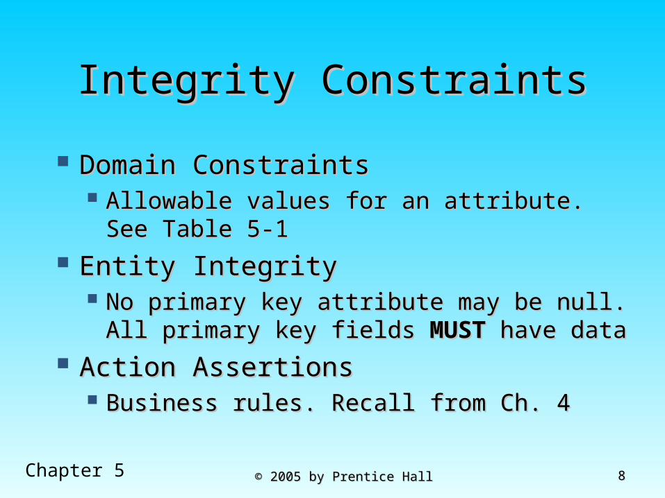
Transforming EER Diagrams Transforming EER Diagrams into Relationsinto Relations
Mapping Regular Entities to Relations Mapping Regular Entities to Relations 1.1. Simple attributes: E-R attributes map Simple attributes: E-R attributes map
directly onto the relationdirectly onto the relation
2.2. Composite attributes: Use only their Composite attributes: Use only their simple, component attributes simple, component attributes
3.3. Multivalued Attribute - Becomes a Multivalued Attribute - Becomes a separate relation with a foreign key separate relation with a foreign key taken from the superior entitytaken from the superior entity

1414Chapter 5 © 2005 by Prentice Hall© 2005 by Prentice Hall
(a) CUSTOMER entity type with simple attributes
Figure 5-8: Mapping a regular entity
(b) CUSTOMER relation
1515Chapter 5 © 2005 by Prentice Hall© 2005 by Prentice Hall
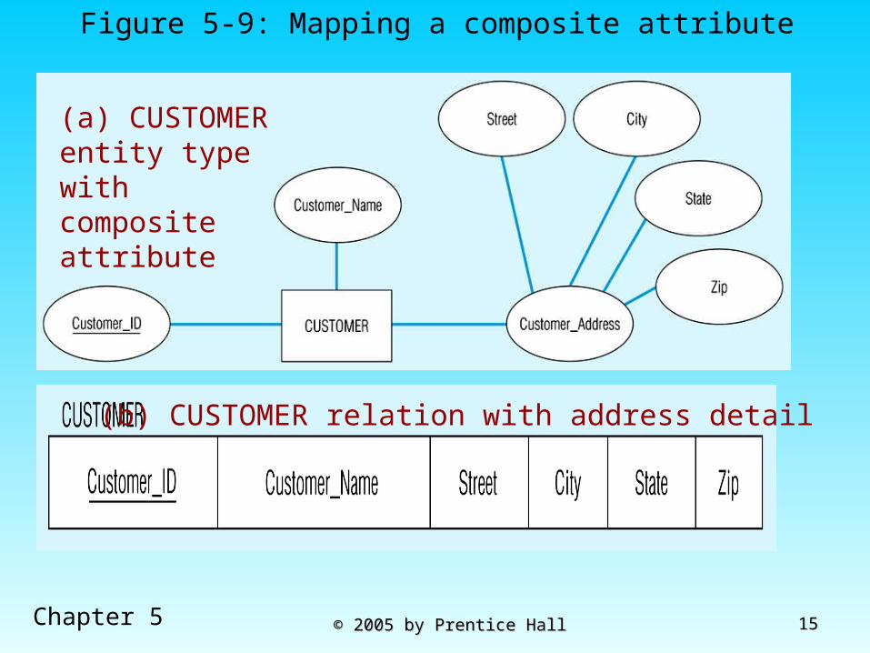
(a) CUSTOMER entity type with composite attribute
Figure 5-9: Mapping a composite attribute
(b) CUSTOMER relation with address detail

1616Chapter 5 © 2005 by Prentice Hall© 2005 by Prentice Hall
Figure 5-10: Mapping a multivalued attribute
1–to–many relationship between original entity and new relation
(a)
Multivalued attribute becomes a separate relation with foreign key
(b)

1717Chapter 5 © 2005 by Prentice Hall© 2005 by Prentice Hall
Transforming EER Diagrams Transforming EER Diagrams into Relations (cont.)into Relations (cont.)
Mapping Weak EntitiesMapping Weak Entities Becomes a separate relation with a Becomes a separate relation with a
foreign key taken from the superior foreign key taken from the superior entityentity
Primary key composed of:Primary key composed of: Partial identifier of weak entityPartial identifier of weak entity Primary key of identifying relation Primary key of identifying relation
(strong entity)(strong entity)

1818Chapter 5 © 2005 by Prentice Hall© 2005 by Prentice Hall

1919Chapter 5 © 2005 by Prentice Hall© 2005 by Prentice Hall
NOTE: the domain constraint for the foreign key should NOT allow null value if DEPENDENT is a weak entity
Foreign key
Composite primary key

2020Chapter 5 © 2005 by Prentice Hall© 2005 by Prentice Hall
Transforming EER Diagrams Transforming EER Diagrams into Relations (cont.)into Relations (cont.)
Mapping Binary RelationshipsMapping Binary Relationships One-to-Many - Primary key on the one side One-to-Many - Primary key on the one side
becomes a foreign key on the many sidebecomes a foreign key on the many side Many-to-Many - Create a Many-to-Many - Create a new relationnew relation
with the primary keys of the two entities with the primary keys of the two entities as its primary keyas its primary key
One-to-One - Primary key on the One-to-One - Primary key on the mandatory side becomes a foreign key on mandatory side becomes a foreign key on the optional sidethe optional side

2121Chapter 5 © 2005 by Prentice Hall© 2005 by Prentice Hall
Figure 5-12a: Example of mapping a 1:M relationshipRelationship between customers and orders
Note the mandatory one

2222Chapter 5 © 2005 by Prentice Hall© 2005 by Prentice Hall
Figure 5-12b Mapping the relationship
Again, no null value in the foreign key…this is because of the mandatory minimum cardinality
Foreign key

2323Chapter 5 © 2005 by Prentice Hall© 2005 by Prentice Hall
Figure 5-13a: Example of mapping an M:N relationshipE-R diagram (M:N)
The Supplies relationship will need to become a separate relation
2424Chapter 5 © 2005 by Prentice Hall© 2005 by Prentice Hall
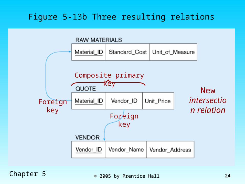
Figure 5-13b Three resulting relations
New intersection
relationForeign key
Foreign key
Composite primary key

2525Chapter 5 © 2005 by Prentice Hall© 2005 by Prentice Hall
Figure 5-14a: Mapping a binary 1:1 relationshipIn_charge relationship

2626Chapter 5 © 2005 by Prentice Hall© 2005 by Prentice Hall
Figure 5-14b Resulting relations

2727Chapter 5 © 2005 by Prentice Hall© 2005 by Prentice Hall
Transforming EER Diagrams Transforming EER Diagrams into Relations (cont.)into Relations (cont.)
Mapping Associative EntitiesMapping Associative Entities Identifier Not Assigned Identifier Not Assigned
Default primary key for the Default primary key for the association relation is composed of association relation is composed of the primary keys of the two entities the primary keys of the two entities (as in M:N relationship)(as in M:N relationship)
Identifier Assigned Identifier Assigned It is natural and familiar to end-usersIt is natural and familiar to end-users Default identifier may not be uniqueDefault identifier may not be unique

2828Chapter 5 © 2005 by Prentice Hall© 2005 by Prentice Hall

2929Chapter 5 © 2005 by Prentice Hall© 2005 by Prentice Hall

3030Chapter 5 © 2005 by Prentice Hall© 2005 by Prentice Hall
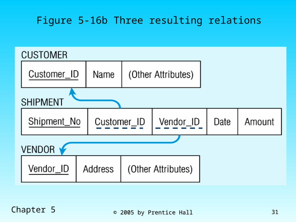
Figure 5-16a: Mapping an associative entity with an identifierAssociative entity
3131Chapter 5 © 2005 by Prentice Hall© 2005 by Prentice Hall
Figure 5-16b Three resulting relations

3232Chapter 5 © 2005 by Prentice Hall© 2005 by Prentice Hall
Transforming EER Diagrams Transforming EER Diagrams into Relations (cont.)into Relations (cont.)
Mapping Unary RelationshipsMapping Unary Relationships One-to-Many - Recursive foreign key in One-to-Many - Recursive foreign key in
the same relationthe same relation Many-to-Many - Two relations:Many-to-Many - Two relations:
One for the entity typeOne for the entity type One for an associative relation in which One for an associative relation in which
the primary key has two attributes, the primary key has two attributes, both taken from the primary key of the both taken from the primary key of the entityentity

3333Chapter 5 © 2005 by Prentice Hall© 2005 by Prentice Hall
Figure 5-17: Mapping a unary 1:N relationship
(a) EMPLOYEE entity with Manages relationship
(b) EMPLOYEE relation with recursive foreign key

3434Chapter 5 © 2005 by Prentice Hall© 2005 by Prentice Hall
Figure 5-18: Mapping a unary M:N relationship
(a) Bill-of-materials relationships (M:N)
(b) ITEM and COMPONENT relations

3535Chapter 5 © 2005 by Prentice Hall© 2005 by Prentice Hall
Transforming EER Diagrams Transforming EER Diagrams into Relations (cont.)into Relations (cont.)
Mapping Ternary (and n-ary) Mapping Ternary (and n-ary) RelationshipsRelationships One relation for each entity and One relation for each entity and
one for the associative entityone for the associative entity Associative entity has foreign keys Associative entity has foreign keys
to each entity in the relationshipto each entity in the relationship

3636Chapter 5 © 2005 by Prentice Hall© 2005 by Prentice Hall
Figure 5-19a: Mapping a ternary relationshipTernary relationship with associative entity

3737Chapter 5 © 2005 by Prentice Hall© 2005 by Prentice Hall
Figure 5-19b Mapping the ternary relationship
Remember that the primary key MUST be
unique
3838Chapter 5 © 2005 by Prentice Hall© 2005 by Prentice Hall
Transforming EER Transforming EER Diagrams into Relations Diagrams into Relations
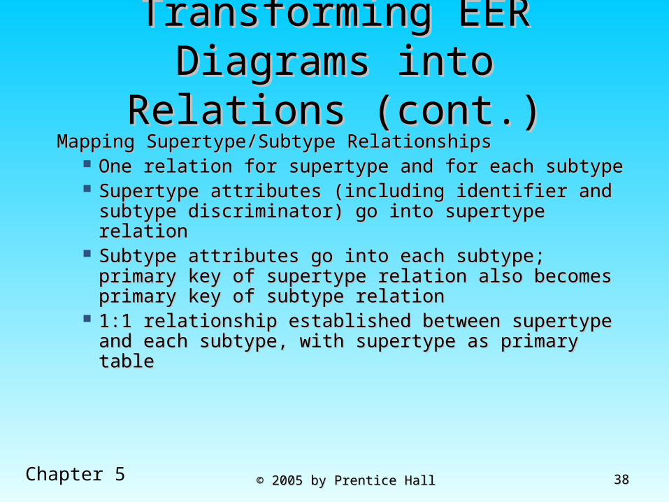
(cont.)(cont.)Mapping Supertype/Subtype RelationshipsMapping Supertype/Subtype Relationships
One relation for supertype and for each subtypeOne relation for supertype and for each subtype Supertype attributes (including identifier and Supertype attributes (including identifier and
subtype discriminator) go into supertype relationsubtype discriminator) go into supertype relation Subtype attributes go into each subtype; primary Subtype attributes go into each subtype; primary
key of supertype relation also becomes primary key of supertype relation also becomes primary key of subtype relationkey of subtype relation
1:1 relationship established between supertype 1:1 relationship established between supertype and each subtype, with supertype as primary and each subtype, with supertype as primary tabletable

3939Chapter 5 © 2005 by Prentice Hall© 2005 by Prentice Hall
Figure 5-20: Supertype/subtype relationships

4040Chapter 5 © 2005 by Prentice Hall© 2005 by Prentice Hall
Figure 5-21: Mapping Supertype/subtype relationships to relations
These are implemented as one-to-one relationships

4141Chapter 5 © 2005 by Prentice Hall© 2005 by Prentice Hall
Data NormalizationData Normalization Primarily a tool to validate and Primarily a tool to validate and
improve a logical design so that it improve a logical design so that it satisfies certain constraints that satisfies certain constraints that avoid unnecessary avoid unnecessary duplication of dataduplication of data
The process of decomposing The process of decomposing relations with anomalies to produce relations with anomalies to produce smaller, smaller, well-structuredwell-structured relationsrelations

4242Chapter 5 © 2005 by Prentice Hall© 2005 by Prentice Hall
Well-Structured RelationsWell-Structured Relations A relation that contains minimal data redundancy A relation that contains minimal data redundancy
and allows users to insert, delete, and update and allows users to insert, delete, and update rows without causing data inconsistenciesrows without causing data inconsistencies
Goal is to avoid anomaliesGoal is to avoid anomalies Insertion AnomalyInsertion Anomaly – adding new rows forces user to – adding new rows forces user to
create duplicate datacreate duplicate data Deletion AnomalyDeletion Anomaly – deleting rows may cause a loss of – deleting rows may cause a loss of
data that would be needed for other future rowsdata that would be needed for other future rows Modification AnomalyModification Anomaly – changing data in a row – changing data in a row
forces changes to other rows because of duplicationforces changes to other rows because of duplication
General rule of thumb: a table should not pertain to more than one entity type

4343Chapter 5 © 2005 by Prentice Hall© 2005 by Prentice Hall
Example – Figure 5.2bExample – Figure 5.2b
Question – Is this a relation? Answer – Yes: unique rows and no multivalued attributes
Question – What’s the primary key? Answer – Composite: Emp_ID, Course_Title

4444Chapter 5 © 2005 by Prentice Hall© 2005 by Prentice Hall
Anomalies in this TableAnomalies in this Table InsertionInsertion – can’t enter a new employee without – can’t enter a new employee without
having the employee take a classhaving the employee take a class DeletionDeletion – if we remove employee 140, we lose – if we remove employee 140, we lose
information about the existence of a Tax Acc information about the existence of a Tax Acc classclass
ModificationModification – giving a salary increase to – giving a salary increase to employee 100 forces us to update multiple employee 100 forces us to update multiple recordsrecordsWhy do these anomalies exist?
Because there are two themes (entity types) into one relation. This results in duplication, and an unnecessary dependency between the entities

4545Chapter 5 © 2005 by Prentice Hall© 2005 by Prentice Hall
Functional Dependencies and Functional Dependencies and KeysKeys
Functional Dependency: The value of one Functional Dependency: The value of one attribute (the attribute (the determinantdeterminant) determines ) determines the value of another attributethe value of another attribute
Candidate Key:Candidate Key: A unique identifier. One of the candidate A unique identifier. One of the candidate
keys will become the primary keykeys will become the primary key E.g. perhaps there is both credit card number and E.g. perhaps there is both credit card number and
SS# in a table…in this case both are candidate SS# in a table…in this case both are candidate keyskeys
Each non-key field is functionally dependent Each non-key field is functionally dependent on every candidate keyon every candidate key

4646Chapter 5 © 2005 by Prentice Hall© 2005 by Prentice Hall
Figure 5.22 -Steps in normalization

4747Chapter 5 © 2005 by Prentice Hall© 2005 by Prentice Hall
First Normal FormFirst Normal Form No multivalued attributesNo multivalued attributes Every attribute value is atomicEvery attribute value is atomic Fig. 5-25 Fig. 5-25 is notis not in 1 in 1stst Normal Form Normal Form
(multivalued attributes) (multivalued attributes) it is not a it is not a relationrelation
Fig. 5-26 Fig. 5-26 isis in 1 in 1stst Normal form Normal form All relationsAll relations are in 1 are in 1stst Normal Form Normal Form

4848Chapter 5 © 2005 by Prentice Hall© 2005 by Prentice Hall
Table with multivalued attributes, not in 1st normal form
Note: this is NOT a relation

4949Chapter 5 © 2005 by Prentice Hall© 2005 by Prentice Hall
Table with no multivalued attributes and unique rows, in 1st normal form
Note: this is relation, but not a well-structured one

5050Chapter 5 © 2005 by Prentice Hall© 2005 by Prentice Hall
Anomalies in this TableAnomalies in this Table InsertionInsertion – if new product is ordered for – if new product is ordered for
order 1007 of existing customer, customer order 1007 of existing customer, customer data must be re-entered, causing duplicationdata must be re-entered, causing duplication
DeletionDeletion – if we delete the Dining Table from – if we delete the Dining Table from Order 1006, we lose information concerning Order 1006, we lose information concerning this item's finish and pricethis item's finish and price
UpdateUpdate – changing the price of product ID 4 – changing the price of product ID 4 requires update in several recordsrequires update in several records
Why do these anomalies exist? Because there are multiple themes (entity types) into one relation. This results in duplication, and an unnecessary dependency between the entities

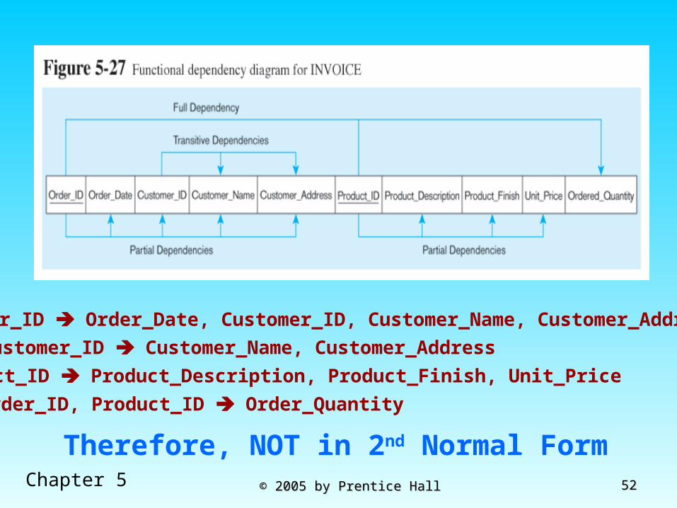
5151Chapter 5 © 2005 by Prentice Hall© 2005 by Prentice Hall
Second Normal FormSecond Normal Form 1NF PLUS 1NF PLUS every non-key every non-key
attribute is fully functionally attribute is fully functionally dependent on the ENTIRE dependent on the ENTIRE primary keyprimary key Every non-key attribute must be Every non-key attribute must be
defined by the entire key, not by only defined by the entire key, not by only part of the keypart of the key
No partial functional dependenciesNo partial functional dependencies
5252Chapter 5 © 2005 by Prentice Hall© 2005 by Prentice Hall
Order_ID Order_Date, Customer_ID, Customer_Name, Customer_Address
Therefore, NOT in 2nd Normal Form
Customer_ID Customer_Name, Customer_Address
Product_ID Product_Description, Product_Finish, Unit_Price
Order_ID, Product_ID Order_Quantity
5353Chapter 5 © 2005 by Prentice Hall© 2005 by Prentice Hall
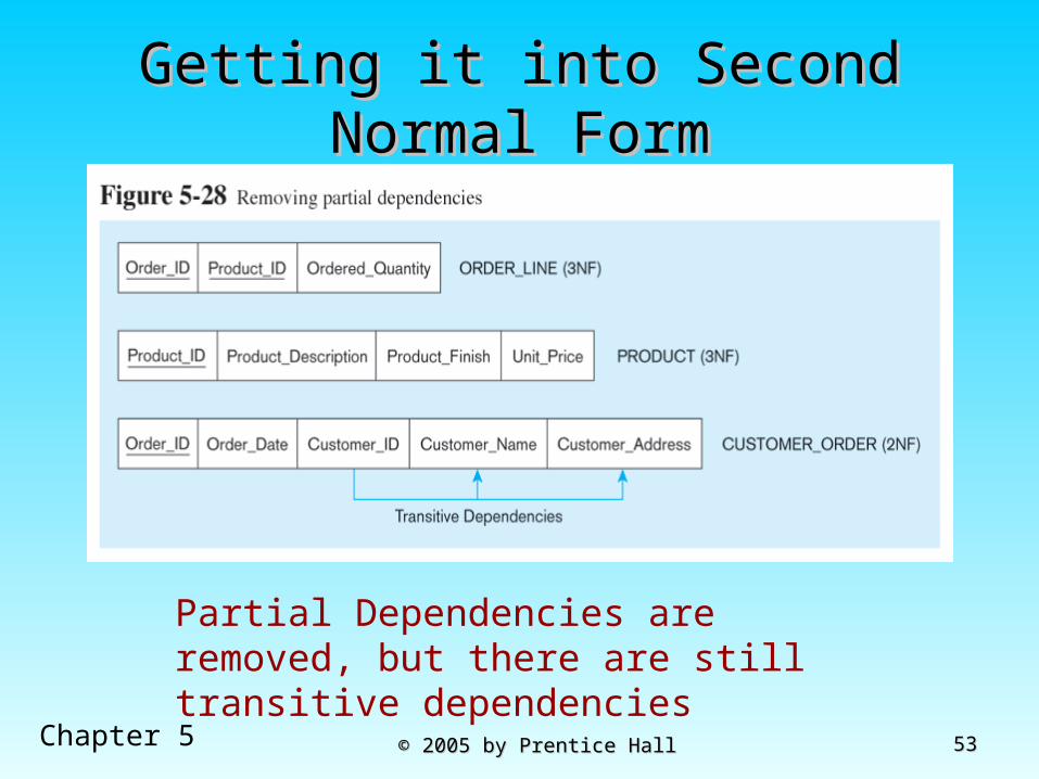
Getting it into Second Normal Getting it into Second Normal FormForm
Partial Dependencies are removed, but there are still transitive dependencies

5454Chapter 5 © 2005 by Prentice Hall© 2005 by Prentice Hall
Third Normal FormThird Normal Form 2NF PLUS 2NF PLUS no transitive dependenciesno transitive dependencies
(functional dependencies on non-primary-key (functional dependencies on non-primary-key attributes)attributes)
Note: this is called transitive, because the Note: this is called transitive, because the primary key is a determinant for another primary key is a determinant for another attribute, which in turn is a determinant for a attribute, which in turn is a determinant for a thirdthird
Solution: non-key determinant with transitive Solution: non-key determinant with transitive dependencies go into a new table; non-key dependencies go into a new table; non-key determinant becomes primary key in the new determinant becomes primary key in the new table and stays as foreign key in the old table and stays as foreign key in the old table table

5555Chapter 5 © 2005 by Prentice Hall© 2005 by Prentice Hall
Getting it into Third Normal Getting it into Third Normal FormForm
Transitive dependencies are removed

5656Chapter 5 © 2005 by Prentice Hall© 2005 by Prentice Hall
Merging RelationsMerging Relations View Integration – Combining entities from View Integration – Combining entities from
multiple ER models into common relationsmultiple ER models into common relations Issues to watch out for when merging entities Issues to watch out for when merging entities
from different ER models:from different ER models: Synonyms – two or more attributes with different Synonyms – two or more attributes with different
names but same meaningnames but same meaning Homonyms – attributes with same name but Homonyms – attributes with same name but
different meaningsdifferent meanings Transitive dependencies – even if relations are in Transitive dependencies – even if relations are in
3NF prior to merging, they may not be after merging3NF prior to merging, they may not be after merging Supertype/subtype relationships – may be hidden Supertype/subtype relationships – may be hidden
prior to mergingprior to merging
5757Chapter 5 © 2005 by Prentice Hall© 2005 by Prentice Hall
Enterprise KeysEnterprise Keys
Primary keys that are unique in the whole Primary keys that are unique in the whole database, not just within a single relationdatabase, not just within a single relation
Corresponds with the concept of an object Corresponds with the concept of an object ID in object-oriented systemsID in object-oriented systems

5858Chapter 5 © 2005 by Prentice Hall© 2005 by Prentice Hall