IQIufdcimages.uflib.ufl.edu/UF/00/02/62/87/00001/00001.pdf · 2005. 6. 16. · IQI ... iqi

'*-13 692 CONIUSTION STUDIES OF ACOUSTIC LSENDDL IQI
DROPETS(U) AY BALLISTIC RESEARCH LAB ABERDEENPROVING GROUND MD MAR 88 BRL-CR-594
INCLASSIFIED F/G 20/1 ML
El/Im///Eml/iKEIIIIEIIEIIEEEllllllll

111111111:66I~w~~1
MICROCOPY RESOLUTION TEST CHART
FR #A, wA~ 1 013

& BRL 1938 - Serving the Army for Fifty Years - 1988
El RT L
0COMBUSTION STUDIES OF ACOUSTICALLY(SUSPENDED LIQUID DROPLETS
DEPT. OF MECHANICAL ENGINEERINGCORVALLIS, OR 97331
DTICELECTE
MARCH 1988AP25M
APPROVED FOR PUBLIC RELEASE, DISTRIBUTION UNLIMITED -
U.S. ARMY LABORATORY COMMAND
BALLISTIC RESEARCH LABORATORY
ABERDEEN PROVING GROUND, MARYLAND
88 4 25 100

UNCLASSIFIED
:-CuRITY CLASSIFICATION OF THIS PAGE
REPORT DOCUMENTATION PAGE OMB No. 7o001
REPORT SECURITY CLASSIFICATION I b-,K. CLASSIFICATION AUTHORITY 3 DISTRIBUTION/AVAILABILITY OF REPORT
Approved for Public Release; Distribution. 'ASC rCO(TION/DOWNGRADING SCHEDULE Unlimited.
- ORGAN:ZATION REPORT NUMBER(S) S MONITORING ORGANIZATION REPORT NUMBER(S)
Svery Order 0430 BRL-CR-594
\AviE Or PERFORMING ORGANIZATION 6b. OFFICE SYMBOL 7a. NAME OF MONITORING ORGANIZATION(if applicable)
, egon State University US Army Research Office
0 R E.SS (City, Stote, and ZIP Code) 7b ADDRESS (City, State, and ZIP Code)
),pt. of Mechanical Engineering P.O. Box 12211
>rvallis, OR 97331 Research Triangle Park, NC 27709-2211
NAVE OF FUNDING ISPONSORING b. OFFICE SYMBOL 9. PROCUREMENT INSTRUMENT IDENTIFICATION NUMBERGAGANZATION (If applicable)
.allistic Research Laboratory I SLCBR-IBADDRESS (City, State, and ZIP Code) 10. SOURCE OF FUNDING NUMBERS
Aberdeen Proving Ground, MD 21005-5066 PROGRAM 'PROJECT ITASK jWORK UNIT
ELEMENT NO. NO. NO. CESSION NO.
TITLE (Include Security Classification)
COMBUSTION STUDIES OF ACOUSTICALLY SUSPENDED LIQUID DROPLETS
IcRSONAL AUTHOR(S)Richard B,. Peterson
TYPE OF REPORT 13b TIME COVERED 14. DATE OF REPORT (Year, Aon A ODy) 15. PAGE COUNT_,_ R FROM TO 30 Rap 44. .VNTARY NOTATION
Task was performed under a Scientific Services Agreement issued by Battelle, Research!_4ianye Par 0fie 20 akDie .. B 127. Research Triangle Park. NC 27709
SCOSATI CO DES Jla SUBJECT TERMS (Continue on reverse if necessary and identify by block number)
FIELD GROUP sUBU-GOUP -_Ultrasonic Resonator", 2 1 02 J Acoustic Levitation.'
ABSTRACT (Continue on reverse if necessary and identify by block number)
piezoelectrically driven ultrasonic resonator was developed and tested in this study. The
device was used to levitate liquid fuel droplets for evaporation measurements and ignition:tudies. The final report describes the resonator and its operating characteristics, gives
brief review of the literature, and presents the results of various ignition tests. Noliccessful minimum perturbation ignition method was discovered among the several explored.t is the author's opinion that the acoustic levitation technique may hold some promise foronducting non-combustion related droplet measurements, for example evaporation tests, butwIthout further development of the technique combustion experiments will be difficult to be
accopllsed.Minimum developmental needs will be for a high temperature, high pressureThamber and a feedback positioning controller. However, even with such additional featuresthere is some doubt whether stable levitation of a burning droplet can occur. I
.- STRISUTION/AVAILABILITY OF ABSTRACT 121 ABSTRACT SECURITY CLASSIFICATIONC1 UNCLASSIFIEDIUNLIMITED SAME AS RPT 0- DTIC USERS I Unclassified
22 a NAME OF RESPONSIBLE INDIVIDUAL |22b TELEPHONE (Include Area Code) 22c. OFFICE SYMBOL
DO Form 1473. JUN 86 Previous editions are obsolete. , SECUVRITY CLASSIFIC ATION OF THIS PAGE!Jl
UNCLASSIFIED

Jp71rw-
TABLE OF CONTENTS
Page
LIST OF FIGURES................................................... 5
SUMM4ARY........................................................... 7
I. INTRODUCTION ..................................................o.... 9
2. REVIEW ...... o... ......................... ...... ....... ..... o...1
3. RESONATOR DESIGN........ ..... ........ ......................... 13
4. RESULTS.....................o..................................o18
5. VAPORIZATION TESTS .................. ............................o20
6. DROPLET IGNITION STUDIES .....................o....................22
7. CONCLUSION-..... ...................... ..... o................... 27
REFERENCES...........o........o.........o.........o......... ........ 29
APPENDIX A........................... ........... -.... o......... 31
DISTRIBUTION LIST .... o...................... .................o..37
Accession For
iTis - i k GRA&IDTIC TABUnannounced 0Justifiosti-
D stributlom/
Avallablltv7 CodesYSawwD/er
Dist ftect"
3

Mang MaRWUMVNWgVWV WURjVKAJ aI W .- WeV
LIST OF FIGURES
Figure Page
1 Basic Center Bolt Resonator Design Using TwoPiezoelectric Disks .......................................... 14
2 Experimentally Determined Resonant Frequencies for 1 InchDiameter Resonator Before and After Tightening ............... 16
3 Effects of Clamping Forces on Resonator Performance for0.080 Inch Thick Ceramic Disks (Top) and 0.125 InchThick Ceramic Disks (Bottom) ................................. 17
4 Experimental Setup Used to Drive and Monitor the CenterBolt Ultrasonic Resonator .................................... 19
5 Disk Shaped Suspended Droplet (Top) and SphericalSuspended Droplet (Bottom) ................................... 21
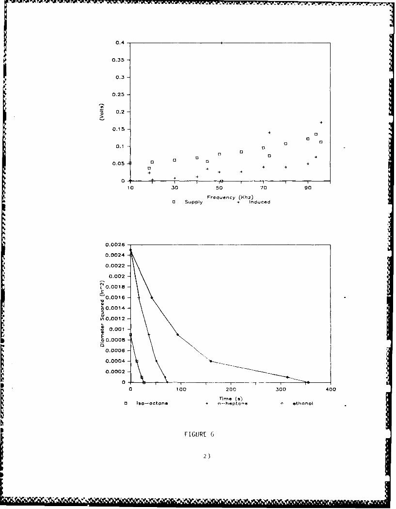
6 Results from Evaporation Tests on Ethanol, n-Heptane, andIso-Octane. Dashed line indicates theoretical slope for
12 cm/s flow .................................................. 23
7 Schematic Diagram of Setup to Study Excimer Laser InducedIgnition of Droplets Due to Air Plasma Spark Formation ....... 26 S.
5
IF 11 ,11
111111, 1 1

Piezoelectrically driven ultrasonic resonators were found to
be simple in design, construction, and testing. Over a dozen
resonator configurations were made and tested for their operating
characteristics. Two proved to be especially reliable at
levitating droplets and were subsequently employed in vaporiza-
tion and ignition studies on liquid fuels such as ethanol,
n-heptane, iso-octane, and decane. These tests were performed at
resonant frequencies of approximately 20 kHz and 50 kHz, the
former value being a fundamental resonator frequency and thelatter value being a first harmonic. Droplet stability in
suspension was not as good as desired for accurate determinationsof droplet diameters. However, the stability was more than
adequate to test various ignition techniques which included use
of a) hot wires, b) spark discharges, c) open flames, d) excimer S
laser produced air breakdown, and e) CO2 laser heating. All
attempts proved unsuccessful. The reason for this is not known
at this time but the effect of the acoustic pressure field on
ignition is a key area of concern. Vaporization tests conductedon the droplets demonstrated that the suspending force in the
acoustic field is equivalent to approximately a 12 cm/s flow
across the droplet. The magnitude of this velocity, although
small, could have detrimental effects on the droplet ignition
mechanisms.
.
7

1 INTRODUCTION
Much combustion research consists of characterizing theproperties of sprays. Due to their complexity, many fundamentalaspects important in characterizing spray combustion are obscure.
One example of this involves the study of liquid fuel and liquid
propellant droplet combustion. Progress in this area has been
accomplished not by studies involving spray combustion, but by
investigating the burning of isolated single droplets under
various conditions. Many techniques have been developed for such
studies involving either freely falling droplets or fiber
suspended ones. One technique not previously employed in
combustion work is droplet levitation. The work reported on here
involves an investigation of the acoustic levitation technique
and its possible use in studies of liquid fuel and propellant
combustion.
Aerodynamic, acoustic, and electrostatic principles have
been exploited in the past to design levitation devices where a
single droplet could be suspended almost free of motion. 1- 3 For
our purpose of suspending a liquid fuel or propellant droplet,
aerodynamic and electrostatic techniques have been eliminated for
the following reasons. With aerodynamic techniques, it is
extremely difficult to maintain a gas flow of sufficient
stability to keep small droplets stationary. Furthermore,
adapting this technique to a high pressure environment adds much
more complexity to the system. Electrostatic devices would be
expensive, bulky, and not easily adaptable to the high pressureenvironment necessary to conduct liquid propellant studies. In
addition, it is doubtful whether a burning droplet will retainits charge and hence position in the electrostatic field. An
acoustic levitation device, on the other hand, has several
attractive features; it is relatively inexpensive, it can be madecompact and easily incorporated into high pressure vessels, and
it has the capability of suspending small droplets motionless.
9

The approach taken here is the development of a basic
piezoelectric driven resonator designed for useful power output
in the frequency range between 20 and 60 kHz. Design
constraints include compact construction while maintaining asufficiently strong acoustic pressure field to levitate droplets.
For this purpose, a stable frequency source and power amplifier
are required to drive the piezoelectric elements of the
resonator. The device is used to suspend droplets of various
fuels while tests are performed on the levitated specimen. These
tests include evaporation measurements and ignition studies. The
objectives of this investigation are:
a) Survey the literature for the various designs of
piezoelectrically driven ultrasonic resonators.
b) Construct a compact levitator which is driven by
piezoelectric ceramic elements. Overall dimensions not
to exceed 2.5 inches in diameter and 7.5 inches in
length.
c) Acoustically suspend liquid drops in the diameter range
of 0.3 to 1.0 millimeters.
d) Find optimum operating parameters of the acoustic
levitator for making drops motionless.
e) Find a minimal perturbation igniter technique for
ignition of acoustically suspended combustible liquid
drops.
f) Ignite an acoustically levitated combustible droplet
and monitor the stability as combustion takes place.
g) Render an evaluation on the practicality of using
acoustic levitation to study combustion phenomena of
individual liquid drops.
10

This report describes the work accomplished toward
fulfilling these objectives during the contract period of 22 May
to 30 September 1987. During the course of this work, various
resonator designs and clamping techniques were considered and
several resonators were built and tested. An evaluation of the
most reliable design has been provided in this work.
2 REVIEW
Ultrasonic resonators have been employed for a variety of
applications.4 -6 For example, one design based on a piezoelec-
tric driven resonator was used for atomization of fuel oil.4 Thevibration of the resonator end caused a liquid sheet of fuel
covering it to break off in the form of droplets with an average
diameter of 25 micrometers. A vibrational frequency of 60 kHz
was used in this study. Atomized fuel collected at the planes of
sound pressure minima when a reflector was used to set up a
standing wave pattern in air. Fuel delivery to the end of the
resonator was accomplished through a center tube so that liquid
could be supplied to the resonator at a vibrational nodal point.
Tests on the device demonstrated little wear or fatigue
developing after 4 x 10¹² cycles at a maximum resonator end
stress of 11,000 psi. No clogging was observed with the fuel oil
used in the study.
This investigation was note worthy because of the various
resonator clamping designs studied. It was shown that clamping
techniques were of great importance for obtaining proper acoustic
coupling between the piezoelectric drivers and the resonator bulk
material. Horn designs were also studied to increase the
resonator end displacement amplitude. A stepped horn design
proved useful for increasing the acoustic intensity by a factor
of 6 to 10 times.
In another study, a high power piezoelectric transducer was
designed and tested that generated 10 kW of power at an
efficiency of 97.5%.5 The resonator included a catanary horn
11

design specially developed for the high power application.
Testing of the system involved attaching two similar devices
together as a motor-generator combination and recording input and
output power. At lower power levels, it was recommended that astepped horn be used to obtain high amplification factors.
However, the stepped horn resulted in lower overall efficiency.
The catanary type proved most efficient. The entire assembly
weighed 22 lbs. and produced a 0.004 inch peak-to-peak
vibrational amplitude at the end of the horn. Mild steel was
used in the construction of the resonator.
An in depth study of the stability of acoustically suspended
liquid droplets demonstrated that droplets move towards planes ofminimum sound pressure at resonance.6 In a resonator/reflector
configuration, the first two sound pressure minima where shown to
be the best. In the untuned state where the reflector distance
was not set to the optimal spacing, the pressure maxima were well
below the tuned pressure minima. Using a hot wire to map out thevelocity in the acoustic field, the peak velocity positions were
identified. Further experiments showed that a radial distribu-
tion of sound pressure existed and provided a means ofstabilizing droplets in the radial direction. This was
demonstrated by showing stable levitation with the resonator
rotated through 90 degrees.
Other studies using a spherical resonator geometry have been
conducted.7 The stability of droplets was reported to be
influenced by the ratio of viscous drag to radiation pressure.When this ratio was between 0.25 and 0.75, the onset of
instability occurred. Experiments demonstrated that dropletsbelow 0.5 mm in diameter were ejected for the pressure well, thus
falling out of the acoustic field produced by the resonator and
reflector.
Center bolt resonators have been designed and constructedfor studies in space borne laboratories as well as in groundbased facilities.8 Designs incorporating stepped horns connected
12

to circular vibrating plates for coupling the ultrasonic
vibrations to the environment have shown reliable operation for
positioning specimens in laboratory furnaces and high pressure
vessels. Applications of the levitation equipment included
studies of surface waves on freely suspended liquids, variations
of the surface tension with temperature, and optical diffraction
properties of transparent substances. The criteria for efficient
coupling between the resonator and the acoustic medium is given
where it was shown that the resonator end diameter should be
larger than the wavelength of the sound frequency.
3 RESONATOR DESIGN
The resonator design employed in this work uses the
principle of the piezoelectric effect. A ceramic disk having
this property expands and contracts as an AC voltage differential
is applied across it. In a typical design, two disks are
sandwiched between two metal cylinders. The disks expand and
contract in opposite directions simultaneously. When an AC
signal is applied to the device whose frequency is f, a resonant
wave is set up in the metal cylinders if the overall resonator
length is )/2 where X = c/f. Here c is the speed of sound in the
metal and x is the wavelength. The result of the resonant
condition is high amplitude displacement of the two ends of the
device -ausing sound energy to be transmitted into the
surrounding environment. If a flat reflector is place an
integral number of wavelengths (now in air) from the end of the
resonator, an acoustic standing wave pattern can be set.
A
The basic resonator design employed in this study is shown
in Fig. 1. Two piezoelectric ceramic disks, with the same
polarity faces together, are sandwiched between two matched
aluminum cylinders. A center hole exists in each of the disks so
that a bolt can be used to clamp the assembly together. A
conductive plate is placed between the two disks to provide an
electrode for driving the piezoelectric elements. The
13

LUJ
zLUI
_ CD
C) 0
CJ <J 0-J
ry0 LUJo N HF-LU LU __Z
LUJ< C)
z =
LU
0 LU___ L
LUJ_ Cy-
WL LUJUCC> ry z
*LLJ
-J
0 0DN z
m LUJx :D
14
S.1*------------------------ '- **,~-'S-*.,* i*.. '.F ~ S

non-threaded section of the bolt is sheathed in insulating
plastic to prevent the center electrode from shorting out to
ground (the cylinders are held at ground potential).
The goal was to produce a resonator that supported fuel
droplets at a resonant frequency between 20 and 60 kHz. The
resonator developed to achieve this goal had a diameter of 1.06
inches. The aluminum (6061-T6) cylinders on each side of the
0.080 inch thick ceramic drivers were 1.825 inches long. A plate
0.060 inches thick was the center electrode for the design. A
center bolt had a length of 1.50 inches, a diameter of 3/8 of an
inch and was made out of 304 stainless steel. The threads on the
bolt were 3/8 inch NC. A resonant fundamental frequency of p
slightly below 20 kHz was measured and a first and second
harmonic near 50 kHz and between 90 and 100 kHz, respectively,
were found. Figure 2 shows the experimentally determined
resonant frequencies. A second device having the same length as
above and a diameter of 1.465 inches was also constructed and
proved to be resonant at approximately the same frequencies
(fundamental at 22 kHz). Clamping pressure on the piezoelectric
disks had a significant effect on the resonator efficiency, and
hence sound intensity level. Figure 3 shows the relationship
between the pressure applied to the ceramic disks and the
relative increase in detected sound level. The top graph is for
ceramic disks 0.080 inches thick while the bottom is for disks
0.125 inches thick. As indicated by the graph, the sound level
increased to a point at all three resonant frequencies tested
when the clamping pressure increased.
Two different types of resonators were tested. The center
bolt type described above was used in all experiments reported on
here. Another design, employing flange clamping, was also built
and tested. The flange resonator was never successful at
supporting droplets and since the center bolt resonator was
simple and effective, it was exclusively used in all levitation
experiments. Horns were also studied with various designs being

1.7-1.6
1.5-1.4-
1.3
1.2
1.1
75 0.9> 0.8
0.70.6
0.5
0.4
0.3-
0.2
0-
10 30 50 70 90 110
Frequency (kHz)a first data 4 after tightening
FIGURE 2
16

WO 11P OO-M !,
900-
800-
700
S 600-
' 500-
.2 400
0 300-4:
200-
100
20 24 28 32 36 40 44
Torque (ft-Ibs)0 22 Khz + 55 Khz o 90 Khz
320
300
280
260
5' 240-E 220
, 200
u 180
2 160
S 140
.U 120-
100
80
60
40
20
25 27 29 31 33 35 37 39 41 43 45
a 25 Khz + 65~eftIs Kh 115 Khz
FIGURE 3
17

constructed. None appeared to be useful for amplifying the
acoustic sound pressure levels, and so they were not pursued
further in this study.
The experimental apparatus used to conduct the frequency,
sound level, and levitation measurements is shown in Fig. 4. A
sine wave generator produced the required signal which was first
routed to a counter/timer to obtain an accurate reading of the
output frequency, and then to a 10 Watt amplifier for boosting
the voltage and power levels of the signal supplied to the
resonator. An oscilloscope was used to monitor both the voltagesupplied to the resonator and the acoustic signal detected by
another ceramic disk which doubled as an effective flat plate
reflector. The resonator was mounted in a translator that
provided accurate adjustment of the distance between the
resonator and the reflector.
4 RESULTS
Droplets were supported at both 20 and 60 kHz with the 1.06
inch liameter resonator. The 1.465 inch diameter resonator only
supported drops at a resonant frequency of 22 kHz but proved
useful in stability tests and was employed in all evaporation
tests with liquid fuels. This resonator closely approach the
condition of rendering motionless the suspended droplets hence
diameter measurements for evaporation tests were easier to
perform with this device. Typical driving signals were between
25 and 75 volts peak-to-peak.
Size, stability, and how the droplets were placed on the
sound planes were important considerations in this study.
Theoretically, the largest droplet diameter that could be
levitated in air at 60 kHz, based on the consideration that a
droplet cannot cross two sound pressure minima, is 0.4 cm.
Experimentally, the largest droplet suspended was ellipsoidal in
shape having a mean diameter of 0.2 cm, roughly one half the
theoretical limit. Attempts to suspend larger droplets produced
18

000COUNTER/ 0MM FUNCTION
TIMER GENERATOR
INOU
IN10 WATT AMP OU
RESONATOR
0000
OSCILLOSCOPE_____
0 0 0 00 0 0 0 ACOUSTIC00 0 0 PICK-UP00 0
FIGURE 4
19

a disk shaped specimen as seen in Fig. 5 (top). This disk waso.1 cm thick and 0.5 cm in diameter. As these disks evaporated,they became spherical and smaller. The smaller spherical
droplets tended to oscillate about a fixed point in the acoustic
field. The amplitude of oscillation was approximately 0.005
inches. Different fuels oscillated at different rates. For
example, methanol vibrated so rapidly that no accurate diameter
measurements could be obtained. A droplet was deposited within
the acoustic field with a hypodermic syringe and needle. It was
important to have a very small tip in order to minimized the
surface tension effects keeping the droplet attached to the
needle. In some cases, a metal needle was used. In other cases,
it proved useful to outfit the syringe with a glass tube that had
been drawn down to a fine capillary (100 micrometers in
diameter). It was observed that high sound intensity levels
permitted easy droplet depositing within the resonant field.
5 VAPORIZATION TESTS
The vaporization tests were performed with the apparatus
described above. To observe the size of droplets as a function
of time, a binocular microscope was employed having a reticle
with a resolution of 0.001 inches. Data from a series of
measurements on various liquid fuels can be found in Appendix A.
Note that in these measurements the drops oscillated about their
equilibrium positions, thus rendering measurements of their
diameters difficult. Five runs were averaged together to
minimize the errors associated with these measurements.
Theoretical considerations of droplet evaporation in a
quiescent environment leads to a linear plot of the droplet
diameter squared as a function of time. The linear plot is
characterized by a slope of -x calculated by,9
' 4Nup.a 9 1)Pi
20

?WU JZ~Ji mW5 aiXK w 6 r-w m'.VVV N777., 7T,x-v.Y' ~ l Nv- Yrnjr K'Kr PV.r w7 h r 'r W ~WVVyrL"
FIGURE 5
21

I,. W WM W7
*B is a nondimensional constant relating diffusion and convection.
The Nusselt number is represented by Nu and the density is P. a
is the thermal diffusivity. Subscripts g and 1 refer to the gas
and liquid phases, respectively. The thermal diffusivity and
density can be found in the CRC handbook. When there is no flow
by the droplet the Nusselt number is equal to two. For cases of
nonzero flow rate where the flow velocity is u, the droplet
diameter is d, the kinematic viscosity is v, and the thermal
diffusivity is a, the Nusselt number equals:
(ud (VONu =2+0.6 y .
Figure 6 (bottom) shows the results of evaporation tests on
ethanol, n-heptane, and iso-octane. The dashed line shows the
theoretical results when a flow of 12 cm/s is assumed to pass
across a droplet having an initial diameter of 0.03 inches.
These comparisons show that a flow is developed by the acoustic
field that supports the droplets.
6 DROPLET IGNITION STUDIES
Table I lists the techniques that were tried for igniting
fuel droplets in this study. The first, and simplest, method was
the use of a pre-ignited match. A series of attempts to ignite.a
levitated droplet resulted in a disruption of the acoustic field
causing the droplet to fall out of suspension. The second
technique used was a hot tungsten wire. Although repeated use of
a glowing tungsten filament ended with eventual failure of the
wire due to oxidation, the filament lasted long enough to observe
the same results as those occurring with the lighted match.
The next technique employed a spark generator to pass a
discharge through the suspended droplet. A spark gap 0.5 cm wide
was created with two electrodes having diameters of approximately
0.05 cm. The electrodes were moved into a position where the gap
22
0.5
0.35
0.25
0.2
0.15-+
0
0.1 -0
0 4+
4 4 4
0- + 4
10 30 so 70 90
Frequency (Khz)0 Supply + Induced
0.0026-
0.0024-
0.0022
0.002
('4(0.0018C-0.0016
S0.00 14
L0.0012
.90.0008
0.0006
0.0004
0.0002
0100 200 300 400
FIGURE 6I 23
nv. o. . ..-. .

TABLE I
Ignition Techniques Studied
Technique Fuel Results
open Flame n-Hexane Loss of Suspension
iso-Octane Loss of Suspension
(all ignited on fiber)
Hot Wire n-Hexane Loss of Suspension(Chromel wire) Ethanol Loss of Suspension
Methanol Loss of Suspension
Hot Wire n-Hexane Ignition on Fiber Only(Tungsten) Methanol Ignition on Fiber Only
Spark Discharge Decane No Ignition
n-Hexane Ignition on Fiber Only
Ethanol No Ignition
Methanol No Ignition
Excimer Laser Ethanol No Ignition
n-Hexane No Ignition
CO2 Laser Ethanol Loss of Suspension
n-Hexane Loss of Suspension
Decane Rapid Evaporation
241

contained the levitated droplet. A short duration, 25 kV spark
discharge was made to jump the gap. A large number of attempts
to ignite the droplets were made. Discharges appeared to pass
very close to, or even through the droplet with no apparent
effect other than to occasionally eject the droplet out of the
acoustic field. The reason for the failure of this technique isspeculative, but apparently the resonator sound energy inhibits
the ignition mechanisms associated with droplet combustion. This
problem does not occur with fiber suspended droplets which can be
ignited with a discharge.
A fourth technique employed an excimer laser (ArF) to induce
a breakdown of the air next to the droplet. The setup is shown
in Fig. 7. Sufficient energy was available to disintegrate the
droplet when it was in the beam path, or eject the droplet from
the acoustic field by shock wave disturbances. At lower energy
settings, a laser induced plasma could be observed at the beam
focus (a 10 cm focal length lens was used). Using both hexane
and ethanol droplets, the location of the plasma was moved to
positions above, below, and to the side of the droplet with no
apparent effect other than to set the droplet into oscillation.
The plasma was even caused to impinge slightly on the dropletwhich caused violent oscillations or ejected the droplet from the
field. No ignition was observed.
The last technique t "ed was ignition using a CO2 laser
emitting at 10.6 micrometers. The total available power for this
experiment was 50 watts, however, much reduced power levels were
necessary in order to conduct the experiment. Unfocussed
radiation from the laser was used to fully illuminate the droplet
from one side. From wavelength considerations, it was
anticipated that rapid heating would be available for the
experiment. Droplets attached to capillary tubes were firststudied. Rapid evaporation could be induced in the attached
droplets with some evidence of pyrolysis occurring from smoke
generated during the process. No ignition was observed in these
25
Loam IIII'MIII J1, ZNVII

0LJ I
x LaJ
LaJ
A]]J
LaJ
0~0
-J 0
LAJ
Of0 -
26S

4, ;V -~ - Y- _7 pr W a1.- - TUW
preliminary experiments. During droplet levitation, decane
remained stable during irradiation. Rapid evaporation was
observed with the CO 2 laser output at approximately 2 to 3 watts.
Again, some evidence of pyrolysis was observed in the form of
smoke. Other liquids such as hexane and ethanol became unstable
upon irradiation and fell out of suspension. No ignition was
observed during these experiments. Focussing the laser beam was
not attempted, neither was use made of CO2 laser breakdown as a
potential ignition source. It was believed that such attempts
would not be productive because of the violent nature
accompanying plasma formation at a wavelength of 10.6
micrometers.
The final results of the ignition experiments were negative.
Although many techniques were explored for their usefulness, no
minimum perturbation ignition method was found in this study.
7 CONCLUSION
Piezoelectrically driven ultrasonic resonators were found to
be simple in design, construction, and testing. Over a dozen
resonator configurations were made and tested for their operating
characteristics. Two proved to be especially reliable at
levitating droplets and were subsequently employed in vaporiza-
tion and ignition studies on liquid fuels such as ethanol,
n-heptane, iso-octane, and decane. These tests were performed -at
resonant frequencies of approximately 20 kHz and 50 kHz, the
former value being a fundamental resonator frequency and the
latter value being a first harmonic. Droplet stability in
suspension was not as good as desired for accurate determinations
of droplet diameters. However, the stability was more than
adequate to test various ignition techniques which included use
of a) hot wires, b) spark discharges, c) open flames, d) excimer
laser produced air breakdown, and e) CO 2 laser heating. All
attempts proved unsuccessful. The reason for this is not known
at this time but the effect of the acoustic pressure field on
ignition is a key area of concern. Vaporization tests conducted
27

on the droplets demonstrated that the suspending force in the
acoustic field is equivalent to approximately a 12 cm/s flow
across the droplet. The magnitude of this velocity, although
small, could have detrimental effects on the droplet ignition
mechanisms.
r
2.8. p
*4
'ab
.S
28

REFERENCES .
1) W.A. Oran and L.H. Berge, Rev. Sci. Instrum..- 53, 851
(1982).
2) A.R. Hanson, E.G. Domich, H.S. Adams, Rev. Sci.Instrum..
35, 1031 (1964).
3) E.J. Davis, Aerosol Science and Technology, 2, 121 (1983).
4) R.R. Perron, IEEE Trans. Sonics and Ultrasonics. SU-14,
149 (1967).
5) H. Minchenko, IEEE Trans. Sonics and Ultrasonics. SU-16,
126 (1969).
6) R.R. Wymark, Ultrasonics. 13, 251 (1975).
7) M.C. Lee and I. Feng, Rev. Sci. Instrum.. 53, 854 (1982).
8) E.H. Trinh, Rev. Sci. Instrum.. 56, 2059 (1985).
9) A.M. Kanury, "Combustion Phenomena," (Gordon and Breach -
Science Publishers, New York, 1975), p. 166.
29 '

313
bumumt

~~~4. ~ ~ r -,."**~~~Y W W PL "KYW www W.W -
VAPORIZATION DJATA
1 112"~ RESONATOR tightened to 80 Ft-lb3S volts driving at 20.7 kHz160 mV acoustic pickup76.6 F
n-heptane
TIN'E (s) DIA (in) TIM1E [s] DIA (in)
0 0.05 -20 0.07is 0.04* -S 0.0635 0.03 0 0.0555 0.015 10 0.01f
67 0.01 4~0 0.02S70 0.000 s0 0.!02
65 0.0170 0.000
TIM1E (s) DIA (in) TIME (s) DIA (in)
-4±0 0.08 -30 0.06-23 0.07 -20 0.07
-1f0.06 -10 0.06o 0.05 0 0.05
10 0.0'*f 31 0.04i21 0.035 '*9 0.03
4*7 0.02 69 0.0260 0.015 80 0.0167 0.01 88 0.000
AVJERAGE VALUEST1.11 Cs) DIA [in) TIME (s) DIA (in)
-15 0.06 0 0.05O 0.05 1E.8 00
18 0 .04* 36.4- 0.0336 0.03 51.3 0.02
450.02 68.8 0.01E5 0.01 73.3 0.00067 0.000
33

ethanol
TIME (s] DIA (in) TIME Cs] DIA (in)
-'*0 0.06 0 0.030 0.05 *5 00'* 0 0. 04 130 0.02586 0.03 209 0.02152 0.02 318 0.01350 0.01 345S 0.000'-06 0.000
AVERAGE VA~LUESTINE Es] DIA (in)
0 0.05'*2.S 0.0L*
94. 00.03180.5 0.02334-. 0 0.0137S.5 0.000
34

so-octane
TIlE Is) DIA (in] TIlE Cs) DIA (in)
-8 0.0 0 0.03
0 0.03 11 0.02is 0.02 19 0.01521 0.01 24 0.0127 0.000
TIME Cs] DIA (in] TIME Is] DIA (in)
-9 0.04 0 0.03
0 0.03 1t 0.02
10 0.02 24 0.01
16 0.015 28 0.00020 0.0123 0.000
AVERAGE VALUESTIME Cs] DIA (in3
0 0.0312.5 0.0222.3 0.0126.6 0.000
methanol
TIME Cs] DIA (in)
0 0.O04245 0.000
To unstable to make any further measurements
351

DISTRIBUTION LIST
No. Of No. Of
Copies Organization Copies Organization
12 Administrator I Director
Defense Technical Info Center US Army Aviation Research
ATTN: DTIC-FDAC and Technology Activity
Cameron Station, Bldg. 5 Ames Research Center
Alexandria, VA 22304-6145 Moffett Field, CA 94035-1099
HO DA 4 Commander
DAMA-ART-M US Army Research Office %
Washington, DC 20310 ATTN: R. Ghirardelli
D. Mann
Commander R. Singleton
US Army Materiel Command R. Shaw
ATTN: AMCDRA-ST P.O. Box 12211
5001 Eisenhower Avenue Research Triangle Park, NC
Alexandria, VA 22333-0001 27709-2211
10 C.I.A. 1 Commander
OIR/DB/Standard US Army Communications -
GE47 HO Electronics Command
Washington, DC 20505 ATTN: AMSEL-EDFort Monmouth, NJ 07703
CommanderUS Army ARDEC 1 Commander
ATTN: SMCAR-MSI CECOM R&D Technical Library
Dover, NJ 07801-5001 ATTN: AMSEL-IM-L,Reports Section B.2700
Commander Fort Monmouth, NJ 07703-5000
US Army ARDEC
ATTN: SMCAR-TDC 2 Commander
Dover, NJ 07801 Armament R&D CenterUS Army AMCCOM
Commander ATTN: SMCAR-LCA-G,
US AMCCOM ARDEC CCAC D.S. Downs
Benet Weapons Laboratory J.A. Lannon
ATTN: SMCAR-CCB-TL Dover, NJ 07801
Watervliet, NY 12189-4050
1 Commander
US Army Armament, Munitions Armament R&D Center
and Chemical Command US Army AMCCOM
ATTN: AMSMC-IMP-L ATTN: SMCAR-LC-G,
Rock Island, IL 61299-7300 L. HarrisDover, NJ 07801
Commander
US Army Aviation Systems 1 Commander
Command Armament R&D Center
ATTN: AMSAV-ES US Army AMCCOM
4300 Goodfellow Blvd. ATTN: SMCAR-SCA-T,
St. Louis, MO 63120-1798 L. Stiefel
Dover, NJ 07801
37
OUR 1011011001 MMMW

DISTRIBUTION LIST
No. Of No. OfCopies Organization Copies Organization
Commander 1 Office of Naval ResearchUS Army Missile Command Department of the NavyResearch, Development and ATTN: R.S. Miller, Code 432Engineering Center 800 N. Quincy Street
ATTN: AMSMI-RD Arlington, VA 22217Redstone Arsenal, AL 35898
I CommanderCommander Naval Air Systems CommandUS Army Missile and Space ATTN: J. Ramnarace,
Intelligence Center AIR-54111CATTN: AMSMI-YDL Washington, DC 20360Redstone Arsenal, AL 35898-5000
2 Commander2 Commander Naval Ordnance Station
US Army Missile Command ATTN: C. IrishATTN: AMSMI-RK, D.J. Ifshin P.L. Stang, Code 515
W. Wharton Indian Head, MD 20640Redstone Arsenal, AL 35898
1 CommanderCommander Naval Surface Weapons CenterUS Army Missile Command ATTN: J.L. East, Jr., G-23ATTN: AMSMI-RKA, A.R. Maykut Dahlgren, VA 22448-5000Redstone Arsenal, AL 35898-5249
2 CommanderCommander Naval Surface Weapons CenterUS Army Tank Automotive ATTN: R. Bernecker, R-13
Command G.B. Wilmot, R-16ATTN: AMSTA-TSL Silver Spring, MD 20902-5000Warren, MI 48397-5000
1 CommanderDirector Naval Weapons CenterUS Army TRADOC Systems ATTN: R.L. Derr, Code 389
Analysis Center China Lake, CA 93555ATTN: ATOR-TSLWhite Sands Missile Range, 2 CommanderNM 88002-5502 Naval Weapons Center
ATTN: Code 3891, T. BoggsCommandant K.J. GrahamUS Army Infantry School China Lake, CA 93555ATTN: ATSH-CD-CS-ORFort Benning, GA 31905-5400 5 Commander
Naval Research LaboratoryCommander ATTN: M.C. LinLIS Army Development and J. McDonald
Employment Agency E. OranATTN: MODE-ORO J. ShnurFort Lewis, WA 98433-5000 R.J. Doyle, Code 6110
Washington, DC 20375
38
' W¢' '' ' " '? ' *rl l " ' "IV " I

DISTRIBUTION LIST
No. Of No. OfCopies Organization Copies Organization
1 Commanding Officer 1 OSD/SDIO/USTNaval Underwater Systems ATTN: L.H. Caveny
Center Weapons Dept. PentagonATTN: R.S. Lazar/Code 36301 Washington, DC 20301-7100Newport, RI 02840
1 Aerojet Solid Propulsion Co.Superintendent ATTN: P. MicheliNaval Postgraduate School Sacramento, CA 95813 %
Dept. of AeronauticsATTN: D.W. Netzer I Applied CombustionMonterey, CA 93940 Technology, Inc.
ATTN: A.M. VarneyAFRPL/DY, Stop 24 P.O. Box 17885
ATTN: R. Corley Orlando, FL 32860R. GeislerJ. Levine 2 Applied Mechanics ReviewsD. Weaver The American Society of
Edwards AFB, CA 93523-5000 Mechanical EngineersATTN: R.E. White
AFRPL/MKPB, Stop 24 A.B. WenzelATTN: B. Goshgarian 345 E. 47th StreetEdwards AFB, CA 93523-5000 New York, NY 10017
AFOSR 1 Atlantic Research Corp.ATTN: J.M. Tishkoff ATTN: M.K. KingBoiling Air Force Base 5390 Cherokee AvenueWashington, DC 20332 Alexandria, VA 22314
AFATL/DOIL (Tech Info Center) 1 Atlantic Research Corp.Eglin AFB, FL 32542-5438 ATTN: R.H.W. Waesche
7511 Wellington RoadAir Force Weapons Laboratory Gainesville, VA 22065AFWL/SUL
ATTN: V. King I AVCO Everett Rsch. Lab. Div.Kirtland AFB, NM 87117 ATTN: D. Stickler
2385 Revere Beach ParkwayNASA Everett, MA 02149Langley Research Center
Langley Station I Battelle Memorial InstituteATTN: G.B. Northam/MS 168 Tactical Technology CenterHampton, VA 23365 ATTN: J. Huggins
505 King Avenue4 National Bureau of Standards Columbus, OH 43201
ATTN: J. HastieM. Jacox 1 Cohen Professional ServicesT. Kashiwagi ATTN: N.S. CohenH. Semerjian 141 Channing Street
US Department of Commerce Redlands, CA 92373Washington, DC 20234
39

DISTRIBUTION LIST
No. Of No. Of
Coies Organization Copies Organization
Exxon Research & Eng. Co. I Hercules, Inc.
Government Research Lab Bacchus Works
ATTN: A. Dean ATTN: K.P. McCarty
P.O. Box 48 P.O. Box 98
Linden, NJ 07036 Magna, UT 84044
Ford Aerospace and 1 Honeywell, Inc.
Communications Corp. Government and Aerospace
DIVAD Division Products
Div. Hq., Irvine ATTN: D.E. Broden/
ATTN: D. Williams MS MN50-2000
Main Street & Ford Road 600 2nd Street NE
Newport Beach, CA 92663 Hopkins, MN 55343
General Applied Science I IBM Corporation
Laboratories, Inc. ATTN: A.C. Tam
ATTN: J.I. Erdos Research Division
425 Merrick Avenue 5600 Cottle Road
Westbury, NY 11590 San Jose, CA 95193
General Electric Armament I lIT Research Institute
& Electrical Systems ATTN: R.F. Remaly
ATTN: M.J. Bulman 10 West 35th Street
Lakeside Avenue Chicago, IL 60616
Burlington, VT 05401
2 Director
General Electric Company Lawrence Livermore
2352 Jade Lane National Laboratory
Schenectady, NY 12309 ATTN: C. WestbrookM. Costantino
General Electric Ordnance P.O. Box 808
Systems Livermore, CA 94550
ATTN: J. Mandzy
100 Plastics Avenue I Lockheed Missiles & Spc'p Co.
Pittsfield, MA 01203 ATTN: George Lo
3251 Hanover Street
2 General Motors Rsch Labs Dept. 52-35/B204/2
Physics Department Palo Alto, CA 94304
ATTN: T. Sloan
R. Teets 1 Los Alamos National Lab
Warren, MI 48090 ATTN: B. NicholsT7, MS-B284
2 Hercules, Inc. P.O. Box 1663
Allegany Ballistics Lab. Los Alamos, NM 87545
ATTN: R.R. Miller
E.A. Yount 1 National Science Foundation
P.O. Box 210 ATTN: A.B. Harvey
Cumberland, MD 21501 Washington, DC 20550
40

DISTRIBUTION LIST
No. Of No. Of
Copies Organization Copies Organization
Olin Corporation 3 SRI InternationalSmokeless Powder Operations ATTN: G. SmithATTN: V. McDonald D. CrosleyP.O. Box 222 D. Golden
St. Marks, FL 32355 333 Ravenswood AvenueMenlo Park, CA 94025
1 Paul Gough Associates, Inc.ATTN: P.S. Gough 1 Stevens Institute of Tech.1048 South Street Davidson Laboratory
Portsmouth, NH 03801 ATTN: R. McAlevy, IIIHoboken, NJ 07030
2 Princeton CombustionResearch Laboratories, Inc. 1 Textron, Inc.
ATTN: M. Summerfield Bell Aerospace Co. DivisionN.A. Messina ATTN: T.M. Ferger
475 US Highway One P.O. Box 1Monmouth Junction, NJ 08852 Buffalo, NY 14240
Hughes Aircraft Company 1 Thiokol CorporationATTN: T.E. Ward Elkton Division
8433 Fallbrook Avenue ATTN: W.N. BrundigeCanoga Park, CA 91303 P.O. Box 241
Elkton, MD 21921
Rockwell International Corp.Rocketdyne Division 1 Thiokol Corporation
ATTN: J.E. Flanagan/HB02 Huntsville Division6633 Canoga Avenue ATTN: R. GlickCanoga Park, CA 91304 Huntsville, AL 35807
4 Sandia National Laboratories 3 Thiokol CorporationCombustion Sciences Dept. Wasatch DivisionATTN: R. Cattolica ATTN: S.J. Bennett
S. Johnston P.O. Box 524P. Mattern Brigham City, UT 84302
D. StephensonLivermore, CA 94550 1 TRW
ATTN: M.S. ChouScience Applications, Inc. MSRI-1016ATTN: R.B. Edelman 1 Parke23146 Cumorah Crest Redondo Beach, CA 90278Woodland Hills, CA 91364
1 United TechnologiesScience Applications, Inc. ATTN: A.C. EckbrethATTN: H.S. Pergament East Hartford, CT 06108
1100 State Road, Bldg. N
Princeton, NJ 08540
41

DISTRIBUTION LIST
No. Of No. OfCopies Organization Copies Organization
3 United Technologies Corp. 1 University of CaliforniaChemical Systems Division Los Alamos Scientific Lab.ATTN: R.S. Brown P.O. Box 1663, Mail Stop B216
T.D. Myers (2 copies) Los Alamos, NM 87545P.O. Box 50015
San Jose, CA 95150-0015 2 University of California,
Santa Barbara2 United Technologies Corp. Quantum Institute
ATTN: R.S. Brown ATTN: K. SchofieldR.O. McLaren M. Steinberg
P.O. Box 358 Santa Barbara, CA 93106Sunnyvale, CA 94086
2 University of Southern
Universal Propulsion Company CaliforniaATTN: H.J. McSpadden Dept. of ChemistryBlack Canyon Stage I ATTN: S. BensonBox 1140 C. WittigPhoenix, AZ 85029 Los Angeles, CA 90007
Veritay Technology, Inc. 1 Case Western Reserve Univ.ATTN: E.B. Fisher Div. of Aerospace Sciences4845 Millersport Highway ATTN: J. TienP.O. Box 305 Cleveland, OH 44135
East Amherst, NY 14051-03051 Cornell University
Brigham Young University Department of ChemistryDept. of Chemical Engineering ATTN: T.A. CoolATTN: M.W. Beckstead Baker LaboratoryProvo, UT 84601 Ithaca, NY 14853
California Institute of Tech. 1 Univ. of Dayton Rsch Inst.Jet Propulsion Laboratory ATTN: D. CampbellATTN: MS 125/159 AFRPL/PAP Stop 244800 Oak Grove Drive Edwards AFB, CA 93523
Pasadena, CA 91103
1 University of FloridaCalifornia Institute of Dept. of ChemistryTechnology ATTN: J. Winefordner
ATTN: F.E.C. Culick/ Gainesville, FL 32611MC 301-46
204 Karman Lab. 3 Georgia Institute ofPasadena, CA 91125 Technology
School of AerospaceUniversity of California, Engineering
Berkeley ATTN: E. PriceMechanical Engineering Dept. W.C. StrahleATTN: J. Daily B.T. ZinnBerkeley, CA 94720 Atlanta, GA 30332
42

DISTRIBUTION LIST
No. Of No. Of
Copies Organization Copies Organization
University of Illinois 1 Purdue UniversityDept. of Mech. Eng. School of Aeronautics
ATTN: H. Krier and Astronautics
144MEB, 1206 W. Green St. ATTN: J.R. Osborn
Urbana, IL 61801 Grissom HallWest Lafayette, IN 47906
Johns Hopkins University/APLChemical Propulsion 1 Purdue University
Information Agency Department of ChemistryATTN: T.W. Christian ATTN: E. Grant
Johns Hopkins Road West Lafayette, IN 47906
Laurel, MD 20707
2 Purdue UniversityUniversity of Michigan School of MechanicalGas Dynamics Lab Engineering
Aerospace Engineering Bldg. ATTN: N.M. LaurendeauATTN: G.M. Faeth S.N.B. Murthy
Ann Arbor, MI 48109-2140 TSPC Chaffee Hall
West Lafayette, IN 47906University of MinnesotaDept. of Mechanical 1 Rensselaer Polytechnic Inst.
Engineering Dept. of Chemical EngineeringATTN: E. Fletcher ATTN: A. FontijnMinneapolis, MN 55455 Troy, NY 12181
3 Pennsylvania State University 1 Stanford University
Applied Research Laboratory Dept. of MechanicalATTN: K.K. Kuo Engineering
H. Palmer ATTN: R. Hanson
M. Micci Stanford, CA 94305
University Park, PA 16802
1 University of Texas
Polytechnic Institute of NY Dept. of ChemistryGraduate Center ATTN: W. Gardiner
ATTN: S. Lederman Austin, TX 78712Route 110
Farmingdale, NY 11735 1 University of Utah .e
Dept. of Chemical Engineering
2 Princeton University ATTN: G. FlandroForrestal Campus Library Salt Lake City, UT 84112
ATTN: K. Brezinsky
I. Glassman 1 Virginia Polytechnic
P.O. Box 710 Institute andPrinceton, NJ 08540 State University
ATTN: J.A. SchetzPrinceton University Blacksburg, VA 24061MAE Dept.
ATTN: F.A. Williams
Princeton, NJ 08544
43

DISTRIBUTION LIST
No. OfCopies Organization
CommandantUSAFAS
* ATTN: ATSF-TSM-CNFort Sill, OK 73503-5600
Aberdeen Proving Ground
Dir, USAMSAAATTN: AMXSY-D
AMXSY-MP, H. CohenCdr, USATECOM
ATTN: AMSTE-SI-FCdr, CRDC, AMCCOM
ATTN: SMCCR-RSP-ASMCCR-KUSMCCR-SPS- IL
'4
'
444

IL- . - 41 k- P67 -W 7 P71V- .- ; --
-. USER EVALUATION SHEET/CHANGE OF ADDRESS
This Laboratory undertakes a continuing effort to improve the quality of thereports it publishes. Your comments/answers to the items/questions below will
aid us in our efforts.
1. BRL Report Number Date of Report
2. Date Report Received
3. Does this report satisfy a need? (Comment on purpose, related project, or
other area of interest for which the report will be used.)
4. How specifically, is the report being used? (Information source, designdata, proceaure, source of ideas, etc.)
S. Has the information in this report led to any quantitative savings as faras man-hours or dollars saved, operating costs avoided or efficiencies achieved,
etc? If so, please elaborate.________________________
6. General Comments. What do you think should be changed to improve future
reports? (Indicate changes to organization, technical content, format, etc.)
Name
CURRENT Organization
ADDRESS Address
City, State, Zip
7. If indicating a Change of Address or Address Correction, please provide the
New or Correct Address in Block 6 above and the Old or Incorrect address below.
Name
OLD OrganizationADDRESS
Address
City, State, Zip
(Remove this sheet, fold as indicated, staple or tape closed, and mail.)
. C S -- a P

FOLD HERE
Director N OTG
US Army Ballistic Research Laboratory NECESSARYATTN: DRXBR-OD-ST IF MAILEDAberdeen Proving Ground, MD 21005-5066 IN THE
UNITED STATES
OFFICIAL BUSINESS _
PENALTY FOR PRIVATE USE. 3OO BUSINESS REPLY MAILFIRST CLASS PERMIT NO 12062 WASHINGTONDCPOSTAGE WILL BE PAID BY DEPARTMENT OF THE ARMY
DirectorUS Army Ballistic Research LaboratoryATTN: DRXBR-OD-STAberdeen Proving Ground, MD 21005-9989
-- - O FOLD HERE
.5

* * - - - - - 's'-'-
~ F
~Ap
I"
~%*
*%~* %~
S
1AIXFI.
~ S
'Iw w w w V V V V S 0