( 12 ) United States Patent ( 10 ) Patent No . : US 10 ...System that Adapts to Sloped Surfaces ....
24
US010105243B2 ( 12 ) United States Patent Hansen et al . ( 10 ) Patent No .: US 10 , 105 , 243 B2 (45) Date of Patent : * Oct . 23 , 2018 ( 54 ) ANKLE - FOOT PROSTHESIS FOR AUTOMATIC ADAPTATION TO SLOPED WALKING SURFACES ( 58 ) Field of Classification Search CPC . . . . . . . .. A61F 2 / 604 ; A61F 2/ 6607 ; A61F 2 / 66 ; A61F 2002 / 5003 ; A61F 2002 / 5006 ; ( Continued ) ( 71 ) Applicants : U . S . Department of Veterans Affairs , Washington , DC ( US ); Regents of the University of Minnesota , Minneapolis , MN ( US ) ( 56 ) References Cited U . S . PATENT DOCUMENTS ( 72 ) Inventors : Andrew H . Hansen , Apple Valley , MN ( US ); Eric A . Nickel , Brooklyn Park , MN ( US ) 2 , 843 , 853 A 4 , 923 , 475 A 7 / 1958 Mauch 5/ 1990 Gosthnian et al . ( Continued ) FOREIGN PATENT DOCUMENTS ( 73 ) Assignees : U .S . Department of Veterans Affairs , Washington , DC ( US ) ; Regents of the University of Minnesota , Minneapolis , MN ( US ) WO WO WO WO 2008 / 048658 A2 WO 2011 / 129892 A2 WO 2012 / 099709 A2 4 / 2008 10 / 2011 7 / 2012 ( * ) Notice : OTHER PUBLICATIONS Subject to any disclaimer , the term of this patent is extended or adjusted under 35 U . S . C . 154 (b ) by 0 days . This patent is subject to a terminal dis claimer . Hansen , A ., Childress , D ., Miff , S ., Gard , S . , Mesplay , K . ( 2004 ) The Human Ankle During Walking : Implications for Design of Biomimetic Ankle Prostheses and Orthoses . Journal of Biomechan ics , vol . 37 , No . 10 , 1467 - 1474 . ( Continued ) ( 21 ) Appl . No .: 15 / 359 , 242 ( 22 ) Filed : Nov . 22 , 2016 Primary Examiner — Thomas J Sweet Assistant Examiner — Christie Bahena ( 74 ) Attorney , Agent , or Firm — Ballard Spahr LLP ( 65 ) Prior Publication Data US 2017 / 0071761 A1 Mar . 16 , 2017 Related U .S . Application Data ( 63 ) Continuation of application No . 14 / 022 , 645 , filed on Sep . 10 , 2013 , now Pat . No . 9, 549 , 827 . ( Continued ) ( 57 ) ABSTRACT ( 51 ) Int . Cl . A61F 2 / 50 ( 2006 . 01 ) A61F 2 / 66 ( 2006 . 01 ) A61F 2 / 74 ( 2006 . 01 ) ( 52 ) U.S . Ci . CPC ... A61F 2 / 6607 ( 2013 . 01 ); A61F 2002 / 5006 ( 2013 . 01 ); A61F 2002 / 6642 ( 2013 . 01 ); A61F 2002 / 745 ( 2013 . 01 ) ; A61F 2002 / 748 ( 2013 . 01 ) An ankle - foot prosthesis includes a foot plate , an ankle frame attached to the foot plate , a yoke pivotally connected to the ankle frame and including a member for attaching to a leg , a damper having a first end connected to the yoke and a second end connected to the ankle frame , and a control mechanism for switching the damper between low and high settings . 20 Claims , 16 Drawing Sheets AFP 16 - - - 14 # 29 34
Transcript of ( 12 ) United States Patent ( 10 ) Patent No . : US 10 ...System that Adapts to Sloped Surfaces ....

US010105243B2
( 12 ) United States Patent Hansen et al .
( 10 ) Patent No . : US 10 , 105 , 243 B2 ( 45 ) Date of Patent : * Oct . 23 , 2018
( 54 ) ANKLE - FOOT PROSTHESIS FOR AUTOMATIC ADAPTATION TO SLOPED WALKING SURFACES
( 58 ) Field of Classification Search CPC . . . . . . . . . A61F 2 / 604 ; A61F 2 / 6607 ; A61F 2 / 66 ;
A61F 2002 / 5003 ; A61F 2002 / 5006 ; ( Continued ) ( 71 ) Applicants : U . S . Department of Veterans Affairs ,
Washington , DC ( US ) ; Regents of the University of Minnesota , Minneapolis , MN ( US ) ( 56 ) References Cited
U . S . PATENT DOCUMENTS ( 72 ) Inventors : Andrew H . Hansen , Apple Valley , MN
( US ) ; Eric A . Nickel , Brooklyn Park , MN ( US )
2 , 843 , 853 A 4 , 923 , 475 A
7 / 1958 Mauch 5 / 1990 Gosthnian et al .
( Continued ) FOREIGN PATENT DOCUMENTS
( 73 ) Assignees : U . S . Department of Veterans Affairs , Washington , DC ( US ) ; Regents of the University of Minnesota , Minneapolis , MN ( US ) WO
WO WO
WO 2008 / 048658 A2 WO 2011 / 129892 A2 WO 2012 / 099709 A2
4 / 2008 10 / 2011 7 / 2012
( * ) Notice : OTHER PUBLICATIONS
Subject to any disclaimer , the term of this patent is extended or adjusted under 35 U . S . C . 154 ( b ) by 0 days . This patent is subject to a terminal dis claimer .
Hansen , A . , Childress , D . , Miff , S . , Gard , S . , Mesplay , K . ( 2004 ) The Human Ankle During Walking : Implications for Design of Biomimetic Ankle Prostheses and Orthoses . Journal of Biomechan ics , vol . 37 , No . 10 , 1467 - 1474 .
( Continued ) ( 21 ) Appl . No . : 15 / 359 , 242
( 22 ) Filed : Nov . 22 , 2016 Primary Examiner — Thomas J Sweet Assistant Examiner — Christie Bahena ( 74 ) Attorney , Agent , or Firm — Ballard Spahr LLP
( 65 ) Prior Publication Data US 2017 / 0071761 A1 Mar . 16 , 2017
Related U . S . Application Data ( 63 ) Continuation of application No . 14 / 022 , 645 , filed on
Sep . 10 , 2013 , now Pat . No . 9 , 549 , 827 . ( Continued )
( 57 ) ABSTRACT
( 51 ) Int . Cl . A61F 2 / 50 ( 2006 . 01 ) A61F 2 / 66 ( 2006 . 01 ) A61F 2 / 74 ( 2006 . 01 )
( 52 ) U . S . Ci . CPC . . . A61F 2 / 6607 ( 2013 . 01 ) ; A61F 2002 / 5006
( 2013 . 01 ) ; A61F 2002 / 6642 ( 2013 . 01 ) ; A61F 2002 / 745 ( 2013 . 01 ) ; A61F 2002 / 748 ( 2013 . 01 )
An ankle - foot prosthesis includes a foot plate , an ankle frame attached to the foot plate , a yoke pivotally connected to the ankle frame and including a member for attaching to a leg , a damper having a first end connected to the yoke and a second end connected to the ankle frame , and a control mechanism for switching the damper between low and high settings .
20 Claims , 16 Drawing Sheets
AFP 16 - - - 14
# 29
34

US 10 , 105 , 243 B2 Page 2
Related U . S . Application Data ( 60 ) Provisional application No . 61 / 703 , 799 , filed on Sep .
21 , 2012 , provisional application No . 61 / 851 , 740 , filed on Mar . 13 , 2013 .
( 58 ) Field of Classification Search CPC . . . . . . A61F 2002 / 5007 ; A61F 2002 / 5033 ; A61F
2002 / 5035 ; A61F 2002 / 5073 ; A61F 2002 / 604 ; A61F 2002 / 6692 ; A61F 2002 / 6685 ; A61F 2002 / 6678 ; A61F 2002 / 6671 ; A61F 2002 / 6664 ; A61F 2002 / 6657 ; A61F 2002 / 665 ; A61F
2002 / 6642 ; A61F 2002 / 6635 ; A61F 2002 / 6621 ; A61F 2002 / 6614 ; A61F
2002 / 74 ; A61F 2002 / 745 ; A61F 2002 / 748 ; B25J 9 / 0006
See application file for complete search history .
( 56 ) References Cited U . S . PATENT DOCUMENTS
5 , 367 , 790 A 5 , 458 , 143 A 5 , 701 , 686 A 6 , 029 , 374 A 6 , 443 , 993 B1 6 , 610 , 101 B2 6 , 764 , 520 B2 7 , 295 , 892 B2 7 , 313 , 463 B2 7 , 785 , 373 B2 7 , 942 , 935 B2 7 , 985 , 265 B2 8 , 048 , 172 B2 8 , 376 , 971 B1 8 , 480 , 760 B2 8 , 597 , 369 B2 8 , 696 , 764 B2 8 , 764 , 850 B2 8 , 888 , 864 B2
2003 / 0120354 Al 2004 / 0064195 AL 2005 / 0070834 AL 2005 / 0137717 A1 2006 / 0069448 Al 2006 / 0235544 Al 2006 / 0241782 A1 2007 / 0027555 A1 2007 / 0043449 Al 2008 / 0300692 A 2008 / 0306612 A1 2010 / 0185301 Al 2012 / 0130508 A1
11 / 1994 Gamow et al . 10 / 1995 Herr 12 / 1997 Herr et al . 2 / 2000 Herr et al . 9 / 2002 Koniuk 8 / 2003 Herr et al . 7 / 2004 Deffenbaugh et al .
11 / 2007 Herr et al . 12 / 2007 Herr et al . 8 / 2010 Frye , Jr . 5 / 2011 Iversen et al . 7 / 2011 Moser et al .
11 / 2011 Jonsson et al . 2 / 2013 Herr et al . 7 / 2013 Hansen et al .
12 / 2013 Hansen et al . 4 / 2014 Hansen et al . 7 / 2014 Hansen et al .
11 / 2014 Iversen et al . 6 / 2003 Doddroe et al . 4 / 2004 Herr 3 / 2005 Herr et al . 6 / 2005 Gramnas et al . 3 / 2006 Yasui
10 / 2006 Iversen et al . 10 / 2006 Curtis 2 / 2007 Palmer et al . 2 / 2007 Herr et al .
12 / 2008 Moser et al . 12 / 2008 Mosler 7 / 2010 Hansen et al . 5 / 2012 Harris et al .
face . Journal of Biomechanical Engineering , vol . 131 , No . 3 , 035002 ( 7 pgs ) . Hansen A , Brielmaier S , Medvec J , Pike A , Nickel E , Merchak P , Weber M ( 2012 ) Prosthetic Foot with Adjustable Stability and its Effects on Balance and Mobility . 38th Annual Meeting and Scien tific Symposium of the American Academy of Orthotists and Prosthetists , Mar . 21 - 24 , Atlanta , Georgia ( 1 pg ) . Nickel EA , Hansen AH , Gard SA . ( 2012 ) Prosthetic Ankle - Foot System that Adapts to Sloped Surfaces . ASME Journal of Medical Devices , vol . 6 , No . 1 , 011006 ( 6 pgs ) . PCT International Search Report and the Written Opinion in Inter national App . No . PCT / US2014 / 023141 dated Jun . 27 , 2014 ( 11 pp . ) . Biomechantronics - Powered Ankle - Foot Prostheses . http : / / biomech . media . mit . edu / portfolio _ page / powered - ankle - foot - prostheses ( 2 pages ) . Accessed Jan . 13 , 2015 . Biomechantronics - Running Powered Ankle - Foot Prostheses . http : / / biomech . media . mit . edu / ( 2 pages ) . Accessed Jan . 13 , 2015 . J . Markowitz , P . Krishnaswamy , M . F . Eilenberg , K . Endo , C . Barnhart , and H . M . Herr . Speed adaptation in a powered transtibial prosthesis controlled with a neuromuscular model , Philosophical Transactions of the Royal Society B : Biological Sciences , vol . 366 . No . 1570 , pp . 1621 - 1631 , 2011 . M . F . Eilenberg , H . Geyer , and H . M . Herr . Control of a powered ankle - foot prosthesis based on a neuromuscular model , IEEE Trans actions on Neural Systems and Rehabilitation Engineering , vol . 18 . No . 2 , pp . 164 - 173 , 2010 . S . Au , J . Weber , and H . M Herr . Powered Ankle - Foot Prosthesis Improves Walking Metabolic Economy , IEEE Transactions on Robot ics , vol . 25 , No . 1 , pp . 51 - 66 , 2009 . S . K . Au , M . Berniker , and H . M . Herr . Powered ankle - foot prosthesis to assist level - ground and stair - descent gaits , Neural Networks , vol . 21 , pp . 654 - 666 , 2008 . S . K . Au , and H . M . Herr . Powered ankle - foot prosthesis , IEEE Robotics & Automation Magazine , vol . 15 , No . 3 , pp . 52 - 59 , 2008 . H . Herr , J . Weber , and S . Au . Powered ankle - foot prosthesis , Biomechanics of the Lower Limb in Health , Disease and Rehabili tation , pp . 72 - 74 , Sep . 3 - 5 , 2007 . E . C . Martinez - Villalpando , H . M . Herr . Estimation of ground reaction force and zero moment point on a powered ankle - foot prosthesis , IEEE Engineering in Medicine and Biology Interna tional Conference , Lyon , France , Aug . 23 - 26 , 2007 , pp . 4687 - 4692 , 2007 . S . K . Au , J . Weber , H . M . Herr and E . C . Martinez - Villapando , Powered ankle - foot prosthesis for the improvement of amputee ambulation , IEEE Engineering in Medicine and Biology Interna tional Conference , Lyon , France , Aug . 23 - 27 , 2007 , pp . 3020 - 3026 , 2007 . S . K . Au , J . Weber , and H . Herr . Biomechanical design of a powered ankle - foot prosthesis , IEEE 10th International Conference on Reha bilitation Robotics , Jun . 12 - 15 , 2007 , The Netherlands , pp . 298 - 303 , 2007 . Biomechatronics — Publications . http : / / biomech . media . mit . edu / ( 7 pages ) . Accessed Feb . 5 , 2014 . Mobbili . Derwent Abstract of WO 2011 / 117033 . Sep . 29 , 2011 A61F2 / 6607 .
OTHER PUBLICATIONS
Williams RJ , Hansen AH , Gard SA . ( 2009 ) Prosthetic Ankle - Foot Mechanism Capable of Automatic Adaptation to the Walking Sur

atent Oct . 23 , 2018 Sheet 1 of 16 US 10 , 105 , 243 B2
NE
WE ha
NEWS ther kit TAL . 36 hehen RAVNO
A
ROOOoooooooooo MARINA
32 mm
FIG . 1

FIG . 2
% 0
Oto PARA
OC
Non - Prosthetic Side
40
i OHC 60 to cont oor 6000 000 0000 600 000 000 000 000 000 0000 000 000 000 000 000 000 000 000 000 000 000 000 000 000 000 000
Doongations * HWAWASANAYATI 2
Swing Phase Stance Phase Prosthetic Side MNOHEMAX 2 . O
w * * * * * * * * * * * * * * * * * 100 %
US 10 , 105 , 243 B2 Sheet 2 of 16 Oct . 23 , 2018 U . S . Patent

FIG . Vertical Load On Prosthesis
0 % 100 www RANKOWOWOWOWIADOOOOOOOOOOOOOOO O UR
ALANKANS 1
SORROXXOROROON 2014
A B D M D W D D X W o t G D Rook OU X & WH - - - - - - - - - - - - - w
MAN RALALLA
A 20 SILLE RSERYKAETXE KESAVRSEPSE PAKENKTATUR * * Non - Prosthetic Side DOTTEET
LGLALAKAMBAR SLAKARAR MALAKA
* 40 * ?????????????????????????????????????????????????????????? *
*
*
??? W R R A
002 NOVOOTVOODOO SIS VOORDONSORSAKOV
?? 60 Work . . . . . . . .
. SNABRALTA wishes CONSTANTA SANDALSAMLA . WATAARAMMA
Acne LEMLE
MA Body Weight - Swing Phase - Stance Phase SALAFRASI SOOK . trakcie UNCEDENLER PIERRE SSB
KAR KERALA Prosthetic Side SACRON * PRETENKER
KAALAALAMAR *
*
*
MANUAL RAAKAKAALA www
HC 100 %
US 10 , 105 , 243 B2 Sheet 3 of 16 Oct . 23 , 2018 U . S . Patent

FIG . 4 Load on Spring / Damper Combination 0 % song
oto - - - - n . . . . . . . . .
AMMAL HAMAMANAMA . 20 LASIOKUWAARST GORILLEX We RAPHATERFREE LORES CYXAN ACCP EDY cena Non - Prosthetic Side www WEWE 40 FANTE
G A O on on 000 R . . . . . . . ??? ?? WWW CASA DOHODOUGOUP
0 - 8 + - - - -
O W T
LALA KA
TWEET ARA " KAMAL RAMLA2 ARARAALAAN PARALLAARRILLAS Lex brevervei LLLL Compression Extension ALAMANCA SEXTARTUPYKETT 2XNOCHURRAL - Swing Phase - Stance Phase Prosthetic Side XXX
TRAXON ret ANAKKALE DIETA KATETER WA TRE
HC 100 %
78 Ev??SOI ‘ OI sh 91 JO + b??ys 8107 ‘ ET PO ju?rd ' S ' N

US 10 , 105 , 243 B2
TO 60
OHC i
100 %
40
20
- -
0 %
.
.
020 AOD
A
AR
8 + - - - - - - - - - - - - - - - - - -
.
- - - - - - - -
d
AS
HEREK & T . T
Y . 7 .
RZEYE TULAR TY . T
* X22X ATTILAYTYW & # YE # IESTETY I
?
YYYL + Art . XIXWI * XX * 19 . 7
E x
#
#
#
#
3 X
P
*
A A
-
4
A
Sheet 5 of 16
. -
A
m
. -
ART
4
Damping
:
RO A
-
n
:
. A
RO
- - -
Oct . 23 , 2018
:
O
. .
. . . . . .
.
. . . . . . . .
. . . . . . . . . . .
. . . . .
.
.
. . . . . . . . . . . . . . .
. . . . . . . . . . . . . . . .
.
. . . . . . . .
.
. . . . .
.
. . . . . . . . . . . . . . . .
-
SA
O O
2
O
2
Extension Compression
FIG . 5
- Swing Phase un - Stance Phase
O
33321471
. .
.
. .
. . . . . . .
.
.
. . .
.
DAKARIMUM
CARRELLA MALLARLANTE AULNARE PARAMKANARE ALATRALE EXY?YWREERU ADET CARDS Rad * AMERX
OXYXXXX . TUTTARKVARARE MEANGKRUTMA LESKI POKHARA SEEKERLEKLARA MALALALA ARMARA ALMA
ARMAKLAR WALIMBALAURA BALAKENLINNA CANAL
WAAR
Non - Prosthetic Side
ALL
AMALAN MARAMANMAMALE
HT
U . S . Patent
Prosthetic Side
MAMAMANT SALALALALALE Over Powerway ARAMKARLAR ten FLYYGENIC
LEEREENSUITES TREENESENE Back PUTEM
LAURA
LLLLLLLS MARAATAMARA LUNUR
WWWWWWWWWWWMODELS . .
VW
ONE
C

atent Oct . 23 , 2018 Sheet 6 of 16 US 10 , 105 , 243 B2
100 % OH TAMIL
ALAT
Prosthetic Side - Stance Phase Swing Phase YAMEWAHREN PRIX SKYPTXERRE UCHANNEL WAALALA ALAM We HARRASES MANANAS w 2
ith MET AL
AMARE ROSSA
ho - - - - - 60 to
OHC i op 20 0 2 1920 209 Ago put 1200 000 9 ook do 200 or 600 W 400 ou o de
40 KARATA
DOLORE KARPARMA LAJARAN Lowasha
Non - Prosthetic Side FETES WANAUSH KREOLYAMID XOXO DRE
SERVEREN di WEYERS Uphill - w Level
Downhill POVI PARTNERS ARAN
TEK ALOMATLAT * * * * * RO 20 XOROGORO OVO A
GALLUP i ??? AROP * * 222 ore 9 920 *
HAAKMAN ALANLADORES RAILER RE T
DOAR 0 %
Cylinder Length ( mm ) cylinder Longth , ( mm ) ? FIG . 6 e

03 - -
atent
T
o
y Fluid Rows one director
ogo
Fluid flows one direction but not the other .
Oct . 23 , 2018
AIR
*
????
Restricts fluid flow ( creating friction / damping ) that is adjustable .
Sheet 7 of 16
ve
When open , fluid can freely flow either
direction . When closed , fluid cannot flow either direction .
*
9000
D
FIG . 7
US 10 , 105 , 243 B2
atent Oct . 23 , 2018 Sheet 8 of 16 US 10 , 105 , 243 B2
22 DO * * * *
WWWWWWWWW
DonDODA00DOHOOOOOOOOOOOOOOOOOOOOOOOOOOO 2po20999999999999999999999 godk Rooooooo0000000000000000000000000000000000000000000000000000000000 445 Si
00000000000000000000 000000000000000000000000 ZIIIIIIIII cod WWYYYYY
Vull pomagogo googlegging Web Wed
dy re www . Extension ILLLLLLL www .
Powoodoo - 0000000000000000000000000000000000000000000 FAAR Compression AM Y 77777777777 POBORSHORROBORO eggegoooooooooo W
LLLLL ottino xxxn xxxarxxxarxxwwxnoxemboxnxxxxxxxxxxarxarxarxxxxx
FIG . 8

atent Oct . 23 , 2018 Sheet 9 of 16 US 10 , 105 , 243 B2
FCC
RADA DORA
WE
bobongan 100dogondo + + + + + + + + + + + ZEE
Kooga 00000000000000000000000
0902
Wide ooooooo g ocadooooooooooooooooooooooooooooooooooooodososa goooo9000000000000ooood ZZZZ Wha
TITLE
WA
Wet Extension Extension 000000000000000000000000000000000000000000000000000opos ooooooooo LLLLLLLL Compression ZZZZZZ
FIG . 9 FIG . 9

atent Oct . 23 , 2018 Sheet 10 of 16 US 10 , 105 , 243 B2
20 * * - 44
X
THEditi + DODO + + + + + + + + + + + +
000000000OROD DOGOOG00000000000 000000000000000000000000000000000000000
soos
200ccocco moooooooo GO 0 . 900990 . gs
30 . ooooooo
soooooooooo SASA 22 + + + + + + + + + + + + + + + 7777777777777777777777 Extension Compression PL . LU ASALALALA ASIL ALAMAT
IMA nananananananana socessos esses 2222222222
FIG . 10

U . S . Patent Oct . 23 , 2018 Sheet 11 of 16 US 10 , 105 , 243 B2
FCC
w ww Ni SA - 44
poco0000000000sioooo00000000000 " V
Wat PARA
* XXXXXXXXXXXXXXXXXX
SHOP
0
BOOOOOO . . 000 .
MAANA
* 0000 * * * *
* * * *
* * 777777777 ! * 7777777777777777 Extension Compression TYRES + + + + + + + + + + + + + + + +
ZZZZZZZZZZZZZ
FIG . 11

U . S . Patent Oct . 23 , 2018 Sheet 12 of 16 US 10 , 105 , 243 B2
2
2
* * * * * * * * * * * * * * * * * * * * * * * * * * * * * * * * * * * * * * * * + + +
C
000 ?????????????????????? 0000000000000000000000000 * * *
+ + + + * . * . * + + + + * . * + * + + + * - * + + + + www1W
+ + + + + + + + + + +
00000000000000000000
????? , 1000000 www
Out WWWWWWWWWWWWWW WWWWWWW 9000000000000000000000000 soooooooooosoooossos 000 * * * * * * * * * * * * * * * * * * * * * * * * * * * * * * * * * * * * * * * * * * * * * * * * * 20000000000019 77777777 Extension KUWA Compression IN * * * * * * * * * * * * * * * * * * - * - * - * - * 9 . 00 de
0 000000
who WWWWWW 03
LILLLLLLL
FIG . 12

U . S . Patent Oct . 23 , 2018 Sheet 13 of 16 US 10 , 105 , 243 B2
ZA podowoodooooooooooooo L ogoooopprywgoogoppg Mosc00606covaga ANDER
wwwgoog wwwwwww w * * * 000
21 goooodd00000000000000000000000000000000 WWWWWWWWWWWWWWWWWWWWWWWWWWWW Congewonno ZZZZ worth
creatrictures VuLLLL w
003 8531060060W * 40003556220000
* * * * * * * * * * Extension WALIOON * * * . Compression dopo Cocoo00000000000000000000000000000000000000000000000
CALL / 444 www attracticedure ZZZZZZZZZZZZZZZZZZZZZ
FIG . 13

U . S . Patent Oct . 23 , 2018 Sheet 14 of 16 US 10 , 105 , 243 B2
86 OD
CREUX
A
gooooooooooooooo pocos mamma kama nila na
www .
TOTO00 Podooddozoodoodboodsoogde bogazodo0o00ooddá Compression XIIIIIII 02 . 0 ' , . . , , - - - . . Exten . . . . . . .
www .
ZZZZZZZZZZZZZ titik kedar tv Wwwwwww
FIG . 14

FIG . 15 FIG . 15
wtry
ww
0000000000 - osoooooooooooooooood 000000000000 0000000000000000000000 DOW
* * 00000pod 00000000 0000 Compression FALLS Ooop LLLLLLLLS CHANLALALA Power KlubbbbbbbLLLLLLLLLL Extension Extension MALLILLALLA PALMA * * * * * * * * * * * * * * * * * * * * * *
ext les . 1111111
PARALLY 00000 FOOOOOOOOOOOOOOOOOOOOOOOOOOOOO Foooooooooooooooooooooooooooo
9990 Socososo . sogo 90000099900009
0000000 og gogogoger COOCOOOOOOO wwwwww wwwwwwwwwwwwww
00000000000000000000000 sooooooooooooooo + + + + + + + + + + + + + + + + + + + + + + + + + + + + + + + + + + + + + + + + + + + + + + + + + + + + + + + + + + +
SOPORTE DOO OES OP
*
ZA
FCC
US 10 , 105 , 243 B2 Sheet 15 of 16 Oct . 23 , 2018 U . S . Patent

atent Oct . 23 , 2018 Sheet 16 of 16 US 10 , 105 , 243 B2
FCC
HORAR
paccocoonodobobob0000000000000ooooooooooooooooo0000000000000000 bobo Zond ??????????????????????? * *
*
2003 00000000 000000000000000000000000 PPA AMA
gegucces 000000
CODEC * * * *
PLAN Extension WWW . www MAR AMMAMMA Compression Doo
oppo0000000 + + ongenoo000000
wwwduwe ZZZZZZZZZZZZZZZZZZZ
FIG . 16

US 10 , 105 , 243 B2
ANKLE - FOOT PROSTHESIS FOR Also , the high power requirements necessitate carrying AUTOMATIC ADAPTATION TO SLOPED additional batteries and frequent charging of batteries .
WALKING SURFACES ASPECTS OF THE INVENTION
CROSS - REFERENCE TO RELATED APPLICATIONS The present disclosure is directed to various aspects of the
present invention . This is a continuation application of U . S . application Ser . One aspect of the present invention is to provide an
No . 14 / 022 , 645 , filed Sep . 10 , 2013 , which claims priority ankle - foot prosthesis that allows a user to have a more based on prior two ( 2 ) U . S . Provisional Application Ser . No . 10 natural , and thus more comfortable gait .
Another aspect of the present invention is to provide an 61 / 703 , 799 , filed Sep . 21 , 2012 , and Ser . No . 61 / 851 , 740 , ankle - foot prosthesis that is more energy - efficient when used filed Mar . 13 , 2013 , both hereby incorporated herein in their for walking or other gait . entirety by reference . The present application is further Another aspect of the present invention is to provide an related to International Application No . PCT / US2007 / " 15 ankle - foot prosthesis that is simple in design and construc 022208 , filed Oct . 17 , 2007 ( WO 2008 / 048658 , Apr . 24 , tion and , thus , uses fewer parts or components , and requires 2008 ) ( U . S . application Ser . No . 12 / 311 , 818 , filed Apr . 13 , no or low maintenance . 2009 , Published as US 2010 / 0185301 , on Jul . 22 , 2010 ) , Another aspect of the present invention is to provide an U . S . application Ser . No . 12 / 462 , 056 , filed Jul . 28 , 2009 ankle - foot prosthesis that is compact and more durable than , ( Published as US 2010 / 0030343 , on Feb . 4 , 2010 ) , U . S . 20 for example , those using multitude of mechanical parts application Ser . No . 13 / 066 , 361 , filed Apr . 12 , 2011 ( Pub - leading to a higher rate of failure . lished as US 2012 / 0016493 , on Jan . 19 , 2012 ) , U . S . appli Another aspect of the present invention is provide an cation Ser . No . 13 / 374 , 881 , filed Jan . 20 , 2012 ( Published as ankle - foot prosthesis that resists or prevents undesirable US 2013 / 0006386 , on Jan . 3 , 2013 ) , and International Appli - backward swing , which could lead to imbalance or injury . cation No . PCT / US2011 / 000675 , filed Apr . 4 , 2011 ( WO 25 Another aspect of the present invention is to provide an 2011 / 129892 . Oct . 20 , 2011 ) , all of which are hereby incor - ankle - foot prosthesis that is quieter , light - weight , and less porated herein in their entirety by reference . clumsy to use , and thus more user - friendly .
Another aspect of the present invention is to provide an FIELD AND BACKGROUND OF THE ankle - foot prosthesis that automatically adapts to different
INVENTION 30 sloped walking surfaces on every step of walking . Another aspect of the present invention is to provide an
The present invention is generally directed to prosthetic ankle - foot prosthesis that can easily switch into a stable and orthotic devices , and more particularly to an ankle - foot mode for standing or swaying , for example , when washing
the dishes . prosthesis for automatic adaptation to level , as well as 35 Another aspect of the present invention is to provide an sloped walking surfaces . Even more particularly , the inven ankle - foot prosthesis , which includes a foot plate , an ankle tion is directed to a device or system for use by lower limb frame attached to the foot plate , a yoke pivotally connected amputees to more easily and safely walk over a variety of to the ankle frame and including a member for attaching to sloped terrain , as well as to provide more stability during a leg , a damper having a first end connected to the yoke and standing and swaying tasks . 40 a second end connected to the ankle frame , and a control Most currently available prosthetic ankle devices are mechanism for switching the damper between low and high spring - like structures that operate about one equilibrium settings . point ( i . e . , one resting angle ) . These systems can work nicely Another aspect of the present invention is to provide an on level terrain but cause instabilities when lower limb ankle - foot prosthesis , which includes a foot plate , an ankle prosthesis users walk on sloped surfaces . Many systems 45 frame attached to the foot plate and including anterior and have been described that use hydraulic dampers and / or posterior portions and an apex portion , a yoke pivotally variations of damping to adjust the properties of the pros - connected to the apex portion of the ankle frame and thesis ( Mauch , 1958 — U . S . Pat . No . 2 , 843 , 853 ; Koniuk , including a member for attaching to a leg , a hydraulic 2002 — U . S . Pat . No . 6 , 443 , 993 ; Moser et al , 2011 — U . S . damper having a first end pivotally connected to the yoke Pat . No . 7 , 985 , 265 ) , including the use of microprocessor - 50 and a second end connected to the posterior portion of the control to adjust damping properties . The inherent problem ankle frame ; a spring disposed in parallel to the damper , and with damping control of the ankle is the associated loss of a control mechanism for controlling extension and compres energy that occurs . One system exists that uses a motor to sion of the damper . change the equilibrium point of a spring - like prosthetic foot Another aspect of the present invention is to provide a ( Jonsson et al , 2011 — U . S . Pat . No . 8 , 048 , 172 ) . However , 55 method of using an ankle - foot prosthesis by an amputee , this system requires multiple steps on a new terrain before which includes a ) providing an ankle - foot prosthesis includ it is able to adapt to the new slope . A more desirable system ing i ) a foot plate , ii ) an ankle frame attached to the foot would adapt to different sloped surfaces on each and every plate , iii ) a yoke pivotally connected to the ankle frame and step of walking . Lastly , powered ankle - foot systems are including a member for attaching to a leg , iv ) a damper being developed ( Hugh Herr , Massachusetts Institute of 60 having a first end connected to the yoke and a second end Technology ; Thomas Sugar , Arizona State University ; connected to the ankle frame , and v ) a control mechanism Michael Goldfarb , Vanderbilt University ) . These systems all for switching the damper between low and high settings to actively push the prosthesis user with a motor during various selectively control extension , compression , or both exten times in the gait cycle and require large power sources , e . g . , sion and compression thereof ; b ) attaching the ankle - foot heavy batteries and motors . The only currently available 65 prosthesis to a lower limb of the amputee ; c ) allowing the system on the market ( iWalk BioM ) is expensive , making it amputee to ambulate for at least one gait cycle , wherein the impractical for the majority of lower limb prosthesis users . gait cycle includes i ) the ankle - foot prosthesis in an initial

US 10 , 105 , 243 B2
neutral position to a first plantarflexion position such that the 36 of the ankle frame 22 includes a follower or upwardly foot plate is substantially flat on a walking surface , and ii ) inclined surface 38 that limits the deflection of the foot plate the ankle - foot prosthesis in a toe - off plantarflexion position ; 34 , such that the ankle - foot device AFP will take a biomi d ) switching the damper to the high extension setting metic ankle - foot roll - over shape during walking . The geom substantially at the first plantarflexion position ; and e ) 5 etry of the surface 38 is such that it provides the correct switching the damper to the low extension setting substan roll - over shape when the “ ankle ” is locked into a plantar tially at the toe - off plantarflexion position . flexed angle at the time of foot flat of walking , i . e . , an angle
In summary , the present invention is directed to a pros of about 10 to 15 degrees . thetic ankle - foot device that can automatically adapt its The damper 18 is designed to have different values for function for walking on different sloped surfaces , allowing 10 compression and extension damping that can be controlled its user to walk on these surfaces with more stability and by using a suitable microprocessor ( not shown ) . Specifically , confidence . The invention also provides a stable mode for the microprocessor would have the capability to variably standing and swaying tasks ( e . g . , washing the dishes ) . manage the timing for opening and closing the valves and
the variable restriction element , shown in FIG . 7 and BRIEF DESCRIPTION OF THE DRAWINGS 15 described below in more detail . For walking , the compres
sion damping is set to a very low level and is unchanged One of the above and other aspects , novel features and throughout the gait cycle . The extension damping for walk
advantages of the present invention will become apparent ing is set to a very high level at the beginning of the gait from the following detailed description of the non - limiting cycle and changes to a very low level damping at the time preferred embodiment ( s ) of invention , illustrated in the 20 of toe - off ( which must be sensed using one or more sensors accompanying drawings , wherein : of force , acceleration , or other properties ) . The extension
FIG . 1 is a perspective view of a preferred embodiment of damping can remain at a low level of damping for at least the the ankle - foot prosthesis in accordance with the present time needed to return the ankle to a neutral or dorsiflexed invention ; position for swing phase and at most the time to the next foot
FIG . 2 illustrates a blank timing plot for the ankle - foot 25 flat event of the prosthesis . For standing , both compression prosthesis of the present invention , which can be used to and extension damping levels can be controlled to be very create any gait cycle that begins with prosthetic heel contact high , providing a flatter effective shape and increasing the ( HC ) and continues until the next HC ( 100 % of the gait stability of the prosthesis user . cycle ) ; For a normal gait cycle , the heel of the system , shown in
FIG . 3 illustrates a plot of the theoretical vertical load on 30 FIG . 1 , will contact the surface and the foot will “ find the the prosthesis ; surface ” under a low stiffness of the neutralizing spring 20 .
FIG . 4 illustrates a plot of the load on spring / damper The compression damping is low so the ankle reacts pri combination at the start of stance phase , the heel of the marily in this phase of gait to the neutralizing spring 20 . The prosthesis making contact with the surface , placing a com compression damping could be altered for different patients , pressive load on the spring / damper combination ; 35 but would be static throughout the gait cycle once set by the
FIG . 5 illustrates a plot of the damping values in each prosthetist or the user . After foot flat , the ankle is at a direction for the damper during the gait cycle ; maximally plantarflexed position and would normally start
FIG . 6 illustrates a plot of the cylinder ( damper ) length ; to dorsiflex . In this invention , the extension damping would FIG . 7 shows three hydraulic circuit symbols used for be very high , essentially locking the ankle in a plantarflexed
fluid circuit schematics shown in FIGS . 8 - 16 ; and 40 position . As the person rolls over the device , the flexible FIGS . 8 - 16 disclose various preferred embodiments of the footplate 34 flexes up to the follower 38 , producing a
fluid control circuit ( FCC ) used in the present invention . biomimetic ankle - foot roll - over shape . After the opposite foot contacts the ground , energy is returned from the flexible
DETAILED DESCRIPTION OF THE footplate 34 and the ankle goes into late stance plantarflex PREFERRED EMBODIMENT ( S ) OF THE 45 ion ( the angle at which it was set to at foot flat ) . As the
INVENTION prosthetic device leaves the walking surface ( toe - off ) , the extension damping switches a very low level , allowing the
Referring to FIG . 1 , a preferred embodiment of the neutralizing spring 20 to bring the ankle back to a neutral or ankle - foot prosthesis AFP will be described . As shown , a slightly dorsiflexed position , which allows for toe clearance generally pyramid - like attachment part 10 , consistent with 50 during the swing phase . The damping level needs to be low standard endoskeletal componentry in prosthetics , is pro - enough to allow the ankle to return to neutral during the first vided at the top of a yoke 12 , on the opposite ends of which third or half of the swing phase . After the ankle has returned are holes drilled for front and rear pivotal attachments 14 to neutral or a slightly dorsiflexed position and before the and 16 , respectively . The rear pivot 16 attaches to one end prosthesis gets to foot flat on the next cycle , the extension 17 of a preferably microprocessor controlled damper device 55 damping should shift to a very high level for the next cycle . 18 ( to be described in more detail below ) . A neutralizing The operation of the ankle in the manner described above , spring 20 is connected in parallel to the damper 18 , such that allows the foot to " find the surface ” during walking . For its length change is equal to that of the damper . uphill walking , the foot finds the surface in a more dorsi
The damper device 18 attaches on its other end 19 to an flexed position compared with that for level walking and ankle frame 22 , which has a yoke opening 24 and holes 60 thus the equilibrium point of the ankle is set in more drilled at its posterior end 26 to pivotally attach to the dorsiflexion . For downhill walking , the foot finds the surface damper 18 using a shaft 28 . The " ankle ” of the device AFP in a more plantarflexed position compared with that for level is a shaft 30 connecting the yoke 12 with the apex 29 of the walking . In this way , the ankle - foot device automatically ankle frame 22 . adapts to different terrain on each and every step of walking .
The ankle frame 22 attaches with one or more bolts ( or 65 Also , the control mechanism for the ankle would be rela other suitable fixation means ) to the rear portion 32 of a tively simple in that it only changes the extension damping flexible , yet deflectable rigid foot plate 34 . The anterior end of the damper 18 between two levels during walking . The

US 10 , 105 , 243 B2
control mechanism also needs to determine when the ankle removed , the hydraulic cutoff valve ( fluid equivalent of a foot system is in " walking ” and “ standing ” modes and switch ) is opened allowing the spring to extend and quickly switch its behavior . For “ standing ” mode , the damping for return the foot to a neutral ankle position for swing phase . both compression and extension of the damper 18 should be F IG . 5 illustrates a plot of the damping values in each set to very high , as mentioned earlier . 5 direction for the damper during the gait cycle . In the
Referring to FIGS . 2 - 6 , various timing plots for the direction of compression , the damping during walking ankle - foot prosthesis AFP of the invention will now be should be low enough to allow the foot to quickly reach the described . The blank plot of FIG . 2 can be used to create any surface , but not so low that the foot makes a slapping sound gait cycle that begins with prosthetic heel contact ( HC ) and when it encounters the surface . The precise value will be continues until the next HC ( 100 % of the gait cycle ) . For the 10 dependent on the weight , foot length , and gait mechanics of first 10 % of the gait cycle , both feet are on the ground as each individual user and will parallel standard clinical weight transitions from the opposite limb to the prosthetic practice for adjusting similar properties of other commer limb . At approximately 10 % , the opposite toe is lifted from cially available components . Ideally the precise amount of the floor ( opposite toe - off or OTO ) . When the opposite toe is off the ground . only the prosthetic foot is in contact with 15 damping will be adjustable by the prosthetist for customi the walking surface and supporting the weight of the body , zation to the individual . For long - term standing tasks ( doing so this is considered prosthetic single - limb - support ( 40 % of the dishes , standing at a work station at work , etc . ) , an ideal the gait cycle ) . This also corresponds to the period of highest embodiment would also be able to raise the compression load on the prosthetic limb as the user rolls over their foot . damping to near infinite ( through the use of a cutoff valve ) At approximately 50 % of the gait cycle , the opposite heel 20 to improve stability when loading the heel , however this contacts the surface ( OHC ) and weight begins to transition function is not of use during walking tasks . The extension from the prosthetic limb to the sound limb . At approximately damping must be high or nearly infinite ( closed cutoff valve , 60 % of the gait cycle , the prosthetic limb is lifted off the effectively fixing the length of the damper against extension ) surface ( toe - off or TO ) and the remainder of the gait cycle when the user begins to roll over the foot ( in the plot , this is sound side single limb support as the prosthetic limb 25 is shown as approximately 5 % of the gait cycle ) and must swings through . ( These numbers are approximate . ) Modern remain so until the point of toe - off . At the very beginning of conventional usages are changing to use Initial Contact , swing phase , the cutoff valve is opened , allowing the damper instead of Heel Contact , because the heel is not always the to extend under the load from the spring until the prosthesis first part of the foot to come into contact with the walking has returned to a neutral position ( ideally within 0 . 13 surface ( such as persons with drop - foot syndrome or equinus 30 seconds ) . After the foot has returned to a neutral position for deformity ) , but for this invention the two should be equiva - swing phase , the cutoff valve can be closed again . Thus , the lent . cutoff valve could close as early as 0 . 13 seconds after toe - off
FIG . 3 illustrates a plot of the theoretical vertical load on or as late as at the moment of foot flat ( approximated as 5 % the prosthesis . The plot shows the standard double - hump of the next gait cycle , but varies by step and surface shape of the vertical component of the ground reaction force 35 conditions ) . vector from standard gait analyses . The first peak corre - FIG . 6 illustrates a plot of the cylinder ( damper ) length . sponds to load acceptance on the prosthetic side , where the The current model of the novel ankle - foot prosthesis has a prosthesis is used to brake the descent of the body center of damper with a fully extended length of 70 mm , and a fully mass . The second peak occurs as the user pushes off of their compressed length of 50 mm . This corresponds to a 30 - 35 prosthetic side and begins to transition onto their sound side 40 degree range of ankle motion . Other designs may use ( and occurs around opposite heel contact ( OHC ) . The ver - different numbers , however the relationships will still hold . tical load drops to 0 as the toe leaves the surface ( toe - off , When walking on level ground , the ankle will plantarflex , TO ) and remains there through swing phase . During single allowing the foot plate to become flat on the walking limb support , the vertical load can reach levels that are surface , during the first approximately 5 - 10 % of the gait greater than body weight . For slow walking , the peak load 45 cycle . Once the foot is flat on the surface and the user begins could be 1 . 1xBW ( Body Weight ) , whereas for fast walking to roll over the foot , the damper is unable to extend , so the or sudden stumbles the peak load could be upwards of spring - damper combination remains at its partially extended 1 . 5xBW ( Body Weight ) . length throughout the remainder of stance phase . When the
FIG . 4 illustrates a plot of the load on the spring / damper prosthesis is lifted from the ground ( TO ) , the cutoff valve is combination at the start of stance phase , the heel of the 50 opened and the spring returns the foot to a neutral position prosthesis making contact with the surface , placing a com - for swing phase . When walking uphill , the foot will be flat pressive load on the spring / damper combination . This load on the surface in a more dorsiflexed position , so the foot will continues until the foot is resting flat against the walking not plantarflex much during early stance , whereas when surface . At that time , the user begins to roll over their walking downhill the foot will plantarflex much more before prosthetic foot . The damper is set to a high extension 55 it is flat on the surface . damping level , so it does not extend , thus the spring FIG . 7 shows three hydraulic circuit symbols used for becomes an internal stress and when the user starts to roll fluid circuit schematics shown in FIGS . 8 - 16 . The symbol over their foot , the compressive load very rapidly switches used for the check valve 40 is most commonly used to refer to a small tensile load and then the tensile load gradually to a ball valve , although other types of check valves may increases as the user rolls over the foot . Near the end of 60 also be used . The variable restriction 42 is the damping stance phase , the user has rolled over the prosthesis and element of the circuit . There is some damping ( fluid resis begins to lift the foot from the ground , reducing the tensile tance ) due to friction in the lines and passing through other force on the spring - damper combination , until the toe is elements of the circuit , so there is a minimum level of lifted from the surface . At this point the spring is still damping regardless . Thus , in some embodiments , the applying an internal force within the system but is unable to 65 restriction element is not present indicating the use of innate actuate motion because the damper is still in a high exten - damping alone . The reference numeral 44 designates a cutoff sion damping state and resists the spring . When the load is value .

US 10 , 105 , 243 B2
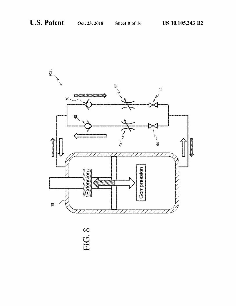
FIG . 8 discloses the most complex and powerful embodi - adjust the damping in the extension line but saves weight , ment of the fluid control circuit ( FCC ) . The fluid circuit size , and cost . But it lacks the ability to cutoff the compres splits into two branches . Each branch has a check valve 40 sion line and therefore does not have the standing stability oriented to permit fluid flow in either compression or feature of the earlier embodiments . extension alone , thereby separating the extension and com - 5 The embodiment of FIG . 14 is similar to the embodiment pression properties for the damper . In the compression line , of FIG . 8 , but lacks variable dampers 42 . The level of there is provided a variable restriction element 42 , where the resistance for compression can be adjusted by the prosthetist prosthetist could adjust the damping level to optimize the by changing springs or by pre - compressing the spring . prosthesis for the individual patient . In the extension line , Otherwise the function would be the same . there is also a variable restriction element 42 that could be 10 The embodiment of FIG . 15 is similar to the embodiment adjusted to tune the neutralization damping after toe - off to of FIG . 9 , but lacks variable dampers 42 . The level of address any issues with the speed of neutralization or with resistance for compression can be adjusted by the prosthetist noises that could arise from underdamped neutralization . by changing springs or by pre - compressing the spring . Both lines have independent cutoff valves 44 , allowing the FIG . 16 shows our simplest embodiment . There is a check extension damping to be raised to nearly infinite as appro - 15 valve 40 to permit compression , but not extension , and then priate during each step and then both cutoff valves to be when the foot is to be neutralized the cutoff valve is opened , closed for standing tasks , making a stable base of support for permitting extension by bypassing the check valve 40 . the user . Ideally the cutoff valve 44 would be mechanically opened
FIG . 9 discloses an embodiment that contains all of the and closed by loads applied during the gait cycle , resulting adjustability of the embodiment of FIG . 8 , but only a single 20 in a purely passive system with no batteries , microproces cutoff valve 44 is used on a common line to arrest both sors , or other electronic components , though this could be compression and extension of the damper simultaneously . actuated by a solenoid or other actuator and controlled by The advantage of this system over FIG . 8 is fewer parts ( one electronics fewer cutoff valve ) . The disadvantage of this system com While this invention has been described as having pre pared with the embodiment of FIG . 8 is that sensors would 25 ferred sequences , ranges , steps , order of steps , materials , need to be in place to insure that the cutoff valve would open structures , symbols , indicia , graphics , color scheme ( s ) , at the time of toe - off and close at exactly the time of foot flat shapes , configurations , features , components , or designs , it to prevent unexpected instability and potential falls . is understood that it is capable of further modifications , uses
FIG . 10 discloses an embodiment that is similar to the and / or adaptations of the invention following in general the embodiment of FIG . 8 , except it does not have a variable 30 principle of the invention , and including such departures restriction element 42 on the extension line . Therefore , there from the present disclosure as those come within the known is no way to tune the extension damping for neutralization or customary practice in the art to which the invention after toe - off . This embodiment is more efficient because of pertains , and as may be applied to the central features the reduced number of components ( saving weight , size and hereinbefore set forth , and fall within the scope of the cost ) but only if the fluid circuit can be optimized to allow 35 invention and of the limits of the claims appended hereto or the foot to return to neutral within 0 . 13 seconds without presented later . The invention , therefore , is not limited to the oscillating or making loud noises when it reaches the neutral preferred embodiment ( s ) shown / described herein . position . This system retains the ability to cutoff both compression and extension for standing tasks . REFERENCES
FIG . 11 discloses an embodiment similar to the embodi - 40 ments presented in both FIGS . 9 - 10 , however , it lacks the The following references , and any cited in the disclosure ability to adjust extension damping and has a single cutoff herein , are hereby incorporated herein in their entirety by valve 44 to arrest motion in both extension and compression reference . simultaneously . This is even more efficient , having removed 1 . Hansen , A . , Childress , D . , Miff , S . , Gard , S . , Mesplay , K . two components from the system and saving weight , size , 45 ( 2004 ) The Human Ankle During Walking : Implications and cost . The challenges with this embodiment have been for Design of Biomimetic Ankle Prostheses and Orthoses . discussed in paragraphs [ 0039 ] and [ 0040 ) . Journal of Biomechanics , Vol . 37 , No . 10 , 1467 - 1474 .
The embodiment of FIG . 12 is similar to the embodiment 2 . Williams R J , Hansen A H , Gard S A . ( 2009 ) Prosthetic of FIG . 8 , except that it does not have a cutoff valve 44 in Ankle - Foot Mechanism Capable of Automatic Adaptation the compression line . For this reason , the compression 50 to the Walking Surface . Journal of Biomechanical Engi damping will remain constant throughout the gait cycle and neering , Vol . , 131 , No . 3 , 035002 . compression motion will not be arrested during standing 3 . Hansen A , Brielmaier S , Medvec J , Pike A , Nickel E , tasks . Both lines have adjustable damping from the variable Merchak P , Weber M ( 2012 ) Prosthetic Foot with Adjust restriction elements and the extension line still has a cutoff a ble Stability and its Effects on Balance and Mobility . valve . This embodiment could be realized in a purely 55 38th Annual Meeting and Scientific Symposium of the passive system , where the biomechanics of walking ( e . g . American Academy of Orthotists and Prosthetists , March load on the prosthesis ) control the opening and closing of the 21 - 24 , Atlanta . Ga . cutoff valve . For example , a spring - loaded hinge or tele - 4 . Nickel E A , Hansen A H , Gard S A . ( 2012 ) Prosthetic scoping element within the prosthesis could close the cutoff Ankle - Foot System that Adapts to Sloped Surfaces . valve when load is applied to the prosthesis and open the 60 ASME Journal of Medical Devices , Vol . 6 , No . 1 , 011006 . cutoff valve when load is removed from the prosthesis . It would not be practical to rely on this type of physical input What is claimed is : to control the compression line for standing tasks , so none 1 . An ankle - foot prosthesis , comprising : of the previous embodiments would be practical for purely a ) a foot plate including a rear portion and a forward passive operation . 65 deflectable portion ;
The embodiment of FIG . 13 is similar to the embodiments b ) an ankle frame including anterior and posterior por of FIGS . 10 and 12 , however , it also lacks the ability to tions and an apex portion ;

US 10 , 105 , 243 B2 10
c ) said posterior portion of said ankle frame attached to j ) said fluid control circuit including a cutoff valve for said rear portion of said foot plate ; preventing compression and extension of said damper
d ) a yoke pivotally connected to said apex portion of said at prosthetic side foot between prosthetic side foot flat ankle frame and including a member for attaching to a and prosthetic side toe off during a walking mode of a prosthetic leg ; gait cycle ;
e ) a hydraulic damper having a first end pivotally con k ) said cutoff valve allowing compression and extension nected to said yoke and a second end pivotally con of said damper between prosthetic side toe off until nected to said posterior portion of said ankle frame ; prosthetic side foot flat during the walking mode of the f ) a spring disposed in parallel to said damper ; gait cycle ; and g ) a fluid control circuit for controlling extension and 10 1 ) said cutoff valve preventing compression and extension compression of said damper ; of said damper during a standing mode . h ) said anterior portion of said ankle frame including a 6 . The ankle - foot prosthesis of claim 5 , further compris curved surface inclined upwardly relative to said foot plate and forwardly toward said forward deflectable ing : portion of said foot plate ; 15 . a ) at least one check valve for said fluid control circuit for
i ) said curved surface forming a roll - over surface for allowing compression of said damper . limiting a dorsiflexion deflection of said forward 7 . The ankle - foot prosthesis of claim 5 , further compris deflectable portion of said foot plate by a direct engage - ing : ment therewith ; a ) at least one check valve for said fluid control circuit for
j ) said fluid control circuit including a check valve for 20 only allowing compression of said damper ; 8 . The ankle - foot prosthesis of claim 6 , further compris
k ) said fluid control circuit including a cutoff valve for ing : allowing extension of said damper ; a ) at least one variable fluid - flow resistor for said fluid
1 ) said cutoff valve allowing extension of said damper control circuit for adjusting hydraulic fluid resistance in during a gait cycle at least between prosthetic side toe 25 dorsiflexion , plantarflexion , or both . off and 0 to 0 . 13 seconds thereafter ; and 9 . An ankle - foot prosthesis , comprising :
m ) said cutoff valve allowing extension of said damper a ) a foot plate including a rear portion and a forward during the gait cycle at most between prosthetic side deflectable portion ; toe off and the next prosthetic side foot flat . b ) an ankle frame including anterior and posterior por 2 . The ankle - foot prosthesis of claim 1 , further compris - 30 tions and an apex portion ; ing : c ) said posterior portion of said ankle frame attached to a ) another check valve positioned in series with said cutoff said rear portion of said foot plate ; valve .
3 . The ankle - foot prosthesis of claim 2 , further compris d ) a yoke pivotally connected to said apex portion of said ing : ankle frame and including a member for attaching to a
a ) another cutoff valve for allowing compression of said prosthetic leg ; damper during a walking mode and preventing com e ) a hydraulic damper having a first end pivotally con pression of said damper during a standing mode . nected to said yoke and a second end pivotally con
4 . The ankle - foot prosthesis of claim 1 , further compris nected to said ankle frame ; 40 f ) a spring disposed in parallel to said damper ;
a ) at least one variable fluid - flow resistor for said fluid g ) a fluid control circuit for controlling extension and control circuit for adjusting hydraulic fluid resistance in compression of said damper ; dorsiflexion , plantarflexion , or both . h ) said anterior portion of said ankle frame including a
5 . An ankle - foot prosthesis , comprising : curved surface inclined upwardly relative to said foot a ) a foot plate including a rear portion and a forward 45 plate and forwardly toward said forward deflectable
deflectable portion ; portion of said foot plate ; and b ) an ankle frame including anterior and posterior por - i ) said curved surface forming a roll - over surface for
tions and an apex portion ; limiting a dorsiflexion deflection of said forward c ) said posterior portion of said ankle frame attached to deflectable portion of said foot plate by a direct engage
said rear portion of said foot plate ; ment therewith . d ) a yoke pivotally connected to said apex portion of said 10 . The ankle - foot prosthesis of claim 9 , wherein :
ankle frame and including a member for attaching to a a ) said fluid control circuit includes a check valve for only prosthetic leg ; allowing compression of said damper .
e ) a hydraulic damper having a first end pivotally con 11 . The ankle - foot prosthesis of claim 9 , wherein : nected to said yoke and a second end pivotally con - 55 a ) said fluid control circuit includes a cutoff valve for nected to said posterior portion of said ankle frame ; allowing extension of said damper .
f ) a spring disposed in parallel to said damper ; 12 . The ankle - foot prosthesis of claim 11 , wherein : g ) a fluid control circuit for controlling extension and a ) said cutoff valve allows extension of said damper
compression of said damper ; during a gait cycle at least between prosthetic side toe h ) said anterior portion of said ankle frame including a 60 off and 0 to 0 . 13 seconds thereafter .
curved surface inclined upwardly relative to said foot 13 . The ankle - foot prosthesis of claim 11 , wherein : plate and forwardly toward said forward deflectable a ) said cutoff valve allows extension of said damper portion of said foot plate ; during the gait cycle at most between prosthetic side
i ) said curved surface forming a roll - over surface for toe off and the next prosthetic side foot flat . limiting a dorsiflexion deflection of said forward 65 14 . The ankle - foot prosthesis of claim 9 , wherein : deflectable portion of said foot plate by a direct engage - a ) said fluid control circuit includes a cutoff valve for ment therewith ; preventing compression and extension of said damper
ing :
50

US 10 , 105 , 243 B2
at prosthetic side foot between prosthetic side foot flat and prosthetic side toe off during a walking mode of a gait cycle .
15 . The ankle - foot prosthesis of claim 14 , wherein : a ) said cutoff valve allows compression and extension of 5
said damper between prosthetic side toe off until pros thetic side foot flat during the walking mode of the gait cycle .
16 . The ankle - foot prosthesis of claim 15 , wherein : a ) said cutoff valve prevents compression and extension 10 of said damper during a standing mode .
17 . The ankle - foot prosthesis of claim 9 , wherein : a ) said fluid control circuit includes a check valve for only
allowing extension of said damper ; and b ) said cutoff valve opens or closes by a load applied to 15
the ankle - foot prosthesis during walking . 18 . The ankle - foot prosthesis of claim 17 , further com
prising : a ) an actuator operating with the load to open or close said
cutoff valve . 19 . The ankle - foot prosthesis of claim 18 , wherein : a ) said actuator comprises a spring - loaded hinge . 20 . The ankle - foot prosthesis of claim 18 , wherein : a ) said actuator comprises a telescoping element .
20
25