- 1 -ftp.uslinc.com/ftp/Products/IRC-21/Documents/IRC-21...Shielded, two conductor audio cable for...
6
181 Bonetti Drive San Luis Obispo, CA 93401 ph: 805-549-0161 fax: 805-549-0163 e-mail:[email protected] December, 2010
Transcript of - 1 -ftp.uslinc.com/ftp/Products/IRC-21/Documents/IRC-21...Shielded, two conductor audio cable for...

181
Bon
etti
Driv
eSa
n Lu
is O
bisp
o, C
A 93
401
ph: 8
05-5
49-0
161
fax:
805
-549
-016
3e-
mai
l:usl
@us
linc.
com
Dec
embe
r, 20
10
- 1 -
- 10
-

- 9 -
- 2 -
SAFE
TY IN
STRU
CTIO
NS....
........
........
........
........
........
........
........
........
........
...2UP
C-21
FEA
TURE
S.....
........
........
........
........
........
........
........
........
........
........
.. 3
UPC-
21 IN
STAL
LATI
ON....
........
........
........
........
........
........
........
........
........
.... 4
AUDI
O &
POW
ER C
ONNE
CTIO
NS....
........
........
........
........
........
........
........
... 5
PREL
IMIN
ARY
LEVE
L SE
TTIN
GS....
........
........
........
........
........
........
........
.... 6
MOUN
TING
THE
EMI
TTER
........
........
........
........
........
........
........
........
........
.... 6
INST
ALLA
TION
USI
NG T
WO
IRC-
21S.
........
........
........
........
........
........
........
. 8FA
CTS
ABOU
T IN
FRAR
ED T
RANS
MISS
ION
SYST
EMS.
........
........
........
... 9
Illus
trat
ions
:
UPC
FEAT
URES
........
........
........
........
........
........
........
........
........
... 3
UP
C-21
AUD
IO, P
OWER
CON
NECT
IONS
........
........
........
........
.. 5
SU
MMIN
G RE
SIST
OR N
ETW
ORK.
........
........
........
........
........
..... 5
DI
ODE
LIFE
EXP
ECTA
NCY
CHAR
T......
........
........
........
........
...... 7
FR
ONT
AND
REAR
MOU
NTED
VIE
WS.
........
........
........
........
..... 7
IN
STAL
LATI
ON U
SING
2 IR
C-21
S.....
........
........
........
........
........
. 8
TAB
LE O
F C
ON
TEN
TS
1) R
ead
thes
e in
stru
ctio
ns.
2) K
eep
thes
e in
stru
ctio
ns.
3) H
eed
all w
arni
ngs.
4) F
ollo
w a
ll in
stru
ctio
ns.
5) D
o no
t use
this
app
arat
us n
ear w
ater
.6)
Cle
an o
nly
with
dry
clo
th.
7) D
o no
t blo
ck a
ny v
entil
atio
n op
enin
gs. I
nsta
ll in
acc
orda
nce
with
the
man
ufac
ture
r’s
inst
ruct
ions
.8)
Do
not i
nsta
ll ne
ar a
ny h
eat s
ourc
es s
uch
as ra
diat
ors,
hea
t reg
iste
rs, s
tove
s, o
r oth
er
appa
ratu
s (in
clud
ing
ampl
ifier
s) th
at p
rodu
ce h
eat.
9) D
o no
t def
eat t
he s
afet
y pu
rpos
e of
the
pola
rized
or g
roun
ding
-type
plu
g. A
pol
ariz
ed
plug
has
two
blad
es w
ith o
ne w
ider
than
the
othe
r. A
grou
ndin
g ty
pe p
lug
has
two
blad
es
and
a th
ird g
roun
ding
pro
ng. T
he w
ide
blad
e or
the
third
pro
ng a
re p
rovi
ded
for y
our
safe
ty. I
f the
pro
vide
d pl
ug d
oes
not f
it in
to y
our o
utle
t, co
nsul
t an
elec
trici
an fo
r rep
lace
-m
ent o
f the
obs
olet
e ou
tlet.
10) P
rote
ct th
e po
wer
cor
d fro
m b
eing
wal
ked
on o
r pin
ched
par
ticul
arly
at p
lugs
, con
ve-
nien
ce re
cept
acle
s, a
nd th
e po
int w
here
they
exi
t fro
m th
e ap
para
tus.
11) O
nly
use
atta
chm
ents
/acc
esso
ries
spec
ified
by
the
man
ufac
ture
r.
12) U
se o
nly
with
the
cart,
sta
nd, t
ripod
, bra
cket
, or t
able
spe
cifie
d by
the
m
anuf
actu
rer,
or s
old
with
the
appa
ratu
s. W
hen
a ca
rt is
use
d, u
se c
autio
n
w
hen
mov
ing
the
cart/
appa
ratu
s co
mbi
natio
n to
avo
id in
jury
from
tip-
over
.13
) Unp
lug
this
app
arat
us d
urin
g lig
htni
ng s
torm
s or
whe
n un
used
for l
ong
perio
ds o
f tim
e.14
) Ref
er a
ll se
rvic
ing
to q
ualif
ied
serv
ice
pers
onne
l. S
ervi
cing
is re
quire
d w
hen
the
ap-
para
tus
has
been
dam
aged
in a
ny w
ay, s
uch
as p
ower
-sup
ply
cord
or p
lug
is d
amag
ed,
liqui
d ha
s be
en s
pille
d or
obj
ects
hav
e fa
llen
into
the
appa
ratu
s, th
e ap
para
tus
has
been
ex
pose
d to
rain
or m
oist
ure,
doe
s no
t ope
rate
nor
mal
ly, o
r has
bee
n dr
oppe
d.
WA
RN
ING
To re
duce
the
risk
of fi
re o
r ele
ctric
sho
ck, d
o no
t exp
ose
this
app
lianc
e to
rain
or m
oist
ure.
IMPO
RTA
NT
SAFE
TY IN
STR
UC
TIO
NS
- 3 -
- 8 -
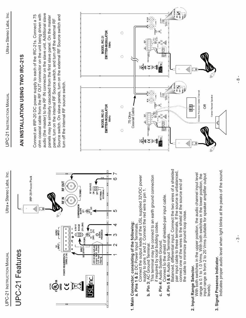
1. M
ain
Con
nect
or; c
onsi
stin
g of
the
follo
win
g:
a. P
ins
1 &
2: D
C P
ower
Inpu
t Ter
min
als.
Con
nect
the
outp
ut le
ads
of th
e U
SL
supp
lied
32V
DC
pow
er
su
pply
to p
ins
1 an
d 2.
Con
nect
the
red
wire
to p
in 1
.
b. P
in 3
: AC
Gro
und
Term
inal
.
Th
is te
rmin
al m
ay b
e co
nnec
t to
an e
arth
gro
und
conn
ectio
n
if
requ
ired
by lo
cal b
uild
ing
code
s.
c. P
in 4
: Aud
io S
yste
m G
roun
d.
C
onne
ct to
the
shie
ld o
f shi
elde
d-pa
ir in
put c
able
.
d. P
in 5
& 6
: Aud
io In
put T
erm
inal
s.
B
alan
ced,
diff
eren
tial i
nput
. Con
nect
the
two
wire
s of
a s
hiel
ded
pa
ir in
put c
able
to th
ese
term
inal
s. If
the
sour
ce is
unb
alan
ced,
conn
ect o
ne o
f the
wire
s to
the
shie
ld a
t the
sou
rce
end
of
th
e ca
ble
to m
inim
ize
grou
nd lo
op n
oise
.
2. In
put R
ange
Sel
ecto
r.
With
bot
h sw
itche
s in
the
uppe
r pos
ition
, the
aud
io c
hann
el in
put l
evel
ra
nge
is 0
.1 to
1.0
Vrm
s. W
ith b
oth
switc
hes
in th
e lo
wer
pos
ition
, the
in
put r
ange
is fr
om 2
to 2
0 Vr
ms
(sui
tabl
e fo
r spe
aker
am
plifi
er o
utpu
t
le
vels
).
3. S
igna
l Pre
senc
e In
dica
tor.
In
dica
tes
prop
er a
udio
leve
l whe
n lig
ht b
links
at t
he p
eaks
of t
he s
ound
.
Con
nect
an
IRP
-20
DC
pow
er s
uppl
y to
eac
h of
the
IRC
-21s
. Con
nect
a 7
5 oh
m c
oaxi
al c
able
from
the
RF
OU
T co
nnec
tor o
n th
e un
it be
ing
driv
en w
ith
audi
o (th
e m
aste
r) to
the
RF
IN c
onne
ctor
on
the
slav
e un
it. A
dditi
onal
sla
ve
pane
ls m
ay b
e si
mila
rly c
asca
ded
from
the
first
sla
ve p
anel
. On
the
mas
ter
pane
l, tu
rn o
n th
e in
tern
al R
F S
ourc
e sw
itch,
and
turn
off
the
exte
rnal
RF
Sou
rce
switc
h. O
n sl
ave
pane
ls, t
urn
on th
e ex
tern
al R
F S
ourc
e sw
itch
and
turn
off
the
inte
rnal
RF
sour
ce s
witc
h.
AN
INST
ALL
ATIO
N U
SIN
G T
WO
IRC
-21S

- 7 -
- 4 -
4. A
udio
Inpu
t lev
el A
djus
tmen
t.
Adj
ust i
nput
leve
l so
that
onl
y th
e pe
aks
of th
e au
dio
sign
al li
ght t
he L
ED
“Sig
nal P
rese
nce”
indi
cato
r. If
the
LED
is o
n co
nsta
ntly,
the
audi
o le
vel
is to
o hi
gh a
nd th
e ch
anne
l is
clip
ping
.
5. C
ompr
essi
on S
lope
Adj
ustm
ent.
A
djus
ts c
ompr
essi
on fr
om 1
:1 to
3:1
with
2:1
at t
he a
ppro
xim
ate
cent
er
of th
e ra
nge.
Impr
oves
inte
lligi
bilit
y of
low
leve
l dia
log.
6. R
F So
urce
Sw
itch.
S
elec
ts s
ourc
e of
IR R
F m
odul
atio
n to
be
radi
ated
by
this
em
itter
pan
el.
The
left
switc
h fe
eds
the
loca
l aud
io m
odul
ated
RF
to th
e em
itter
pan
el.
The
right
sw
itch
conn
ects
the
emitt
er p
anel
to a
n ex
tern
al s
ourc
e, s
uch
as
ano
ther
IRC
-21
loca
ted
in a
noth
er c
orne
r of t
he a
udito
rium
.
7.
RF
Inpu
t and
Out
put B
NC
Con
nect
ors.
Th
e R
F In
put c
onne
ctor
acc
epts
RF
from
ano
ther
IRC
-21
for r
adia
tion
fro
m th
is e
mitt
er p
anel
. The
RF
outp
ut c
onne
ctor
feed
s th
e m
odul
ated
R
F ou
tput
from
this
mod
ulat
or to
ano
ther
pan
el.
One
sys
tem
man
ual
One
IRC
-21
Em
itter
Pan
el
One
IRP
-20
32V
DC
Pow
er S
uppl
y
One
Mou
ntin
g B
rack
et c
ompo
sed
of 1
ea.
IRB
S-2
0 &
IRB
E-2
0
Two
10-3
2 x
5/8
mac
hine
scr
ews
for a
ttach
ing
the
emitt
er p
anel
to
the
mou
ntin
g br
acke
t.
Unp
ack
the
cart
on a
nd v
erify
that
all
mat
eria
ls a
re p
rese
nt.
Ther
e sh
ould
be:
UP
C-2
1 In
stal
latio
n
You
will
nee
d to
sup
ply
the
follo
win
g m
ater
ials
:A
smal
l jew
eler
’s ty
pe fl
at b
lade
scr
ewdr
iver
or t
rim p
ot a
lignm
ent
tool
for a
djus
ting
the
inpu
t aud
io le
vels
.
A m
ediu
m fl
at b
lade
scr
ewdr
iver
for a
ttach
ing
the
mou
ntin
g br
acke
t.
Shi
elde
d, tw
o co
nduc
tor a
udio
cab
le fo
r con
nect
ion
of th
e IR
C-2
1 to
the
prog
ram
sou
rce.
If th
e co
rd o
n th
e IR
P-2
0 po
wer
sup
ply
is n
ot lo
ng e
noug
h, y
ou w
ill
need
add
ition
al #
18 A
WG
or l
arge
r tw
o or
thre
e co
nduc
tor c
able
to
exte
nd th
e D
C o
utpu
t cab
le. I
f thr
ee c
ondu
ctor
cab
le is
use
d, th
e th
ird c
ondu
ctor
can
mak
e th
e sa
fety
gro
und
conn
ectio
n
Tool
s an
d ha
rdw
are
to a
ttach
the
mou
ntin
g br
acke
t to
the
wal
l
One
IRH
-501
or I
RH
-701
rece
iver
.

- 5 -
- 6 -
Con
nect
the
cent
er c
hann
el s
peak
er te
rmin
als
to th
e +
and
- (gr
ound
) aud
io
inpu
t ter
min
als
on th
e IR
C-2
1 as
in F
ig C
. If t
he c
ente
r cha
nnel
is b
i-am
ped,
yo
u m
ust c
onst
ruct
a r
esis
tor
netw
ork,
as
in F
ig. D
, tha
t sum
s th
e hi
gh a
nd
low
freq
uenc
y si
gnal
s, th
en fe
ed th
e ou
tput
of t
he n
etw
ork
to th
e IR
C-2
1 au
dio
inpu
t. Yo
u al
so m
ay c
onne
ct th
e IR
C-2
1 in
put
to th
e ou
tput
of a
mon
itor o
r a
proc
esso
r.
CO
NN
ECT
THE
AU
DIO
INPU
T LI
NE
CO
NN
ECT
THE
IRP-
20 D
C P
OW
ER P
AC
K
Con
nect
the
prov
ided
IRP
-20
DC
pow
er s
uppl
y to
the
IRC
-21
pow
er in
put t
erm
inal
s (1
an
d 2)
. If t
he D
C s
uppl
y ca
ble
need
s to
be
exte
nded
, ref
er
to ta
ble
1 fo
r sug
gest
ed w
ire
size
s. M
ake
sure
ther
e ar
e no
loos
e w
ire s
trand
s at
the
term
inal
s to
avo
id p
oten
tial
shor
t circ
uits
.
D
O N
OT
SHO
RT
THE
POW
ER S
UPP
LY!
Con
nect
the
pow
er s
uppl
y to
an
AC
out
let (
100
- 240
VAC
, 50
/60H
z) u
sing
the
supp
lied
or a
sta
ndar
d IE
C p
ower
cor
d.
P
REL
IMIN
ARY
LEV
EL S
ETTI
NG
Run
pro
gram
mat
eria
l with
HI a
udio
. Set
the
com
pres
sion
slo
pe to
2:1
.A
djus
t the
app
ropr
iate
DIP
sw
itche
s an
d in
put l
evel
con
trols
to c
ause
the
audi
ole
vel L
ED
s to
flas
h dr
uing
nor
mal
pro
gram
min
g, b
ut n
ot to
sta
y lit
con
tinuo
usly.
Try
liste
ning
on
IR h
eadp
hone
s. If
nec
essa
ry, a
djus
t com
pres
sion
to b
ring
up
low
leve
ls o
r red
uce
nois
e.
N
ote:
The
IRC
-20
has
an a
utom
atic
shu
toff
circ
uit.
The
unit
will
sh
ut it
self
off a
fter a
thirt
y-m
inut
e ab
senc
e of
aud
io in
put.
W
hen
the
audi
o re
sum
es, t
he p
anel
will
sw
itch
on im
med
iate
ly.
M
ount
ing
the
Emitt
er/M
odul
ator
at t
he fr
ont o
f the
aud
itoriu
m (S
ee F
igur
es F
and
G) A
ttach
the
supp
lied
mou
ntin
g br
acke
t to
the
wal
l sur
face
an
d us
e th
e su
pplie
d sc
rew
s to
atta
ch th
e br
acke
t to
the
emitt
er. A
llow
free
airf
low
ar
ound
the
emitt
er a
nd b
e su
re to
hav
e at
leas
t eig
ht in
ches
cle
aran
ce fr
om a
ll su
rface
s, p
refe
rabl
y m
ore
if at
all
poss
ible
. The
rear
pan
el is
use
d as
a h
eat s
ink
and
the
heat
mus
t be
allo
wed
to d
issi
pate
. The
uni
t sho
uld
be m
ount
ed to
the
side
of
the
scre
en/s
tage
are
a, 1
2 to
15
feet
abo
ve th
e au
dien
ce’s
hea
ds a
nd p
oint
ed
dow
nwar
d an
d in
to th
e se
atin
g ar
ea.
M
ount
ing
the
Emitt
er/M
odul
ator
at t
he re
ar o
f the
aud
itoriu
m
Atta
ch th
e su
pplie
d m
ount
ing
brac
ket t
o th
e w
all s
urfa
ce a
nd u
se th
e su
pplie
d sc
rew
s to
atta
ch th
e br
acke
t to
the
emitt
er. A
llow
free
airf
low
aro
und
the
emitt
er
and
be s
ure
to h
ave
at le
ast f
our i
nche
s cl
eara
nce
from
all
surfa
ces,
pre
ferr
ably
m
ore.
The
rear
pan
el is
use
d as
a h
eat s
ink
and
mus
t be
allo
wed
to d
issi
pate
hea
t. Th
e em
itter
will
cov
er u
p to
5,5
00 s
quar
e fe
et (6
0 x
84 fe
et).
The
emitt
er is
typi
-ca
lly m
ount
ed n
ear t
he p
roje
ctor
win
dow
. The
pan
el s
houl
d be
“aim
ed” t
owar
ds th
e sc
reen
. Thi
s ty
pica
lly re
sults
in th
e pa
nel b
eing
ver
tical
and
par
alle
l to
the
rear
wal
l of
the
audi
toriu
m. A
imin
g th
e pa
nel t
owar
ds th
e sc
reen
pro
vide
s ad
ditio
nal a
udito
-riu
m c
over
age
from
scr
een
refle
ctio
n.
CA
UTI
ON
: The
rear
pan
el m
ay g
et q
uite
war
m to
the
touc
h. T
his
is n
orm
al.