- 1 - Embedded Systems – Language SystemC: Motivation Many standards (e.g. the GSM and...
34
- 1 - Embedded Systems – Language SystemC: Motivation • Many standards (e.g. the GSM and MPEG- standards) are published as C programs Standards have to be translated if special hardware description languages have to be used (synthesizable) • The functionality of many systems is provided by a mix of hardware and software components Simulations require an interface between hardware and software simulators unless the same language is used for the description of hardware and software Attempts to describe software and hardware in the same language. (Easier said than
-
Upload
neal-douglas -
Category
Documents
-
view
225 -
download
0
Transcript of - 1 - Embedded Systems – Language SystemC: Motivation Many standards (e.g. the GSM and...
- 1 -Embedded Systems – Language
SystemC: Motivation
• Many standards (e.g. the GSM and MPEG-standards) are published as C programs
Standards have to be translated if special hardware description languages have to be used (synthesizable)
• The functionality of many systems is provided by a mix of hardware and software components
Simulations require an interface between hardware and software simulators unless the same language is used for the description of hardware and software
Attempts to describe software and hardware in the same language. (Easier said than implemented). Various C dialects used for hardware description.

- 2 -Embedded Systems – Language
SystemC: Motivation
• Represent hardware structure in software language needed.
• Problems:
– Model concurrency (hardware) in software
– A representation for simulation in time
– Support multiple-valued logic and resolution
– Deterministic behavior.
• Represent hardware structure in software language needed.
• Problems:
– Model concurrency (hardware) in software
– A representation for simulation in time
– Support multiple-valued logic and resolution
– Deterministic behavior.
- 3 -Embedded Systems – Language
SystemC: Required features
Requirements and solutions for modeling HW in a SW language:
• C++ class library including required functions.• Concurrency: via processes, controlled by sensivity lists
and calls to wait primitives.• Time: Floating point numbers in SystemC 1.0 and Integer
values in SystemC 2.0; includes units such as ps, ns, µs,..• Support of bit-data types: bit-vectors of different lengths;
multiple-valued logic (2- and 4-valued logic; resolution*)• Communication: plug-and-play channel model, allowing
easy replacement of intellectual property (IP).Deterministic behavior not guaranteed.
- 4 -Embedded Systems – Language
SystemC
• Potenital replacing VHDL-based design flow.• Hardware synthesize availability (coming?????) • EDA !!!
• Potenital replacing VHDL-based design flow.• Hardware synthesize availability (coming?????) • EDA !!!
- 5 -Embedded Systems – Language
Verilog
HW description language competing with VHDLStandardized:• IEEE 1364-1995 (Verilog version 1.0)• IEEE 1364-2001 (Verilog version 2.0)Features similar to VHDL:• Designs described as connected entities (modules).• Bit-vectors and time units are supportedFeatures that are different:• Built-in support for 4-value logic and for logic with 8
strength levels encoded in two bytes per signal.• More features for transistor-level descriptions• Less flexible than VHDL.• More popular in the US (VHDL common in Europe)
- 6 -Embedded Systems – Language
SystemVerilog
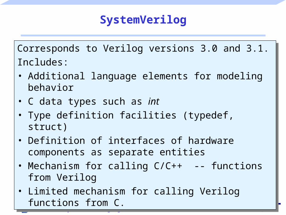
Corresponds to Verilog versions 3.0 and 3.1.
Includes:• Additional language elements for modeling behavior• C data types such as int• Type definition facilities (typedef, struct)• Definition of interfaces of hardware components as
separate entities• Mechanism for calling C/C++ -- functions from Verilog• Limited mechanism for calling Verilog functions from C.

- 7 -Embedded Systems – Language
SystemVerilog
• Enhanced features for describing the testbench• Classes can be used in testbenches.• Dynamic process creation.• Standardized inter-process communication and
synchronization.• Automatic memory allocation and de-allocation.• Language features providing interface for formal
verification. Significant hype about the potential of SystemVerilog
Emperors new cloths?
- 8 -Embedded Systems – Language
SpecC [Gajski, Dömer et. al. 2000]
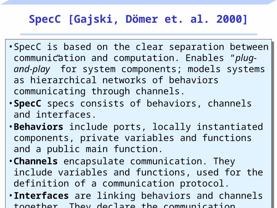
• SpecC is based on the clear separation between communication and computation. Enables “plug-and-play” for system components; models systems as hierarchical networks of behaviors communicating through channels.
• SpecC specs consists of behaviors, channels and interfaces.• Behaviors include ports, locally instantiated components,
private variables and functions and a public main function.• Channels encapsulate communication. They include
variables and functions, used for the definition of a communication protocol.
• Interfaces are linking behaviors and channels together. They declare the communication protocols which are defined in a channel.
- 9 -Embedded Systems – Language
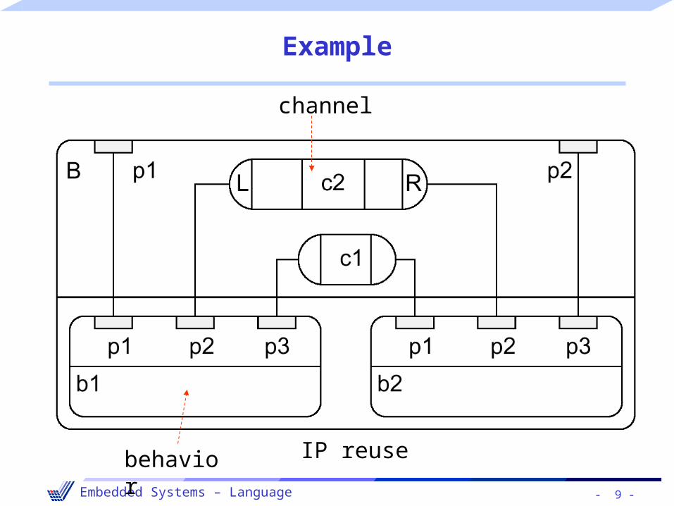
Example
channel
behavior IP reuse
- 10 -Embedded Systems – Language
Other languages (1)
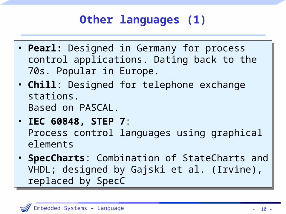
• Pearl: Designed in Germany for process control applications. Dating back to the 70s. Popular in Europe.
• Chill: Designed for telephone exchange stations.Based on PASCAL.
• IEC 60848, STEP 7:Process control languages using graphical elements
• SpecCharts: Combination of StateCharts and VHDL; designed by Gajski et al. (Irvine), replaced by SpecC

- 11 -Embedded Systems – Language
Other languages (2)
• Estelle: Designed to describe communication protocols; scope similar to SDL; unification of both failed.
• LOTOS, Z: Algebraic specification languages• Silage: functional language for digital signal processing.• Rosetta: Efforts on new system design language• Esterel: reactive language; synchronous;
all reactions are assumed to be in 0 time;communication based on ("instantenous") broadcast;//www.esterel-technologies.com
- 12 -Embedded Systems – Language
MATLAB/Simulink
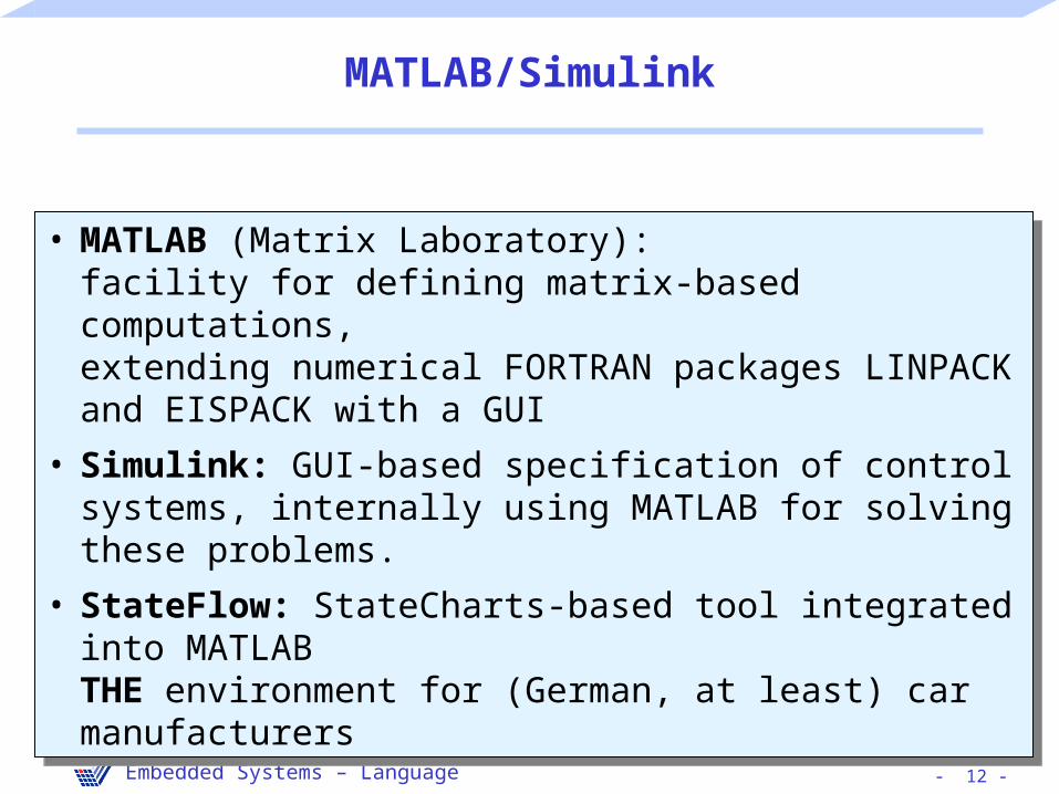
• MATLAB (Matrix Laboratory):facility for defining matrix-based computations,extending numerical FORTRAN packages LINPACK and EISPACK with a GUI
• Simulink: GUI-based specification of control systems, internally using MATLAB for solving these problems.
• StateFlow: StateCharts-based tool integrated into MATLABTHE environment for (German, at least) car manufacturers
- 13 -Embedded Systems – Language
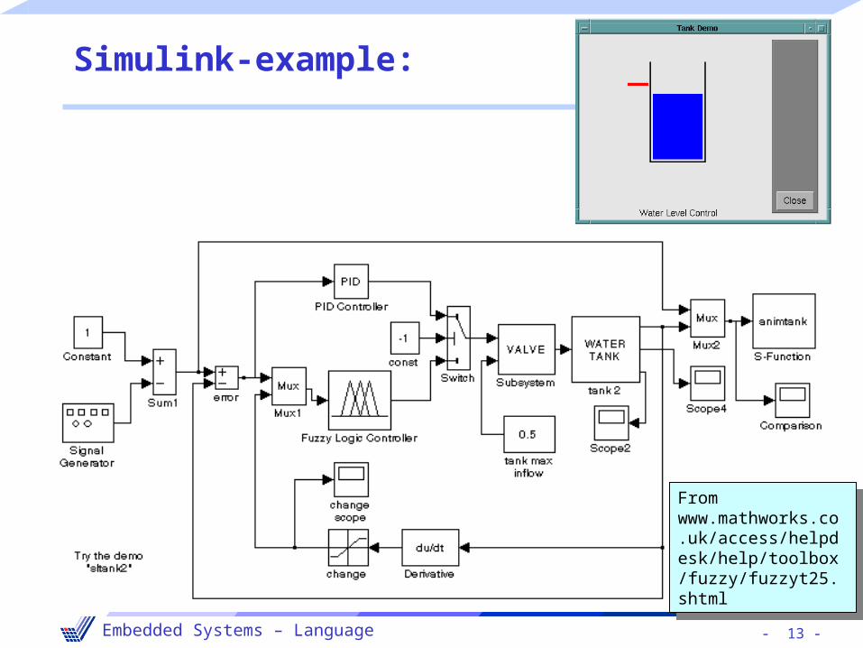
Simulink-example:
From www.mathworks.co.uk/access/helpdesk/help/toolbox/fuzzy/fuzzyt25.shtml
From www.mathworks.co.uk/access/helpdesk/help/toolbox/fuzzy/fuzzyt25.shtml
- 14 -Embedded Systems – Language
Levels of hardware modeling in design
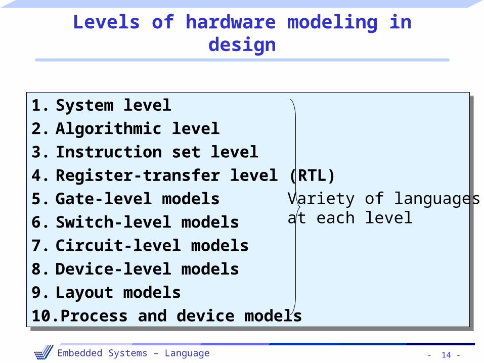
1. System level
2. Algorithmic level
3. Instruction set level
4. Register-transfer level (RTL)
5. Gate-level models
6. Switch-level models
7. Circuit-level models
8. Device-level models
9. Layout models
10.Process and device models
1. System level
2. Algorithmic level
3. Instruction set level
4. Register-transfer level (RTL)
5. Gate-level models
6. Switch-level models
7. Circuit-level models
8. Device-level models
9. Layout models
10.Process and device models
Variety of languagesat each level

- 15 -Embedded Systems – Language
System level
• The term system level is not clearly defined.• It is used here to denote the entire embedded system and
the system into which information processing is embedded, and possibly also the environment.
• Such models may include mechanical as well as information processing aspects, and may be difficult to find appropriate simulators. Solutions include VHDL-AMS (analog extension), SystemC or MATLAB. MATLAB and VHDL-AMS support modeling partial differential equations.
• Challenge to model information processing parts of the system in such a way that the simulation model can also be used for the synthesis of the embedded system.

- 16 -Embedded Systems – Language
Algorithmic level
• Simulating the algorithms that we intend to use within the embedded system (to evaluate the algorithm).
• No reference is made to processors or instruction sets.• Data types may still allow a higher precision than the final
implementation (complicated to implement).• If data types have been selected such that every bit
corresponds to exactly one bit in the final implementation, the model is said to be bit-true. Translating non-bit-true into bit-true models should be done with tool support.
• May consist of single process or of sets of cooperating processes.
- 17 -Embedded Systems – Language
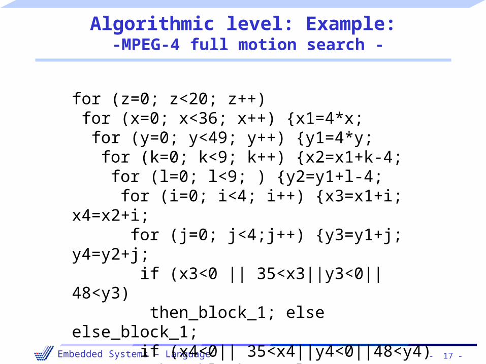
Algorithmic level: Example: -MPEG-4 full motion search -
for (z=0; z<20; z++) for (x=0; x<36; x++) {x1=4*x; for (y=0; y<49; y++) {y1=4*y; for (k=0; k<9; k++) {x2=x1+k-4; for (l=0; l<9; ) {y2=y1+l-4; for (i=0; i<4; i++) {x3=x1+i; x4=x2+i; for (j=0; j<4;j++) {y3=y1+j; y4=y2+j; if (x3<0 || 35<x3||y3<0||48<y3) then_block_1; else else_block_1; if (x4<0|| 35<x4||y4<0||48<y4) then_block_2; else else_block_2;}}}}}}
- 18 -Embedded Systems – Language
Instruction level
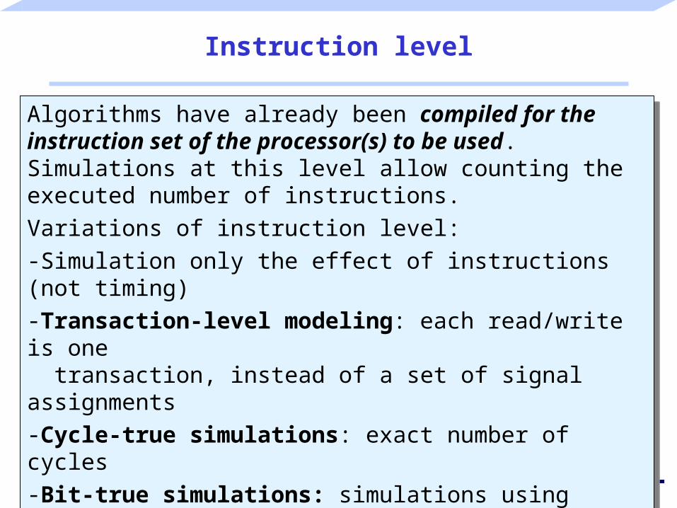
Algorithms have already been compiled for the instruction set of the processor(s) to be used. Simulations at this level allow counting the executed number of instructions.
Variations of instruction level: -Simulation only the effect of instructions (not timing)-Transaction-level modeling: each read/write is one transaction, instead of a set of signal assignments-Cycle-true simulations: exact number of cycles-Bit-true simulations: simulations using exactly the correct number of bits
- 19 -Embedded Systems – Language
Instruction level: example
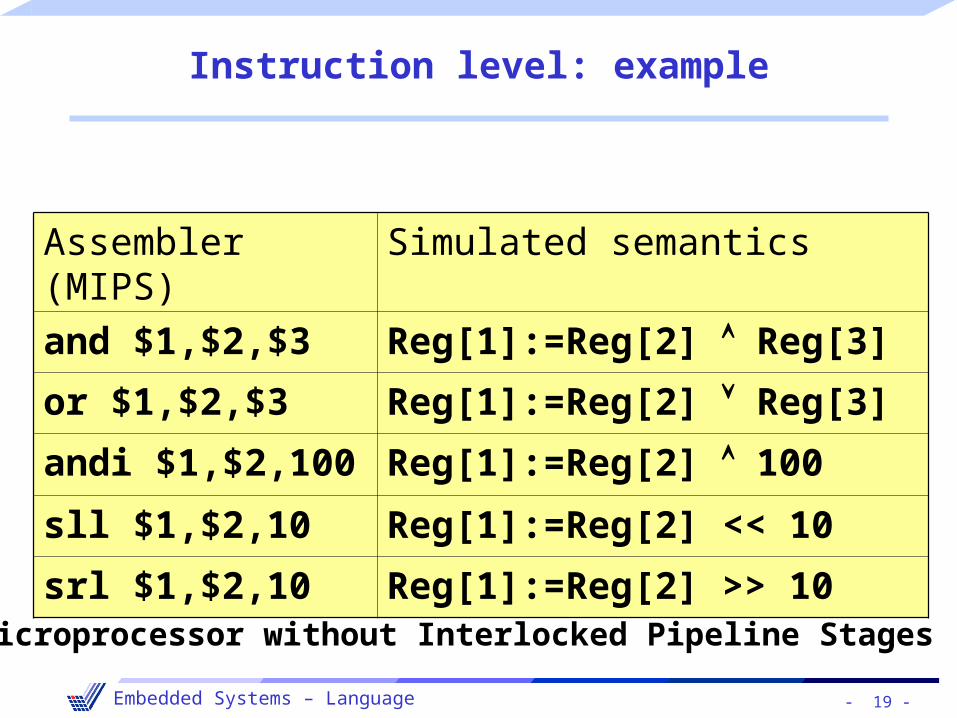
Assembler (MIPS) Simulated semantics
and $1,$2,$3 Reg[1]:=Reg[2] Reg[3]
or $1,$2,$3 Reg[1]:=Reg[2] Reg[3]
andi $1,$2,100 Reg[1]:=Reg[2] 100
sll $1,$2,10 Reg[1]:=Reg[2] << 10
srl $1,$2,10 Reg[1]:=Reg[2] >> 10
Microprocessor without Interlocked Pipeline Stages

- 20 -Embedded Systems – Language
Register transfer level (RTL)
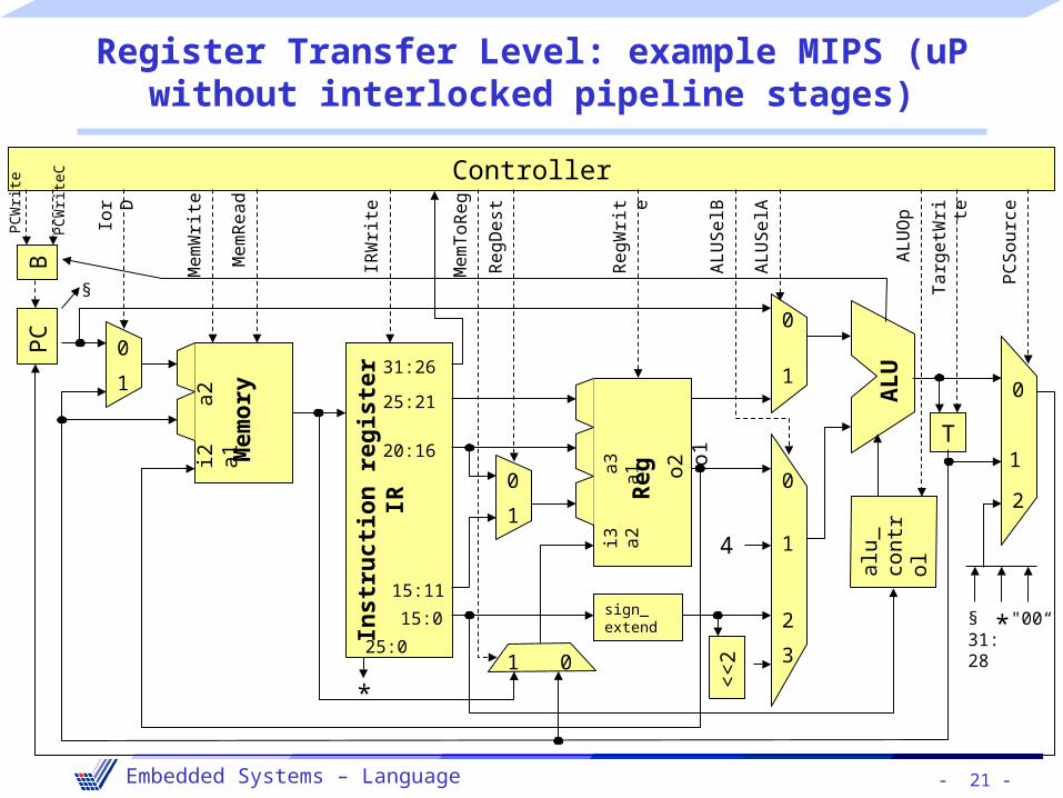
At this level, we model all the components at the register-transfer level, including- arithmetic/logic units (ALUs),- registers,- memories,- muxes and- decoders.
Models at this level are always cycle-true.
Automatic synthesis from such models is not a major challenge.
At this level, we model all the components at the register-transfer level, including- arithmetic/logic units (ALUs),- registers,- memories,- muxes and- decoders.
Models at this level are always cycle-true.
Automatic synthesis from such models is not a major challenge.
- 21 -Embedded Systems – Language
Register Transfer Level: example MIPS (uP without interlocked pipeline stages)
Controller
BP
C
Inst
ruct
ion
reg
iste
r IR
Mem
ory
Spe
iche
r
alu_
co
ntro
l
T
sign_extend
<<
2
4
*
AL
U
Reg
0
0
0
0
0
01
1
1
1
1
1
2
2
3
§
31:26
25:21
20:16
25:0
15:0
15:11
i2
a2
a1
i3
a
3
a
2
a
1
o2
o1
PC
So
urc
e
Ta
rge
tWrit
e
AL
UO
p
AL
US
elA
AL
US
elB
Re
gW
rite
Re
gD
est
Me
mT
oR
eg
IRW
rite
Me
mR
ea
d
Me
mW
rite
PC
Writ
e
PC
Wr it
eC
IorD
*§ 31: 28
"00“
- 22 -Embedded Systems – Language
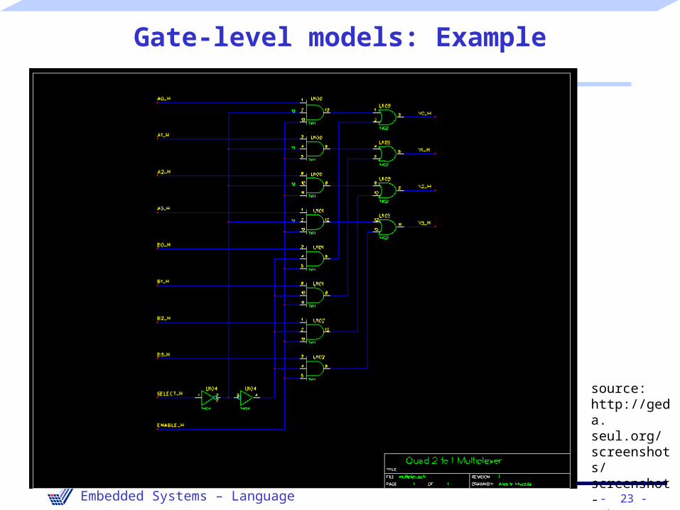
Gate-level models
• Models contain gates as the basic components.• Provide accurate information about signal transition
probabilities and can therefore also be used for power estimations.
• Delay calculations can be more precise than for the RTL. Typically no information about the length of wires (still estimates).
• Term sometimes also employed to denote Boolean functions (No physical gates; only considering the behavior of the gates).Such models should be called “Boolean function models”.
- 23 -Embedded Systems – Language
Gate-level models: Example
source: http://geda.seul.org/screenshots/screenshot-schem2.png

- 24 -Embedded Systems – Language
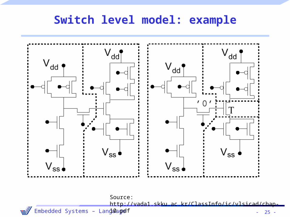
Switch-level models
• Switch level models use switches (transistors) as their basic components.
• Switch level models use digital values models (0,1,Z).• In contrast to gate-level models, switch level models are
capable of reflecting bidirectional transfer of information.
• Switch level models use switches (transistors) as their basic components.
• Switch level models use digital values models (0,1,Z).• In contrast to gate-level models, switch level models are
capable of reflecting bidirectional transfer of information.
- 25 -Embedded Systems – Language
Switch level model: example
Source: http://vada1.skku.ac.kr/ClassInfo/ic/vlsicad/chap-10.pdf
- 26 -Embedded Systems – Language
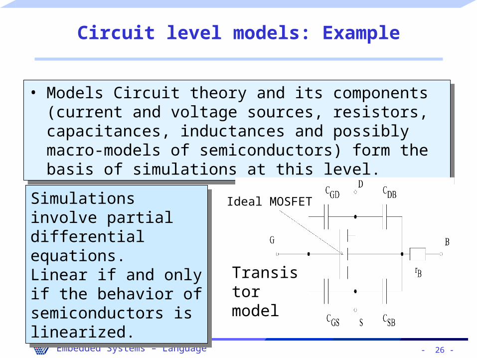
Circuit level models: Example
• Models Circuit theory and its components (current and voltage sources, resistors, capacitances, inductances and possibly macro-models of semiconductors) form the basis of simulations at this level.
• Models Circuit theory and its components (current and voltage sources, resistors, capacitances, inductances and possibly macro-models of semiconductors) form the basis of simulations at this level.
Simulations involve partial differential equations. Linear if and only if the behavior of semiconductors is linearized.
Simulations involve partial differential equations. Linear if and only if the behavior of semiconductors is linearized.
Ideal MOSFET
Transistor model
- 27 -Embedded Systems – Language
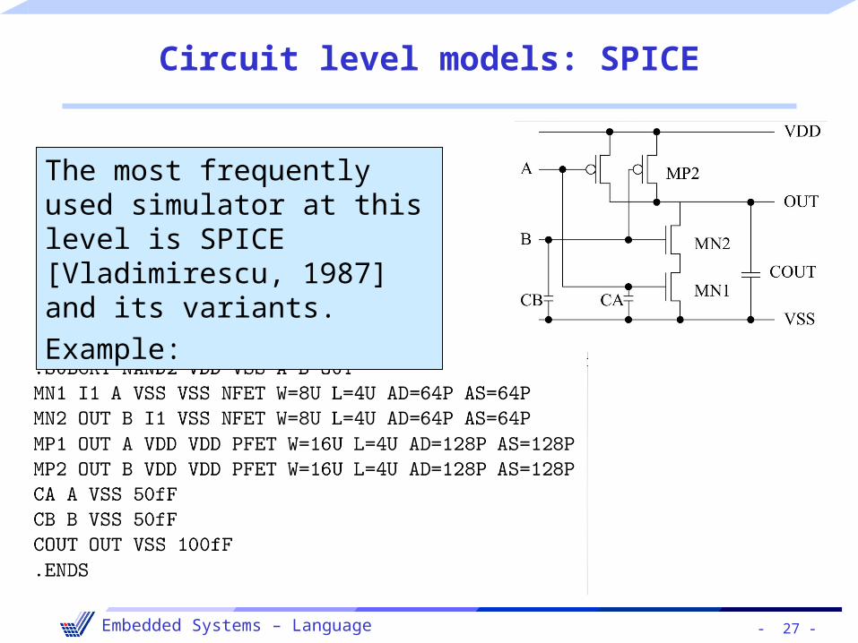
Circuit level models: SPICE
The most frequently used simulator at this level is SPICE [Vladimirescu, 1987] and its variants.
Example:

- 28 -Embedded Systems – Language
Circuit level models:sample simulation results
- 29 -Embedded Systems – Language
Device level
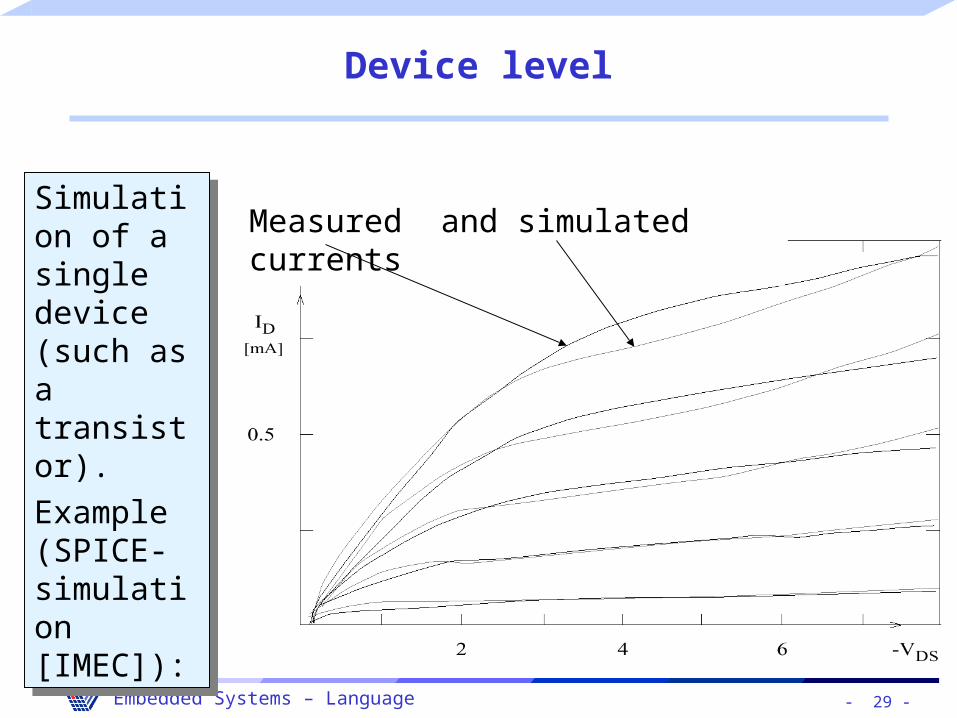
Simulation of a single device(such as a transistor).
Example (SPICE-simulation [IMEC]):
Simulation of a single device(such as a transistor).
Example (SPICE-simulation [IMEC]):
Measured and simulated currents
- 30 -Embedded Systems – Language
Layout models
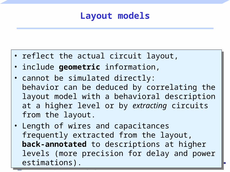
• reflect the actual circuit layout,• include geometric information,• cannot be simulated directly:
behavior can be deduced by correlating the layout model with a behavioral description at a higher level or by extracting circuits from the layout.
• Length of wires and capacitances frequently extracted from the layout, back-annotated to descriptions at higher levels (more precision for delay and power estimations).

- 31 -Embedded Systems – Language
Layout models: Example
din
powlo
powhi
dout
© Mosis (http://www. mosis.org/Technical/Designsupport/polyflowC.html);Tool: Cadence
- 32 -Embedded Systems – Language
Process models
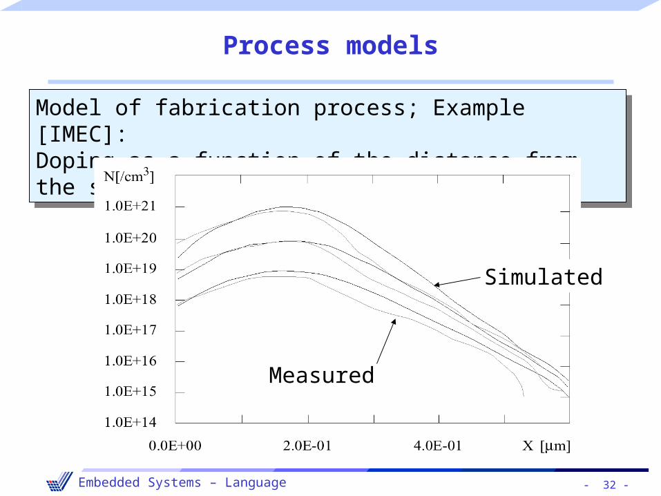
Model of fabrication process; Example [IMEC]:Doping as a function of the distance from the surface
Model of fabrication process; Example [IMEC]:Doping as a function of the distance from the surface
Simulated
Measured
- 33 -Embedded Systems – Language
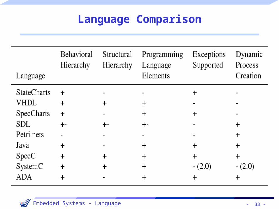
Language Comparison
- 34 -Embedded Systems – Language
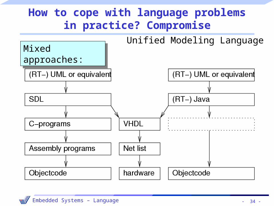
How to cope with language problemsin practice? Compromise
Mixed approaches:Mixed approaches:Unified Modeling Language


![EfficientBit AllocationAlgorithmFor MPEG-4 Audio · as MPEG-1/2/4 audio coding standards and Dolby AC-3 [1]. The MPEG-4 Advanced Audio Coding (AAC) is one ofthe mostrecent-generation](https://static.fdocuments.net/doc/165x107/5b3b16727f8b9a26728c2604/efficientbit-allocationalgorithmfor-mpeg-4-audio-as-mpeg-124-audio-coding.jpg)